EP1995371A1 - Appareil ménager électrique - Google Patents
Appareil ménager électrique Download PDFInfo
- Publication number
- EP1995371A1 EP1995371A1 EP07108567A EP07108567A EP1995371A1 EP 1995371 A1 EP1995371 A1 EP 1995371A1 EP 07108567 A EP07108567 A EP 07108567A EP 07108567 A EP07108567 A EP 07108567A EP 1995371 A1 EP1995371 A1 EP 1995371A1
- Authority
- EP
- European Patent Office
- Prior art keywords
- drum
- air
- steam
- household appliance
- manifold portion
- Prior art date
- Legal status (The legal status is an assumption and is not a legal conclusion. Google has not performed a legal analysis and makes no representation as to the accuracy of the status listed.)
- Granted
Links
Images


Classifications
-
- D—TEXTILES; PAPER
- D06—TREATMENT OF TEXTILES OR THE LIKE; LAUNDERING; FLEXIBLE MATERIALS NOT OTHERWISE PROVIDED FOR
- D06F—LAUNDERING, DRYING, IRONING, PRESSING OR FOLDING TEXTILE ARTICLES
- D06F58/00—Domestic laundry dryers
- D06F58/30—Drying processes
-
- D—TEXTILES; PAPER
- D06—TREATMENT OF TEXTILES OR THE LIKE; LAUNDERING; FLEXIBLE MATERIALS NOT OTHERWISE PROVIDED FOR
- D06F—LAUNDERING, DRYING, IRONING, PRESSING OR FOLDING TEXTILE ARTICLES
- D06F2101/00—User input for the control of domestic laundry washing machines, washer-dryers or laundry dryers
-
- D—TEXTILES; PAPER
- D06—TREATMENT OF TEXTILES OR THE LIKE; LAUNDERING; FLEXIBLE MATERIALS NOT OTHERWISE PROVIDED FOR
- D06F—LAUNDERING, DRYING, IRONING, PRESSING OR FOLDING TEXTILE ARTICLES
- D06F2103/00—Parameters monitored or detected for the control of domestic laundry washing machines, washer-dryers or laundry dryers
- D06F2103/40—Opening or locking status of doors
-
- D—TEXTILES; PAPER
- D06—TREATMENT OF TEXTILES OR THE LIKE; LAUNDERING; FLEXIBLE MATERIALS NOT OTHERWISE PROVIDED FOR
- D06F—LAUNDERING, DRYING, IRONING, PRESSING OR FOLDING TEXTILE ARTICLES
- D06F2105/00—Systems or parameters controlled or affected by the control systems of washing machines, washer-dryers or laundry dryers
- D06F2105/28—Electric heating
-
- D—TEXTILES; PAPER
- D06—TREATMENT OF TEXTILES OR THE LIKE; LAUNDERING; FLEXIBLE MATERIALS NOT OTHERWISE PROVIDED FOR
- D06F—LAUNDERING, DRYING, IRONING, PRESSING OR FOLDING TEXTILE ARTICLES
- D06F2105/00—Systems or parameters controlled or affected by the control systems of washing machines, washer-dryers or laundry dryers
- D06F2105/38—Conditioning or finishing, e.g. control of perfume injection
- D06F2105/40—Conditioning or finishing, e.g. control of perfume injection using water or steam
-
- D—TEXTILES; PAPER
- D06—TREATMENT OF TEXTILES OR THE LIKE; LAUNDERING; FLEXIBLE MATERIALS NOT OTHERWISE PROVIDED FOR
- D06F—LAUNDERING, DRYING, IRONING, PRESSING OR FOLDING TEXTILE ARTICLES
- D06F2105/00—Systems or parameters controlled or affected by the control systems of washing machines, washer-dryers or laundry dryers
- D06F2105/62—Stopping or disabling machine operation
-
- D—TEXTILES; PAPER
- D06—TREATMENT OF TEXTILES OR THE LIKE; LAUNDERING; FLEXIBLE MATERIALS NOT OTHERWISE PROVIDED FOR
- D06F—LAUNDERING, DRYING, IRONING, PRESSING OR FOLDING TEXTILE ARTICLES
- D06F34/00—Details of control systems for washing machines, washer-dryers or laundry dryers
- D06F34/14—Arrangements for detecting or measuring specific parameters
- D06F34/20—Parameters relating to constructional components, e.g. door sensors
-
- D—TEXTILES; PAPER
- D06—TREATMENT OF TEXTILES OR THE LIKE; LAUNDERING; FLEXIBLE MATERIALS NOT OTHERWISE PROVIDED FOR
- D06F—LAUNDERING, DRYING, IRONING, PRESSING OR FOLDING TEXTILE ARTICLES
- D06F58/00—Domestic laundry dryers
- D06F58/02—Domestic laundry dryers having dryer drums rotating about a horizontal axis
-
- D—TEXTILES; PAPER
- D06—TREATMENT OF TEXTILES OR THE LIKE; LAUNDERING; FLEXIBLE MATERIALS NOT OTHERWISE PROVIDED FOR
- D06F—LAUNDERING, DRYING, IRONING, PRESSING OR FOLDING TEXTILE ARTICLES
- D06F58/00—Domestic laundry dryers
- D06F58/20—General details of domestic laundry dryers
- D06F58/203—Laundry conditioning arrangements
Definitions
- the present invention relates to an electric household appliance.
- the present invention relates to an electric household appliance corresponding to a rotary-drum home washing machine or laundry drier, to which the following description refers purely by way of example.
- rotary-drum laundry driers substantially comprise a substantially parallelepiped-shaped casing; a cylindrical laundry drying tub or chamber fixed horizontally inside the casing, directly facing a laundry loading/unloading opening formed in the front face of the casing; a door hinged to the front face of the casing to rotate to and from a work position closing the opening in the front face and sealing the drying tub; a cylindrical, perforated-wall laundry drum housed in axially rotating manner inside the wash/drying tub; and an electric motor for rotating the laundry drum about its longitudinal axis inside the drying tub.
- Rotary-drum driers of the above type also comprise a hot-air generator for circulating inside the drying tub hot, dry air, which flows through the laundry drum and over the laundry inside to dry the laundry rapidly.
- Vented driers feature an open-circuit, hot-air generator, which comprises an intake manifold connecting the rear wall of the drying tub to an air inlet; and an air exhaust manifold connected at one end to the front wall of the drying tub, and at the other end to an air exhaust outlet at the front of the casing.
- the open-circuit, hot-air generator also comprises an electric heating element located along the intake manifold to heat the air before it is fed into the drying tub; and a ventilation device located along the exhaust manifold to draw air along the intake manifold, feed the hot air through the drying tub, and expel the moist air through the exhaust manifold.
- the ventilation device is defined by a fan located along the exhaust manifold; and by a drive interposed between the drum electric motor and the fan to rotate the fan.
- an electric household appliance as claimed in Claim 1 and preferably, though not necessarily, in any one of the Claims depending directly or indirectly on Claim 1.
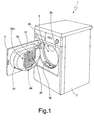
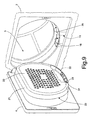
- number 1 indicates as a whole an electric household appliance, in particular a home laundry drier, substantially comprising a preferably, though not necessarily, parallelepiped-shaped casing 2; a drum 3 for housing the laundry to be dried, and which is housed in axially rotating manner and preferably, though not necessarily, horizontally inside casing 2, directly facing a laundry loading/unloading opening 2a formed in the front face of casing 2; a door 4 hinged to the front face of casing 2 to rotate to and from a work position closing opening 2a in the front face and sealing drum 3; and an open-circuit, hot-air generator 5 housed inside casing 2 to circulate hot, dry air inside drum 3 and over the laundry inside the drum to dry the laundry rapidly.
- a home laundry drier substantially comprising a preferably, though not necessarily, parallelepiped-shaped casing 2; a drum 3 for housing the laundry to be dried, and which is housed in axially rotating manner and preferably, though not necessarily, horizontally inside casing 2, directly facing a laundry
- Drier 1 also comprises an electric motor 7 or similar for rotating drum 3 about its longitudinal axis L, preferably, though not necessarily, inside a drying tub 6 housed inside casing 2.
- longitudinal axis L coincides with the longitudinal axis of drying tub 6.
- hot-air generator 5 provides for gradually drawing in air from outside drum 3; heating the drawn-in air to a predetermined temperature; and drawing the damp air out of drum 3.
- hot-air generator 5 provides for continually drawing in outside air, heating and feeding it into drum 3 to rapidly dry the laundry inside the drum, and exhausting the damp air from drum 3.
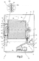
- Hot-air generator 5 substantially comprises: an air intake manifold 8 having a first end connected to the rear wall of drum 3, and a second end connected to an air inlet 9 formed preferably, though not necessarily, in casing 2; an electric heating element 10 (in the example shown, a resistor) located along intake manifold 8 to rapidly heat the airflow through inlet 9; an exhaust manifold 11 having a first end connected preferably, though not necessarily, to the front wall of drum 3, and a second end connected to an exhaust outlet 12 preferably, though not necessarily, in the front face of casing 2; and a centrifugal fan 13 located along exhaust manifold 11 to produce, inside intake manifold 8 and exhaust manifold 11, an airflow, which flows through drum 3 and over the laundry inside the drum, and is exhausted to the outside.
- an electric heating element 10 in the example shown, a resistor
- Centrifugal fan 13 is connected by a drive mechanism (shown by the dash line) to electric motor 7, which rotates both fan 13 and drum 3 about respective axes of rotation as a function of control signals Sp generated by a control unit 14 during a user-selected drying cycle.
- Drier 1 also comprises a steam generator 15, which, as a function of control signals Sp generated by control unit 14, feeds a steam jet into drum 3 to eliminate or at any rate greatly reduce creasing of the fabrics during the drying cycle.
- a steam generator 15 which, as a function of control signals Sp generated by control unit 14, feeds a steam jet into drum 3 to eliminate or at any rate greatly reduce creasing of the fabrics during the drying cycle.
- exhaust manifold 11 comprises a first manifold portion 16 extending inside casing 2; and a second manifold portion 17 fixed stably to door 4 and designed to connect to first portion 16, when door 4 closes opening 2a, to connect first portion 16 to drum 3.
- first manifold portion 16 preferably, though not necessarily, extends inside the front wall of casing 2, and has one end, i.e. its outlet, connected to exhaust outlet 12, and the opposite end, i.e. its inlet, connected to an opening 18 formed in an annular portion 35 of casing 2 defining the peripheral edge of opening 2a of drier 1 for housing door 4.
- centrifugal fan 13 is located along first manifold portion 16, downstream from second portion 17 along the air/steam flow path from drum 3 to exhaust outlet 12.
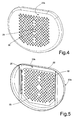
- Second portion 17 of exhaust manifold 11 is defined by a substantially cylindrical box member or shell 21, which projects from the inner face of door 4, extends through opening 2a, and projects partly inside drum 3.
- shell 21 comprises a front wall 22 positioned facing drum 3 when door 4 closes opening 2a, and in turn comprising a perforated central portion 22a through which the air/steam in drum 3 flows to the inlet of exhaust manifold 11.
- the lateral wall 23 of shell 21 has a slit 24 which, when door 4 closes opening 2a, is positioned facing opening 18 to connect second manifold portion 17 to the inlet of first manifold portion 16, and so allow the air/steam flowing along second portion 17 to flow freely into first portion 16 and out to the outside.
- hot-air generators Unlike known open-circuit, hot-air generators, open-circuit, hot-air generator 5 of drier 1 comprises shutter means 30 for selectively opening/closing exhaust manifold 11 ( Figures 2 , 3 ) to allow/prevent free outflow of the air/steam from drum 3.
- shutter means 30 selectively close exhaust manifold 11 at the crease-removing stage to prevent the steam inside drum 3 from flowing freely along exhaust manifold 11 to the outside ( Figure 3 ).
- shutter means 30 comprise a shutter plate 25 mounted on the inner surface 22b of front wall 22 to move between an open position (shown schematically in Figure 2 ) - in which the air/steam in drum 3 flows freely through perforated portion 22a of front wall 22 into exhaust manifold 11 - and a closed position (shown schematically in Figure 3 ) - in which the holes in central perforated portion 22a are closed completely to prevent the air/steam in drum 3 from flowing freely to the outside along exhaust manifold 11.
- shutter plate 25 is fitted movably to inner surface 22b of front wall 22, and is defined by a plate having a number of central holes which, when shutter plate 25 is in the open position, are aligned with the holes in perforated portion 22a of front wall 22.
- shutter plate 25 is mounted to slide along two lateral rails 26 on the inner surface of front wall 22, and has a central operating tab 36 projecting towards drum 3 through a slot formed through front wall 22, to allow the user to move shutter plate 25 manually between the open and closed position.
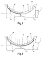
- shutter means 30 comprise a flap 32 fitted, at opening 18, to annular portion 35 of casing 2 defining the inner peripheral edge of opening 2a of drier 1, and which slides between an open position (shown schematically in Figures 6 , 7 ) allowing free air/steam flow from drum 3 to exhaust manifold 11, and a closed position (shown schematically in Figure 8 ) closing opening 18 to prevent air/steam flow from drum 3 to exhaust manifold 11.
- flap 32 seals opening 18 to prevent free air/steam flow from second portion 17 to first portion 16; whereas, in the open position, flap 32 is shifted to the side of opening 18 to fully open and connect opening 18 to slit 24 in shell 21, and so allow free air/steam flow from second portion 17 to first portion 16 of the exhaust manifold.
- shutter means 30 comprise a flap 33 fitted, at slit 24, to lateral wall 23 of shell 21, and which slides between an open position opening slit 24 and allowing free air/steam flow from drum 3 to exhaust manifold 11, and a closed position closing slit 24 to prevent air/steam flow from drum 3 to first portion 16 of exhaust manifold 11.
- flap 33 seals slit 24; whereas, in the open position, flap 33 is positioned, on lateral wall 23 of shell 21, to the side of slit 24 to fully open and connect slit 24 to opening 18 in annular portion 35 of casing 2.
- hot-air generator 5 may comprise a sensor 31 ( Figures 2 , 3 , 7, 8 ) for determining the open/closed position of shutter means 30, and which, on detecting a closed position of shutter means 30, prevents control unit 14 from activating a drying cycle, and conversely, on detecting an open position of shutter means 30, prevents control unit 14 from activating a crease-removing cycle.
- sensor 31 may conveniently comprise a microswitch, which switches from one on/off state to the other when shutter means 30 are set to the open or closed position.
- sensor 31 is located on wall 22 of shell 21, and is switched by shutter plate 25 moving into a given open/closed position.
- sensor 31 is located on annular portion 35, and is switched by flap 32 moving into a given open/closed position; and, in the Figure 9 example, sensor 31 is located on lateral wall 23 of shell 21, and is switched by flap 33 moving into a given open/closed position. Sensor 31 may obviously also be located directly on flap 33 or in any other position in which it is switched by a change in position of flap 33.
- control unit 14 determines whether or not shutter means 30 are in the open position, and, if they are not, disables the user-set drying cycle.
- control unit 14 activates hot-air generator 5 and, simultaneously, electric motor 7, which rotates drum 3 and centrifugal fan 13, which expels the damp air along the, in this case, fully open exhaust manifold 11.
- the user sets shutter means 30 to the closed position closing exhaust manifold 11, and activates a crease-removing cycle using selector means (not shown).
- control unit 14 determines whether or not shutter means 30 are in the closed position, and, if they are not, disables the user-set crease-removing cycle.
- control unit 14 activates steam generator 15 and, simultaneously, electric motor 7, which rotates both drum 3 and centrifugal fan 13, which, in this case, expels no steam from the drying tub, by virtue of exhaust manifold 11 being closed.
- the drier described has the major advantage of employing a single electric motor for driving both the ventilation device and the laundry drum, thus maintaining the cost-saving advantages of known driers with an open-circuit, hot-air generator, while at the same time implementing the crease-removing function in an extremely straightforward manner, with no immediate steam exhaust from laundry drum 3, even with the fan running.
- sensor 31 safeguards against user selection and activation of drying or crease-removing cycles incompatible with the position of shutter means 30.
Landscapes
- Engineering & Computer Science (AREA)
- Textile Engineering (AREA)
- Detail Structures Of Washing Machines And Dryers (AREA)
- Food-Manufacturing Devices (AREA)
- Filters For Electric Vacuum Cleaners (AREA)
- Control Of Throttle Valves Provided In The Intake System Or In The Exhaust System (AREA)
- Gyroscopes (AREA)
- Led Devices (AREA)
Priority Applications (10)
| Application Number | Priority Date | Filing Date | Title |
|---|---|---|---|
| EP07108567A EP1995371B1 (fr) | 2007-05-21 | 2007-05-21 | Appareil ménager électrique |
| AT07108567T ATE448350T1 (de) | 2007-05-21 | 2007-05-21 | Elektrisches haushaltsgerät |
| DE602007003199T DE602007003199D1 (de) | 2007-05-21 | 2007-05-21 | Elektrisches Haushaltsgerät |
| PL07108567T PL1995371T3 (pl) | 2007-05-21 | 2007-05-21 | Sprzęt gospodarstwa domowego |
| ES07108567T ES2334465T3 (es) | 2007-05-21 | 2007-05-21 | Aparato electrodomestico. |
| MX2009012301A MX2009012301A (es) | 2007-05-21 | 2008-05-13 | Electrodomestico. |
| BRPI0811602-4A BRPI0811602A2 (pt) | 2007-05-21 | 2008-05-13 | Aparelho eletrodoméstico |
| US12/593,950 US8272144B2 (en) | 2007-05-21 | 2008-05-13 | Electric household appliance |
| PCT/EP2008/003811 WO2008141750A1 (fr) | 2007-05-21 | 2008-05-13 | Appareil électroménager |
| CN2008800136771A CN101668892B (zh) | 2007-05-21 | 2008-05-13 | 家用电器 |
Applications Claiming Priority (1)
| Application Number | Priority Date | Filing Date | Title |
|---|---|---|---|
| EP07108567A EP1995371B1 (fr) | 2007-05-21 | 2007-05-21 | Appareil ménager électrique |
Publications (2)
| Publication Number | Publication Date |
|---|---|
| EP1995371A1 true EP1995371A1 (fr) | 2008-11-26 |
| EP1995371B1 EP1995371B1 (fr) | 2009-11-11 |
Family
ID=38651249
Family Applications (1)
| Application Number | Title | Priority Date | Filing Date |
|---|---|---|---|
| EP07108567A Not-in-force EP1995371B1 (fr) | 2007-05-21 | 2007-05-21 | Appareil ménager électrique |
Country Status (10)
| Country | Link |
|---|---|
| US (1) | US8272144B2 (fr) |
| EP (1) | EP1995371B1 (fr) |
| CN (1) | CN101668892B (fr) |
| AT (1) | ATE448350T1 (fr) |
| BR (1) | BRPI0811602A2 (fr) |
| DE (1) | DE602007003199D1 (fr) |
| ES (1) | ES2334465T3 (fr) |
| MX (1) | MX2009012301A (fr) |
| PL (1) | PL1995371T3 (fr) |
| WO (1) | WO2008141750A1 (fr) |
Cited By (2)
| Publication number | Priority date | Publication date | Assignee | Title |
|---|---|---|---|---|
| US20110041353A1 (en) * | 2008-04-29 | 2011-02-24 | BSH Bosch und Siemens Hausgeräte GmbH | Vented dryer having counter-flowing air and method for the operation thereof |
| EP2642012A1 (fr) | 2012-03-22 | 2013-09-25 | Electrolux Home Products Corporation N.V. | Machine à laver le linge et procédé de traitement de linge dans un lave-linge |
Families Citing this family (8)
| Publication number | Priority date | Publication date | Assignee | Title |
|---|---|---|---|---|
| DE102007007354B4 (de) | 2006-02-20 | 2013-10-10 | Lg Electronics Inc. | Wäschetrockner und Verfahren zur Steuerung |
| KR100830514B1 (ko) | 2006-06-12 | 2008-05-21 | 엘지전자 주식회사 | 건조기 및 그 제어방법 |
| US7997006B2 (en) * | 2007-01-12 | 2011-08-16 | Lg Electronics Inc. | Laundry machine and control method thereof |
| US8104191B2 (en) | 2008-07-31 | 2012-01-31 | Electrolux Home Products, Inc. | Laundry dryer providing moisture application during tumbling and reduced airflow |
| WO2010114332A2 (fr) * | 2009-04-02 | 2010-10-07 | (주)엘지전자 | Sèche-linge doté d'un générateur de vapeur utilisant un réchauffeur d'air chaud |
| US9109317B2 (en) | 2009-08-21 | 2015-08-18 | Whirlpool Corporation | Controlled moisture removal in a laundry treating appliance |
| CN107366143A (zh) * | 2017-09-14 | 2017-11-21 | 无锡市强力干燥设备厂 | 衣物滚筒烘干机 |
| US20190218701A1 (en) * | 2018-01-12 | 2019-07-18 | Whirlpool Corporation | Laundry treating appliance with vent |
Citations (7)
| Publication number | Priority date | Publication date | Assignee | Title |
|---|---|---|---|---|
| US2873539A (en) * | 1958-02-27 | 1959-02-17 | Gen Electric | Clothes dryer with clothes odorizing means |
| GB2143935A (en) * | 1983-07-25 | 1985-02-20 | Hotpoint Ltd | Tumbler dryer |
| GB2346678A (en) * | 1998-12-23 | 2000-08-16 | Electrolux Zanussi Elettrodome | Rotary drum drier with door having a dispenser containing co-adjuvant substances |
| EP1441058A1 (fr) * | 2003-01-25 | 2004-07-28 | Electrolux Home Products Corporation N.V. | Sèche-linge avec un mode de circulation d'air et procédé de traitement du linge |
| EP1666655A2 (fr) * | 2004-12-02 | 2006-06-07 | Samsung Electronics Co., Ltd. | Élimination des plis dans le linge |
| WO2006101358A1 (fr) * | 2005-03-25 | 2006-09-28 | Lg Electronics Inc. | Machine a laver |
| US20070006484A1 (en) * | 2002-12-20 | 2007-01-11 | Harald Moschuetz | Clothes dryer and method for removing odours from textiles |
Family Cites Families (7)
| Publication number | Priority date | Publication date | Assignee | Title |
|---|---|---|---|---|
| BE623069A (fr) * | 1961-10-03 | |||
| US3544207A (en) * | 1968-01-03 | 1970-12-01 | Bell & Howell Co | Shutter control mechanism |
| JPS6429295A (en) * | 1987-07-27 | 1989-01-31 | Matsushita Seiko Kk | Small clothing drying case |
| DE10302866B4 (de) | 2003-01-25 | 2010-08-12 | Electrolux Home Products Corporation N.V. | Wäschetrockner mit einer Einrichtung zum Einsprühen von Zusätzen und Verfahren hierfür |
| US7171821B2 (en) * | 2004-04-30 | 2007-02-06 | Thermo King Corporation | Temperature control unit having a vent arrangement |
| KR100717457B1 (ko) * | 2004-10-22 | 2007-05-14 | 엘지전자 주식회사 | 드럼 세탁기 |
| EP1885937A4 (fr) * | 2005-05-23 | 2013-11-20 | Ahn Byung Hwan | Sechoir et son procede de commande |
-
2007
- 2007-05-21 AT AT07108567T patent/ATE448350T1/de not_active IP Right Cessation
- 2007-05-21 DE DE602007003199T patent/DE602007003199D1/de active Active
- 2007-05-21 PL PL07108567T patent/PL1995371T3/pl unknown
- 2007-05-21 EP EP07108567A patent/EP1995371B1/fr not_active Not-in-force
- 2007-05-21 ES ES07108567T patent/ES2334465T3/es active Active
-
2008
- 2008-05-13 US US12/593,950 patent/US8272144B2/en active Active
- 2008-05-13 CN CN2008800136771A patent/CN101668892B/zh not_active Expired - Fee Related
- 2008-05-13 WO PCT/EP2008/003811 patent/WO2008141750A1/fr active Application Filing
- 2008-05-13 MX MX2009012301A patent/MX2009012301A/es active IP Right Grant
- 2008-05-13 BR BRPI0811602-4A patent/BRPI0811602A2/pt not_active IP Right Cessation
Patent Citations (7)
| Publication number | Priority date | Publication date | Assignee | Title |
|---|---|---|---|---|
| US2873539A (en) * | 1958-02-27 | 1959-02-17 | Gen Electric | Clothes dryer with clothes odorizing means |
| GB2143935A (en) * | 1983-07-25 | 1985-02-20 | Hotpoint Ltd | Tumbler dryer |
| GB2346678A (en) * | 1998-12-23 | 2000-08-16 | Electrolux Zanussi Elettrodome | Rotary drum drier with door having a dispenser containing co-adjuvant substances |
| US20070006484A1 (en) * | 2002-12-20 | 2007-01-11 | Harald Moschuetz | Clothes dryer and method for removing odours from textiles |
| EP1441058A1 (fr) * | 2003-01-25 | 2004-07-28 | Electrolux Home Products Corporation N.V. | Sèche-linge avec un mode de circulation d'air et procédé de traitement du linge |
| EP1666655A2 (fr) * | 2004-12-02 | 2006-06-07 | Samsung Electronics Co., Ltd. | Élimination des plis dans le linge |
| WO2006101358A1 (fr) * | 2005-03-25 | 2006-09-28 | Lg Electronics Inc. | Machine a laver |
Cited By (6)
| Publication number | Priority date | Publication date | Assignee | Title |
|---|---|---|---|---|
| US20110041353A1 (en) * | 2008-04-29 | 2011-02-24 | BSH Bosch und Siemens Hausgeräte GmbH | Vented dryer having counter-flowing air and method for the operation thereof |
| US8528226B2 (en) * | 2008-04-29 | 2013-09-10 | Bsh Bosch Und Siemens Hausgeraete Gmbh | Vented dryer having counter-flowing air and method for the operation thereof |
| EP2642012A1 (fr) | 2012-03-22 | 2013-09-25 | Electrolux Home Products Corporation N.V. | Machine à laver le linge et procédé de traitement de linge dans un lave-linge |
| WO2013139686A1 (fr) * | 2012-03-22 | 2013-09-26 | Electrolux Home Products Corporation N.V. | Machine de blanchisserie et procédé de traitement de linge dans une machine de blanchisserie |
| CN104204331A (zh) * | 2012-03-22 | 2014-12-10 | 伊莱克斯家用产品股份有限公司 | 洗衣机以及在洗衣机中进行衣物处理的方法 |
| CN104204331B (zh) * | 2012-03-22 | 2017-04-26 | 伊莱克斯家用产品股份有限公司 | 洗衣机以及在洗衣机中进行衣物处理的方法 |
Also Published As
| Publication number | Publication date |
|---|---|
| MX2009012301A (es) | 2009-12-03 |
| US20100115790A1 (en) | 2010-05-13 |
| ATE448350T1 (de) | 2009-11-15 |
| US8272144B2 (en) | 2012-09-25 |
| WO2008141750A1 (fr) | 2008-11-27 |
| PL1995371T3 (pl) | 2010-04-30 |
| CN101668892B (zh) | 2011-05-18 |
| DE602007003199D1 (de) | 2009-12-24 |
| EP1995371B1 (fr) | 2009-11-11 |
| BRPI0811602A2 (pt) | 2015-08-04 |
| ES2334465T3 (es) | 2010-03-10 |
| CN101668892A (zh) | 2010-03-10 |
Similar Documents
| Publication | Publication Date | Title |
|---|---|---|
| EP1995371B1 (fr) | Appareil ménager électrique | |
| KR100662473B1 (ko) | 스팀발생장치를 이용한 건조기 | |
| EP1951948B1 (fr) | Generateur de vapeur, sechoir a linge equipe de celui-ci et son procede de commande | |
| US8250777B2 (en) | Device of supplying water for laundry dryer and method for controlling the same | |
| EP2039823B1 (fr) | Machine de blanchisserie | |
| KR101328920B1 (ko) | 건조기 | |
| KR100866884B1 (ko) | 건조기의 포량 결정 제어방법 및 그 건조기 | |
| KR100640788B1 (ko) | 스팀발생기를 구비한 건조기 | |
| KR20090030899A (ko) | 세탁장치 | |
| KR20060061974A (ko) | 의류의 구김제거장치 및 그 방법 | |
| KR101208532B1 (ko) | 건조기 | |
| EP2634301B1 (fr) | Machine à laver et sécher le linge domestique avec un dispositif de condensation et prodédé de fonctionnement de cette machine | |
| KR100672439B1 (ko) | 스팀발생기를 구비한 건조기 | |
| KR100740836B1 (ko) | 스팀발생기를 구비한 건조기 | |
| KR100662472B1 (ko) | 스팀발생장치를 이용한 건조기 | |
| EP2280114B1 (fr) | Sèche-linge doté d'une buse d'injection de liquides | |
| KR100640811B1 (ko) | 건조기용 급수장치 및 그 제어방법 | |
| KR100672437B1 (ko) | 건조기용 스팀발생기 및 이를 이용한 건조기 | |
| KR100833866B1 (ko) | 스팀건조기 | |
| JP4383960B2 (ja) | 乾燥機能付き洗濯機 | |
| KR100672438B1 (ko) | 스팀발생기를 구비한 건조기 | |
| KR100734371B1 (ko) | 건조기 및 그 제어방법 | |
| JP5597373B2 (ja) | 衣類乾燥機 | |
| KR101208534B1 (ko) | 건조기 | |
| KR101015864B1 (ko) | 통합 히터가 구비된 드럼 세탁기 |
Legal Events
| Date | Code | Title | Description |
|---|---|---|---|
| PUAI | Public reference made under article 153(3) epc to a published international application that has entered the european phase |
Free format text: ORIGINAL CODE: 0009012 |
|
| AK | Designated contracting states |
Kind code of ref document: A1 Designated state(s): AT BE BG CH CY CZ DE DK EE ES FI FR GB GR HU IE IS IT LI LT LU LV MC MT NL PL PT RO SE SI SK TR |
|
| AX | Request for extension of the european patent |
Extension state: AL BA HR MK RS |
|
| GRAP | Despatch of communication of intention to grant a patent |
Free format text: ORIGINAL CODE: EPIDOSNIGR1 |
|
| 17P | Request for examination filed |
Effective date: 20090504 |
|
| AKX | Designation fees paid |
Designated state(s): AT BE BG CH CY CZ DE DK EE ES FI FR GB GR HU IE IS IT LI LT LU LV MC MT NL PL PT RO SE SI SK TR |
|
| GRAS | Grant fee paid |
Free format text: ORIGINAL CODE: EPIDOSNIGR3 |
|
| GRAA | (expected) grant |
Free format text: ORIGINAL CODE: 0009210 |
|
| AK | Designated contracting states |
Kind code of ref document: B1 Designated state(s): AT BE BG CH CY CZ DE DK EE ES FI FR GB GR HU IE IS IT LI LT LU LV MC MT NL PL PT RO SE SI SK TR |
|
| REG | Reference to a national code |
Ref country code: GB Ref legal event code: FG4D |
|
| REG | Reference to a national code |
Ref country code: CH Ref legal event code: EP |
|
| REG | Reference to a national code |
Ref country code: IE Ref legal event code: FG4D |
|
| REF | Corresponds to: |
Ref document number: 602007003199 Country of ref document: DE Date of ref document: 20091224 Kind code of ref document: P |
|
| REG | Reference to a national code |
Ref country code: ES Ref legal event code: FG2A Ref document number: 2334465 Country of ref document: ES Kind code of ref document: T3 |
|
| NLV1 | Nl: lapsed or annulled due to failure to fulfill the requirements of art. 29p and 29m of the patents act | ||
| LTIE | Lt: invalidation of european patent or patent extension |
Effective date: 20091111 |
|
| PG25 | Lapsed in a contracting state [announced via postgrant information from national office to epo] |
Ref country code: LT Free format text: LAPSE BECAUSE OF FAILURE TO SUBMIT A TRANSLATION OF THE DESCRIPTION OR TO PAY THE FEE WITHIN THE PRESCRIBED TIME-LIMIT Effective date: 20091111 Ref country code: PT Free format text: LAPSE BECAUSE OF FAILURE TO SUBMIT A TRANSLATION OF THE DESCRIPTION OR TO PAY THE FEE WITHIN THE PRESCRIBED TIME-LIMIT Effective date: 20100311 Ref country code: FI Free format text: LAPSE BECAUSE OF FAILURE TO SUBMIT A TRANSLATION OF THE DESCRIPTION OR TO PAY THE FEE WITHIN THE PRESCRIBED TIME-LIMIT Effective date: 20091111 Ref country code: SE Free format text: LAPSE BECAUSE OF FAILURE TO SUBMIT A TRANSLATION OF THE DESCRIPTION OR TO PAY THE FEE WITHIN THE PRESCRIBED TIME-LIMIT Effective date: 20091111 Ref country code: IS Free format text: LAPSE BECAUSE OF FAILURE TO SUBMIT A TRANSLATION OF THE DESCRIPTION OR TO PAY THE FEE WITHIN THE PRESCRIBED TIME-LIMIT Effective date: 20100311 |
|
| REG | Reference to a national code |
Ref country code: PL Ref legal event code: T3 |
|
| PG25 | Lapsed in a contracting state [announced via postgrant information from national office to epo] |
Ref country code: SI Free format text: LAPSE BECAUSE OF FAILURE TO SUBMIT A TRANSLATION OF THE DESCRIPTION OR TO PAY THE FEE WITHIN THE PRESCRIBED TIME-LIMIT Effective date: 20091111 Ref country code: CY Free format text: LAPSE BECAUSE OF FAILURE TO SUBMIT A TRANSLATION OF THE DESCRIPTION OR TO PAY THE FEE WITHIN THE PRESCRIBED TIME-LIMIT Effective date: 20091111 Ref country code: LV Free format text: LAPSE BECAUSE OF FAILURE TO SUBMIT A TRANSLATION OF THE DESCRIPTION OR TO PAY THE FEE WITHIN THE PRESCRIBED TIME-LIMIT Effective date: 20091111 |
|
| PG25 | Lapsed in a contracting state [announced via postgrant information from national office to epo] |
Ref country code: AT Free format text: LAPSE BECAUSE OF FAILURE TO SUBMIT A TRANSLATION OF THE DESCRIPTION OR TO PAY THE FEE WITHIN THE PRESCRIBED TIME-LIMIT Effective date: 20091111 Ref country code: BE Free format text: LAPSE BECAUSE OF FAILURE TO SUBMIT A TRANSLATION OF THE DESCRIPTION OR TO PAY THE FEE WITHIN THE PRESCRIBED TIME-LIMIT Effective date: 20091111 |
|
| PG25 | Lapsed in a contracting state [announced via postgrant information from national office to epo] |
Ref country code: EE Free format text: LAPSE BECAUSE OF FAILURE TO SUBMIT A TRANSLATION OF THE DESCRIPTION OR TO PAY THE FEE WITHIN THE PRESCRIBED TIME-LIMIT Effective date: 20091111 Ref country code: DK Free format text: LAPSE BECAUSE OF FAILURE TO SUBMIT A TRANSLATION OF THE DESCRIPTION OR TO PAY THE FEE WITHIN THE PRESCRIBED TIME-LIMIT Effective date: 20091111 Ref country code: BG Free format text: LAPSE BECAUSE OF FAILURE TO SUBMIT A TRANSLATION OF THE DESCRIPTION OR TO PAY THE FEE WITHIN THE PRESCRIBED TIME-LIMIT Effective date: 20100211 Ref country code: RO Free format text: LAPSE BECAUSE OF FAILURE TO SUBMIT A TRANSLATION OF THE DESCRIPTION OR TO PAY THE FEE WITHIN THE PRESCRIBED TIME-LIMIT Effective date: 20091111 |
|
| PG25 | Lapsed in a contracting state [announced via postgrant information from national office to epo] |
Ref country code: SK Free format text: LAPSE BECAUSE OF FAILURE TO SUBMIT A TRANSLATION OF THE DESCRIPTION OR TO PAY THE FEE WITHIN THE PRESCRIBED TIME-LIMIT Effective date: 20091111 Ref country code: CZ Free format text: LAPSE BECAUSE OF FAILURE TO SUBMIT A TRANSLATION OF THE DESCRIPTION OR TO PAY THE FEE WITHIN THE PRESCRIBED TIME-LIMIT Effective date: 20091111 |
|
| PLBE | No opposition filed within time limit |
Free format text: ORIGINAL CODE: 0009261 |
|
| STAA | Information on the status of an ep patent application or granted ep patent |
Free format text: STATUS: NO OPPOSITION FILED WITHIN TIME LIMIT |
|
| 26N | No opposition filed |
Effective date: 20100812 |
|
| PG25 | Lapsed in a contracting state [announced via postgrant information from national office to epo] |
Ref country code: GR Free format text: LAPSE BECAUSE OF FAILURE TO SUBMIT A TRANSLATION OF THE DESCRIPTION OR TO PAY THE FEE WITHIN THE PRESCRIBED TIME-LIMIT Effective date: 20100212 |
|
| PG25 | Lapsed in a contracting state [announced via postgrant information from national office to epo] |
Ref country code: MC Free format text: LAPSE BECAUSE OF NON-PAYMENT OF DUE FEES Effective date: 20100531 |
|
| PG25 | Lapsed in a contracting state [announced via postgrant information from national office to epo] |
Ref country code: IT Free format text: LAPSE BECAUSE OF NON-PAYMENT OF DUE FEES Effective date: 20100521 |
|
| PG25 | Lapsed in a contracting state [announced via postgrant information from national office to epo] |
Ref country code: IE Free format text: LAPSE BECAUSE OF NON-PAYMENT OF DUE FEES Effective date: 20100521 Ref country code: MT Free format text: LAPSE BECAUSE OF FAILURE TO SUBMIT A TRANSLATION OF THE DESCRIPTION OR TO PAY THE FEE WITHIN THE PRESCRIBED TIME-LIMIT Effective date: 20091111 |
|
| REG | Reference to a national code |
Ref country code: CH Ref legal event code: PL |
|
| PG25 | Lapsed in a contracting state [announced via postgrant information from national office to epo] |
Ref country code: LI Free format text: LAPSE BECAUSE OF NON-PAYMENT OF DUE FEES Effective date: 20110531 Ref country code: CH Free format text: LAPSE BECAUSE OF NON-PAYMENT OF DUE FEES Effective date: 20110531 |
|
| REG | Reference to a national code |
Ref country code: FR Ref legal event code: CA Effective date: 20120116 |
|
| PG25 | Lapsed in a contracting state [announced via postgrant information from national office to epo] |
Ref country code: LU Free format text: LAPSE BECAUSE OF NON-PAYMENT OF DUE FEES Effective date: 20100521 Ref country code: NL Free format text: LAPSE BECAUSE OF FAILURE TO SUBMIT A TRANSLATION OF THE DESCRIPTION OR TO PAY THE FEE WITHIN THE PRESCRIBED TIME-LIMIT Effective date: 20091111 Ref country code: HU Free format text: LAPSE BECAUSE OF FAILURE TO SUBMIT A TRANSLATION OF THE DESCRIPTION OR TO PAY THE FEE WITHIN THE PRESCRIBED TIME-LIMIT Effective date: 20100512 |
|
| PG25 | Lapsed in a contracting state [announced via postgrant information from national office to epo] |
Ref country code: TR Free format text: LAPSE BECAUSE OF FAILURE TO SUBMIT A TRANSLATION OF THE DESCRIPTION OR TO PAY THE FEE WITHIN THE PRESCRIBED TIME-LIMIT Effective date: 20091111 |
|
| PGFP | Annual fee paid to national office [announced via postgrant information from national office to epo] |
Ref country code: ES Payment date: 20120525 Year of fee payment: 6 |
|
| PGFP | Annual fee paid to national office [announced via postgrant information from national office to epo] |
Ref country code: GB Payment date: 20130521 Year of fee payment: 7 Ref country code: DE Payment date: 20130522 Year of fee payment: 7 |
|
| PGFP | Annual fee paid to national office [announced via postgrant information from national office to epo] |
Ref country code: IT Payment date: 20130530 Year of fee payment: 7 Ref country code: FR Payment date: 20130603 Year of fee payment: 7 Ref country code: PL Payment date: 20130425 Year of fee payment: 7 |
|
| REG | Reference to a national code |
Ref country code: DE Ref legal event code: R119 Ref document number: 602007003199 Country of ref document: DE |
|
| GBPC | Gb: european patent ceased through non-payment of renewal fee |
Effective date: 20140521 |
|
| REG | Reference to a national code |
Ref country code: FR Ref legal event code: ST Effective date: 20150130 |
|
| REG | Reference to a national code |
Ref country code: DE Ref legal event code: R119 Ref document number: 602007003199 Country of ref document: DE Effective date: 20141202 |
|
| PG25 | Lapsed in a contracting state [announced via postgrant information from national office to epo] |
Ref country code: IT Free format text: LAPSE BECAUSE OF NON-PAYMENT OF DUE FEES Effective date: 20140521 Ref country code: DE Free format text: LAPSE BECAUSE OF NON-PAYMENT OF DUE FEES Effective date: 20141202 |
|
| PG25 | Lapsed in a contracting state [announced via postgrant information from national office to epo] |
Ref country code: FR Free format text: LAPSE BECAUSE OF NON-PAYMENT OF DUE FEES Effective date: 20140602 Ref country code: GB Free format text: LAPSE BECAUSE OF NON-PAYMENT OF DUE FEES Effective date: 20140521 |
|
| PG25 | Lapsed in a contracting state [announced via postgrant information from national office to epo] |
Ref country code: PL Free format text: LAPSE BECAUSE OF NON-PAYMENT OF DUE FEES Effective date: 20140521 |
|
| REG | Reference to a national code |
Ref country code: PL Ref legal event code: LAPE |
|
| REG | Reference to a national code |
Ref country code: ES Ref legal event code: FD2A Effective date: 20160205 |
|
| PG25 | Lapsed in a contracting state [announced via postgrant information from national office to epo] |
Ref country code: ES Free format text: LAPSE BECAUSE OF NON-PAYMENT OF DUE FEES Effective date: 20140522 |