EP1995335B1 - Process for manufacturing metal member, and structural member - Google Patents
Process for manufacturing metal member, and structural member Download PDFInfo
- Publication number
- EP1995335B1 EP1995335B1 EP07738611.8A EP07738611A EP1995335B1 EP 1995335 B1 EP1995335 B1 EP 1995335B1 EP 07738611 A EP07738611 A EP 07738611A EP 1995335 B1 EP1995335 B1 EP 1995335B1
- Authority
- EP
- European Patent Office
- Prior art keywords
- shot peening
- shot
- metallic
- surface roughness
- producing
- Prior art date
- Legal status (The legal status is an assumption and is not a legal conclusion. Google has not performed a legal analysis and makes no representation as to the accuracy of the status listed.)
- Expired - Fee Related
Links
Images


Classifications
-
- B—PERFORMING OPERATIONS; TRANSPORTING
- B24—GRINDING; POLISHING
- B24C—ABRASIVE OR RELATED BLASTING WITH PARTICULATE MATERIAL
- B24C1/00—Methods for use of abrasive blasting for producing particular effects; Use of auxiliary equipment in connection with such methods
- B24C1/10—Methods for use of abrasive blasting for producing particular effects; Use of auxiliary equipment in connection with such methods for compacting surfaces, e.g. shot-peening
-
- B—PERFORMING OPERATIONS; TRANSPORTING
- B24—GRINDING; POLISHING
- B24C—ABRASIVE OR RELATED BLASTING WITH PARTICULATE MATERIAL
- B24C11/00—Selection of abrasive materials or additives for abrasive blasts
-
- C—CHEMISTRY; METALLURGY
- C21—METALLURGY OF IRON
- C21D—MODIFYING THE PHYSICAL STRUCTURE OF FERROUS METALS; GENERAL DEVICES FOR HEAT TREATMENT OF FERROUS OR NON-FERROUS METALS OR ALLOYS; MAKING METAL MALLEABLE, e.g. BY DECARBURISATION OR TEMPERING
- C21D7/00—Modifying the physical properties of iron or steel by deformation
- C21D7/02—Modifying the physical properties of iron or steel by deformation by cold working
- C21D7/04—Modifying the physical properties of iron or steel by deformation by cold working of the surface
- C21D7/06—Modifying the physical properties of iron or steel by deformation by cold working of the surface by shot-peening or the like
-
- Y—GENERAL TAGGING OF NEW TECHNOLOGICAL DEVELOPMENTS; GENERAL TAGGING OF CROSS-SECTIONAL TECHNOLOGIES SPANNING OVER SEVERAL SECTIONS OF THE IPC; TECHNICAL SUBJECTS COVERED BY FORMER USPC CROSS-REFERENCE ART COLLECTIONS [XRACs] AND DIGESTS
- Y10—TECHNICAL SUBJECTS COVERED BY FORMER USPC
- Y10T—TECHNICAL SUBJECTS COVERED BY FORMER US CLASSIFICATION
- Y10T29/00—Metal working
- Y10T29/47—Burnishing
- Y10T29/479—Burnishing by shot peening or blasting
-
- Y—GENERAL TAGGING OF NEW TECHNOLOGICAL DEVELOPMENTS; GENERAL TAGGING OF CROSS-SECTIONAL TECHNOLOGIES SPANNING OVER SEVERAL SECTIONS OF THE IPC; TECHNICAL SUBJECTS COVERED BY FORMER USPC CROSS-REFERENCE ART COLLECTIONS [XRACs] AND DIGESTS
- Y10—TECHNICAL SUBJECTS COVERED BY FORMER USPC
- Y10T—TECHNICAL SUBJECTS COVERED BY FORMER US CLASSIFICATION
- Y10T428/00—Stock material or miscellaneous articles
- Y10T428/12—All metal or with adjacent metals
- Y10T428/12993—Surface feature [e.g., rough, mirror]
Definitions
- the present invention relates to a process for producing a metallic component having improved fatigue properties and a structural member.
- Shot peening represents a known example of a surface modification process that is used for enhancing the fatigue strength of metallic materials such as the structural members used in aircraft and automobiles and the like (see Non Patent Citation 1).
- Shot peening is a method in which, by blasting countless particles having a particle size of around 0.8 mm (the shot material) together with a stream of compressed air onto the surface of a metallic material, the hardness of the metallic material surface is increased, and a layer having compressive residual stress is formed at a certain depth.
- Non Patent Citation 1 T. Dorr and four others, "Influence of Shot Penning on Fatigue Performance of High-Strength Aluminum- and Magnesium Alloys", The 7th International Conference on Shot Peening, 1999, Institute of Precision Mechanics, Warsaw, Tru. Internet ⁇ URL: http://www.shotpeening.org/ICSP/icsp-7-20.pdf>
- shot peening increases the surface roughness of the member, meaning the prescribed surface roughness required for a particular application may not always be attainable. Furthermore, because of the increase in surface roughness and the effect of flaws generated on the surface of the member by the shot, a partial reduction in the degree of improvement in fatigue properties achieved by shot peening is unavoidable. A process that enables the fatigue properties of a member to be enhanced by shot peening while suppressing any increase in the surface roughness of the member or any flaw generation has yet to be discovered.
- flapper peening does not induce a high level of compressive residual stress, and as a result, satisfactory fatigue properties cannot be obtained. Furthermore, cold working processes require post-processing, meaning the process is more complex.
- shot peening may also cause plastic deformation of the surface layer of the member, which can cause deformation problems such as bending.
- these types of problems have typically been prevented by using a tape or film-like pressure-sensitive adhesive mask to cover those areas of the material for which deformation such as bending or an increase in the surface roughness is likely to be problematic prior to shot peening.
- attaching and then removing a pressure-sensitive adhesive mask requires considerable effort, and results in extra costs.
- edges of metallic components must be chamfered or rounded prior to shot peening in order to prevent the generation of such burrs.
- chamfering or rounding of the edges is typically performed manually, meaning the efficiency is poor.
- the present invention has been developed in light of these circumstances, and has an object of providing a process for producing a metallic component of a structural member or the like used in an aircraft or automobile or the like, the process comprising shot peening the surface of a metallic material, wherein the fatigue properties of the metallic material can be improved with almost no variation in the surface roughness over the course of shot peening.
- the present invention also has an object of providing a process for producing a metallic component of a structural member or the like used in an aircraft or automobile or the like, the process comprising shot peening the surface of a metallic material, wherein by reducing deformation of the metallic material and suppressing increases in the surface roughness, covering of the metallic material surface becomes unnecessary, and the metallic component can be produced at a reduced cost.
- the present invention also has an object of providing a process for producing a metallic component of a structural member or the like used in an aircraft or automobile or the like, the process comprising shot peening the surface of a metallic material, wherein chamfering or rounding of edges prior to shot peening is unnecessary, enabling reductions in the number of process steps and the production costs.
- JP 2002-285237 A discloses a process for producing a cold-rolled steel sheet including a step of adjusting a surface roughness by projecting solid particles on the surface of the cold-rolled steel sheet after being subjected to a cold rolling, annealing and temper rolling, wherein the mean particle size of the solid particles is 30-300 ⁇ m and the solid particles are projected by a centrifugal projector of which the projection distance is ⁇ 700 mm.
- JP 2003-170353 A JP 2004-346424 A , JP2005-248259 A and JP 2005-264331 A .
- the present invention provides a process for producing a metallic component according to claim 1.
- a metallic component having improved fatigue properties can be produced with small change in the surface roughness of the metallic material.
- the surface roughness represented by the arithmetic mean roughness Ra is referred to as simply "the surface roughness”.
- the "average particle size” is determined as the particle size corresponding with the peak in a frequency distribution curve, and is also referred to as the most frequent particle size or the modal diameter. Alternatively, the average particle size may also be determined using the methods listed below.
- the surface roughness of the metallic material prior to the projection step is preferably not less than 0.7 ⁇ m and not more than 65 ⁇ m.
- the surface roughness of the metallic material prior to the projection step is less than 0.7 ⁇ m, then the ratio of the surface roughness of the metallic material surface following the projection step relative to the surface roughness prior to the projection step tends to increase, and the effect of the present invention in improving the fatigue properties tends to diminish, which is undesirable.
- the absolute value of the compressive residual stress at the metallic material surface following the projection step is preferably not less than 150 MPa.
- projection of the particles onto the surface of the metallic material may be performed without using the type of mask that is attached to the surface of a metallic material during conventional shot peening in order to prevent increases in the surface roughness or deformation of the metallic material.
- the process for producing a metallic component of the present invention in addition to the fact that the surface roughness of the metallic material undergoes almost no change over the course of the projection step, almost no deformation such as bending occurs on the metallic material, meaning the type of pressure-sensitive adhesive mask used in conventional shot peening is unnecessary, and as a result, the steps of attaching and removing the pressure-sensitive adhesive mask are also unnecessary, enabling a dramatic reduction in the number of process steps and the production costs for the metallic components.
- a structural member of the present invention includes a metallic component produced using one of the production processes described above.
- This structural member has excellent fatigue properties, and has no deformation such as bending and no excessive surface roughness. Furthermore, because production can be performed without the need for covering with a pressure-sensitive adhesive mask and without chamfering or rounding of the edges, the structural member can be produced at a reduced cost. This structural member can be used favorably in the field of transportation machinery such as aircraft and automobiles, and in other fields that require favorable material fatigue properties.
- the present invention provides a process for producing a metallic component of a structural member or the like used in an aircraft or automobile or the like, the process comprising shot peening the surface of a metallic material, wherein the fatigue properties of the metallic material can be improved with almost no variation in the surface roughness over the course of shot peening.
- the present invention also provides a process for producing a metallic component of a structural member or the like used in an aircraft or automobile or the like, the process comprising shot peening the surface of a metallic material, wherein by reducing deformation of the metallic material and suppressing increases in the surface roughness, covering of the metallic material surface becomes unnecessary, and the metallic component can be produced at a reduced cost.
- the present invention also provides a process for producing a metallic component of a structural member or the like used in an aircraft or automobile or the like, the process comprising shot peening the surface of a metallic material, wherein chamfering or rounding of edges prior to shot peening is unnecessary, enabling reductions in the number of process steps and the production costs.
- a lightweight alloy material or steel material is used.
- the lightweight alloy include aluminum alloys and titanium alloys.
- the particles (the shot material) used in shot peening the metallic material are hard particles of a metal, ceramic or glass or the like, and are preferably ceramic particles such as alumina or silica particles.
- a shot material with a particle size of around 0.8 mm is used, but in the present invention, a shot material with an average particle size of not more than 200 ⁇ m is used.
- the average particle size of the shot material is preferably not less than 10 ⁇ m and not more than 200 ⁇ m, and is even more preferably not less than 30 ⁇ m and not more than 100 ⁇ m. If the average particle size of the shot material particles is greater than 200 ⁇ m, then the excessively large kinetic energy of the particles causes damage to the material surface, meaning a satisfactory improvement in the fatigue life cannot be achieved. Furthermore, if the average particle size of the shot material particles is smaller than 10 ⁇ m, then blockages and the like of the shot material mean achieving a stable spray state is very difficult.
- the shot velocity of the shot material is regulated by the air pressure of the compressed air stream.
- the air pressure is preferably not less than 0.1 MPa and not more than 1 MPa, and is even more preferably not less than 0.3 MPa and not more than 0.6 MPa. If the air pressure is greater than 1 MPa, then the excessively large kinetic energy of the particles causes damage to the material surface, meaning a satisfactory improvement in the fatigue life cannot be achieved. Furthermore, if the air pressure is less than 0.1 MPa, then achieving a stable spray state becomes very difficult.
- the shot material particles are preferably spherical in shape.
- the reason for this preference is that if the shot material particles are sharp, then the surface of the metallic component may become damaged.
- the coverage by shot peening is preferably not less than 100% and not more than 1,000%, and is even more preferably not less than 100% and not more than 500%. At coverage levels of 100% or lower, a satisfactory improvement in the fatigue strength cannot be obtained. Furthermore, coverage levels of 1,000% or higher are also undesirable, as the increase in temperature at the material surface causes a reduction in the compressive residual stress at the outermost surface, and a satisfactory improvement in fatigue strength cannot be obtained.
- a metallic component that has been shot peened under the conditions described above preferably exhibits the surface properties (surface compressive residual stress and surface roughness) described below.
- a high compressive residual stress of not less than 150 MPa exists either at the outermost surface of the material, or within the vicinity thereof.
- the surface is strengthened and fatigue failure occurs not at the surface, but within the interior of the material, meaning the fatigue life increases significantly.
- the treatment by shot peening in the present invention is performed so that there is almost no change in the surface roughness over the course of the treatment.
- the ratio of the surface roughness following shot peening relative to the surface roughness prior to shot peening is preferably not less than 0.8 and not more than 1.5. If this surface roughness ratio exceeds 1.5, then the surface of the metallic component following shot peening tends to be rough, which results in surface damage and can cause an undesirable reduction in the fatigue life.
- a sheet of an aluminum alloy material (7050-T7451, dimensions: 19 mm x 76 mm x 2.4 mm) was used as a test specimen.
- One surface of this specimen was shot peened using a shot material composed of alumina/silica ceramic particles with an average particle size (most frequent particle size) of not more than 50 ⁇ m, under conditions including an air pressure of 0.4 MPa and a spray time of 30 seconds.
- Example 2 Two aluminum alloy materials having different surface roughness values were prepared as the pre-shot peening materials.
- Example 1 an aluminum alloy material with a surface roughness of 1.2 ⁇ m prior to shot peening was used, whereas in Example 2, an aluminum alloy material with a surface roughness of 2.9 ⁇ m prior to shot peening was used.
- a dynamic microparticle shot apparatus (model number: P-SGF-4ATCM-401, manufactured by Fuji Manufacturing Co., Ltd.) was used as the shot peening apparatus.
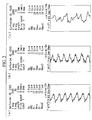
- Example 1 The conditions for shot peening in Example 1 and Example 2, the surface roughness values for the test specimens before and after shot peening, and the compressive residual stress, surface roughness and degree of deformation of the test specimens following shot peening are shown in Table 1. Furthermore, the surface profiles before and after shot peening in Example 1 are shown in FIG. 1(a) and FIG. 1(b) respectively, and the surface profiles before and after shot peening in Example 2 are shown in FIG. 2(a) and FIG. 2(b) respectively.
- Example 3 With the exception of replacing the test specimen with a sheet of a titanium alloy material (Ti-6Al-4V (an annealed material), dimensions: 19 mm x 76 mm x 2.4 mm), shot peening in Example 3 and Example 4 was performed in the same manner as in Example 1 and Example 2, respectively.
- Ti-6Al-4V an annealed material
- Example 3 Two titanium alloy materials having different surface roughness values were prepared as the pre-shot peening materials.
- Example 3 a titanium alloy material with a surface roughness of 1.64 ⁇ m prior to shot peening was used, whereas in Example 2, a titanium alloy material with a surface roughness of 3.2 ⁇ m prior to shot peening was used.
- Example 3 and Example 4 The conditions for shot peening in Example 3 and Example 4, the surface roughness values for the test specimens before and after shot peening, and the compressive residual stress, surface roughness, degree of deformation and fatigue life of the test specimens following shot peening are shown in Table 1.
- FIG. 3(a) and FIG. 3(b) the surface profiles before and after shot peening in Example 2 are shown in FIG. 4(a) and FIG. 4(b) respectively.
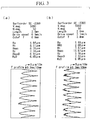
- the relationships between the average particle size (the media diameter) (most frequent particle size) of the shot material and the surface roughness when the surfaces of aluminum alloy materials (7050-T7451) having nominal surface roughness values of 8 microinches (0.2 ⁇ m), 63 microinches (1.6 ⁇ m) and 125 microinches (3.2 ⁇ m) were shot peened are shown in FIG. 5 .
- FIG. 5 it is clear that a linear relationship exists between the average particle size and the surface roughness, with the surface roughness increasing with increasing average particle size.
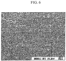
- FIG. 6 is an electron microscope photograph of the fatigue fracture surface of the specimen from Example 5. In the figure, the arrow indicates the fatigue fracture origin.
- FIG. 7 is an electron microscope photograph of the fatigue fracture surface of the specimen from Comparative Example 5. In the figure, the arrow indicates the fatigue fracture origin.
- Example 5 Comparison of Example 5 and Comparative Example 5 reveals that with microparticle shot peening, even though no corner chamfering had been performed, the edges did not act as fatigue fracture origins. Similar results were observed for aluminum alloy and steel test specimens. Based on these results, it can be stated that shot peening according to the present invention not only enables prevention of burrs caused by plastic deformation of edges, but also strengthens the entire surface including the edges, and improves the fatigue properties.
- shot peening according to the present invention produces a minimal degree of plastic deformation
- shot peening can also be performed on precision hole portions, which until now have been unable to be shot peened and have therefore required covering.
Description
- The present invention relates to a process for producing a metallic component having improved fatigue properties and a structural member.
- Shot peening represents a known example of a surface modification process that is used for enhancing the fatigue strength of metallic materials such as the structural members used in aircraft and automobiles and the like (see Non Patent Citation 1). Shot peening is a method in which, by blasting countless particles having a particle size of around 0.8 mm (the shot material) together with a stream of compressed air onto the surface of a metallic material, the hardness of the metallic material surface is increased, and a layer having compressive residual stress is formed at a certain depth.
- Furthermore, other techniques such as flapper peening and cold working are also used as methods of enhancing the fatigue strength of a metallic material.
- Non Patent Citation 1: T. Dorr and four others, "Influence of Shot Penning on Fatigue Performance of High-Strength Aluminum- and Magnesium Alloys", The 7th International Conference on Shot Peening, 1999, Institute of Precision Mechanics, Warsaw, Poland. Internet <URL: http://www.shotpeening.org/ICSP/icsp-7-20.pdf>
- However, shot peening increases the surface roughness of the member, meaning the prescribed surface roughness required for a particular application may not always be attainable. Furthermore, because of the increase in surface roughness and the effect of flaws generated on the surface of the member by the shot, a partial reduction in the degree of improvement in fatigue properties achieved by shot peening is unavoidable. A process that enables the fatigue properties of a member to be enhanced by shot peening while suppressing any increase in the surface roughness of the member or any flaw generation has yet to be discovered.
- On the other hand, flapper peening does not induce a high level of compressive residual stress, and as a result, satisfactory fatigue properties cannot be obtained. Furthermore, cold working processes require post-processing, meaning the process is more complex.
- Moreover, shot peening may also cause plastic deformation of the surface layer of the member, which can cause deformation problems such as bending. As a result, these types of problems have typically been prevented by using a tape or film-like pressure-sensitive adhesive mask to cover those areas of the material for which deformation such as bending or an increase in the surface roughness is likely to be problematic prior to shot peening. However, attaching and then removing a pressure-sensitive adhesive mask requires considerable effort, and results in extra costs.
- Moreover, when shot peening, if a shot particle strikes an edge of the member, then plastic deformation at the edge can cause a portion to fly off the member, generating a so-called burr. Because this type of burr can cause a deterioration in the fatigue properties of the member, the edges of metallic components must be chamfered or rounded prior to shot peening in order to prevent the generation of such burrs. However, chamfering or rounding of the edges is typically performed manually, meaning the efficiency is poor.
- The present invention has been developed in light of these circumstances, and has an object of providing a process for producing a metallic component of a structural member or the like used in an aircraft or automobile or the like, the process comprising shot peening the surface of a metallic material, wherein the fatigue properties of the metallic material can be improved with almost no variation in the surface roughness over the course of shot peening.
- Furthermore, the present invention also has an object of providing a process for producing a metallic component of a structural member or the like used in an aircraft or automobile or the like, the process comprising shot peening the surface of a metallic material, wherein by reducing deformation of the metallic material and suppressing increases in the surface roughness, covering of the metallic material surface becomes unnecessary, and the metallic component can be produced at a reduced cost.
- Moreover, the present invention also has an object of providing a process for producing a metallic component of a structural member or the like used in an aircraft or automobile or the like, the process comprising shot peening the surface of a metallic material, wherein chamfering or rounding of edges prior to shot peening is unnecessary, enabling reductions in the number of process steps and the production costs.
-
JP 2002-285237 A - Further shot peening processes are disclosed in
JP 2003-170353 A JP 2004-346424 A JP2005-248259 A JP 2005-264331 A - In order to achieve the objects described above, the present invention provides a process for producing a metallic component according to claim 1.
- According to this process, a metallic component having improved fatigue properties can be produced with small change in the surface roughness of the metallic material.
- In the following description, the surface roughness represented by the arithmetic mean roughness Ra is referred to as simply "the surface roughness". Furthermore, in the present invention, the "average particle size" is determined as the particle size corresponding with the peak in a frequency distribution curve, and is also referred to as the most frequent particle size or the modal diameter. Alternatively, the average particle size may also be determined using the methods listed below.
- (1) A method in which the average particle size is determined from a sieve curve (the particle size corresponding with R = 50% is deemed the median diameter or 50% particle size, and is represented using the symbol dp50).
- (2) A method in which the average particle size is determined from a Rosin-Rammler distribution.
- (3) Other methods (such as determining the number average particle size, length average particle size, area average particle size, volume average particle size, average surface area particle size, or average volume particle size).
- The surface roughness of the metallic material prior to the projection step is preferably not less than 0.7 µm and not more than 65 µm.
- If the surface roughness of the metallic material prior to the projection step is less than 0.7 µm, then the ratio of the surface roughness of the metallic material surface following the projection step relative to the surface roughness prior to the projection step tends to increase, and the effect of the present invention in improving the fatigue properties tends to diminish, which is undesirable.
- In order to ensure that the produced metallic component has satisfactory fatigue strength, the absolute value of the compressive residual stress at the metallic material surface following the projection step is preferably not less than 150 MPa.
- In the process for producing a metallic component according to the present invention, projection of the particles onto the surface of the metallic material may be performed without using the type of mask that is attached to the surface of a metallic material during conventional shot peening in order to prevent increases in the surface roughness or deformation of the metallic material.
- According to the process for producing a metallic component of the present invention, in addition to the fact that the surface roughness of the metallic material undergoes almost no change over the course of the projection step, almost no deformation such as bending occurs on the metallic material, meaning the type of pressure-sensitive adhesive mask used in conventional shot peening is unnecessary, and as a result, the steps of attaching and removing the pressure-sensitive adhesive mask are also unnecessary, enabling a dramatic reduction in the number of process steps and the production costs for the metallic components.
- Furthermore, in the process for producing a metallic component according to the present invention, neither chamfering nor rounding of the edges of the metallic material, which are conducted prior to the projection step in conventional shot peening in order to prevent the occurrence of burrs, need be performed.
- According to the process for producing a metallic component of the present invention, because no burrs are produced by plastic deformation even if a shot material particle strikes an edge of the metallic material, chamfering or rounding of the edges prior to the projection step is unnecessary. Accordingly, the number of process steps and the production costs for the metallic component can be reduced dramatically.
- Furthermore, a structural member of the present invention includes a metallic component produced using one of the production processes described above.
- This structural member has excellent fatigue properties, and has no deformation such as bending and no excessive surface roughness. Furthermore, because production can be performed without the need for covering with a pressure-sensitive adhesive mask and without chamfering or rounding of the edges, the structural member can be produced at a reduced cost. This structural member can be used favorably in the field of transportation machinery such as aircraft and automobiles, and in other fields that require favorable material fatigue properties.
- The present invention provides a process for producing a metallic component of a structural member or the like used in an aircraft or automobile or the like, the process comprising shot peening the surface of a metallic material, wherein the fatigue properties of the metallic material can be improved with almost no variation in the surface roughness over the course of shot peening.
- Furthermore, the present invention also provides a process for producing a metallic component of a structural member or the like used in an aircraft or automobile or the like, the process comprising shot peening the surface of a metallic material, wherein by reducing deformation of the metallic material and suppressing increases in the surface roughness, covering of the metallic material surface becomes unnecessary, and the metallic component can be produced at a reduced cost.
- Moreover, the present invention also provides a process for producing a metallic component of a structural member or the like used in an aircraft or automobile or the like, the process comprising shot peening the surface of a metallic material, wherein chamfering or rounding of edges prior to shot peening is unnecessary, enabling reductions in the number of process steps and the production costs.
-
- [
FIG. 1 ] A diagram showing the surface profiles of an aluminum alloy with a surface roughness of 1.2 µm before and after shot peening, wherein (a) represents the surface profile prior to shot peening, (b) represents the surface profile following shot peening in Example 1, and (c) represents the surface profile following shot peening in Comparative Example 3. - [
FIG. 2 ] A diagram showing the surface profiles of an aluminum alloy with a surface roughness of 2.9 µm before and after shot peening, wherein (a) represents the surface profile prior to shot peening, (b) represents the surface profile following shot peening in Example 2, and (c) represents the surface profile following shot peening in Comparative Example 4. - [
FIG. 3 ] A diagram showing the surface profiles of a titanium alloy with a surface roughness of 1.64 µm before and after shot peening, wherein (a) represents the surface profile prior to shot peening, and (b) represents the surface profile following shot peening in Example 3. - [
FIG. 4 ] A diagram showing the surface profiles of a titanium alloy with a surface roughness of 3.2 µm before and after shot peening, wherein (a) represents the surface profile prior to shot peening, and (b) represents the surface profile following shot peening in Example 4. - [
FIG. 5 ] A graph showing the relationship between the average particle size of the shot material and the surface roughness. - [
FIG. 6 ] An electron microscope photograph of the fatigue fracture surface of a specimen from Example 5. - [
FIG. 7 ] An electron microscope photograph of the fatigue fracture surface of a specimen from Comparative Example 5. - A description of embodiments of the process for producing a metallic component according to the present invention is presented below, with reference to the drawings.
- In the process for producing a metallic component according to the present invention, a lightweight alloy material or steel material is used. Examples of the lightweight alloy include aluminum alloys and titanium alloys.
- In the process for producing a metallic component according to the present invention, the particles (the shot material) used in shot peening the metallic material are hard particles of a metal, ceramic or glass or the like, and are preferably ceramic particles such as alumina or silica particles.
- In conventional shot peening, a shot material with a particle size of around 0.8 mm is used, but in the present invention, a shot material with an average particle size of not more than 200 µm is used. The average particle size of the shot material is preferably not less than 10 µm and not more than 200 µm, and is even more preferably not less than 30 µm and not more than 100 µm. If the average particle size of the shot material particles is greater than 200 µm, then the excessively large kinetic energy of the particles causes damage to the material surface, meaning a satisfactory improvement in the fatigue life cannot be achieved. Furthermore, if the average particle size of the shot material particles is smaller than 10 µm, then blockages and the like of the shot material mean achieving a stable spray state is very difficult.
- The shot velocity of the shot material is regulated by the air pressure of the compressed air stream. When shot peening according to the present invention, the air pressure is preferably not less than 0.1 MPa and not more than 1 MPa, and is even more preferably not less than 0.3 MPa and not more than 0.6 MPa. If the air pressure is greater than 1 MPa, then the excessively large kinetic energy of the particles causes damage to the material surface, meaning a satisfactory improvement in the fatigue life cannot be achieved. Furthermore, if the air pressure is less than 0.1 MPa, then achieving a stable spray state becomes very difficult.
- The shot material particles are preferably spherical in shape. The reason for this preference is that if the shot material particles are sharp, then the surface of the metallic component may become damaged.
- The coverage by shot peening is preferably not less than 100% and not more than 1,000%, and is even more preferably not less than 100% and not more than 500%. At coverage levels of 100% or lower, a satisfactory improvement in the fatigue strength cannot be obtained. Furthermore, coverage levels of 1,000% or higher are also undesirable, as the increase in temperature at the material surface causes a reduction in the compressive residual stress at the outermost surface, and a satisfactory improvement in fatigue strength cannot be obtained.
- A metallic component that has been shot peened under the conditions described above preferably exhibits the surface properties (surface compressive residual stress and surface roughness) described below.
- In a metallic component that has been shot peened in accordance with the present invention, a high compressive residual stress of not less than 150 MPa exists either at the outermost surface of the material, or within the vicinity thereof. As a result, the surface is strengthened and fatigue failure occurs not at the surface, but within the interior of the material, meaning the fatigue life increases significantly.
- The treatment by shot peening in the present invention is performed so that there is almost no change in the surface roughness over the course of the treatment. The ratio of the surface roughness following shot peening relative to the surface roughness prior to shot peening is preferably not less than 0.8 and not more than 1.5. If this surface roughness ratio exceeds 1.5, then the surface of the metallic component following shot peening tends to be rough, which results in surface damage and can cause an undesirable reduction in the fatigue life.
- By shot peening the metallic material under the above conditions, a surface-treated metallic component of the present invention is obtained.
- A more detailed description of the process for producing a metallic component according to the present invention is presented below using a series of examples and comparative examples.
- A sheet of an aluminum alloy material (7050-T7451, dimensions: 19 mm x 76 mm x 2.4 mm) was used as a test specimen. One surface of this specimen was shot peened using a shot material composed of alumina/silica ceramic particles with an average particle size (most frequent particle size) of not more than 50 µm, under conditions including an air pressure of 0.4 MPa and a spray time of 30 seconds.
- Two aluminum alloy materials having different surface roughness values were prepared as the pre-shot peening materials. In Example 1, an aluminum alloy material with a surface roughness of 1.2 µm prior to shot peening was used, whereas in Example 2, an aluminum alloy material with a surface roughness of 2.9 µm prior to shot peening was used.
- A dynamic microparticle shot apparatus (model number: P-SGF-4ATCM-401, manufactured by Fuji Manufacturing Co., Ltd.) was used as the shot peening apparatus.
- Following shot peening, the surface roughness, compressive residual stress, and degree of deformation of the test specimens were measured.
- The conditions for shot peening in Example 1 and Example 2, the surface roughness values for the test specimens before and after shot peening, and the compressive residual stress, surface roughness and degree of deformation of the test specimens following shot peening are shown in Table 1. Furthermore, the surface profiles before and after shot peening in Example 1 are shown in
FIG. 1(a) and FIG. 1(b) respectively, and the surface profiles before and after shot peening in Example 2 are shown inFIG. 2(a) and FIG. 2(b) respectively. - With the exception of replacing the shot material with conventional zirconia particles having an average particle size (most frequent particle size) of 250 µm, shot peening in Comparative Example 1 and Comparative Example 2 was performed in the same manner as in Example 1 and Example 2, respectively.
- The conditions for shot peening of Comparative Example 1 and Comparative Example 2, the surface roughness values for the test specimens before and after shot peening, and the compressive residual stress, surface roughness, degree of deformation and fatigue life of the test specimens following shot peening are shown in Table 1.
- With the exception of replacing the shot material with conventional cast steel particles having an average particle size (most frequent particle size) of 500 to 800 µm, shot peening in Comparative Example 3 and Comparative Example 4 was performed in the same manner as in Example 1 and Example 2, respectively.
- The conditions for shot peening in Comparative Example 3 and Comparative Example 4, the surface roughness values for the test specimens before and after shot peening, and the compressive residual stress, surface roughness, degree of deformation and fatigue life of the test specimens following shot peening are shown in Table 1. Furthermore, the surface profile before and after shot peening in Comparative Example 3 is shown in
FIG. 1(c) , and the surface profile before and after shot peening in Comparative Example 4 is shown inFIG. 2(c) . - With the exception of replacing the test specimen with a sheet of a titanium alloy material (Ti-6Al-4V (an annealed material), dimensions: 19 mm x 76 mm x 2.4 mm), shot peening in Example 3 and Example 4 was performed in the same manner as in Example 1 and Example 2, respectively.
- Two titanium alloy materials having different surface roughness values were prepared as the pre-shot peening materials. In Example 3, a titanium alloy material with a surface roughness of 1.64 µm prior to shot peening was used, whereas in Example 2, a titanium alloy material with a surface roughness of 3.2 µm prior to shot peening was used.
- The conditions for shot peening in Example 3 and Example 4, the surface roughness values for the test specimens before and after shot peening, and the compressive residual stress, surface roughness, degree of deformation and fatigue life of the test specimens following shot peening are shown in Table 1. The fatigue life was evaluated by performing a tension-tension fatigue test (stress ratio R = 0.1, maximum stress: 345 MPa) on a round bar-shaped smooth test specimen having a length of 135 mm and a gauge diameter of 6.35 mm. Furthermore, the surface profiles before and after shot peening in Example 3 are shown in
FIG. 3(a) and FIG. 3(b) respectively, and the surface profiles before and after shot peening in Example 2 are shown inFIG. 4(a) and FIG. 4(b) respectively.
- From the results shown in Table 1 and
FIG. 1 to FIG. 4 it is evident that compared with treatments by shot peening in Comparative Example 1 to Comparative Example 4 that used conventional shot materials, treatments by shot peening in Example 1 to Example 4 that used a microparticle shot material yielded a smaller variation in the surface roughness over the course of shot peening. It is thought that, as a result, shot peening in Example 1 to Example 4 results in less damage to the surface of the material. Furthermore, in shot peening in Example 1 and Example 2, a larger compressive residual stress was confirmed in the material following shot peening than that observed following shot peening in Comparative Example 1 to Comparative Example 4. Accordingly, shot peening in Example 1 to Example 4 enables alloy members having excellent fatigue properties to be obtained. - Furthermore, compared with the treatments by shot peening in Comparative Example 3 and Comparative Example 4, treatments by shot peening in Example 1 to Example 4 result in a smaller degree of deformation of the test specimen. Accordingly, shot peening in Example 1 to Example 4 removes the necessity for covering those regions for which increases in bending or surface roughness would prove problematic, meaning the steps of attaching and removing a mask are also unnecessary, and as a result, extra costs are not incurred in shot peening.
- The relationships between the average particle size (the media diameter) (most frequent particle size) of the shot material and the surface roughness when the surfaces of aluminum alloy materials (7050-T7451) having nominal surface roughness values of 8 microinches (0.2 µm), 63 microinches (1.6 µm) and 125 microinches (3.2 µm) were shot peened are shown in
FIG. 5 . As shown inFIG. 5 , it is clear that a linear relationship exists between the average particle size and the surface roughness, with the surface roughness increasing with increasing average particle size. Furthermore a trend is observed wherein smaller initial surface roughness values yield a greater variation in surface roughness upon changes in the average particle size, and when the average particle size approaches the average particle size (around 0.8 mm) of the shot materials used in typical treatments by shot peening, the effect of the initial surface roughness is almost non-existent, with the surface roughness following shot peening being substantially equal for all of the specified aluminum alloy materials. - The area around the hole within a test specimen composed of a flat sheet of a titanium alloy (Ti-6Al-4V (an annealed material)) with a hole formed therein was shot peened in the same manner as Example 3. No processing such as chamfering or rounding of the hole edges was performed prior to shot peening. Following a fatigue test, the fatigue fracture surface was inspected using an electron microscope.
FIG. 6 is an electron microscope photograph of the fatigue fracture surface of the specimen from Example 5. In the figure, the arrow indicates the fatigue fracture origin. - From the electron microscope photograph of
FIG. 6 it is evident that the fatigue fracture origin is several tens of µm inside the inner surface of the hole within the specimen of Example 5. - The results of performing a fatigue test (a tension-tension fatigue test, stress ratio R = 0.1) using the above hole-containing flat sheet are shown in Table 2. It is clear that despite the fact that no processing such as chamfering or rounding of the hole edges was performed, using a microparticle shot enabled a dramatic improvement in the fatigue life beyond the result achievable using a typical shot material on a test specimen that had been subjected to processing such as chamfering or rounding of the hole edges (see Comparative Example 5 below).
[Table 2] Material / Test stress (MPa) Reamed hole Typical shot treatment Microparticle shot treatment Fatigue life improvement (microparticle shot / reaming) SNCM439 tempered steel / 620 83,703 79,194 10,100,748 (no fracture) 120-fold or more Ti-6Al-4V annealed material / 540 38,516 58,850 464,451 12-fold A7075-T73/200 81,001 88,489 1,005,819 12-fold - The edges of the hole in a test specimen composed of a hole-containing sheet of a titanium alloy (Ti-6Al-4V (an annealed material)) were chamfered, and the area around the hole was then shot peened in the same manner as Comparative Example 3 and Comparative Example 4. Following a fatigue test, the fatigue fracture surface was inspected using an electron microscope.
FIG. 7 is an electron microscope photograph of the fatigue fracture surface of the specimen from Comparative Example 5. In the figure, the arrow indicates the fatigue fracture origin. - From the electron microscope photograph of
FIG. 7 it is evident that the fatigue fracture origin occurs at the chamfered portion of the hole edge in Comparative Example 5. - Comparison of Example 5 and Comparative Example 5 reveals that with microparticle shot peening, even though no corner chamfering had been performed, the edges did not act as fatigue fracture origins. Similar results were observed for aluminum alloy and steel test specimens. Based on these results, it can be stated that shot peening according to the present invention not only enables prevention of burrs caused by plastic deformation of edges, but also strengthens the entire surface including the edges, and improves the fatigue properties.
- Furthermore, by taking advantage of the fact that shot peening according to the present invention produces a minimal degree of plastic deformation, shot peening can also be performed on precision hole portions, which until now have been unable to be shot peened and have therefore required covering.
Claims (8)
- A process for producing a metallic component, comprising a projection step of projecting particles together with a stream of compressed air onto a surface of a metallic material comprising a lightweight alloy or a steel, wherein
an average particle size of the particles is not more than 200 µm,
an air pressure of the compressed air stream is not less than 0.1 MPa and not more than 1 MPa, and
a ratio of an arithmetic mean roughness of the surface of the metallic material following the projection step relative to the arithmetic mean roughness of the surface of the metallic material prior to the projection step is not less than 0.8 and not more than 1.5. - The process for producing a metallic component according to claim 1, wherein an arithmetic surface roughness of the surface of the metallic material prior to the projection step is not less than 0.7 m and not more than 65 µm.
- The process for producing a metallic component according to either claim 1 or 2, wherein an absolute value of a compressive residual stress at the surface of the metallic material following the projection step is not less than 150 MPa.
- The process for producing a metallic component according to any one of claims 1 to 3, wherein projection of the particles onto the surface of the metallic material is performed without using a mask to cover the surface of the metallic material.
- The process for producing a metallic component according to any one of claims 1 to 4, wherein neither chamfering nor rounding of edges of the metallic material is performed prior to the projection step.
- The process for producing a metallic component according to any one of claims 1 to 5, wherein the air pressure of the compressed air stream is not less than 0.3 MPa and not more than 0.6 MPa.
- The process for producing a metallic component according to any one of claims 1 to 6, wherein the average particle size of the particles is not less than 30 µm and not more than 100 µm.
- A structural member having a metallic component produced using the process according to any one of claims 1 to 7.
Applications Claiming Priority (2)
| Application Number | Priority Date | Filing Date | Title |
|---|---|---|---|
| JP2006070794A JP5039311B2 (en) | 2006-03-15 | 2006-03-15 | Metal member manufacturing method and structural member |
| PCT/JP2007/055141 WO2007105775A1 (en) | 2006-03-15 | 2007-03-14 | Process for manufacturing metal member, and structural member |
Publications (3)
| Publication Number | Publication Date |
|---|---|
| EP1995335A1 EP1995335A1 (en) | 2008-11-26 |
| EP1995335A4 EP1995335A4 (en) | 2010-11-03 |
| EP1995335B1 true EP1995335B1 (en) | 2016-05-18 |
Family
ID=38509591
Family Applications (1)
| Application Number | Title | Priority Date | Filing Date |
|---|---|---|---|
| EP07738611.8A Expired - Fee Related EP1995335B1 (en) | 2006-03-15 | 2007-03-14 | Process for manufacturing metal member, and structural member |
Country Status (8)
| Country | Link |
|---|---|
| US (1) | US7934407B2 (en) |
| EP (1) | EP1995335B1 (en) |
| JP (1) | JP5039311B2 (en) |
| CN (1) | CN101400808A (en) |
| BR (1) | BRPI0708890B1 (en) |
| CA (1) | CA2645470C (en) |
| RU (1) | RU2413776C2 (en) |
| WO (1) | WO2007105775A1 (en) |
Families Citing this family (4)
| Publication number | Priority date | Publication date | Assignee | Title |
|---|---|---|---|---|
| JP5086756B2 (en) * | 2007-10-05 | 2012-11-28 | 三菱重工業株式会社 | Repair method for metal parts |
| JP2009291889A (en) * | 2008-06-05 | 2009-12-17 | Mitsubishi Heavy Ind Ltd | Metal member method for manufacturing, and metal member |
| RU2570716C2 (en) * | 2014-04-08 | 2015-12-10 | Федеральное государственное бюджетное образовательное учреждение высшего профессионального образования Балтийский государственный технический университет "ВОЕНМЕХ" им. Д.Ф. Устинова (БГТУ "ВОЕНМЕХ") | Thermal processing of structural steels to high-strength state |
| CN117464327B (en) * | 2023-12-25 | 2024-03-19 | 中北大学 | Method for prolonging fatigue life of hydrogen delivery pipe of 6061 aluminum alloy hydrogenation gun |
Family Cites Families (12)
| Publication number | Priority date | Publication date | Assignee | Title |
|---|---|---|---|---|
| US3073022A (en) * | 1959-04-03 | 1963-01-15 | Gen Motors Corp | Shot-peening treatments |
| US4914796A (en) * | 1988-12-12 | 1990-04-10 | Eastman Kodak Company | Process for manufacturing nickel coated shot blasted web conveying roller |
| US5598730A (en) * | 1994-08-30 | 1997-02-04 | Snap-On Technologies, Inc. | Pre-forge aluminum oxide blasting of forging billets as a scale resistance treatment |
| JP2000141225A (en) * | 1998-11-09 | 2000-05-23 | Canon Inc | Working method for surface of work piece |
| JP3651665B2 (en) * | 2001-03-27 | 2005-05-25 | Jfeスチール株式会社 | Cold-rolled steel sheet with excellent press formability and sharpness after painting |
| JP2002301663A (en) | 2001-04-04 | 2002-10-15 | Isuzu Motors Ltd | Fatigue strength improvement method for aluminum casting |
| JP2003170353A (en) * | 2001-12-06 | 2003-06-17 | Sintokogio Ltd | Manufacturing method of valve spring and valve spring |
| JP4674843B2 (en) * | 2003-04-28 | 2011-04-20 | 新東工業株式会社 | Coil spring manufacturing method |
| JP2005186241A (en) * | 2003-12-26 | 2005-07-14 | Furukawa Electric Co Ltd:The | Manufacturing method for aluminum-alloy blank material for magnetic disc |
| JP4507640B2 (en) * | 2004-03-04 | 2010-07-21 | Jfeスチール株式会社 | Manufacturing method of high strength steel sheet |
| JP2005264331A (en) * | 2005-03-11 | 2005-09-29 | Yanmar Co Ltd | Machine structural components |
| JP4699264B2 (en) * | 2006-04-03 | 2011-06-08 | 三菱重工業株式会社 | Metal member manufacturing method and structural member |
-
2006
- 2006-03-15 JP JP2006070794A patent/JP5039311B2/en active Active
-
2007
- 2007-03-14 BR BRPI0708890-6A patent/BRPI0708890B1/en not_active IP Right Cessation
- 2007-03-14 CN CN200780008830.7A patent/CN101400808A/en active Pending
- 2007-03-14 CA CA2645470A patent/CA2645470C/en not_active Expired - Fee Related
- 2007-03-14 EP EP07738611.8A patent/EP1995335B1/en not_active Expired - Fee Related
- 2007-03-14 US US12/224,959 patent/US7934407B2/en not_active Expired - Fee Related
- 2007-03-14 RU RU2008137101/02A patent/RU2413776C2/en active
- 2007-03-14 WO PCT/JP2007/055141 patent/WO2007105775A1/en active Application Filing
Also Published As
| Publication number | Publication date |
|---|---|
| RU2413776C2 (en) | 2011-03-10 |
| CA2645470A1 (en) | 2007-09-20 |
| RU2008137101A (en) | 2010-04-20 |
| JP5039311B2 (en) | 2012-10-03 |
| BRPI0708890B1 (en) | 2018-05-15 |
| CA2645470C (en) | 2013-03-05 |
| BRPI0708890A2 (en) | 2011-06-28 |
| EP1995335A1 (en) | 2008-11-26 |
| US20090023014A1 (en) | 2009-01-22 |
| EP1995335A4 (en) | 2010-11-03 |
| WO2007105775A1 (en) | 2007-09-20 |
| US7934407B2 (en) | 2011-05-03 |
| JP2007245275A (en) | 2007-09-27 |
| CN101400808A (en) | 2009-04-01 |
Similar Documents
| Publication | Publication Date | Title |
|---|---|---|
| EP2008771B1 (en) | Process for producing metallic member | |
| US8024846B2 (en) | Preparation of an article surface having a surface compressive texture | |
| EP2353782B1 (en) | Peening process for enhancing surface finish of a component | |
| EP1995335B1 (en) | Process for manufacturing metal member, and structural member | |
| EP2202331B1 (en) | Process for producing metal member, structure member with thus produced metal member, and method of repairing metal member | |
| CA2592523C (en) | Surface-treated light alloy member and method for manufacturing same | |
| EP3460090A1 (en) | Surface treatment method for metal product and metal product | |
| JP2016182657A (en) | Suspension arm made of aluminum alloy, and manufacturing method thereof | |
| EP2186601A1 (en) | Metal member manufacturing method and metal member | |
| JP3651665B2 (en) | Cold-rolled steel sheet with excellent press formability and sharpness after painting | |
| JP2007245248A (en) | Method for manufacturing light metal panel component, and light metal panel component | |
| WO2022138837A1 (en) | Titanium material | |
| JPS6284974A (en) | Method of highly strengthening outer surface of metal | |
| JP6125780B2 (en) | Surface modification method by shot peening | |
| JP2004009197A (en) | Strengthening method for welded part made of light metal and welded part made of light metal |
Legal Events
| Date | Code | Title | Description |
|---|---|---|---|
| PUAI | Public reference made under article 153(3) epc to a published international application that has entered the european phase |
Free format text: ORIGINAL CODE: 0009012 |
|
| 17P | Request for examination filed |
Effective date: 20080910 |
|
| AK | Designated contracting states |
Kind code of ref document: A1 Designated state(s): DE FR GB |
|
| RBV | Designated contracting states (corrected) |
Designated state(s): DE FR GB |
|
| A4 | Supplementary search report drawn up and despatched |
Effective date: 20101004 |
|
| RIC1 | Information provided on ipc code assigned before grant |
Ipc: C21D 7/06 20060101AFI20071005BHEP Ipc: B21D 22/02 20060101ALI20100928BHEP Ipc: B24C 1/10 20060101ALI20100928BHEP |
|
| DAX | Request for extension of the european patent (deleted) | ||
| RIC1 | Information provided on ipc code assigned before grant |
Ipc: B21D 22/02 20060101ALI20151218BHEP Ipc: C21D 7/06 20060101AFI20151218BHEP Ipc: B24C 1/10 20060101ALI20151218BHEP |
|
| GRAP | Despatch of communication of intention to grant a patent |
Free format text: ORIGINAL CODE: EPIDOSNIGR1 |
|
| INTG | Intention to grant announced |
Effective date: 20160212 |
|
| GRAS | Grant fee paid |
Free format text: ORIGINAL CODE: EPIDOSNIGR3 |
|
| GRAA | (expected) grant |
Free format text: ORIGINAL CODE: 0009210 |
|
| AK | Designated contracting states |
Kind code of ref document: B1 Designated state(s): DE FR GB |
|
| REG | Reference to a national code |
Ref country code: GB Ref legal event code: FG4D |
|
| REG | Reference to a national code |
Ref country code: DE Ref legal event code: R096 Ref document number: 602007046357 Country of ref document: DE |
|
| REG | Reference to a national code |
Ref country code: FR Ref legal event code: PLFP Year of fee payment: 11 |
|
| REG | Reference to a national code |
Ref country code: DE Ref legal event code: R097 Ref document number: 602007046357 Country of ref document: DE |
|
| PLBE | No opposition filed within time limit |
Free format text: ORIGINAL CODE: 0009261 |
|
| STAA | Information on the status of an ep patent application or granted ep patent |
Free format text: STATUS: NO OPPOSITION FILED WITHIN TIME LIMIT |
|
| 26N | No opposition filed |
Effective date: 20170221 |
|
| REG | Reference to a national code |
Ref country code: FR Ref legal event code: PLFP Year of fee payment: 12 |
|
| PGFP | Annual fee paid to national office [announced via postgrant information from national office to epo] |
Ref country code: DE Payment date: 20200303 Year of fee payment: 14 Ref country code: GB Payment date: 20200304 Year of fee payment: 14 |
|
| PGFP | Annual fee paid to national office [announced via postgrant information from national office to epo] |
Ref country code: FR Payment date: 20210210 Year of fee payment: 15 |
|
| REG | Reference to a national code |
Ref country code: DE Ref legal event code: R119 Ref document number: 602007046357 Country of ref document: DE |
|
| GBPC | Gb: european patent ceased through non-payment of renewal fee |
Effective date: 20210314 |
|
| PG25 | Lapsed in a contracting state [announced via postgrant information from national office to epo] |
Ref country code: GB Free format text: LAPSE BECAUSE OF NON-PAYMENT OF DUE FEES Effective date: 20210314 Ref country code: DE Free format text: LAPSE BECAUSE OF NON-PAYMENT OF DUE FEES Effective date: 20211001 |
|
| PG25 | Lapsed in a contracting state [announced via postgrant information from national office to epo] |
Ref country code: FR Free format text: LAPSE BECAUSE OF NON-PAYMENT OF DUE FEES Effective date: 20220331 |