EP1995047A1 - Verfahren zur Herstellung eines Fahrzeugluftreifens und Fahrzeugluftreifen - Google Patents
Verfahren zur Herstellung eines Fahrzeugluftreifens und Fahrzeugluftreifen Download PDFInfo
- Publication number
- EP1995047A1 EP1995047A1 EP08152576A EP08152576A EP1995047A1 EP 1995047 A1 EP1995047 A1 EP 1995047A1 EP 08152576 A EP08152576 A EP 08152576A EP 08152576 A EP08152576 A EP 08152576A EP 1995047 A1 EP1995047 A1 EP 1995047A1
- Authority
- EP
- European Patent Office
- Prior art keywords
- strips
- short fibers
- mixture
- fibers
- tread
- Prior art date
- Legal status (The legal status is an assumption and is not a legal conclusion. Google has not performed a legal analysis and makes no representation as to the accuracy of the status listed.)
- Granted
Links
Images
Classifications
-
- B—PERFORMING OPERATIONS; TRANSPORTING
- B29—WORKING OF PLASTICS; WORKING OF SUBSTANCES IN A PLASTIC STATE IN GENERAL
- B29D—PRODUCING PARTICULAR ARTICLES FROM PLASTICS OR FROM SUBSTANCES IN A PLASTIC STATE
- B29D30/00—Producing pneumatic or solid tyres or parts thereof
- B29D30/06—Pneumatic tyres or parts thereof (e.g. produced by casting, moulding, compression moulding, injection moulding, centrifugal casting)
- B29D30/08—Building tyres
- B29D30/10—Building tyres on round cores, i.e. the shape of the core is approximately identical with the shape of the completed tyre
- B29D30/16—Applying the layers; Guiding or stretching the layers during application
- B29D30/1621—Applying the layers; Guiding or stretching the layers during application by feeding a continuous band and winding it spirally, i.e. the band is fed without relative movement along the core axis, to form an annular element
-
- B—PERFORMING OPERATIONS; TRANSPORTING
- B29—WORKING OF PLASTICS; WORKING OF SUBSTANCES IN A PLASTIC STATE IN GENERAL
- B29D—PRODUCING PARTICULAR ARTICLES FROM PLASTICS OR FROM SUBSTANCES IN A PLASTIC STATE
- B29D30/00—Producing pneumatic or solid tyres or parts thereof
- B29D30/06—Pneumatic tyres or parts thereof (e.g. produced by casting, moulding, compression moulding, injection moulding, centrifugal casting)
- B29D30/08—Building tyres
- B29D30/20—Building tyres by the flat-tyre method, i.e. building on cylindrical drums
- B29D30/30—Applying the layers; Guiding or stretching the layers during application
- B29D30/3021—Applying the layers; Guiding or stretching the layers during application by feeding a continuous band and winding it spirally, i.e. the band is fed without relative movement along the drum axis, to form an annular element
-
- B—PERFORMING OPERATIONS; TRANSPORTING
- B29—WORKING OF PLASTICS; WORKING OF SUBSTANCES IN A PLASTIC STATE IN GENERAL
- B29D—PRODUCING PARTICULAR ARTICLES FROM PLASTICS OR FROM SUBSTANCES IN A PLASTIC STATE
- B29D30/00—Producing pneumatic or solid tyres or parts thereof
- B29D30/06—Pneumatic tyres or parts thereof (e.g. produced by casting, moulding, compression moulding, injection moulding, centrifugal casting)
- B29D30/52—Unvulcanised treads, e.g. on used tyres; Retreading
- B29D30/58—Applying bands of rubber treads, i.e. applying camel backs
- B29D30/60—Applying bands of rubber treads, i.e. applying camel backs by winding narrow strips
-
- B—PERFORMING OPERATIONS; TRANSPORTING
- B60—VEHICLES IN GENERAL
- B60C—VEHICLE TYRES; TYRE INFLATION; TYRE CHANGING; CONNECTING VALVES TO INFLATABLE ELASTIC BODIES IN GENERAL; DEVICES OR ARRANGEMENTS RELATED TO TYRES
- B60C11/00—Tyre tread bands; Tread patterns; Anti-skid inserts
- B60C11/0041—Tyre tread bands; Tread patterns; Anti-skid inserts comprising different tread rubber layers
- B60C11/005—Tyre tread bands; Tread patterns; Anti-skid inserts comprising different tread rubber layers with cap and base layers
-
- B—PERFORMING OPERATIONS; TRANSPORTING
- B60—VEHICLES IN GENERAL
- B60C—VEHICLE TYRES; TYRE INFLATION; TYRE CHANGING; CONNECTING VALVES TO INFLATABLE ELASTIC BODIES IN GENERAL; DEVICES OR ARRANGEMENTS RELATED TO TYRES
- B60C11/00—Tyre tread bands; Tread patterns; Anti-skid inserts
- B60C11/14—Anti-skid inserts, e.g. vulcanised into the tread band
-
- B—PERFORMING OPERATIONS; TRANSPORTING
- B60—VEHICLES IN GENERAL
- B60C—VEHICLE TYRES; TYRE INFLATION; TYRE CHANGING; CONNECTING VALVES TO INFLATABLE ELASTIC BODIES IN GENERAL; DEVICES OR ARRANGEMENTS RELATED TO TYRES
- B60C19/00—Tyre parts or constructions not otherwise provided for
- B60C19/08—Electric-charge-dissipating arrangements
Definitions
- the invention relates to a method for producing a pneumatic vehicle tire having a tread cap and a tread base tread, a carcass ply and a belt bandage, wherein at least the tread cap is constructed on a building drum by winding at least one extruded rubber compound strip
- the tread cap of a tread of a pneumatic vehicle tire by overlapping helical winding (coils) of preferably extruded rubber compound strips.
- the EP-B-1072 446 a tire having a tread with radially oriented staple fibers composed of a non-metallic inorganic material, wherein a mixture web having longitudinally oriented fibers is formed by calendering the rubber blend blended with the staple fibers. This mixture web is then folded several times, so that from the folded web a tread can be created in which a majority of the fibers is oriented in the radial direction. Treads with fibers oriented in the radial direction have increased static friction to the ground, in particular, such treads can ensure a significantly improved grip on snowy or icy ground.
- the invention is based on the object to be able to make the coils of tread parts with mixing strips variable and efficient than before.
- the object is achieved according to the invention in that the mixture strip is divided longitudinally into two mixing strips, which are applied synchronously at a position or at different positions of the building drum by means of coils.
- the invention therefore makes it possible, as it were to double a mixing strip produced by extrusion, so that the usual cycle times of winding can be significantly reduced.
- the short fibers are applied or attached with a preferred orientation. In this way, specific properties of the tread can be specifically influenced. In principle, it is also possible to pin the short fibers disorderly.
- the short fibers can be applied in an automatically running operation on the one or more mixing strips. Such a possibility exists, for example, when the short fibers are dispensed from a dispenser cassette or the like.
- the invention is particularly advantageous because before the coils of the two mixture strips on at least one of the wide sides sections or in places an electrically conductive rubber mixture in the form of strips, short webs and the like can be applied.
- short fibers are especially well suited, which have a length of 0.1 mm to 5 mm and a diameter of 1 .mu.m to 100 .mu.m.
- the short fibers can be used as staple fibers or as individual fibers and consist of different materials, in particular of organic and / or inorganic materials.
- the invention further relates to a pneumatic vehicle tire, which is produced by the method according to the invention.
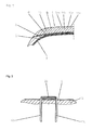
- Fig. 1 schematically shows a partial section through the tread area of a still unvulcanized pneumatic vehicle tire for cars.
- the tire comprises an inner layer 1, a radial carcass 2, a belt bandage 3, which in the illustrated embodiment consists of two belt plies, and a tread 4, which consists of a tread base 6 directly on the belt bandage 3 and a tread cap 5, which consists of different Rubber mixtures are made.
- a tread cap 5 in the vulcanization of the green tire in a vulcanization mold a profiling of grooves, grooves, cuts and the like is impressed.
- the tread cap 5 is constructed of alternately adjacent mixture strips 10a, 10b.
- the tread base 6 can also be made of a rubber mix strip or as a monopart.
- the rubber mixture strips 10a, 10b each have a width of preferably 10 mm to 20 mm and a thickness of in particular up to 2 mm and are applied by spiral winding (winding) on a building drum or auxiliary drum 12.
- auxiliary drum 12 is segmented in a known, not shown manner and is set in the coil of the mixture strips 10a, 10b in rotation.
- the segments of the auxiliary drum 12 are extended and retracted so that the outer diameter of the auxiliary drum 12 can be increased and decreased.
- a mixture strip 10 is extruded which has a width which corresponds to twice the width of the mixing strips 10a, 10b.
- the wide blend strip 10 is split longitudinally (cut) centrally into two matching blend strips 10a, 10b, whereby the strips 10a, 10b are only half as thick as the strip 10.
- the blend strips 10a, 10b are spread apart via deflection rollers 19a or the like and then joined together again by means of further deflection rollers 19b.
- short fibers 14 for example oriented transversely to the longitudinal extension of the strips 10a, 10b, are applied at least to the broad inner side of one of the two mixing strips 10a, 10b.
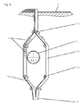
- the short fibers 14 are of a in Fig. 2 indicated dispenser cassette 15 is dispensed, which adheres the short fibers 14 aligned on the mixing strip 10a.
- the inherent tackiness of the mix strip 10a supports the adhesion of the short fibers 14.
- the mixture strip 10a may be coated with a adhesion-enhancing substance prior to application of the short fibers 14.
- the reassembled strips 10a, 10b are then wound together on the already applied to the auxiliary drum 12 tread base 6.
- Correspondingly oriented or unoriented short fibers 14 are located in the finished rolled-up tread cap along circumferential webs.
- the blend strips 10a, 10b formed from a wide extruded blend strip are not reassembled, but remain separate from each other and are individually but synchronously spooled to build one tread half, for example.
- short fibers can be applied at least on one side.
- Fig. 3 further comprises a circumferentially rotating compound strand 20 positioned on the tread base 6, which is made of an electrically conductive rubber compound and is intended for the case where the blend strips 10a, 10b are made of a rubber compound containing silica as filler and no or no contains significant amount of carbon black and thus is electrically non-conductive.
- the strand 20 provides a circumferentially encircling electrically conductive passage between the tread base 6 and the outside of the tread cap 5 so that electrostatic charging of the tire is avoided.
- the short fibers 14 used can be in the form of fiber bundles or as individual fibers. Their diameter is between 1 ⁇ m to 100 ⁇ m, their average length is between 0.1 mm and 5 mm.
- As the material for the short fibers 14 are mainly organic and / or inorganic materials in question, for example, aramids, polyesters, rayon, and hybrid materials of these materials, also carbon fibers or glass fibers.
- the fibers can be applied to the mixture strips in a variety of ways. For example, it is possible to inflate the fibers.
- the fibers may also be cut off from a fiber strand just prior to tacking.
- the fibers may also already be positioned on a thin film so that the film is relined onto the compound strip.
Landscapes
- Engineering & Computer Science (AREA)
- Mechanical Engineering (AREA)
- Tyre Moulding (AREA)
- Tires In General (AREA)
Abstract
Description
- Die Erfindung betrifft ein Verfahren zur Herstellung eines Fahrzeugluftreifens mit einem Laufstreifen aus einer Laufstreifencap und einer Laufstreifenbase, einer Karkasseinlage und einem Gürtelverband, wobei zumindest die Laufstreifencap auf einer Aufbautrommel durch Spulen von zumindest einem extrudierten Kautschukmischungsstreifen aufgebaut wird
- Es ist bekannt, die Laufstreifencap eines Laufstreifens eines Fahrzeugluftreifens durch überlappendes spiraliges Wickeln (Spulen) von vorzugsweise extrudierten Kautschukmischungsstreifen herzustellen. Des Weiteren offenbart die
EP-B-1072 446 einen Reifen mit einem Laufstreifen mit in radialer Richtung orientierten Stapelfasern, welche aus einem nicht-metallischen anorganischen Material bestehen, wobei aus der mit den Stapelfasern vermischten Kautschukmischung durch Kalandrieren eine Mischungsbahn mit in Längsrichtung orientierten Fasern erstellt wird. Diese Mischungsbahn wird anschließend mehrfach gefaltet, sodass aus der gefalteten Bahn ein Laufstreifen erstellt werden kann, in welchem ein Großteil der Fasern in radialer Richtung orientiert ist. Laufstreifen mit in radialer Richtung orientierten Fasern weisen eine erhöhte Haftreibung zum Untergrund auf, insbesondere können derartige Laufstreifen einen wesentlich verbesserten Griff auf schneeigem oder eisigem Untergrund sicherstellen. - Der Erfindung liegt die Aufgabe zu Grunde, das Spulen von Laufstreifenteilen mit Mischungsstreifen variabler und rationeller als bisher gestalten zu können.
- Gelöst wird die gestellte Aufgabe erfindungsgemäß dadurch, dass der Mischungsstreifen längs in zwei Mischungsstreifen geteilt wird, welche synchron an einer Position oder an verschiedenen Positionen der Aufbautrommel durch Spulen aufgebracht werden.
- Die Erfindung gestattet es daher, einen durch Extrusion hergestellten Mischungsstreifen gleichsam zu verdoppeln, sodass die üblichen Taktzeiten des Spulens deutlich reduziert werden können.
- Diese Maßnahme ist dann von besonderem Vorteil, wenn vor dem Zusammenfügen auf zumindest eine der breiten, durch Zusammenfügen in Anlage gebrachten Seiten Kurzfasern aufgebracht werden. Zwischen den zusammengefügten Mischungsstreifen haften die Kurzfasern besonders gut.
- Das Aufbringen von Kurzfasern ist jedoch auch dann möglich, wenn die beiden Mischungsstreifen voneinander getrennt bleiben und getrennt gespult werden.
- Von besonderem Vorteil ist es, wenn die Kurzfasern mit einer Vorzugsorientierung aufgebracht bzw. angeheftet werden. Auf diese Weise lassen sich gezielt bestimmte Eigenschaften des Laufstreifens beeinflussen. Grundsätzlich ist es auch möglich, die Kurzfasern ungeordnet anzuheften.
- Es ist ferner günstig, wenn die Kurzfasern in einem automatisch ablaufenden Arbeitsgang auf den oder die Mischungsstreifen aufgebracht werden können. Eine solche Möglichkeit besteht beispielsweise dann, wenn die Kurzfasern aus einer Spenderkassette oder dergleichen abgegeben werden.
- Wird für den in zwei Mischungsstreifen getrennten Mischungsstreifen eine Kautschukmischung verwendet, welche elektrisch nicht leitfähig ist, wie es beispielsweise bei der Verwendung von Silika als Füllstoff der Fall ist, so ist durch zusätzliche Maßnahmen sicherzustellen, dass sich der fertige Reifen im Betrieb elektrostatisch nicht auflädt. Hier ist die Erfindung besonders vorteilhaft, da vor dem Spulen der beiden Mischungsstreifen auf zumindest eine der breiten Seiten abschnitts- oder stellenweise eine elektrisch leitfähige Kautschukmischung in Form von Streifen, Kurzstegen und dergleichen appliziert werden kann.
- Im Rahmen der Erfindung sind vor Allem Kurzfasern besonders gut geeignet, die eine Länge von 0,1 mm bis 5 mm und einen Durchmesser von 1 µm bis 100 µm aufweisen. Die Kurzfasern können als Stapelfasern oder als Einzelfasern verwendet werden und aus unterschiedlichen Materialien, insbesondere aus organischen und/oder anorganischen Materialien bestehen.
- Die Erfindung betrifft ferner einen Fahrzeugluftreifen, welcher nach dem erfindungsgemäßen Verfahren hergestellt ist.
- Weitere Merkmale, Vorteile und Einzelheiten der Erfindung werden nun anhand der Zeichnung, die schematisch mehrere Ausführungsbeispiele darstellt, näher beschrieben. Dabei zeigen
-
Fig. 1 einen Teilschnitt durch den Laufstreifenbereich eines Rohreifens, -
Fig. 2 ein Stadium einer Ausführungsvariante der Herstellung eines Laufstreifens, und -
Fig. 3 eine Variante der Ausführungsform gemäßFig. 2 . -
Fig. 1 zeigt schematisch einen Teilschnitt durch den Laufstreifenbereich eines noch unvulkanisierten Fahrzeugluftreifens in Radialbauart für PKW. Der Reifen weist eine Innenschicht 1, eine Radialkarkasse 2, einen Gürtelverband 3, welcher bei der dargestellten Ausführungsform aus zwei Gürtellagen besteht, und einen Laufstreifen 4 auf, welcher aus einer unmittelbar auf dem Gürtelverband 3 befindlichen Laufstreifenbase 6 und einer Laufstreifencap 5 besteht, welche aus unterschiedlichen Kautschukmischungen hergestellt sind. In die Laufstreifencap 5 wird bei der Vulkanisation des Rohreifens in einer Vulkanisationsform eine Profilierung aus Nuten, Rillen, Einschnitten und dergleichen eingeprägt. - Bei dem gezeigten Ausführungsbeispiel ist die Laufstreifencap 5 aus abwechselnd aneinanderliegenden Mischungsstreifen 10a, 10b aufgebaut. Die Laufstreifenbase 6 kann ebenfalls aus einem Kautschukmischungsstreifen oder als Monoteil erstellt sein. Die Kautschukmischungsstreifen 10a, 10b weisen jeweils eine Breite von vorzugsweise 10 mm bis 20 mm und eine Dicke von insbesondere bis zu 2 mm auf und werden durch spiraliges Wickeln (Spulen) auf einer Aufbautrommel bzw. Hilfstrommel 12 aufgebracht.
- Die in
Fig. 2 undFig. 3 lediglich angedeutete Hilfstrommel 12 ist in bekannter, nicht gezeigter Weise segmentiert ausgeführt und wird beim Spulen der Mischungsstreifen 10a, 10b in Rotation versetzt. Die Segmente der Hilfstrommel 12 sind aus- und einfahrbar, sodass der Außendurchmesser der Hilfstrommel 12 vergrößert und verkleinert werden kann. - Bei den in
Fig. 2 undFig. 3 gezeigten Ausführungsformen wird vorerst ein Mischungsstreifen 10 extrudiert, welcher eine Breite aufweist, die der doppelten Breite der Mischungsstreifen 10a, 10b entspricht. Der breite Mischungsstreifen 10 wird in zwei übereinstimmende Mischungsstreifen 10a, 10b mittig längsgeteilt (geschnitten), wodurch die Streifen 10a, 10b nur noch halb so dick sind wie der Streifen 10. Die Mischungsstreifen 10a, 10b werden über Umlenkrollen 19a oder dergleichen auseinander gespreizt und anschließend mittels weiterer Umlenkrollen 19b wieder zusammengefügt. Dazwischen werden zumindest auf die breite Innenseite eines der beiden Mischungsstreifen 10a, 10b Kurzfasern 14, beispielsweise quer zur Längserstreckung der Streifen 10a, 10b orientiert, aufgebracht. Die Kurzfasern 14 werden von einer inFig. 2 angedeuteten Spenderkassette 15 abgegeben, welche die Kurzfasern 14 ausgerichtet am Mischungsstreifen 10a anheftet. Die Eigenklebrigkeit des Mischungsstreifens 10a unterstützt die Haftung der Kurzfasern 14. Zusätzlich kann der Mischungsstreifen 10a vor dem Aufbringen der Kurzfasern 14 mit einer die Haftung erhöhenden Substanz bestrichen werden. Auf analoge Weise ist es möglich, die Kurzfasern 14 beliebig orientiert oder ungeordnet aufzubringen. Die wieder zusammengefügten Streifen 10a, 10b werden anschließend gemeinsam auf die bereits auf der Hilfstrommel 12 aufgebrachte Laufstreifenbasis 6 gespult. In der fertig gespulten Laufstreifencap befinden sich entsprechend orientierte oder unorientierte Kurzfasern 14 entlang von in Umfangsrichtung umlaufenden Bahnen. - Bei der in
Fig. 3 gezeigten Ausführungsvariante werden die aus einem breiten extrudierten Mischungsstreifen (nicht gezeigt) durch Trennen gebildeten Mischungsstreifen 10a, 10b nicht wieder zusammengefügt, sondern bleiben voneinander getrennt und werden einzeln, aber synchron, gespult, um beispielsweise jeweils eine Laufstreifenhälfte aufzubauen. Auf einen oder auf beide Mischungsstreifen 10a, 10b können zumindest einseitig Kurzfasern aufgebracht werden.Fig. 3 zeigt ferner einen auf der Laufstreifenbase 6 positionierten, in Umfangsrichtung umlaufenden Mischungsstrang 20. Dieser besteht aus einer elektrisch leitfähigen Kautschukmischung und ist für den Fall gedacht, dass die Mischungsstreifen 10a, 10b aus einer Kautschukmischung gefertigt sind, welche als Füllstoff Kieselsäure und keinen bzw. keinen nennenswerten Anteil an Ruß enthält und somit elektrisch nicht leitfähig ist. Im fertigen Reifen stellt der Strang 20 eine in Umfangsrichtung umlaufende elektrisch leitfähige Passage zwischen der Laufstreifenbase 6 und der Außenseite der Laufstreifencap 5 zur Verfügung, sodass eine elektrostatische Aufladung des Reifens vermieden ist. - Bei beiden Ausführungsformen ist es für den Fall der Verwendung von Kieselsäure enthaltenden Mischungen möglich, auf zumindest einen der Mischungsstreifen 10a, 10b zumindest abschnitts- oder stellenweise eine elektrisch leitfähige Mischung in Form von Streifen, Stegen, kurzen Strängen und dergleichen aufzubringen.
- Die eingesetzten Kurzfasern 14 können in Form von Faserbündeln oder als Einzelfasern vorliegen. Ihr Durchmesser beträgt zwischen 1 µm bis 100 µm, ihre durchschnittliche Länge zwischen 0,1 mm und 5 mm. Als Material für die Kurzfasern 14 kommen vor Allem organische und /oder anorganische Materialien in Frage, beispielsweise Aramide, Polyester, Rayon, sowie Hybridmaterialien aus diesen Materialien, ferner Kohlefasern oder Glasfasern.
- Die Fasern können auf vielfältige Weise auf die Mischungsstreifen appliziert werden. Möglich ist beispielsweise ein Aufblasen der Fasern. Die Fasern können ferner unmittelbar vor dem Anheften von einem Faserstrang abgeschnitten werden. Die Fasern können auch bereits auf einer dünnen Folie positioniert sein, sodass die Folie auf den Mischungsstreifen doubliert wird.
-
- 1
- Innenschicht
- 2
- Karkasse
- 3
- Gürtelverband
- 4
- Laufstreifen
- 5
- Cap
- 6
- Base
- 10a
- Mischungsstreifen
- 10b
- Mischungsstreifen
- 12
- Hilfstrommel
- 14
- Kurzfasern
- 15
- Spenderkassette
- 19a
- Umlenkrollen
- 19b
- Umlenkrollen
- 20
- Mischungsstrang
Claims (11)
- Verfahren zur Herstellung eines Fahrzeugluftreifens mit einem Laufstreifen (4) aus einer Laufstreifencap (5) und einer Laufstreifenbase (6), einer Karkasseinlage (2) und einem Gürtelverband (3), wobei zumindest die Laufstreifencap (5) auf einer Aufbautrommel (12) durch Spulen von zumindest einem extrudierten Kautschukmischungsstreifen (10a, 10b) aufgebaut wird,
dadurch gekennzeichnet,
dass der Mischungsstreifen (10) in zwei Mischungsstreifen (10a, 10b) längsgeteilt wird, welche synchron an einer Position oder an verschiedenen Positionen der Aufbautrommel (12) durch Spulen aufgebracht werden. - Verfahren nach Anspruch 1, dadurch gekennzeichnet, dass die Mischungsstreifen (10a, 10b) vor dem Spulen wieder zusammengefügt werden.
- Verfahren nach Anspruch 1 oder 2, dadurch gekennzeichnet, dass vor dem Spulen auf zumindest eine der breiten Seiten zumindest einer der Mischungsstreifen (10a, 10b) Kurzfasern (14) angeheftet werden.
- Verfahren nach Anspruch 3, dadurch gekennzeichnet, dass die Kurzfasern (14) mit einer Vorzugsorientierung angeheftet werden.
- Verfahren nach Anspruch 3 oder 4, dadurch gekennzeichnet, dass Kurzfasern (14) aus einer Spenderkassette (15) oder dergleichen abgegeben werden.
- Verfahren nach einem der Ansprüche 1 bis 5, dadurch gekennzeichnet, dass die Kurzfasern (14) auf zumindest eine der einander zugewandten breiten Seiten der beiden Mischungsstreifen (10a, 10b) angeheftet werden.
- Verfahren nach einem der Ansprüche 1 bis 6, dadurch gekennzeichnet, dass die Mischungsstreifen (10a, 10b) aus einer elektrisch nicht leitfähigen Kautschukmischung hergestellt werden und vor dem Spulen auf eine der breiten Seiten abschnitts- oder stellenweise eine elektrisch leitfähige Kautschukmischung in der Form von Streifen, Kurzstegen oder dergleichen appliziert wird.
- Verfahren nach einem der Ansprüche 1 bis 7, dadurch gekennzeichnet, dass die Kurzfasern (14) eine Länge von 0,1 mm bis 5 mm und einen Durchmesser von 1 µm bis 100 µm aufweisen.
- Verfahren nach einem der Ansprüche 1 bis 8, dadurch gekennzeichnet, dass die Kurzfasern (14) Stapelfasern oder Einzelfasern sind.
- Verfahren nach einem der Ansprüche 1 bis 9, dadurch gekennzeichnet, dass die Kurzfasern (14) aus organischen und/oder anorganischen Materialien bestehen.
- Fahrzeugluftreifen, welcher gemäß zumindest einem der Ansprüche 1 bis 10 hergestellt ist.
Applications Claiming Priority (1)
| Application Number | Priority Date | Filing Date | Title |
|---|---|---|---|
| DE200710023726 DE102007023726A1 (de) | 2007-05-22 | 2007-05-22 | Verfahren zur Herstellung eines Fahrzeugluftreifens und Fahrzeugluftreifen |
Publications (2)
| Publication Number | Publication Date |
|---|---|
| EP1995047A1 true EP1995047A1 (de) | 2008-11-26 |
| EP1995047B1 EP1995047B1 (de) | 2013-05-15 |
Family
ID=39696101
Family Applications (1)
| Application Number | Title | Priority Date | Filing Date |
|---|---|---|---|
| EP20080152576 Not-in-force EP1995047B1 (de) | 2007-05-22 | 2008-03-11 | Verfahren zur Herstellung eines Fahrzeugluftreifens und Fahrzeugluftreifen |
Country Status (2)
| Country | Link |
|---|---|
| EP (1) | EP1995047B1 (de) |
| DE (1) | DE102007023726A1 (de) |
Citations (5)
| Publication number | Priority date | Publication date | Assignee | Title |
|---|---|---|---|---|
| US5361819A (en) | 1991-02-02 | 1994-11-08 | Continental Aktiengesellschaft | Pneumatic vehicle tire having wound layer including wide and narrow strips covering belt |
| EP0794049A2 (de) | 1996-03-08 | 1997-09-10 | Mitsubishi Jukogyo Kabushiki Kaisha | Wickelverfahren und Vorrichtung |
| JP2000043158A (ja) | 1998-07-30 | 2000-02-15 | Bridgestone Corp | 積層ゴム部材の製造方法およびその装置 |
| US20040055682A1 (en) | 2001-09-27 | 2004-03-25 | Ikuji Ikeda | Pneumatic tire and method of manufacturing the tire |
| EP1072446B1 (de) | 1999-07-27 | 2006-10-25 | Sumitomo Rubber Industries Ltd. | Spikeloser Reifen |
-
2007
- 2007-05-22 DE DE200710023726 patent/DE102007023726A1/de not_active Withdrawn
-
2008
- 2008-03-11 EP EP20080152576 patent/EP1995047B1/de not_active Not-in-force
Patent Citations (5)
| Publication number | Priority date | Publication date | Assignee | Title |
|---|---|---|---|---|
| US5361819A (en) | 1991-02-02 | 1994-11-08 | Continental Aktiengesellschaft | Pneumatic vehicle tire having wound layer including wide and narrow strips covering belt |
| EP0794049A2 (de) | 1996-03-08 | 1997-09-10 | Mitsubishi Jukogyo Kabushiki Kaisha | Wickelverfahren und Vorrichtung |
| JP2000043158A (ja) | 1998-07-30 | 2000-02-15 | Bridgestone Corp | 積層ゴム部材の製造方法およびその装置 |
| EP1072446B1 (de) | 1999-07-27 | 2006-10-25 | Sumitomo Rubber Industries Ltd. | Spikeloser Reifen |
| US20040055682A1 (en) | 2001-09-27 | 2004-03-25 | Ikuji Ikeda | Pneumatic tire and method of manufacturing the tire |
Also Published As
| Publication number | Publication date |
|---|---|
| EP1995047B1 (de) | 2013-05-15 |
| DE102007023726A1 (de) | 2008-11-27 |
Similar Documents
| Publication | Publication Date | Title |
|---|---|---|
| EP2125351B1 (de) | Verfahren zur herstellung eines fahrzeugluftreifens und fahrzeugluftreifen | |
| EP3380343B1 (de) | Fahrzeugluftreifen | |
| EP2957436A1 (de) | Festigkeitsträgerstreifen für eine festigkeitsträgerlage für elastomere erzeugnisse, insbesondere für fahrzeugluftreifen, sowie festigkeitsträgerlage und fahrzeugluftreifen | |
| WO2008025598A1 (de) | Verfahren zum aufbauen eines rohreifens oder einer rohreifenkarkasse auf einer reifenaufbautrommel | |
| DE19718701C1 (de) | Verfahren zum Herstellen eines Fahrzeugluftreifens | |
| EP3012095B1 (de) | Verfahren zur herstellung eines fahrzeugluftreifens und fahrzeugluftreifen | |
| EP3218210B1 (de) | Fahrzeugluftreifen | |
| EP3325286B1 (de) | Fahrzeugluftreifen | |
| EP2829419B1 (de) | Fahrzeugluftreifen | |
| DE102007022147A1 (de) | Verfahren zur Herstellung eines Fahrzeugluftreifens und Fahrzeugluftreifen | |
| EP1995047B1 (de) | Verfahren zur Herstellung eines Fahrzeugluftreifens und Fahrzeugluftreifen | |
| DE102015225244A1 (de) | Verstärkungslage oder Verstärkungsstreifen für elastomere Erzeugnisse | |
| EP1878593B1 (de) | Verfahren zur Herstellung eines Fahrzeugluftreifens | |
| EP1995048A1 (de) | Verfahren zur Herstellung eines Fahrzeugluftreifens und Fahrzeugluftreifen | |
| EP2014451A1 (de) | Verfahren zum Aufbau eines Radialreifens | |
| EP1888325B1 (de) | Verfahren zur herstellung eines fahrzeugluftreifens | |
| EP2829420B1 (de) | Fahrzeugluftreifen | |
| DE102006061389A1 (de) | Verfahren zur Herstellung eines Fahrzeugluftreifens | |
| DE102007004493A1 (de) | Verfahren zur Herstellung eines Fahrzeugluftreifens und Fahrzeugluftreifen | |
| EP1918132A1 (de) | Verfahren zur Herstellung eines Fahrzeugluftreifens und Fahrzeugluftreifen | |
| DE102013222318A1 (de) | Festigkeitsträgerlage für elastomere Erzeugnisse und Verfahren zur Herstellung einer Festigkeitsträgerlage | |
| EP1675717B1 (de) | Verfahren zur herstellung einer gürtelbandage eines fahrzeugluftreifens | |
| EP4183563A2 (de) | Verfahren und vorrichtung zur herstellung eines fahrzeugreifens umfassend mindestens eine seitenwand mit mindestens zwei abschnitten und fahrzeugreifen | |
| DE102006029046B4 (de) | Verfahren zur Herstellung eines Fahrzeugluftreifens | |
| EP2039502B1 (de) | Verfahren zur Herstellung eines Laufstreifens eines Fahrzeugluftreifens mit einem Gürtel und einem Laufstreifen |
Legal Events
| Date | Code | Title | Description |
|---|---|---|---|
| PUAI | Public reference made under article 153(3) epc to a published international application that has entered the european phase |
Free format text: ORIGINAL CODE: 0009012 |
|
| AK | Designated contracting states |
Kind code of ref document: A1 Designated state(s): AT BE BG CH CY CZ DE DK EE ES FI FR GB GR HR HU IE IS IT LI LT LU LV MC MT NL NO PL PT RO SE SI SK TR |
|
| AX | Request for extension of the european patent |
Extension state: AL BA MK RS |
|
| 17P | Request for examination filed |
Effective date: 20090526 |
|
| 17Q | First examination report despatched |
Effective date: 20090622 |
|
| AKX | Designation fees paid |
Designated state(s): AT BE BG CH CY CZ DE DK EE ES FI FR GB GR HR HU IE IS IT LI LT LU LV MC MT NL NO PL PT RO SE SI SK TR |
|
| RAP1 | Party data changed (applicant data changed or rights of an application transferred) |
Owner name: CONTINENTAL REIFEN DEUTSCHLAND GMBH |
|
| GRAP | Despatch of communication of intention to grant a patent |
Free format text: ORIGINAL CODE: EPIDOSNIGR1 |
|
| GRAS | Grant fee paid |
Free format text: ORIGINAL CODE: EPIDOSNIGR3 |
|
| GRAA | (expected) grant |
Free format text: ORIGINAL CODE: 0009210 |
|
| AK | Designated contracting states |
Kind code of ref document: B1 Designated state(s): AT BE BG CH CY CZ DE DK EE ES FI FR GB GR HR HU IE IS IT LI LT LU LV MC MT NL NO PL PT RO SE SI SK TR |
|
| REG | Reference to a national code |
Ref country code: GB Ref legal event code: FG4D Free format text: NOT ENGLISH Ref country code: CH Ref legal event code: EP |
|
| REG | Reference to a national code |
Ref country code: AT Ref legal event code: REF Ref document number: 611901 Country of ref document: AT Kind code of ref document: T Effective date: 20130615 |
|
| REG | Reference to a national code |
Ref country code: IE Ref legal event code: FG4D Free format text: LANGUAGE OF EP DOCUMENT: GERMAN |
|
| REG | Reference to a national code |
Ref country code: DE Ref legal event code: R096 Ref document number: 502008009910 Country of ref document: DE Effective date: 20130711 |
|
| REG | Reference to a national code |
Ref country code: LT Ref legal event code: MG4D |
|
| REG | Reference to a national code |
Ref country code: NL Ref legal event code: VDEP Effective date: 20130515 |
|
| PG25 | Lapsed in a contracting state [announced via postgrant information from national office to epo] |
Ref country code: IS Free format text: LAPSE BECAUSE OF FAILURE TO SUBMIT A TRANSLATION OF THE DESCRIPTION OR TO PAY THE FEE WITHIN THE PRESCRIBED TIME-LIMIT Effective date: 20130915 Ref country code: ES Free format text: LAPSE BECAUSE OF FAILURE TO SUBMIT A TRANSLATION OF THE DESCRIPTION OR TO PAY THE FEE WITHIN THE PRESCRIBED TIME-LIMIT Effective date: 20130826 Ref country code: SI Free format text: LAPSE BECAUSE OF FAILURE TO SUBMIT A TRANSLATION OF THE DESCRIPTION OR TO PAY THE FEE WITHIN THE PRESCRIBED TIME-LIMIT Effective date: 20130515 Ref country code: NO Free format text: LAPSE BECAUSE OF FAILURE TO SUBMIT A TRANSLATION OF THE DESCRIPTION OR TO PAY THE FEE WITHIN THE PRESCRIBED TIME-LIMIT Effective date: 20130815 Ref country code: SE Free format text: LAPSE BECAUSE OF FAILURE TO SUBMIT A TRANSLATION OF THE DESCRIPTION OR TO PAY THE FEE WITHIN THE PRESCRIBED TIME-LIMIT Effective date: 20130515 Ref country code: FI Free format text: LAPSE BECAUSE OF FAILURE TO SUBMIT A TRANSLATION OF THE DESCRIPTION OR TO PAY THE FEE WITHIN THE PRESCRIBED TIME-LIMIT Effective date: 20130515 Ref country code: LT Free format text: LAPSE BECAUSE OF FAILURE TO SUBMIT A TRANSLATION OF THE DESCRIPTION OR TO PAY THE FEE WITHIN THE PRESCRIBED TIME-LIMIT Effective date: 20130515 Ref country code: PT Free format text: LAPSE BECAUSE OF FAILURE TO SUBMIT A TRANSLATION OF THE DESCRIPTION OR TO PAY THE FEE WITHIN THE PRESCRIBED TIME-LIMIT Effective date: 20130916 Ref country code: GR Free format text: LAPSE BECAUSE OF FAILURE TO SUBMIT A TRANSLATION OF THE DESCRIPTION OR TO PAY THE FEE WITHIN THE PRESCRIBED TIME-LIMIT Effective date: 20130816 |
|
| PG25 | Lapsed in a contracting state [announced via postgrant information from national office to epo] |
Ref country code: PL Free format text: LAPSE BECAUSE OF FAILURE TO SUBMIT A TRANSLATION OF THE DESCRIPTION OR TO PAY THE FEE WITHIN THE PRESCRIBED TIME-LIMIT Effective date: 20130515 Ref country code: HR Free format text: LAPSE BECAUSE OF FAILURE TO SUBMIT A TRANSLATION OF THE DESCRIPTION OR TO PAY THE FEE WITHIN THE PRESCRIBED TIME-LIMIT Effective date: 20130515 Ref country code: BG Free format text: LAPSE BECAUSE OF FAILURE TO SUBMIT A TRANSLATION OF THE DESCRIPTION OR TO PAY THE FEE WITHIN THE PRESCRIBED TIME-LIMIT Effective date: 20130815 |
|
| PG25 | Lapsed in a contracting state [announced via postgrant information from national office to epo] |
Ref country code: LV Free format text: LAPSE BECAUSE OF FAILURE TO SUBMIT A TRANSLATION OF THE DESCRIPTION OR TO PAY THE FEE WITHIN THE PRESCRIBED TIME-LIMIT Effective date: 20130515 |
|
| PG25 | Lapsed in a contracting state [announced via postgrant information from national office to epo] |
Ref country code: CZ Free format text: LAPSE BECAUSE OF FAILURE TO SUBMIT A TRANSLATION OF THE DESCRIPTION OR TO PAY THE FEE WITHIN THE PRESCRIBED TIME-LIMIT Effective date: 20130515 Ref country code: SK Free format text: LAPSE BECAUSE OF FAILURE TO SUBMIT A TRANSLATION OF THE DESCRIPTION OR TO PAY THE FEE WITHIN THE PRESCRIBED TIME-LIMIT Effective date: 20130515 Ref country code: EE Free format text: LAPSE BECAUSE OF FAILURE TO SUBMIT A TRANSLATION OF THE DESCRIPTION OR TO PAY THE FEE WITHIN THE PRESCRIBED TIME-LIMIT Effective date: 20130515 Ref country code: DK Free format text: LAPSE BECAUSE OF FAILURE TO SUBMIT A TRANSLATION OF THE DESCRIPTION OR TO PAY THE FEE WITHIN THE PRESCRIBED TIME-LIMIT Effective date: 20130515 |
|
| PG25 | Lapsed in a contracting state [announced via postgrant information from national office to epo] |
Ref country code: IT Free format text: LAPSE BECAUSE OF FAILURE TO SUBMIT A TRANSLATION OF THE DESCRIPTION OR TO PAY THE FEE WITHIN THE PRESCRIBED TIME-LIMIT Effective date: 20130515 Ref country code: NL Free format text: LAPSE BECAUSE OF FAILURE TO SUBMIT A TRANSLATION OF THE DESCRIPTION OR TO PAY THE FEE WITHIN THE PRESCRIBED TIME-LIMIT Effective date: 20130515 Ref country code: RO Free format text: LAPSE BECAUSE OF FAILURE TO SUBMIT A TRANSLATION OF THE DESCRIPTION OR TO PAY THE FEE WITHIN THE PRESCRIBED TIME-LIMIT Effective date: 20130515 |
|
| PLBE | No opposition filed within time limit |
Free format text: ORIGINAL CODE: 0009261 |
|
| STAA | Information on the status of an ep patent application or granted ep patent |
Free format text: STATUS: NO OPPOSITION FILED WITHIN TIME LIMIT |
|
| 26N | No opposition filed |
Effective date: 20140218 |
|
| REG | Reference to a national code |
Ref country code: DE Ref legal event code: R097 Ref document number: 502008009910 Country of ref document: DE Effective date: 20140218 |
|
| PG25 | Lapsed in a contracting state [announced via postgrant information from national office to epo] |
Ref country code: LU Free format text: LAPSE BECAUSE OF FAILURE TO SUBMIT A TRANSLATION OF THE DESCRIPTION OR TO PAY THE FEE WITHIN THE PRESCRIBED TIME-LIMIT Effective date: 20140311 |
|
| REG | Reference to a national code |
Ref country code: CH Ref legal event code: PL |
|
| GBPC | Gb: european patent ceased through non-payment of renewal fee |
Effective date: 20140311 |
|
| REG | Reference to a national code |
Ref country code: FR Ref legal event code: ST Effective date: 20141128 |
|
| REG | Reference to a national code |
Ref country code: IE Ref legal event code: MM4A |
|
| PG25 | Lapsed in a contracting state [announced via postgrant information from national office to epo] |
Ref country code: LI Free format text: LAPSE BECAUSE OF NON-PAYMENT OF DUE FEES Effective date: 20140331 Ref country code: GB Free format text: LAPSE BECAUSE OF NON-PAYMENT OF DUE FEES Effective date: 20140311 Ref country code: FR Free format text: LAPSE BECAUSE OF NON-PAYMENT OF DUE FEES Effective date: 20140331 Ref country code: CH Free format text: LAPSE BECAUSE OF NON-PAYMENT OF DUE FEES Effective date: 20140331 Ref country code: IE Free format text: LAPSE BECAUSE OF NON-PAYMENT OF DUE FEES Effective date: 20140311 |
|
| REG | Reference to a national code |
Ref country code: AT Ref legal event code: MM01 Ref document number: 611901 Country of ref document: AT Kind code of ref document: T Effective date: 20140311 |
|
| PG25 | Lapsed in a contracting state [announced via postgrant information from national office to epo] |
Ref country code: AT Free format text: LAPSE BECAUSE OF NON-PAYMENT OF DUE FEES Effective date: 20140311 |
|
| PG25 | Lapsed in a contracting state [announced via postgrant information from national office to epo] |
Ref country code: MT Free format text: LAPSE BECAUSE OF FAILURE TO SUBMIT A TRANSLATION OF THE DESCRIPTION OR TO PAY THE FEE WITHIN THE PRESCRIBED TIME-LIMIT Effective date: 20130515 |
|
| PG25 | Lapsed in a contracting state [announced via postgrant information from national office to epo] |
Ref country code: MC Free format text: LAPSE BECAUSE OF FAILURE TO SUBMIT A TRANSLATION OF THE DESCRIPTION OR TO PAY THE FEE WITHIN THE PRESCRIBED TIME-LIMIT Effective date: 20130515 |
|
| PG25 | Lapsed in a contracting state [announced via postgrant information from national office to epo] |
Ref country code: CY Free format text: LAPSE BECAUSE OF FAILURE TO SUBMIT A TRANSLATION OF THE DESCRIPTION OR TO PAY THE FEE WITHIN THE PRESCRIBED TIME-LIMIT Effective date: 20130515 |
|
| PG25 | Lapsed in a contracting state [announced via postgrant information from national office to epo] |
Ref country code: TR Free format text: LAPSE BECAUSE OF FAILURE TO SUBMIT A TRANSLATION OF THE DESCRIPTION OR TO PAY THE FEE WITHIN THE PRESCRIBED TIME-LIMIT Effective date: 20130515 Ref country code: HU Free format text: LAPSE BECAUSE OF FAILURE TO SUBMIT A TRANSLATION OF THE DESCRIPTION OR TO PAY THE FEE WITHIN THE PRESCRIBED TIME-LIMIT; INVALID AB INITIO Effective date: 20080311 |
|
| PG25 | Lapsed in a contracting state [announced via postgrant information from national office to epo] |
Ref country code: BE Free format text: LAPSE BECAUSE OF NON-PAYMENT OF DUE FEES Effective date: 20140331 |
|
| REG | Reference to a national code |
Ref country code: DE Ref legal event code: R081 Ref document number: 502008009910 Country of ref document: DE Owner name: CONTINENTAL REIFEN DEUTSCHLAND GMBH, DE Free format text: FORMER OWNER: CONTINENTAL REIFEN DEUTSCHLAND GMBH, 30165 HANNOVER, DE |
|
| PGFP | Annual fee paid to national office [announced via postgrant information from national office to epo] |
Ref country code: DE Payment date: 20240331 Year of fee payment: 17 |
|
| REG | Reference to a national code |
Ref country code: DE Ref legal event code: R119 Ref document number: 502008009910 Country of ref document: DE |
|
| PG25 | Lapsed in a contracting state [announced via postgrant information from national office to epo] |
Ref country code: DE Free format text: LAPSE BECAUSE OF NON-PAYMENT OF DUE FEES Effective date: 20251001 |