EP1994898B1 - Appareil de portail chirurgical avec ensemble d'armature - Google Patents
Appareil de portail chirurgical avec ensemble d'armature Download PDFInfo
- Publication number
- EP1994898B1 EP1994898B1 EP08251791A EP08251791A EP1994898B1 EP 1994898 B1 EP1994898 B1 EP 1994898B1 EP 08251791 A EP08251791 A EP 08251791A EP 08251791 A EP08251791 A EP 08251791A EP 1994898 B1 EP1994898 B1 EP 1994898B1
- Authority
- EP
- European Patent Office
- Prior art keywords
- arms
- surgical
- portal
- outer mount
- housing
- Prior art date
- Legal status (The legal status is an assumption and is not a legal conclusion. Google has not performed a legal analysis and makes no representation as to the accuracy of the status listed.)
- Expired - Fee Related
Links
Images


Classifications
-
- A—HUMAN NECESSITIES
- A61—MEDICAL OR VETERINARY SCIENCE; HYGIENE
- A61B—DIAGNOSIS; SURGERY; IDENTIFICATION
- A61B17/00—Surgical instruments, devices or methods, e.g. tourniquets
- A61B17/34—Trocars; Puncturing needles
- A61B17/3462—Trocars; Puncturing needles with means for changing the diameter or the orientation of the entrance port of the cannula, e.g. for use with different-sized instruments, reduction ports, adapter seals
- A61B2017/3464—Trocars; Puncturing needles with means for changing the diameter or the orientation of the entrance port of the cannula, e.g. for use with different-sized instruments, reduction ports, adapter seals with means acting on inner surface of valve or seal for expanding or protecting, e.g. inner pivoting fingers
Definitions
- the present disclosure relates to a surgical portal for accessing underlying body tissue to permit the introduction of surgical objects in conjunction with a medical procedure. More particularly, the present disclosure relates to a surgical portal including an armature assembly for facilitating the alignment of a surgical instrument with an axis of the surgical portal, to thereby assist in the maintenance of the seal about the instrument and/or the minimize lateral movement of the instrument within the portal.
- Surgical portals are employed in various minimally invasive procedures including laparoscopic or endoscopic procedures. Such portals are inclusive of trocar cannulas, catheters, or, in the event of a minimally invasive hand assist procedures, hand access devices.
- Surgical portals typically incorporate a seal mechanism to form a fluid tight seal about an instrument or hand passed through the portal.
- the seal mechanisms often are limited by their ability to sustain a seal when an instrument, particularly, a smaller diameter instrument, is moved off-axis relative to a central axis of the portal.
- the seal mechanisms are also limited by their ability to sustain their integrity when the surgical instrument is angulated.
- the outer mount comprises a resilient material and is disposed within the portal housing.
- the outer mount is mounted to the at least two arms and imparts a biasing force to the at least two arms toward the rest position thereof.
- the outer mount has inner portions defining a passage to permit passage of the surgical object.
- the at least two arms are enclosed within the outer mount.
- the armature assembly may include a series of arms coaxially arranged about the central longitudinal axis. Adjacent arms of the armature assembly may be interconnected by a gear.
- the outer mount may define a generally tapered configuration, e.g., a frustum.
- the inner portions of the outer mount may be adapted to establish a substantial seal about the surgical object.
- a surgical portal apparatus in another embodiment, includes a portal housing, an elongated portal member connected to the portal housing and depending therefrom, and an armature assembly.
- the portal housing and the portal member have an axial bore for reception and passage of a surgical object.
- the armature assembly includes a series of arms disposed relative to the portal housing and extending at least radially inwardly and coaxially arranged with respect to the longitudinal axis. The arms are adapted for pivotal synchronized movement from a rest position to an activated position during passage of the surgical object.
- An outer mount comprising a resilient material has the arms at least partially embedded therein.
- the outer mount is adapted to impart a biasing force to bias the arms toward the rest position thereof whereby the arms tend to urge the surgical object in general alignment with the longitudinal axis.
- the outer mount has inner portions defining a passage to permit passage of the surgical object.
- the arms may include a series of gears for operatively connecting adjacent arms.
- the outer mount may define a tapered configuration.
- the inner portions of the outer mount may be adapted to establish a substantial sealed relation with the surgical object.
- the outer mount defines a proximal surface with the arms extending from the proximal surface to contact the surgical object during passage through the outer mount.
- the armature assembly may be releasably mountable to the portal housing.
- the portal apparatus of the present disclosure is capable of accommodating objects of varying diameters, e.g., including instruments from about 4.5 millimeter (mm) to about 15 millimeter (mm), during a minimally invasive surgical procedure.
- the portal apparatus contemplates the introduction and manipulation of various types of surgical objects or instrumentation adapted for insertion through a trocar and/or cannula assembly while maintaining a fluid tight interface about the instrumentation to prevent gas and/or fluid leakage from the established pneumoperitoneum so as to preserve the atmospheric integrity of a surgical procedure.
- the portal apparatus includes an armature assembly which while permitting angular manipulation of the surgical instrument normally biases the instrument into an aligned position with respect to the axis of the cannula. This feature of the present disclosure desirably minimizes the entry and exit of gases and/or fluids to/from the body cavity.
- the armature assembly provides a seal about the inserted instrument.
- proximal will refer to the portion of the portal apparatus nearest to the clinician during operation while the term “distal” will refer to that portion of the portal apparatus most remote to the clinician.
- FIGS. 1-2 illustrate the portal apparatus 100 of the present disclosure.
- Portal apparatus 100 may be any member suitable for the intended purpose of accessing a body cavity and typically defines a passageway permitting introduction of instruments or the clinician's hand therethrough.
- Portal apparatus 100 is particularly adapted for use in laparoscopic surgery where the peritoneal cavity is insufflated with a suitable gas, e.g., CO 2 , to raise the cavity wall from the internal organs therein.
- Portal apparatus 100 is typically used with an obturator assembly (not shown) which may be blunt, a non-bladed, or a sharp pointed instrument positionable within the passageway of the portal apparatus 100. The obturator assembly is utilized to penetrate the abdominal wall to introduce the portal apparatus 100 through the abdominal wall, and then subsequently is removed from the portal apparatus 100 to permit introduction of the surgical instrumentation utilized to perform the procedure through the passageway.
- a suitable gas e.g., CO 2
- Portal apparatus 100 includes housing member 102 and portal member 104 connected to the housing member 102 and extending therefrom.
- Portal member 104 defines a longitudinal axis "k" extending along the length of the portal member 104.
- Housing member 102 and portal member 104 further define internal longitudinal passage 106 dimensioned to permit passage of surgical instrumentation.
- Portal member 104 may be formed of any suitable medical grade material, such as stainless steel or other rigid materials, including polymeric materials, such as polycarbonate, or the like.
- Portal member 104 may be transparent or opaque.
- the diameter of portal member 104 may vary, but typically ranges from about 4.5 millimeters (mm) to about 15 millimeters (mm).
- Housing member 102 may include a number of components assembled together to define the outer housing shown in the drawings.
- housing member 102 may include main housing 108 and armature assembly 110.
- Armature assembly 110 may or may not be a component of housing member 102.
- armature assembly 110 may be selectively releasably mountable to main housing 108.
- armature assembly 110 is an integral part of main housing 108. Armature assembly 110 will be discussed in greater detail hereinbelow.
- Main housing 108 is attached to the proximal end of portal member 104, specifically, to portal flange 112 of portal member 104.
- main housing 108 is connectable to portal flange 112 through a bayonet coupling, a threaded connection, snap fit, ultrasonic welding or any other means envisioned by one skilled in the art including, e.g., adhesive means. Additionally or alternatively, suture anchors may extend from main housing. Portal flange 112 and main housing 108 may be integrally formed with portal member 104.
- main housing 108 further includes valve 114.
- Valve 114 may be a zero-closure valve such as duck-bill valve having a slit which is adapted to close in the absence of a surgical object and/or in response to insufflation gases of the pressurized cavity.
- valve 114 may be a gel seal, balloon valve, or a flapper valve.
- Other zero closure valves are also contemplated including single or multiple slit valve arrangements, trumpet valves, flapper valves, or the like.
- Main housing 108 includes port opening 116 and luer fitting 118 positioned within the port opening 116.
- Luer fitting 118 is adapted for connection to a supply of insufflation gaseous is conventional in the art and incorporates valve 120 to selectively open and close the passage of the luer fitting 118.
- main housing 108 includes at least one locking recess 122 preferably two recesses 122 arranged in diametrical opposed relation. Locking recesses 122 serve to releasably secure armature assembly 110 to main housing 108 of portal apparatus 100.
- Armature assembly 110 may be a separate component from portal apparatus 100 and, accordingly, adapted for releasable connection to the portal apparatus 100. Alternatively, armature assembly 110 may be incorporated as part of portal apparatus 100.
- Armature assembly 100 includes armature housing, generally identified as reference numeral 124, and armature mechanism 126 which is disposed within the armature housing 124.
- Armature housing 124 defines central armature housing axis "b" which is preferably parallel to the axis "k" of portal member 104 and, more specifically, coincident with the axis "k” of the portal member 104.
- Armature housing 124 incorporates three housing components, namely, first, second and third housing components 128,130,132, respectively, which, when assembled together, form the armature housing 124. Assembly of housing components 128,130,132 may be affected by any conventional means.
- First housing component 128 defines inner guide wall 134 and outer wall 136 disposed radially outwardly of the inner guide wall 134.
- Inner guide wall 134 defines central passage 138 which is dimensioned to receive a surgical instrument and laterally confine the instrument within armature housing 124.
- inner guide wall 134 defines sloped or tapered portion 140 adjacent its proximal end. Sloped portion 140 is obliquely arranged relative to housing axis "b" and extends radially inwardly relative to the housing axis "b” in the distal direction.
- Sloped portion 140 assists in guiding the inserted instrument into central passage 138, particularly, when the instrument is non-aligned or off-axis relative to the housing axis "b” or introduced at an angle relative to the housing axis "b". Sloped portion 140 provides more flexibility to the surgeon by removing the necessity that the instrument be substantially aligned with the housing axis "b" upon insertion.
- Second housing component 130 includes transverse wall 142, inner cylindrical wall 144 depending in a proximal direction outwardly from the transverse wall 142 and outer wall 146 depending in a distal direction outwardly from the transverse wall 142.
- Inner cylindrical wall 144 is dimensioned to mate with outer wall 136 of first housing component 128, i.e., in a manner to be positioned within the interior of the outer wall 136 in frictional relation therewith.
- outer wall 136 of first housing component 128 may be adhered to inner cylindrical wall 144 of second housing component 130.
- Outer wall 146 defines scalloped outer surface which is dimensioned for gripping engagement by the user.
- Second housing component 130 may include internal locking detents 150 which serve to releasably secure armature assembly 110 to main housing 108.
- armature assembly 110 further includes interface seal 152 mounted adjacent armature assembly 126.
- Interface seal 152 functions in minimizing the loss of insufflation gases.
- Interface seal member 152 is preferably fabricated from an elastomeric material having qualities to engage outer surface of armature mechanism 126 in substantial sealed relation therewith.
- Third housing component 132 serves as the distal component in enclosing armature mechanism 126 within armature housing 124.
- Armature mechanism 126 is mounted within armature housing 124 by any conventional means, including, e.g., through cooperation with wall support 148 of second housing component 130.
- armature mechanism may be secured relative to wall support 148 and captured between wall support 148 and inner guide wall 134 of first housing component 128.
- Armature mechanism 126 may be secured within armature housing 124 in a manner to prevent longitudinal or radial movement of the entire armature mechanism 126, i.e., secured in fixed relation with armature housing 124.
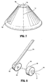
- Armature mechanism 126 includes outer mount 154, a plurality or series of arms 156 coaxially arranged within outer mount 154 and intermediate gears or links 158 which interconnect adjacent arms 156.
- Outer mount 154 may be made of a molded elastomeric material and may define a tapered or frusto-conical configuration as shown. Other configurations for outer mount 154 are also envisioned. Suitable materials for outer mount 154 include polyisoprene or the like.
- Outer mount 154 further has inner portions 160 defining central aperture 162 which permits passage of the surgical instrumentation. In one embodiment, inner portions 160 are adapted to form a seal about the inserted instrument. In the alternative, inner portions 160 may permit passage of the instrument without forming a seal.
- Arms 156 of armature mechanism 126 are preferably disposed within armature housing 124 and concentrically arranged with respect to the mount axis "m” of outer mount 154. Arms 156 extend both longitudinally and radially with respect to the mount axis "m” and portal axis “k”. It is noted upon assembly of armature assembly 110 within main housing 108, mount axis "m", housing axis "b” and portal axis "k" are coincident with each other. In general, arms 156 are adapted to move, flex or pivot from the initial position depicted in FIGS. 5-8 to an activated position upon engagement of armature mechanism 126 with the inserted instrument.
- Arms 156 may be formed of a relatively rigid material, e.g., a material more rigid than the material of fabrication of outer mount 154, such as a rigid polymeric material or a metal including spring steel or the like. Arms 156 include gears 164 at one end. Gears 164 define polygonal opening or recess 166. Intermediate link 158 connecting adjacent arms 156 has a pair of correspondingly dimensioned teeth 168 which are received within polygonal openings 166 of arms 156 to operatively connect the adjacent arms 156. Accordingly, with this arrangement, any movement of one arm 156 causes corresponding rotational movement of intermediate link 158 and thus movement of a connected adjacent arm 156.
- arms 156 and links 158 are fully embedded within outer mount 154.
- outer mount 154 is overmolded onto arms 156 and intermediate links 158.
- Outer mount 154 may function to normally bias arms 156 and links 158 to the initial or rest position of FIG. 4 in which the distal ends of the arms 156 are positioned to intersect the passageway and engage the surgical instrument during insertion thereof.
- the arms 156 bias the instrument to an aligned position with respect to the longitudinal axis "k".
- Armature assembly 110 is mounted to main housing 108 if not an integral component of the housing member 102. In one method, the assembled armature assembly 110 is placed on main housing 108. Locking detents 150 of second housing component 130 are aligned with recesses 122 of main housing 108 to be received therein ( FIG. 2 ). Armature assembly 110 is then rotated to cause locking detents 150 to engage an underside locking surface 172 of main housing 172 to thereby releasably secure armature assembly 110 to main housing 108.
- portal apparatus 100 is introduced into an insufflated abdominal cavity typically utilizing a sharp or non-bladed obturator (not shown) positioned within longitudinal passage 106 of portal apparatus 100.
- the obturator is then removed leaving portal apparatus 100 to thereby define a portal to the underlying tissue within the abdominal cavity.
- an object e.g., a surgical instrument "i” is inserted into armature housing 124 and through armature mechanism 126. Simultaneous with the insertion of the instrument "i”, at least one of arms 156 of armature mechanism 126 is engaged by the instrument "i” and initially moves, flexes or pivots in a radially outward direction relative to housing axis "b".
- arm 156 thereby causes adjacent connecting link 158 to rotate about its axis "t", which in turn causes an adjacent arm 156 to also rotate and move radially outwardly in synchronized manner to an activated position.
- the remaining arms 156 are also caused to simultaneously or concurrently move.
- This simultaneous or concurrent movement functions to maintain or urge the inserted instrument "i” in general alignment with the axis "k” of the portal apparatus 100.
- outer mount 154 is also stressed outwardly relative to mount axis "m” to assume a stressed, e.g., a stretched state. In this condition, outer mount 154 thereby applies a biasing force upon arms 156 to continually urge the arms 156 toward their initial position of FIG. 4 .
- arms 156 Upon removal of the instrument "i", arms 156 return to their initial positions in response to the biasing effect of outer mount 154. Movement of arms 156 to the initial position is also synchronized as effected by the linkage mechanism.
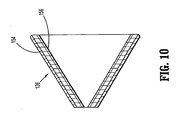
- arms 156 of armature assembly 110 may partially extend from a proximal surface of outer mount 154 as depicted in FIG. 10 to engage the instrument "i" upon insertion through armature assembly 110 thereby providing a degree of protection for the resilient material of the outer mount 154.
- Other variations are also envisioned.
Claims (15)
- Appareil de portail chirurgical (10), qui comprend :un logement de portail (102) ;un élément de portail allongé (104) raccordé au logement de portail (102) et s'étendant de celui-ci, l'élément de portail (104) définissant un axe longitudinal central, le logement de portail (102) et l'élément de portail (104) ayant un perçage axial pour la réception et le passage d'un objet chirurgical etun assemblage d'armature (100) comprenant :au moins deux bras (156) disposés à l'intérieur du logement de portail (102), les au moins deux bras (156) s'étendant au moins radialement vers l'intérieur et étant à même de se déplacer par rapport à l'axe longitudinal d'une position de repos à une position activée au cours du passage de l'objet chirurgical, les au moins deux bras (156) étant raccordés en service de sorte que le mouvement d'un premier bras provoque un mouvement correspondant d'un second bras ;caractérisé en ce qu'il comprend en outré :une monture externe (154) comprenant un matériau résilient et disposée dans le logement de portail (102), la monture externe (154) étant dimensionnée pour enserrer les au moins deux bras, la monture externe (154) étant aménagée pour communiquer une force de sollicitation aux au moins deux bras (156) vers leur position de repos de sorte que les au moins deux bras (156) tendent à presser l'objet chirurgical dans l'alignement général avec l'axe longitudinal central, la monture externe (154) ayant des portions internes définissant un passage pour permettre le passage de l'objet chirurgical.
- Appareil de portail chirurgical (100) selon la revendication 1, comprenant une série de bras (156) aménagés coaxialement autour de l'axe longitudinal central.
- Appareil de portail chirurgical (100) selon la revendication 2, dans lequel la monture externe (154) définit une configuration de forme générale conique.
- Appareil de portail chirurgical (100) selon la revendication 2 ou 3, dans lequel la monture externe (154) définit un tronc de cône.
- Appareil de portail chirurgical (100) selon la revendication 4, dans lequel des bras adjacents (156) sont interconnectés par une roue dentée (164).
- Appareil de portail chirurgical (100) selon l'une quelconque des revendications précédentes, dans lequel les portions internes de la monture externe (154) sont à même d'établir un joint étanche sensible autour de l'objet chirurgical.
- Appareil de portail chirurgical (100) selon l'une quelconque des revendications 2 à 6, dans lequel les bras sont complètement encastrés dans la monture externe (154).
- Appareil de portail chirurgical (100) selon l'une quelconque des revendications 2 à 7, dans lequel les bras (156) sont à même de pivoter entre la position de repos et la position activée.
- Appareil de portail chirurgical (100) selon l'une quelconque des revendications précédentes, dans lequel les bras (156) sont à même d'effectuer un mouvement pivotant synchronisé d'une position de repos à une position activée au cours du passage de l'objet chirurgical.
- Appareil de portail chirurgical (100) selon la revendication 9, dans lequel les bras (156) comprennent une série de roues dentées (164) pour raccorder des bras adjacents (156) en service.
- Appareil de portail chirurgical (100) selon la revendication 9 ou 10, dans lequel la monture externe (154) définit une configuration conique.
- Appareil de portail chirurgical (100) selon la revendication 9, 10 ou 11, dans lequel les portions internes de la monture externe (154) sont à même d'établir une relation hermétique sensible avec l'objet chirurgical.
- Appareil de portail chirurgical (100) selon la revendication 9, 10, 11 ou 12, dans lequel la monture externe (154) définit une surface proximale, les bras (156) s'étendant de la surface proximale pour venir en contact avec l'objet chirurgical au cours du passage à travers la monture externe (154).
- Appareil de portail chirurgical (100) selon l'une quelconque des revendications 9 à 13, dans lequel l'assemblage d'armature (110) peut être monté de manière amovible sur le logement de portail (102).
- Appareil de portail chirurgical (100) selon la revendication 4, dans lequel les bras (156) s'étendent à la fois longitudinalement et radialement par rapport à l'axe longitudinal et sont totalement encastrés dans la monture externe (154) qui définit le tronc de cône.
Applications Claiming Priority (1)
| Application Number | Priority Date | Filing Date | Title |
|---|---|---|---|
| US93180607P | 2007-05-24 | 2007-05-24 |
Publications (2)
| Publication Number | Publication Date |
|---|---|
| EP1994898A1 EP1994898A1 (fr) | 2008-11-26 |
| EP1994898B1 true EP1994898B1 (fr) | 2011-10-19 |
Family
ID=39712112
Family Applications (1)
| Application Number | Title | Priority Date | Filing Date |
|---|---|---|---|
| EP08251791A Expired - Fee Related EP1994898B1 (fr) | 2007-05-24 | 2008-05-22 | Appareil de portail chirurgical avec ensemble d'armature |
Country Status (6)
| Country | Link |
|---|---|
| US (2) | US8137266B2 (fr) |
| EP (1) | EP1994898B1 (fr) |
| JP (2) | JP2008289892A (fr) |
| AU (1) | AU2008202269A1 (fr) |
| CA (1) | CA2631825A1 (fr) |
| ES (1) | ES2375165T3 (fr) |
Families Citing this family (8)
| Publication number | Priority date | Publication date | Assignee | Title |
|---|---|---|---|---|
| MX2011004209A (es) * | 2008-03-27 | 2011-05-24 | Wom Ind Srl | Equipo de instrumental quirurgico apto para cirugia mini invasiva. |
| US20100234688A1 (en) * | 2009-03-10 | 2010-09-16 | Tyco Healthcare Group Lp | Access port including multi-layer seal and suture parks |
| WO2013167717A1 (fr) | 2012-05-09 | 2013-11-14 | EON Surgical Ltd. | Orifice laparoscopique |
| US20140018631A1 (en) * | 2012-07-11 | 2014-01-16 | Covidien Lp | Surgical seal assembly including a guard member |
| US20140336634A1 (en) * | 2013-05-13 | 2014-11-13 | New Wave Surgical Corp. | Multifunctional attachment for electrocautery surgical device |
| USD810290S1 (en) | 2016-01-29 | 2018-02-13 | Medovex Corp. | Surgical portal driver |
| KR101723969B1 (ko) | 2016-03-29 | 2017-04-06 | (주)엘메카 | 카테터 가이드 구조체 |
| US20190059938A1 (en) * | 2017-08-28 | 2019-02-28 | Covidien Lp | Access apparatus including seal component with protective guards |
Family Cites Families (29)
| Publication number | Priority date | Publication date | Assignee | Title |
|---|---|---|---|---|
| US5308336A (en) * | 1982-09-28 | 1994-05-03 | Applied Medical Resources | Seal protection mechanism |
| US4943280A (en) | 1987-12-31 | 1990-07-24 | United States Surgical Corporaiton | Self-seating flapper valve for an insufflation cannula assembly |
| US5127909A (en) | 1990-04-05 | 1992-07-07 | United States Surgical Corporation | Flapper valve for an insufflation cannula assembly |
| US5180373A (en) | 1991-06-07 | 1993-01-19 | United States Surgical Corporation | Valve system for introducing objects into anatomical body portions |
| US5395349A (en) | 1991-12-13 | 1995-03-07 | Endovascular Technologies, Inc. | Dual valve reinforced sheath and method |
| CA2093748C (fr) | 1992-04-24 | 1996-11-12 | Roy D. Gravener | Ensemble de valves permettant d'introduire des instruments dans les cavites du corps |
| US5397314A (en) | 1992-10-09 | 1995-03-14 | Farley; Kevin | Surgical cannula with ball valve |
| US5407433A (en) | 1993-02-10 | 1995-04-18 | Origin Medsystems, Inc. | Gas-tight seal accommodating surgical instruments with a wide range of diameters |
| US5342315A (en) | 1993-04-12 | 1994-08-30 | Ethicon, Inc. | Trocar seal/protector assemblies |
| US5657963A (en) | 1993-06-16 | 1997-08-19 | United States Surgical Corporation | Seal assembly for accommodating introduction of surgical instruments |
| US5492304A (en) | 1993-06-16 | 1996-02-20 | United States Surgical Corporation | Seal assembly for accommodating introduction of surgical instruments |
| US5549565A (en) | 1993-07-13 | 1996-08-27 | Symbiosis Corporation | Reusable surgical trocar with disposable valve assembly |
| CA2126150C (fr) | 1993-07-14 | 2005-02-22 | David T. Green | Montage obturateur facilitant l'introduction d'instruments chirurgicaux |
| US5603702A (en) | 1994-08-08 | 1997-02-18 | United States Surgical Corporation | Valve system for cannula assembly |
| WO1996023536A1 (fr) | 1995-02-03 | 1996-08-08 | Inbae Yoon | Canule a valve en bout |
| US5820600A (en) | 1996-05-14 | 1998-10-13 | Innerdyne, Inc. | Adjustable introducer valve |
| US5727770A (en) | 1997-02-07 | 1998-03-17 | Core Dynamics, Inc. | Double valve cannula seal |
| US6228061B1 (en) | 1998-02-03 | 2001-05-08 | Imagyn Medical Technologies California, Inc. | Trocar seal system having dual seals |
| US6458103B1 (en) | 1998-10-23 | 2002-10-01 | Scimed Life Systems, Inc. | Axially activated hemostasis valve with lumen size selection |
| US6383160B1 (en) | 1999-04-29 | 2002-05-07 | Children's Medical Center Corporation | Variable anti-siphon valve apparatus and method |
| GB0012461D0 (en) | 2000-05-24 | 2000-07-12 | Surgical Innovations Ltd | Surgical seal |
| WO2002030305A2 (fr) | 2000-10-13 | 2002-04-18 | Tyco Healthcare Group Lp | Ensemble valve comprenant une structure de reduction de diametre pour trocart |
| US20060020281A1 (en) | 2000-10-13 | 2006-01-26 | Smith Robert C | Valve assembly including diameter reduction structure for trocar |
| US20030187397A1 (en) * | 2002-03-29 | 2003-10-02 | Dario Vitali | Trocar with a reinforced seal |
| US7056329B2 (en) | 2002-10-23 | 2006-06-06 | Intellimed Surgical Solutions, Llc | Laparoscopic direct vision dissecting port |
| US7195592B2 (en) | 2004-01-27 | 2007-03-27 | Sundaram Ravikumar | Surgical retractor apparatus for use with a surgical port |
| US7063685B2 (en) | 2004-05-12 | 2006-06-20 | C. R. Bard, Inc. | Hemostasis valve for a catheter |
| US8241251B2 (en) * | 2004-08-25 | 2012-08-14 | Tyco Healthcare Group Lp | Gel seal for a surgical trocar apparatus |
| GB2441113A (en) | 2006-08-25 | 2008-02-27 | Surgical Innovations Ltd | Pivoting cannula sealing apparatus |
-
2008
- 2008-05-21 CA CA002631825A patent/CA2631825A1/fr not_active Abandoned
- 2008-05-22 EP EP08251791A patent/EP1994898B1/fr not_active Expired - Fee Related
- 2008-05-22 AU AU2008202269A patent/AU2008202269A1/en not_active Abandoned
- 2008-05-22 ES ES08251791T patent/ES2375165T3/es active Active
- 2008-05-22 US US12/125,143 patent/US8137266B2/en not_active Expired - Fee Related
- 2008-05-23 JP JP2008135915A patent/JP2008289892A/ja not_active Ceased
-
2012
- 2012-02-06 US US13/366,405 patent/US20120203074A1/en not_active Abandoned
- 2012-12-19 JP JP2012276509A patent/JP2013052289A/ja active Pending
Also Published As
| Publication number | Publication date |
|---|---|
| JP2008289892A (ja) | 2008-12-04 |
| EP1994898A1 (fr) | 2008-11-26 |
| AU2008202269A1 (en) | 2008-12-11 |
| JP2013052289A (ja) | 2013-03-21 |
| CA2631825A1 (fr) | 2008-11-24 |
| US20120203074A1 (en) | 2012-08-09 |
| ES2375165T3 (es) | 2012-02-27 |
| US8137266B2 (en) | 2012-03-20 |
| US20080294186A1 (en) | 2008-11-27 |
Similar Documents
| Publication | Publication Date | Title |
|---|---|---|
| AU2008202267B2 (en) | Surgical access apparatus with centering mechanism | |
| EP1709918B1 (fr) | Joint d'étanchéité pour introducteur comprenant un joint de cardan compact | |
| JP5281859B2 (ja) | 外科用アクセスデバイスのためのシールアセンブリ | |
| EP1702574B1 (fr) | Port d'entrée chirurgical avec capacité de rétention améliorée | |
| US20120203074A1 (en) | Surgical portal apparatus with armature assembly | |
| EP1992298B1 (fr) | Canule souple dotée d'un sceau correspondant | |
| AU2009202289A1 (en) | Surgical portal apparatus with waffle seal | |
| US20150112280A1 (en) | Surgical seal assembly | |
| US8409084B2 (en) | Surgical portal apparatus including gear and lockout assembly | |
| EP2351532A1 (fr) | Ensemble hermétique chirurgical | |
| US8414486B2 (en) | Portal apparatus with a finger seal assembly | |
| EP2335623B1 (fr) | Appareil d'accès chirurgical avec mécanisme de contrainte |
Legal Events
| Date | Code | Title | Description |
|---|---|---|---|
| PUAI | Public reference made under article 153(3) epc to a published international application that has entered the european phase |
Free format text: ORIGINAL CODE: 0009012 |
|
| AK | Designated contracting states |
Kind code of ref document: A1 Designated state(s): AT BE BG CH CY CZ DE DK EE ES FI FR GB GR HR HU IE IS IT LI LT LU LV MC MT NL NO PL PT RO SE SI SK TR |
|
| AX | Request for extension of the european patent |
Extension state: AL BA MK RS |
|
| 17P | Request for examination filed |
Effective date: 20090511 |
|
| 17Q | First examination report despatched |
Effective date: 20090616 |
|
| AKX | Designation fees paid |
Designated state(s): DE ES FR GB IE IT |
|
| GRAP | Despatch of communication of intention to grant a patent |
Free format text: ORIGINAL CODE: EPIDOSNIGR1 |
|
| RIN1 | Information on inventor provided before grant (corrected) |
Inventor name: BROCKMEIER, OIVIND Inventor name: FOCHT, KENNETH ALLEN Inventor name: JUDSON, JARED ALDEN |
|
| GRAS | Grant fee paid |
Free format text: ORIGINAL CODE: EPIDOSNIGR3 |
|
| GRAA | (expected) grant |
Free format text: ORIGINAL CODE: 0009210 |
|
| AK | Designated contracting states |
Kind code of ref document: B1 Designated state(s): DE ES FR GB IE IT |
|
| REG | Reference to a national code |
Ref country code: GB Ref legal event code: FG4D |
|
| REG | Reference to a national code |
Ref country code: IE Ref legal event code: FG4D |
|
| RAP2 | Party data changed (patent owner data changed or rights of a patent transferred) |
Owner name: TYCO HEALTHCARE GROUP, LP |
|
| REG | Reference to a national code |
Ref country code: DE Ref legal event code: R096 Ref document number: 602008010573 Country of ref document: DE Effective date: 20111229 |
|
| REG | Reference to a national code |
Ref country code: ES Ref legal event code: FG2A Ref document number: 2375165 Country of ref document: ES Kind code of ref document: T3 Effective date: 20120227 |
|
| PLBE | No opposition filed within time limit |
Free format text: ORIGINAL CODE: 0009261 |
|
| STAA | Information on the status of an ep patent application or granted ep patent |
Free format text: STATUS: NO OPPOSITION FILED WITHIN TIME LIMIT |
|
| 26N | No opposition filed |
Effective date: 20120720 |
|
| REG | Reference to a national code |
Ref country code: DE Ref legal event code: R097 Ref document number: 602008010573 Country of ref document: DE Effective date: 20120720 |
|
| PGFP | Annual fee paid to national office [announced via postgrant information from national office to epo] |
Ref country code: ES Payment date: 20120528 Year of fee payment: 5 |
|
| PGFP | Annual fee paid to national office [announced via postgrant information from national office to epo] |
Ref country code: IT Payment date: 20130522 Year of fee payment: 6 |
|
| PG25 | Lapsed in a contracting state [announced via postgrant information from national office to epo] |
Ref country code: IT Free format text: LAPSE BECAUSE OF NON-PAYMENT OF DUE FEES Effective date: 20140522 |
|
| REG | Reference to a national code |
Ref country code: ES Ref legal event code: FD2A Effective date: 20151030 |
|
| PG25 | Lapsed in a contracting state [announced via postgrant information from national office to epo] |
Ref country code: ES Free format text: LAPSE BECAUSE OF NON-PAYMENT OF DUE FEES Effective date: 20140523 |
|
| REG | Reference to a national code |
Ref country code: FR Ref legal event code: PLFP Year of fee payment: 9 |
|
| REG | Reference to a national code |
Ref country code: FR Ref legal event code: PLFP Year of fee payment: 10 |
|
| PGFP | Annual fee paid to national office [announced via postgrant information from national office to epo] |
Ref country code: FR Payment date: 20170421 Year of fee payment: 10 Ref country code: GB Payment date: 20170426 Year of fee payment: 10 Ref country code: IE Payment date: 20170421 Year of fee payment: 10 Ref country code: DE Payment date: 20170420 Year of fee payment: 10 |
|
| REG | Reference to a national code |
Ref country code: DE Ref legal event code: R119 Ref document number: 602008010573 Country of ref document: DE |
|
| GBPC | Gb: european patent ceased through non-payment of renewal fee |
Effective date: 20180522 |
|
| REG | Reference to a national code |
Ref country code: IE Ref legal event code: MM4A |
|
| PG25 | Lapsed in a contracting state [announced via postgrant information from national office to epo] |
Ref country code: DE Free format text: LAPSE BECAUSE OF NON-PAYMENT OF DUE FEES Effective date: 20181201 Ref country code: IE Free format text: LAPSE BECAUSE OF NON-PAYMENT OF DUE FEES Effective date: 20180522 Ref country code: FR Free format text: LAPSE BECAUSE OF NON-PAYMENT OF DUE FEES Effective date: 20180531 Ref country code: GB Free format text: LAPSE BECAUSE OF NON-PAYMENT OF DUE FEES Effective date: 20180522 |