EP1994403B1 - Analysis of substance mixtures - Google Patents
Analysis of substance mixtures Download PDFInfo
- Publication number
- EP1994403B1 EP1994403B1 EP06805440.2A EP06805440A EP1994403B1 EP 1994403 B1 EP1994403 B1 EP 1994403B1 EP 06805440 A EP06805440 A EP 06805440A EP 1994403 B1 EP1994403 B1 EP 1994403B1
- Authority
- EP
- European Patent Office
- Prior art keywords
- analysis
- evaluation device
- substance
- mixtures
- substances
- Prior art date
- Legal status (The legal status is an assumption and is not a legal conclusion. Google has not performed a legal analysis and makes no representation as to the accuracy of the status listed.)
- Not-in-force
Links
- 239000000126 substance Substances 0.000 title claims description 155
- 239000000203 mixture Substances 0.000 title claims description 149
- 238000004458 analytical method Methods 0.000 title claims description 52
- 238000011156 evaluation Methods 0.000 claims description 38
- 238000000034 method Methods 0.000 claims description 33
- 238000001514 detection method Methods 0.000 claims description 11
- 238000009826 distribution Methods 0.000 claims description 8
- 230000001360 synchronised effect Effects 0.000 claims description 5
- 239000012530 fluid Substances 0.000 claims 1
- 238000002347 injection Methods 0.000 description 55
- 239000007924 injection Substances 0.000 description 55
- 239000007789 gas Substances 0.000 description 50
- 239000000523 sample Substances 0.000 description 25
- 239000012491 analyte Substances 0.000 description 21
- 238000000926 separation method Methods 0.000 description 15
- 239000011159 matrix material Substances 0.000 description 11
- 238000010438 heat treatment Methods 0.000 description 9
- 238000010586 diagram Methods 0.000 description 8
- 238000001208 nuclear magnetic resonance pulse sequence Methods 0.000 description 8
- 230000009466 transformation Effects 0.000 description 7
- 239000011521 glass Substances 0.000 description 6
- 238000011002 quantification Methods 0.000 description 6
- 239000000243 solution Substances 0.000 description 6
- 238000001704 evaporation Methods 0.000 description 5
- 230000008020 evaporation Effects 0.000 description 5
- 238000011010 flushing procedure Methods 0.000 description 5
- 239000011261 inert gas Substances 0.000 description 5
- 101100129500 Caenorhabditis elegans max-2 gene Proteins 0.000 description 4
- 239000002184 metal Substances 0.000 description 4
- 238000001228 spectrum Methods 0.000 description 4
- 230000008901 benefit Effects 0.000 description 3
- 230000008859 change Effects 0.000 description 3
- 239000005350 fused silica glass Substances 0.000 description 3
- 230000006872 improvement Effects 0.000 description 3
- 238000004566 IR spectroscopy Methods 0.000 description 2
- 238000005481 NMR spectroscopy Methods 0.000 description 2
- 108010026552 Proteome Proteins 0.000 description 2
- 238000011001 backwashing Methods 0.000 description 2
- 150000001875 compounds Chemical class 0.000 description 2
- 238000013461 design Methods 0.000 description 2
- 238000002474 experimental method Methods 0.000 description 2
- 238000004817 gas chromatography Methods 0.000 description 2
- 238000004811 liquid chromatography Methods 0.000 description 2
- 230000014759 maintenance of location Effects 0.000 description 2
- 238000004451 qualitative analysis Methods 0.000 description 2
- 238000004445 quantitative analysis Methods 0.000 description 2
- 238000004252 FT/ICR mass spectrometry Methods 0.000 description 1
- 238000005033 Fourier transform infrared spectroscopy Methods 0.000 description 1
- VYPSYNLAJGMNEJ-UHFFFAOYSA-N Silicium dioxide Chemical compound O=[Si]=O VYPSYNLAJGMNEJ-UHFFFAOYSA-N 0.000 description 1
- 230000006978 adaptation Effects 0.000 description 1
- 238000002306 biochemical method Methods 0.000 description 1
- 238000004364 calculation method Methods 0.000 description 1
- 238000005251 capillar electrophoresis Methods 0.000 description 1
- 239000012159 carrier gas Substances 0.000 description 1
- 238000013375 chromatographic separation Methods 0.000 description 1
- 238000004587 chromatography analysis Methods 0.000 description 1
- 239000000470 constituent Substances 0.000 description 1
- 238000011109 contamination Methods 0.000 description 1
- 238000006073 displacement reaction Methods 0.000 description 1
- 238000005315 distribution function Methods 0.000 description 1
- 238000000605 extraction Methods 0.000 description 1
- 230000008014 freezing Effects 0.000 description 1
- 238000007710 freezing Methods 0.000 description 1
- 238000000227 grinding Methods 0.000 description 1
- 238000011835 investigation Methods 0.000 description 1
- 239000007788 liquid Substances 0.000 description 1
- 238000004949 mass spectrometry Methods 0.000 description 1
- 238000005259 measurement Methods 0.000 description 1
- 229910001092 metal group alloy Inorganic materials 0.000 description 1
- 239000005445 natural material Substances 0.000 description 1
- 239000002245 particle Substances 0.000 description 1
- 238000000053 physical method Methods 0.000 description 1
- 230000008569 process Effects 0.000 description 1
- 108090000765 processed proteins & peptides Proteins 0.000 description 1
- 102000004196 processed proteins & peptides Human genes 0.000 description 1
- 108090000623 proteins and genes Proteins 0.000 description 1
- 102000004169 proteins and genes Human genes 0.000 description 1
- 230000003252 repetitive effect Effects 0.000 description 1
- 230000035945 sensitivity Effects 0.000 description 1
- 238000004611 spectroscopical analysis Methods 0.000 description 1
- 239000007858 starting material Substances 0.000 description 1
- 230000002123 temporal effect Effects 0.000 description 1
- 230000002103 transcriptional effect Effects 0.000 description 1
Images


Classifications
-
- G—PHYSICS
- G01—MEASURING; TESTING
- G01N—INVESTIGATING OR ANALYSING MATERIALS BY DETERMINING THEIR CHEMICAL OR PHYSICAL PROPERTIES
- G01N30/00—Investigating or analysing materials by separation into components using adsorption, absorption or similar phenomena or using ion-exchange, e.g. chromatography or field flow fractionation
- G01N30/02—Column chromatography
- G01N30/04—Preparation or injection of sample to be analysed
- G01N30/16—Injection
- G01N30/20—Injection using a sampling valve
-
- G—PHYSICS
- G01—MEASURING; TESTING
- G01N—INVESTIGATING OR ANALYSING MATERIALS BY DETERMINING THEIR CHEMICAL OR PHYSICAL PROPERTIES
- G01N30/00—Investigating or analysing materials by separation into components using adsorption, absorption or similar phenomena or using ion-exchange, e.g. chromatography or field flow fractionation
- G01N30/02—Column chromatography
- G01N30/26—Conditioning of the fluid carrier; Flow patterns
- G01N30/38—Flow patterns
- G01N30/46—Flow patterns using more than one column
- G01N30/461—Flow patterns using more than one column with serial coupling of separation columns
- G01N30/463—Flow patterns using more than one column with serial coupling of separation columns for multidimensional chromatography
-
- G—PHYSICS
- G01—MEASURING; TESTING
- G01N—INVESTIGATING OR ANALYSING MATERIALS BY DETERMINING THEIR CHEMICAL OR PHYSICAL PROPERTIES
- G01N30/00—Investigating or analysing materials by separation into components using adsorption, absorption or similar phenomena or using ion-exchange, e.g. chromatography or field flow fractionation
- G01N30/02—Column chromatography
- G01N30/04—Preparation or injection of sample to be analysed
- G01N30/06—Preparation
- G01N30/12—Preparation by evaporation
- G01N2030/121—Preparation by evaporation cooling; cold traps
- G01N2030/123—Preparation by evaporation cooling; cold traps using more than one trap
-
- G—PHYSICS
- G01—MEASURING; TESTING
- G01N—INVESTIGATING OR ANALYSING MATERIALS BY DETERMINING THEIR CHEMICAL OR PHYSICAL PROPERTIES
- G01N30/00—Investigating or analysing materials by separation into components using adsorption, absorption or similar phenomena or using ion-exchange, e.g. chromatography or field flow fractionation
- G01N30/02—Column chromatography
- G01N30/62—Detectors specially adapted therefor
- G01N2030/621—Detectors specially adapted therefor signal-to-noise ratio
- G01N2030/623—Detectors specially adapted therefor signal-to-noise ratio by modulation of sample feed or detector response
-
- G—PHYSICS
- G01—MEASURING; TESTING
- G01N—INVESTIGATING OR ANALYSING MATERIALS BY DETERMINING THEIR CHEMICAL OR PHYSICAL PROPERTIES
- G01N30/00—Investigating or analysing materials by separation into components using adsorption, absorption or similar phenomena or using ion-exchange, e.g. chromatography or field flow fractionation
- G01N30/02—Column chromatography
- G01N30/86—Signal analysis
- G01N30/8658—Optimising operation parameters
Definitions
- the present invention relates to a method for the analysis of mixtures of substances, in particular complex chemical and / or biochemical mixtures, wherein a substance mixture to be analyzed is fed to a separation device, by chemically and / or physically effected transport, the substances of the substance mixture to be analyzed separated from each other by the separator and the separated substances are detected by an evaluation device.
- the present invention relates to methods for producing pulsed substance mixtures, in particular complex chemical and / or biochemical mixtures, preferably for use with an analysis according to the invention of mixtures, in particular complex chemical and / or biochemical mixtures.
- Proteins, peptides and / or the like biochemically relevant, for example, in a so-called genome, proteome, metabolome, and / or transcriptional analysis compounds to be analyzed, in particular chromatographic or electrophoretic separation methods and / or devices are used, the analyzed Mixtures are analyzed sequentially and / or in parallel.
- the separation devices are also coupled or connected for analysis usually with an evaluation device for detecting or detecting the separated substances of the mixture.
- an evaluation device for detecting or detecting the separated substances of the mixture.
- spectroscopic and / or spectrometric detection techniques are used on the part of the evaluation devices or detectors, in particular spectroscopic detectors in connection with genome, proteome, metabolome and / or transcriptome analyzes, for example in nuclear magnetic resonance (NMR) or infrared spectroscopy (IR) , and mass spectrometric (MS) detectors are used.
- NMR nuclear magnetic resonance
- IR infrared spectroscopy
- MS mass spectrometric
- the hitherto known methods and devices for the analysis of substance mixtures have various disadvantages.
- the previously known, in particular high-resolution spectroscopic and / or spectrometric techniques using methods and devices due to large analysis periods and low detection sensitivities or poor signal-to-noise ratios (SNRs) of the Use of upcoming evaluation facilities limited.
- SNRs signal-to-noise ratios
- an analysis of very small amounts of substance is not possible in the detection of the entire spectroscopic or spectrometric range of a substance mixture to be analyzed.
- the throughput of mixtures to be analyzed is severely limited, in particular due to the previously required large analysis periods.
- the qualitative and quantitative analysis of the starting materials and products of a 7-by-7 parallel reactor requires about 24.5 hours with an analysis time of about 30 minutes.
- the object of the present invention is to improve the analysis of substance mixtures while avoiding the described disadvantages, in particular with regard to analysis duration, throughput and resolution.
- the method according to claim 1 is proposed with the present invention.
- the invention is based on the finding that by using a mixture of substances to be analyzed with pulses of a unique binary sequence, that is, an arbitrary sequence of zeros ("0") and ones ("1"), one with an identifier, in particular after Is given type of bar code, provided substance mixture to be analyzed, so that at the same time different mixtures - almost in the manner of a multiplexing method, similar to US 2004/0144918 A1 for applications in spectroscopy (FT-NMR, FT-IR) and mass spectrometry (FT-ICR-MS and HT-TOF-MS) - can be fed to the analysis, which in particular the analysis time, the substance mixture throughput to be analyzed and the resolution improve the analyzed substances.
- FT-NMR, FT-IR spectroscopy
- FT-ICR-MS and HT-TOF-MS mass spectrometry
- the pulses of the substance mixture to be analyzed are supplied separated in time and space from one another to the separating device.
- the unique binary sequence is formed from a sequence which is subdivided with a repeating sequence and generated with a binary random number generator.
- the unique binary sequence consists of 2 n elements, with 0 ⁇ n ⁇ ⁇ (at least theoretically), preferably with 5 ⁇ n ⁇ 128, particularly preferably with 7 ⁇ n ⁇ 14.
- the invention makes up the To realize that n analyzes can be performed in the same time as a conventional analysis.
- the signal-to-noise ratio (SNR) can be improved in a range of n 2 ⁇ SNR ⁇ n 2 .
- the maximum achievable improvement of the signal-to-noise ratio (SNRs) is accordingly / 2 n ,
- the longer the pulse sequences used the greater the advantage in the signal-to-noise ratio (SNR), the so-called Felgett advantage, and accordingly improves the resolution and the uniqueness of the assignment of the signals of the detected by the evaluation unit substances.
- the invention is characterized by a modulation interval with a sequence or pulse interval duration ( ⁇ t) in a range from about 1 s to about 20 s and a pulse duration ( ⁇ t pulse ) in a range of about 1 ms to about 10 ms.
- ⁇ t sequence or pulse interval duration
- ⁇ t pulse pulse duration
- the substance detection of the evaluation device is synchronized with the substance mixture supply.
- the evaluation device is operated with a detection duration that corresponds to the pulse interval duration ( ⁇ t) or an integral fraction of the pulse interval duration ( ⁇ t).
- detectors can advantageously be used by the evaluation device for detecting the substances of the substance mixture to be analyzed, which are operated in comparison with the pulse interval duration ( ⁇ t) with lower acquisition times, that is, in particular, more slowly. According to the invention, it is thus advantageously possible to detect substances of the substance mixture to be analyzed in the entire detection range of the detector of the evaluation device.
- a particularly advantageous embodiment of the invention provides that the substances detected by the evaluation device are mathematically deconvoluted with the unique binary sequence of the pulses of the substance mixture to be analyzed, preferably by a two-dimensional mathematical deconvolution.
- the substances detected by the evaluation device undergo a Hadamard transformation with the unique binary sequence
- the concentration distributions of the substances detected by the evaluation device are determined from the result of the Hadamard transformation
- the concentrations of the individual substances detected by the evaluation device are determined , Preferably by solving one of the concentration distributions, the concentrations of the individual detected by the evaluation device substances and the substances detected by the evaluation device formed linear equation system according to the concentrations of the individual detected by the evaluation Substances.
- the respective spectra of the substances of the substance mixture can advantageously be determined for identification and quantification as a function of their respective retention time, advantageously providing an improved signal-to-analysis method compared to previously known, in particular continuously operated analysis methods.
- Noise ratio (SNR) and an improved detection limit is achieved.
- the Hadamard transformation (HT) advantageously makes it possible to multiplex the substance mixture to be analyzed, with which advantageously up to three discrete states ("-1", "0", “+1") can be coded.
- the substance mixture to be analyzed is encoded as a wave or particle packet with the binary pseudorandom sequences (modulation sequence).
- the Hadamard matrix it is advantageously possible to use a simplex matrix derived therefrom which encodes only two discrete states ("0", "1") and can be obtained from the Hadamard matrix by simple transformation as follows:
- the separation device uses chromatographic and / or electrophoretic separation methods and is preferably a gas chromatograph or a supercritical liquid chromatograph.
- the evaluation device comprises at least one detector and / or at least one spectroscopic and / or spectrometric detector.
- At least one substance mixture is continuously fed to at least one channel via at least one capillary line, the mixture is evaporated in at least one deactivated glass tube arranged in the at least one channel, the at least one channel is acted upon by a gas flow via a switchable pressure valve and injected with the gas flow vaporized substance mixture from the at least one channel in a needle.
- the switchable pressure valve is switched with pulses of a unique binary sequence.
- switching times of the switchable pressure valve are provided in a range from 1 ms to about 10 ms.
- An apparatus for carrying out the method of the invention provides for an admission of the vaporized substance mixture with a gas flow of a gas and / or a gas mixture which changes the composition of the evaporated mixture, particularly preferably with an inert gas and / or inert gas mixture.
- the at least one channel and / or the needle is flushed by being exposed to the gas flow, preferably controlled by the switchable pressure valve of the channel.
- An embodiment of a device with at least two channels injecting into the needle provides that the respective switchable pressure valves of the channels are controlled synchronously and / or separately from one another.
- the evaporation of the mixture is controlled, preferably by controlling the temperature of a heater for evaporation of the mixture.
- the pressure of the gas flow is controlled.
- a device for generating pulsed substance mixtures, in particular complex chemical and / or biochemical substance mixtures, which is characterized by at least one channel with at least one capillary line for supplying at least one substance mixture into the channel, with at least one deactivated glass tube arranged in the channel Evaporation of the at least one mixture supplied to the channel in the channel with a heater and with a switchable pressure valve for connection of the channel to a gas supply for acting on the at least one vaporized mixture with a gas flow, and one to the at least one channel fluidly subsequent output to connect a Gas discharge, preferably an injection needle.
- the inflow direction of the gas flow for the admission of the at least one vaporized substance mixture is substantially perpendicular to the longitudinal direction of the channel.
- the gas supply line can be connected via the switchable pressure valve approximately centrally of the longitudinal extension direction of the channel to the channel.
- a further embodiment of a device provides that the heating device is arranged at least in the region of the inactivated glass tube arranged in the channel, wherein the heating device is preferably designed in the form of an exchangeable heating cartridge.
- the design allows so in particular a simple and quick replacement of the heater.
- a further advantageous embodiment provides the use of at least one sensor element for detecting the temperature of the heating device and / or the evaporation, wherein the detected temperature is preferably usable for controlling the heating device.
- the pressure valve of the device with switching times in a range of about 1 ms to about 10 ms, switchable.
- the at least one capillary of the device is advantageously made of metal, glass and / or fused silica glass.
- the device is advantageously made of metal and / or a metallic alloy, preferably in one piece.
- the method according to the invention and the apparatus for producing pulsed substance mixtures are used with an analysis method according to the invention, wherein the substance mixture to be analyzed is supplied via the needle to the separation device or can be fed.
- a continuous substance mixture stream one after the other by at least two separate chambers, wherein in the first chamber, a focus of the substance mixture flow and in the second chamber, a modulation of the focused substance mixture flow with pulses of a unique binary sequence.
- the focus of the substance mixture stream and / or the modulation of the focused substance mixture stream by means of a cold and hot gas stream the mixture of substances is first frozen out and then released by rapid heating again.
- the chambers each have at least one cold gas jet nozzle and at least one hot gas jet nozzle, the nozzle openings of which allow a substantially perpendicular to the flow direction of the mixture mixture flow through the respective chamber cold relationship way hot gas flow.
- the nozzle openings of the at least one cold gas jet nozzle and the at least one hot gas jet nozzle of the respective chambers enable a flow which is substantially perpendicular to one another.
- the cold and / or Warmgasjetdüsen the respective chambers are advantageously operated with gas flows of up to 40 l / min.
- a further embodiment provides that at least the nozzles of the chamber enabling a modulation of the focused substance mixture flow are actuated with switching times in a range from approximately 1 ms to approximately 10 ms.
- the nozzles of the at least two chambers are separated and controlled independently.
- the nozzles of the at least two chambers are controlled synchronized, preferably driven with different sequences.
- Another embodiment provides for changes in the composition of the evaporated mixture excluding Gas flow of a gas and / or a gas mixture for the cold and / or hot gas stream before, particularly preferably realized by using an inert gas and / or inert gas mixture.
- the pressure of the respective gas flow is controlled.
- a device for generating pulsed substance mixtures, in particular complex chemical and / or biochemical substance mixtures, a device is further proposed, which is characterized by at least two mutually separate, each having an input and an output having chambers for guiding a continuous substance mixture flow through the respective chamber the chambers are arranged one after the other in the direction of flow of the substance mixture flow through the chambers and wherein the chambers each have at least one cold gas jet nozzle and at least one hot gas jet nozzle whose nozzle openings allow a cold or hot gas flow which is substantially perpendicular to the flow direction of the substance mixture flow through the respective chamber.
- the nozzle openings of the at least one cold gas jet nozzle and the at least one hot gas jet nozzle of the respective chambers are designed to allow a substantially mutually perpendicular flow.
- the cold and / or Warmgasjetdüsen the respective chambers with gas flows of up to 40 l / min are operable.
- the first chamber formed in the flow direction of the substance mixture flow is designed to enable focusing of the substance mixture flow
- the second chamber in the flow direction of the substance mixture flow is to enable a modulation of the focused substance mixture flow with pulses of a unique binary sequence
- At least the nozzles of the modulation of the focused substance mixture flow enabling chamber with switching times in a range of about 1 ms to about 10 ms, controllable.
- the further method according to the invention and the device for producing pulsed substance mixtures are used with an analysis method according to the invention wherein the substance mixture to be analyzed is supplied via the output of the second chamber of the separation device or can be fed.
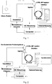
- Fig. 1 and Fig. 2 each show in a schematic schematic representation of an embodiment of the basic structure of an arrangement for carrying out an inventive analysis of mixtures, in particular complex chemical and / or biochemical mixtures.
- This is a coming from a chemical reactor to be analyzed Mixture fed as a continuous stream of a device (injector) for generating pulsed mixtures.
- a device injector
- Exemplary embodiments of corresponding devices for producing pulsed substance mixtures are disclosed in US Pat Fig. 3 to Fig. 7 and are explained in more detail below in connection with these.
- the continuous substance mixture flow of the substance mixture to be analyzed is in the embodiment according to Fig. 1 supplied by a chemical reactor.
- the mixed substance pulses generated by the pulsed substance generating device are then applied to the fused-silica (fs-column) column of a separator gas chromatograph (GC).
- a separator gas chromatograph On the part of the gas chromatograph (GC), the substances of the substance mixture to be analyzed are separated from one another. The separated substances are then detected by an evaluation device.
- the evaluation device is in the in Fig. 1 illustrated embodiment formed by a detector of the gas chromatograph. At the in Fig. 2 In the embodiment shown, the evaluation device is a spectrometer coupled to the gas chromatograph (GC).
- a control device of the gas chromatograph (GC)
- a data acquisition device and one used by the device (injector) for generating mixed substance pulses as a modulator, connected to an amplifier means (modulation sequence) to produce a unique binary sequence of the substance mixture pulses
- a computing device connected to the components (computer).
- a precise control of the injection of the substance mixture (analytes) into the chromatographic separation system is required.
- this control comprises a precise and defined time control of the time interval between successive injections of the pulsed substance mixture into the separation device (gas chromatographs) and the duration of injection within such a time interval.
- a precise and defined control of the quantity of the substance mixture (sample quantity) is required.
- valve circuits used hitherto in the state of the art for generating pulsed substance mixtures are slow and the control of the sample volume is inflexible, in particular by sample grinding. Furthermore, pressure pulses occur due to a valve circuit coupled directly to the chromatographic system, which leads to so-called system peaks in the chromatogram, since no continuous flow occurs in the chromatographic system.
- Fig. 1 and Fig. 2 used device (injector cf-SSL-MP injector) for generating pulsed mixtures, preferably for gas chromatography (GC) (see. Fig. 1 and Fig. 2 ) can be connected to a split / splitless injector of the gas chromatograph by simple mounting.
- GC gas chromatography
- SFC supercritical liquid chromatography
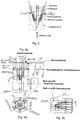
- Fig. 3 and Fig. 4a to 4c such as Fig. 5 and Fig. 6a to 6c each show an exemplary embodiment of a device (injector, cf-SSL-MP injector) for generating pulsed mixtures of substances.
- a device injector, cf-SSL-MP injector
- a substance mixture to be analyzed can be injected into a separating device.
- the embodiment according to Fig. 5 and Fig. 6a to 6c allows a switched injecting of up to seven mixtures.
- the devices each consist of a heatable metal block (sample block), with holes for the respective injection channels - in the embodiment according to Fig. 3 and Fig. 4a to 4c an injection channel and in the embodiment according to Fig. 5 and Fig. 6a to 6c seven injection channels (sample channels) -. is provided.
- the injection channels take capillary lines of the respective substance mixture to be analyzed, ie the respective sample source, preferably from a parallelized reactor, multi-well plates or similar source.
- the sample block has heating devices and thermocouples for exact temperature control.
- Each injection channel (sample channel) has a gas supply line that can be controlled with a fast pressure valve with switching times in the millisecond range.
- this gas supply line can also be used as flushing line of the respective sample channel.
- the flushing can also be controlled with the controllable or switchable pressure valve.
- the respective gas supply lines can be controlled individually and or synchronously.
- the injection of the analyte mixture into a needle that takes place in the existing split / splittless injector of the separator, at Fig. 1 and Fig. 2 of the gas chromatograph is introduced and is there and is heated by the injector.
- the respective configuration of the devices for generating pulsed mixtures according to Fig. 3 and Fig. 4a to 4c respectively Fig. 5 and Fig. 6a to 6c , So with an injection channel (sample channel) in the embodiment according to Fig. 3 and Fig. 4a to 4c or with seven injection channels (sample channels) in the embodiment according to Fig. 5 and Fig. 6a to 6c , Moreover, allows the possibility of flushing the injection needle by a carrier gas flow, in this case in the range of ml / min, the separator (gas chromatograph). This achieves a permanent flushing and avoids contamination of the different substance mixtures (analyte mixtures) to be analyzed by means of multiplexing.
- such additional grit flow is adjustable at the respective injection valves (backwashing) and / or at a split output integrated in the heating block.
- the total chippings flow results from the sum of the respective flows at the valves.
- the volume between the injection needle and the evaporation space of the respective capillaries is advantageously minimized in such an arrangement, in particular in order to avoid dead volumes.
- the pressure surge outside the Injector of the separator takes place and is intercepted by the pressure control of the separator (gas chromatograph) or the split system, occur advantageously no pressure fluctuations in the separation by the device (cf-SSL-MP injector).
- Fig. 7 shows a further embodiment of an apparatus for generating pulsed mixtures.
- the continuous stream of a substance mixture to be analyzed directly on the separation column of a separation device present, as in Fig. 1 and Fig. 2 represented by the gas chromatograph, modulated by a double-focusing cryogenic modulator.
- the in Fig. 7 illustrated in the basic structure allows in particular an inventive usable for two-dimensional separation techniques coding of the substance mixture to be analyzed.
- the column temperature modulator has two separate modulation chambers.
- the first chamber reaches the focusing of the substance mixture (analyte) to be analyzed
- the modulation of the substance mixture (analyte) to be analyzed takes place according to a binary pseudorandom sequence, which differs from the one in Fig. 1 and Fig. 2 computer unit shown and / or a separate device for generating a corresponding modulation sequence is generated.
- a binary pseudorandom sequence which differs from the one in Fig. 1 and Fig. 2 computer unit shown and / or a separate device for generating a corresponding modulation sequence is generated.
- FIGS. 8 and 10 each show a plot of measured injection stability of a unique binary sequence of a pulsed mixture over time.
- Fig. 9 shows an enlarged section of the diagram Fig. 8 , Based on Fig. 9 is clearly the stability of the peak areas of three different mixtures (analytes) recognizable.
- Fig. 9 shows an enlarged section of the diagram Fig. 8 , Based on Fig. 9 is clearly the stability
- the pulse duration can be selected short compared to the injection interval, a multiple injection within an injection interval is advantageously possible (oversampling), as a result of which the throughput of substance mixtures to be analyzed (sample throughput) can be increased further.
- the device for generating pulsed mixtures of substances shown in particular in connection with the in Fig. 1 illustrated arrangement for the analysis of mixtures a high-throughput analysis feasible.
- mixtures of substances (analyte samples) to be analyzed are coded with a unique binary sequence.
- Fig. 11 shows in a schematic representation corresponding injection sections for samples A1 to A13 within a binary pseudorandom sequence.
- the injection sequence consists of the same number of elements 0 and 1 or the number can differ by 1 (2 n -1).
- Injection sections of the samples A1 to A13 illustrated by way of example can also be subdivided into calibration and measurement areas in order to enable continuous quantification with internal standardization.
- An element 1 in the binary pseudorandom sequence represents an injection in the form of an injection pulse. For an element 0, no injection takes place.
- the respective elements can additionally be subdivided into submodulation sequences, which are constructed identically for all elements, advantageously in order to enable or guarantee multiple injections (oversampling).
- a substance mixture to be analyzed is coded with a unique binary sequence.
- the coding of the analyte sample is carried out by injection device according to 3 and FIGS. 4a to 4c) or low temperature modulation (device according to Fig.
- the injection sequence consists of the same number of elements 0 and 1 or the number can differ by 1 (2 n -1).
- element 1 a sample is injected or released through the hot air jet.
- element 0 there is no injection or freezing by the cold air jet.
- the injection intervals are calculated according to the required time for a so-called full scan or one Multiples of the duration of a so-called full scan of the spectrometer selected.
- the scan (acquisition) of the spectrometer and the injection interval are synchronized with each other.
- the injection pulse duration or modulation duration in the case of the low-temperature modulator can be chosen to be equal to or shorter than the injection interval or the modulation interval.
- each injection interval or modulation interval advantageously also several different spectroscopic or spectrometric experiments can be performed.
- a bulk full scan and MS / MS or MS n experiments are performed for unambiguous identification and quantification.
- Fig. 12 shows in a diagram the temporal gradual change in concentration of a substance mixture to be analyzed (analyte) as a total chromatogram recorded by the evaluation device.
- the corresponding data of the overall chromatogram are provided by the evaluation device and / or by a data acquisition device (cf. Fig. 1 and Fig. 2 ) in front.
- the raw data are used by means of a computing device (computer) of the evaluation device, in particular as part of a deconvolution for further evaluation.
- an overall chromatogram (cf. Fig. 12 and Fig. 13 ), which is a superposition of n single chromatograms.
- the direct multiplication of the raw data in the circular representation (after 2 n -1 time intervals, the signal intensity is added back to the vector elements at the beginning) with the inverse Hadamard, simplex or inverse matrix of the known binary pseudorandom sequence gives the total chromatogram (cf. Fig. 13 ) of the respective analytes.
- the number k max of the different analytes in the respective samples i and the respective peak shapes results from the overall chromatogram.
- a very good resolution of the peaks is achieved with the embodiments of the analysis method according to the invention, so that the method can also be applied to problems with small separation factors, as occur, for example, in enantiomer separations for determining the enantiomeric excess.
- this overall chromatogram (cf. Fig. 12 ) is characterized by deviations in the baseline, which in turn represents a convolution of the respective analyte concentrations. Therefore, first, a peak shape analysis is performed to obtain the distribution function ⁇ (A k ) of the respective analytes as a function of time. The maximum of each individual analyte peak is normalized to 1.
- Each line represents the sum of the relative concentrations of the respective analytes in the samples.
- This procedure can be applied to the crude chromatogram in the circular and non-circular representation.
- the respective concentration of the analytes results as a concentration vector which, multiplied by the concentration distribution matrix, yields the signal intensities in each time interval of the crude chromatogram.
- the solution is the concentration of the respective analytes in the samples i.
- the crude chromatogram is converted by means of iterative adaptation with the concentration vector (by forming the difference or by division) and subsequent Hadamard transformation into an overall chromatogram whose deviations in the baseline through further fine tuning steps be minimized in the solution of the linear equation system.
- Fig. 13 shows on the right side the concentration of the analytes of the respective samples in a circular representation.
Description
Die vorliegende Erfindung betrifft ein Verfahren zur Analyse von Stoffgemischen, insbesondere komplexen chemischen und/oder biochemischen Stoffgemischen, wobei ein zu analysierendes Stoffgemisch einer Trenneinrichtung zugeführt wird, durch chemisch und/oder physikalisch bewirkten Transport die Stoffe des zu analysierenden Stoffgemisches seitens der Trenneinrichtung voneinander getrennt werden und die voneinander getrennten Stoffe seitens einer Auswerteeinrichtung erfasst werden.The present invention relates to a method for the analysis of mixtures of substances, in particular complex chemical and / or biochemical mixtures, wherein a substance mixture to be analyzed is fed to a separation device, by chemically and / or physically effected transport, the substances of the substance mixture to be analyzed separated from each other by the separator and the separated substances are detected by an evaluation device.
Ferner betrifft die vorliegende Erfindung Verfahren zur Erzeugung von gepulsten Stoffgemischen, insbesondere komplexen chemischen und/oder biochemischen Stoffgemischen, vorzugsweise zur Nutzung mit einer erfindungsgemäßen Analyse von Stoffgemischen, insbesondere komplexen chemischen und/oder biochemischen Stoffgemischen.Furthermore, the present invention relates to methods for producing pulsed substance mixtures, in particular complex chemical and / or biochemical mixtures, preferably for use with an analysis according to the invention of mixtures, in particular complex chemical and / or biochemical mixtures.
Im Stand der Technik sind verschiedene Verfahren und Vorrichtungen zur qualitativen und/oder quantitativen Analyse, also zur Bestimmung von Art und/oder Menge der Bestandteile eines Stoffgemisches bekannt, die chemische, physikalische und/oder biochemische Methoden und verschiedene Trenntechniken nutzen. Aus
Die Trenneinrichtungen sind zur Analyse ferner in der Regel mit einer Auswerteeinrichtung zur Erfassung beziehungsweise Detektion der voneinander getrennten Stoffe des Stoffgemischs gekoppelt beziehungsweise verbunden. Seitens der Auswerteeinrichtungen beziehungsweise Detektoren kommen dabei insbesondere spektroskopische und/oder spektrometrische Detektionstechniken zum Einsatz, im Zusammenhang mit Genom-, Proteom-, Metabolom-, und/oder Transskriptomanalysen insbesondere spektroskopische Detektoren, beispielsweise bei der Kernresonanzspektroskopie (NMR) oder der Infrarotspektroskopie (IR), und massenspektrometrische (MS) Detektoren zum Einsatz.The separation devices are also coupled or connected for analysis usually with an evaluation device for detecting or detecting the separated substances of the mixture. In particular spectroscopic and / or spectrometric detection techniques are used on the part of the evaluation devices or detectors, in particular spectroscopic detectors in connection with genome, proteome, metabolome and / or transcriptome analyzes, for example in nuclear magnetic resonance (NMR) or infrared spectroscopy (IR) , and mass spectrometric (MS) detectors are used.
Die bisher bekannten Verfahren und Vorrichtungen zur Analyse von Stoffgemischen, insbesondere komplexen chemischen und/oder biochemischen Stoffgemischen, weisen verschiedene Nachteile auf. So sind die bisher bekannten, insbesondere hochauflösende spektroskopische und/oder spektrometrische Techniken nutzenden Verfahren und Vorrichtungen bedingt durch große Analysendauern sowie geringen Detektionsempfindlichkeiten beziehungsweise schlechten Signal-zu-Rausch-Verhältnissen (SNRs) der zum Einsatz kommenden Auswerteeinrichtungen limitiert. In der Regel ist dabei eine Analyse von sehr geringen Stoffmengen bei der Erfassung des gesamten spektroskopischen oder spektrometrischen Bereichs eines zu analysierenden Stoffgemischs nicht möglich. Darüber hinaus ist der Durchsatz an zu analysierenden Stoffgemischen insbesondere aufgrund der bisher erforderlichen großen Analysedauern stark eingeschränkt. So erfordert beispielsweise die qualitative und quantitative Analyse der Edukte und Produkte eines 7-mal-7-Parallelreaktors etwa 24,5 h bei einer Analysendauer von jeweils etwa 30 min.The hitherto known methods and devices for the analysis of substance mixtures, in particular complex chemical and / or biochemical substance mixtures, have various disadvantages. Thus, the previously known, in particular high-resolution spectroscopic and / or spectrometric techniques using methods and devices due to large analysis periods and low detection sensitivities or poor signal-to-noise ratios (SNRs) of the Use of upcoming evaluation facilities limited. As a rule, an analysis of very small amounts of substance is not possible in the detection of the entire spectroscopic or spectrometric range of a substance mixture to be analyzed. In addition, the throughput of mixtures to be analyzed is severely limited, in particular due to the previously required large analysis periods. For example, the qualitative and quantitative analysis of the starting materials and products of a 7-by-7 parallel reactor requires about 24.5 hours with an analysis time of about 30 minutes.
Der vorliegenden Erfindung liegt in Anbetracht dieses Standes der Technik die Aufgabe zugrunde, die Analyse von Stoffgemischen unter Meidung der beschriebenen Nachteile zu verbessern, insbesondere hinsichtlich Analysendauer, Durchsatz und Auflösung.In view of this prior art, the object of the present invention is to improve the analysis of substance mixtures while avoiding the described disadvantages, in particular with regard to analysis duration, throughput and resolution.
Zur technischen Lösung wird mit der vorliegenden Erfindung das Verfahren nach Anspruch 1 vorgeschlagen. Der Erfindung liegt die Erkenntnis zugrunde, dass durch Nutzung eines zu analysierenden Stoffgemischs mit Pulsen einer eindeutigen binären Sequenz, also aus einer beliebigen Folge von Nullen ("0") und Einsen ("1") bestehenden Sequenz, ein mit einer Kennung, insbesondere nach Art eines Strichcodes, versehenes zu analysierende Stoffgemisch gegeben ist, so dass gleichzeitig unterschiedliche Stoffgemische - quasi nach Art eines Multiplexing-Verfahrens, ähnlich der
Vorteilhafterweise werden die Pulse des zu analysierenden Stoffgemischs zeitlich und räumlich voneinander getrennt der Trenneinrichtung zugeführt.Advantageously, the pulses of the substance mixture to be analyzed are supplied separated in time and space from one another to the separating device.
In einer vorteilhaften Ausgestaltung der Erfindung wird die eindeutige binäre Sequenz aus einer mit einer wiederholenden Sequenz unterteilten, mit einem binären Zufallsgenerator erzeugten Sequenz gebildet. Durch diese erfindungsgemäßen Maßnahmen wird so eine sogenannte Pseudozufallssequenz erzeugt und vorteilhafterweise sichergestellt, dass sich Sequenz der Pulse des zu analysierenden Stoffgemischs nicht wiederholt. Insgesamt wird so die Eindeutigkeit der binären Pulssequenz verbessert.In an advantageous embodiment of the invention, the unique binary sequence is formed from a sequence which is subdivided with a repeating sequence and generated with a binary random number generator. By means of these measures according to the invention, a so-called pseudorandom sequence is thus generated and advantageously ensured that the sequence of the pulses of the substance mixture to be analyzed is not repeated. Overall, the uniqueness of the binary pulse sequence is improved.
Gemäß einem weiteren vorteilhaften Vorschlag der Erfindung besteht die eindeutige binäre Sequenz aus 2n Elementen, mit 0 ≤ n ≤ ∞ (zumindest theoretisch), vorzugsweise mit 5 ≤ n ≤ 128, besonders bevorzugt mit 7 ≤ n ≤ 14. Die Erfindung macht sich die Erkenntnis zu nutze, dass n Analysen in derselben Zeit wie eine konventionelle Analyse durchgeführt werden können. Dies hat zur Folge, dass das Signal-zu-Rausch-Verhältnis (SNR) verbessert werden kann in einem Bereich von ![]()
![]()
![]()
![]()
Vorteilhafterweise erfolgt die Stofferfassung der Auswerteeinrichtung synchronisiert mit der Stoffgemischzuführung. In einer bevorzugten Ausgestaltung der Erfindung wird die Auswerteeinrichtung mit einer Erfassungsdauer betrieben, die der Pulsintervalldauer (Δt) oder einem ganzzahligen Bruchteil der Pulsintervalldauer (Δt) entspricht. Dadurch ist vorteilhafterweise ein sogenanntes Oversampling der Pulssequenz realisierbar. Erfindungsgemäß können so vorteilhafterweise seitens der Auswerteeinrichtung zur Erfassung der Stoffe des zu analysierenden Stoffgemisches Detektoren eingesetzt werden, die im Vergleich zu der Pulsintervalldauer (Δt) mit geringeren Erfassungszeiten, das heißt insbesondere langsamer, betrieben werden. Erfindungsgemäß ist so vorteilhafterweise eine Erfassung von Stoffen des zu analysierenden Stoffgemisches im gesamten Detektionsbereich des Detektors der Auswerteeinrichtung ermöglicht.Advantageously, the substance detection of the evaluation device is synchronized with the substance mixture supply. In a preferred embodiment of the invention, the evaluation device is operated with a detection duration that corresponds to the pulse interval duration (Δt) or an integral fraction of the pulse interval duration (Δt). As a result, advantageously a so-called oversampling of the pulse sequence can be realized. According to the invention, detectors can advantageously be used by the evaluation device for detecting the substances of the substance mixture to be analyzed, which are operated in comparison with the pulse interval duration (Δt) with lower acquisition times, that is, in particular, more slowly. According to the invention, it is thus advantageously possible to detect substances of the substance mixture to be analyzed in the entire detection range of the detector of the evaluation device.
Eine besonders vorteilhafte Ausgestaltung der Erfindung sieht vor, dass die seitens der Auswerteeinrichtung erfassten Stoffe mit der eindeutigen binären Sequenz der Pulse des zu analysierenden Stoffgemischs mathematisch dekonvoliert werden, vorzugsweise durch eine zweidimensionale mathematische Dekonvolution. Vorteilhafterweise werden im Rahmen der Dekonvolution die von der Auswerteeinrichtung erfassten Stoffe einer Hadamard-Transformation mit der eindeutigen binären Sequenz unterzogen, aus dem Ergebnis der Hadamard-Transformation die Konzentrationsverteilungen der von der Auswerteeinrichtung erfassten Stoffe bestimmt und die Konzentrationen der einzelnen von der Auswerteeinrichtung erfassten Stoffe bestimmt, vorzugsweise durch Lösung eines von den Konzentrationsverteilungen, den Konzentrationen der einzelnen von der Auswerteeinrichtung erfassten Stoffe und der von der Auswerteeinrichtung erfassten Stoffe gebildeten linearen Gleichungssystems nach den Konzentrationen der einzelnen von der Auswerteeinrichtung erfassten Stoffe. Durch eine zweidimensionale mathematische Dekonvolution mit der bekannten Pulssequenz des zu analysierenden Stoffgemischs sind so vorteilhafterweise die jeweiligen Spektren der Stoffe des Stoffgemischs in Abhängigkeit ihrer jeweiligen Retentionszeit zur Identifikation und Quantifizierung bestimmbar, wobei vorteilhafterweise gegenüber bisher bekannten, insbesondere kontinuierlich betriebenen Analyseverfahren ein verbessertes Signal-zu-Rausch-Verhältnis (SNR) und eine verbessere Nachweisgrenze erzielt wird.A particularly advantageous embodiment of the invention provides that the substances detected by the evaluation device are mathematically deconvoluted with the unique binary sequence of the pulses of the substance mixture to be analyzed, preferably by a two-dimensional mathematical deconvolution. Advantageously, as part of the deconvolution, the substances detected by the evaluation device undergo a Hadamard transformation with the unique binary sequence, the concentration distributions of the substances detected by the evaluation device are determined from the result of the Hadamard transformation, and the concentrations of the individual substances detected by the evaluation device are determined , Preferably by solving one of the concentration distributions, the concentrations of the individual detected by the evaluation device substances and the substances detected by the evaluation device formed linear equation system according to the concentrations of the individual detected by the evaluation Substances. By means of a two-dimensional mathematical deconvolution with the known pulse sequence of the substance mixture to be analyzed, the respective spectra of the substances of the substance mixture can advantageously be determined for identification and quantification as a function of their respective retention time, advantageously providing an improved signal-to-analysis method compared to previously known, in particular continuously operated analysis methods. Noise ratio (SNR) and an improved detection limit is achieved.
Die erfindungsgemäße Hadamard-Transformation (HT) ermöglicht vorteilhafterweise ein Multiplexing des zu analysierenden Stoffgemisches mit der vorteilhafterweise bis zu drei diskrete Zustände ("-1", "0", "+1") kodiert werden können. Das zu analysierende Stoffgemisch wird dabei als Wellen- oder Teilchenpaket mit der binären Pseudozufallssequenzen (Modulationssequenz) kodiert. Anstelle der Hadamard-Matrix kann vorteilhafterweise eine daraus abgeleitete Simplex-Matrix verwendet werden, die lediglich zwei diskrete Zustände ("0", "1") kodiert und durch einfache Umformung aus der Hadamard-Matrix wie folgt erhalten werden kann:

Die mathematische Dekonvolution erfolgt vorteilhafterweise durch Multiplikation des erhaltenen Signals mit der inversen Hadamard-Matrix beziehungsweise Simplex-Matrix: ![]()
![]()
Vorteilhafterweise nutzt die Trenneinrichtung chromatographische und/oder elektrophoretische Trennverfahren und ist vorzugsweise ein Gaschromatograph oder ein überkritischer Flüssigchromatograph.Advantageously, the separation device uses chromatographic and / or electrophoretic separation methods and is preferably a gas chromatograph or a supercritical liquid chromatograph.
In einer weiteren vorteilhaften Ausgestaltung der Erfindung umfasst die Auswerteeinrichtung wenigsten einen Detektor und/oder wenigstens einen spektroskopischen und/oder spektrometrischen Detektor.In a further advantageous embodiment of the invention, the evaluation device comprises at least one detector and / or at least one spectroscopic and / or spectrometric detector.
Zur Erzeugung von gepulsten Stoffgemischen, insbesondere komplexen chemischen und/oder biochemischen Stoffgemischen, wird verfahrensgemäß vorgeschlagen, dass wenigstens ein Stoffgemisch über wenigstens eine Kapillarleitung wenigstens einem Kanal kontinuierlich zugeführt wird, das Stoffgemisch in wenigstens einem in dem wenigstens einen Kanal angeordneten desaktivierten Glasrohr verdampft wird, der wenigstens eine Kanal über ein schaltbares Druckventil mit einer Gasströmung beaufschlagt wird und mit der Gasströmung beaufschlagtes verdampftes Stoffgemisch aus dem wenigstens einen Kanal in eine Nadel injiziert wird.In order to produce pulsed substance mixtures, in particular complex chemical and / or biochemical substance mixtures, it is proposed according to the method that at least one substance mixture is continuously fed to at least one channel via at least one capillary line, the mixture is evaporated in at least one deactivated glass tube arranged in the at least one channel, the at least one channel is acted upon by a gas flow via a switchable pressure valve and injected with the gas flow vaporized substance mixture from the at least one channel in a needle.
Vorteilhafterweise wird das schaltbare Druckventil mit Pulsen einer eindeutigen binären Sequenz geschaltet. Erfindungsgemäß sind dabei Schaltzeiten des schaltbaren Druckventils in einem Bereich von 1 ms bis etwa 10 ms, vorgesehen..Advantageously, the switchable pressure valve is switched with pulses of a unique binary sequence. According to the invention, switching times of the switchable pressure valve are provided in a range from 1 ms to about 10 ms.
Eine Vorrichtung zur Durchführung des Verfahrens der Erfindung sieht eine Beaufschlagung des verdampften Stoffgemisches mit einer Veränderungen der Zusammensetzung des verdampften Stoffgemisches ausschließenden Gasströmung eines Gases und/oder eines Gasgemisches vor, besonders bevorzugt mit einem inerten Gas und/oder inerten Gasgemisch.An apparatus for carrying out the method of the invention provides for an admission of the vaporized substance mixture with a gas flow of a gas and / or a gas mixture which changes the composition of the evaporated mixture, particularly preferably with an inert gas and / or inert gas mixture.
Vorteilhafterweise wird der wenigstens eine Kanal und/oder die Nadel durch Beaufschlagung mit der Gasströmung gespült, vorzugsweise gesteuert über das schaltbare Druckventil des Kanals.Advantageously, the at least one channel and / or the needle is flushed by being exposed to the gas flow, preferably controlled by the switchable pressure valve of the channel.
Eine Ausgestaltung einer Vorrichtung mit wenigstens zwei in die Nadel injizierenden Kanälen sieht vor, dass die jeweiligen schaltbaren Druckventile der Kanäle synchron und/oder separat voneinander gesteuert werden.An embodiment of a device with at least two channels injecting into the needle provides that the respective switchable pressure valves of the channels are controlled synchronously and / or separately from one another.
Vorteilhafterweise wird die Verdampfung des Stoffgemisches gesteuert, vorzugsweise durch Steuerung der Temperatur einer Heizeinrichtung zur Verdampfung des Stoffgemisches. Vorteilhafterweise wird der Druck der Gasströmung gesteuert. Durch diese Maßnahmen, einzeln und/oder in Kombination miteinander, ist insbesondere eine weitere Verbesserung der Präzision der Pulssequenzen und deren definierten Schaltzeiten erzielbar.Advantageously, the evaporation of the mixture is controlled, preferably by controlling the temperature of a heater for evaporation of the mixture. Advantageously, the pressure of the gas flow is controlled. By means of these measures, individually and / or in combination with one another, a further improvement of the precision of the pulse sequences and their defined switching times can be achieved in particular.
Zur Erzeugung von gepulsten Stoffgemischen, insbesondere komplexen chemischen und/oder biochemischen Stoffgemischen, wird eine Vorrichtung vorgeschlagen, die gekennzeichnet ist, durch wenigstens einen Kanal mit wenigstens einer Kapillarleitung zur Zuführung wenigstens eines Stoffgemisches in den Kanal, mit wenigstens einem im Kanal angeordneten desaktivierten Glasrohr zur Verdampfung des wenigstens einen dem Kanal zugeführten Stoffgemisches im Kanal mit einer Heizeinrichtung und mit einem schaltbaren Druckventil zum Anschluss des Kanals an eine Gaszuleitung zur Beaufschlagung des wenigstens einen verdampften Stoffgemisches mit einer Gasströmung, und einem sich an den wenigstens einen Kanal strömungstechnisch anschließenden Ausgang zum Anschluss einer Gasableitung, vorzugsweise einer Injektionsnadel.For generating pulsed substance mixtures, in particular complex chemical and / or biochemical substance mixtures, a device is proposed, which is characterized by at least one channel with at least one capillary line for supplying at least one substance mixture into the channel, with at least one deactivated glass tube arranged in the channel Evaporation of the at least one mixture supplied to the channel in the channel with a heater and with a switchable pressure valve for connection of the channel to a gas supply for acting on the at least one vaporized mixture with a gas flow, and one to the at least one channel fluidly subsequent output to connect a Gas discharge, preferably an injection needle.
In einer weiteren Ausgestaltung der Vorrichtung nimmt die Einstromrichtung der Gasströmung zur Beaufschlagung des wenigstens einen verdampften Stoffgemisches über das schaltbare Druckventil zur Längserstreckungsrichtung des Kanals einen Winkel in einem Bereich von etwa 0° bis etwa 180° ein. Vorteilhafterweise verläuft die Einstromrichtung der Gasströmung zur Beaufschlagung des wenigstens einen verdampften Stoffgemisches im wesentlichen senkrecht zur Längserstreckungsrichtung des Kanals. Eine weitere Ausgestaltung der Vorrichtung sieht vor, dass die Gaszuleitung über das schaltbare Druckventil etwa mittig der Längserstreckungsrichtung des Kanals an den Kanal anschließbar ist. Durch diese Ausgestaltungen, einzeln und/oder in Kombination miteinander, ist sicherstellbar, dass Störungen der zu erzeugenden Pulssequenz durch die Beaufschlagung erzeugt werden oder generiert werden. Dadurch ist insbesondere die Präzision der zu erzeugenden Pulssequenz und der einzelnen Pulse verbesserbar.In a further embodiment of the device, the inflow direction of the gas flow for impinging the at least one vaporized substance mixture via the switchable pressure valve to the longitudinal direction of the channel at an angle in a range of about 0 ° to about 180 °. Advantageously, the inflow direction of the gas flow for the admission of the at least one vaporized substance mixture is substantially perpendicular to the longitudinal direction of the channel. A further embodiment of the device provides that the gas supply line can be connected via the switchable pressure valve approximately centrally of the longitudinal extension direction of the channel to the channel. By means of these embodiments, individually and / or in combination with one another, it is possible to ensure that disturbances occur the pulse sequence to be generated by the application are generated or generated. As a result, in particular the precision of the pulse sequence to be generated and of the individual pulses can be improved.
Eine weitere Ausgestaltung einer Vorrichtung sieht vor, dass die Heizeinrichtung zumindest im Bereich des im Kanal angeordneten desaktivierten Glasrohrs angeordnet ist, wobei die Heizeinrichtung vorzugsweise in Form einer austauschbar anordbaren Heizkartusche ausgebildet ist. Die Ausgestaltung erlaubt so insbesondere ein einfaches und schnelles Austauschen der Heizeinrichtung. Eine weitere vorteilhafte Ausgestaltung sieht die Nutzung wenigstens eines Sensorikelementes zur Erfassung der Temperatur der Heizeinrichtung und/oder der Verdampfung vor, wobei die erfasste Temperatur vorzugsweise zur Steuerung der Heizeinrichtung nutzbar ist. Dadurch ist insbesondere die Präzision der zu erzeugenden Pulssequenz und der einzelnen Pulse weiter steuerbar und verbesserbar.A further embodiment of a device provides that the heating device is arranged at least in the region of the inactivated glass tube arranged in the channel, wherein the heating device is preferably designed in the form of an exchangeable heating cartridge. The design allows so in particular a simple and quick replacement of the heater. A further advantageous embodiment provides the use of at least one sensor element for detecting the temperature of the heating device and / or the evaporation, wherein the detected temperature is preferably usable for controlling the heating device. As a result, in particular the precision of the pulse sequence to be generated and the individual pulses can be further controlled and improved.
Vorteilhafterweise ist das Druckventil der Vorrichtung mit Schaltzeiten in einem Bereich von etwa 1 ms bis etwa 10 ms, schaltbar.Advantageously, the pressure valve of the device with switching times in a range of about 1 ms to about 10 ms, switchable.
Die wenigstens eine Kapillarleitung der Vorrichtung ist vorteilhafterweise aus Metall, Glas und/oder Fused-Silica-Glas. Die Vorrichtung ist vorteilhafterweise aus Metall und/oder einer metallischen Legierung gefertigt, vorzugsweise einstückig.The at least one capillary of the device is advantageously made of metal, glass and / or fused silica glass. The device is advantageously made of metal and / or a metallic alloy, preferably in one piece.
Vorteilhafterweise werden das erfindungsgemäße Verfahren und die Vorrichtung zur Erzeugung von gepulsten Stoffgemischen, insbesondere komplexen chemischen und/oder biochemischen Stoffgemischen, mit einem erfindungsgemäßen Analyseverfahren genutzt, wobei das zu analysierende Stoffgemisch über die Nadel der Trenneinrichtung zugeführt wird beziehungsweise zuführbar ist.Advantageously, the method according to the invention and the apparatus for producing pulsed substance mixtures, in particular complex chemical and / or biochemical substance mixtures, are used with an analysis method according to the invention, wherein the substance mixture to be analyzed is supplied via the needle to the separation device or can be fed.
Zur Erzeugung von gepulsten Stoffgemischen, insbesondere komplexen chemischen und/oder biochemischen Stoffgemischen, wird verfahrensgemäß ferner vorgeschlagen, dass ein kontinuierlicher Stoffgemischstrom nacheinander durch wenigstens zwei voneinander getrennte Kammern geführt wird, wobei in der ersten Kammer eine Fokussierung des Stoffgemischstroms und in der zweiten Kammer eine Modulation des fokussierten Stoffgemischstroms mit Pulsen einer eindeutigen binären Sequenz erfolgt.In order to produce pulsed substance mixtures, in particular complex chemical and / or biochemical substance mixtures, it is further proposed according to the method that a continuous substance mixture stream one after the other by at least two separate chambers, wherein in the first chamber, a focus of the substance mixture flow and in the second chamber, a modulation of the focused substance mixture flow with pulses of a unique binary sequence.
Vorteilhafterweise erfolgt die Fokussierung des Stoffgemischstroms und/oder die Modulation des fokussierten Stoffgemischstroms mittels eines Kalt- und Warmgasstroms, wobei der Stoffgemischstrom zunächst ausgefroren und anschließend durch schnelles Aufheizen wieder freigesetzt wird.Advantageously, the focus of the substance mixture stream and / or the modulation of the focused substance mixture stream by means of a cold and hot gas stream, the mixture of substances is first frozen out and then released by rapid heating again.
In einer weiteren Ausgestaltung weisen die Kammern jeweils wenigstens eine Kaltgasjetdüse und wenigstens eine Warmgasjetdüse auf, deren Düsenöffnungen eine im wesentlichen senkrecht zur Strömungsrichtung des Stoffgemischstroms durch die jeweilige Kammer ermöglichenden Kaltbeziehungsweise Warmgasströmung ermöglichen. Vorteilhafterweise ermöglichen die Düsenöffnungen der wenigstens einen Kaltgasjetdüse und der wenigstens einen Warmgasjetdüse der jeweiligen Kammern eine im wesentlichen senkrecht zueinander stehende Strömung. Die Kalt- und/oder Warmgasjetdüsen der jeweiligen Kammern werden vorteilhafterweise mit Gasströmen von bis zu 40 l/min betrieben.In a further embodiment, the chambers each have at least one cold gas jet nozzle and at least one hot gas jet nozzle, the nozzle openings of which allow a substantially perpendicular to the flow direction of the mixture mixture flow through the respective chamber cold relationship way hot gas flow. Advantageously, the nozzle openings of the at least one cold gas jet nozzle and the at least one hot gas jet nozzle of the respective chambers enable a flow which is substantially perpendicular to one another. The cold and / or Warmgasjetdüsen the respective chambers are advantageously operated with gas flows of up to 40 l / min.
Eine weitere Ausgestaltung sieht vor, dass zumindest die Düsen der eine Modulation des fokussierten Stoffgemischstroms ermöglichenden Kammer mit Schaltzeiten in einem Bereich von etwa 1 ms bis etwa 10 ms, angesteuert werden.A further embodiment provides that at least the nozzles of the chamber enabling a modulation of the focused substance mixture flow are actuated with switching times in a range from approximately 1 ms to approximately 10 ms.
Vorteilhafterweise werden die Düsen der wenigstens zwei Kammern getrennt und unabhängig voneinander angesteuert. In einer weiteren Ausgestaltung der Erfindung werden die Düsen der wenigstens zwei Kammern synchronisiert angesteuert, vorzugsweise mit unterschiedlichen Sequenzen angesteuert werden.Advantageously, the nozzles of the at least two chambers are separated and controlled independently. In a further embodiment of the invention, the nozzles of the at least two chambers are controlled synchronized, preferably driven with different sequences.
Eine weitere Ausgestaltung sieht eine Veränderungen der Zusammensetzung des verdampften Stoffgemisches ausschließende Gasströmung eines Gases und/oder eines Gasgemisches für den Kalt- und/oder Warmgasstroms vor, besonders bevorzugt realisiert durch Nutzung eines inerten Gases und/oder inerten Gasgemisches. Vorteilhafterweise wird der Druck der jeweiligen Gasströmung gesteuert.Another embodiment provides for changes in the composition of the evaporated mixture excluding Gas flow of a gas and / or a gas mixture for the cold and / or hot gas stream before, particularly preferably realized by using an inert gas and / or inert gas mixture. Advantageously, the pressure of the respective gas flow is controlled.
Zur Erzeugung von gepulsten Stoffgemischen, insbesondere komplexen chemischen und/oder biochemischen Stoffgemischen, wird ferner eine Vorrichtung vorgeschlagen, die gekennzeichnet ist, durch wenigstens zwei voneinander getrennte, jeweils einen Eingang und einen Ausgang aufweisende Kammern zur Führung eines kontinuierlichen Stoffgemischstroms durch die jeweilige Kammer, wobei die Kammern in Strömungsrichtung des Stoffgemischstroms durch die Kammern nacheinander angeordnet sind und wobei die Kammern jeweils wenigstens eine Kaltgasjetdüse und wenigstens eine Warmgasjetdüse aufweisen, deren Düsenöffnungen eine im wesentlichen senkrecht zur Strömungsrichtung des Stoffgemischstroms durch die jeweilige Kammer ermöglichende Kalt- beziehungsweise Warmgasströmung ermöglichen.For generating pulsed substance mixtures, in particular complex chemical and / or biochemical substance mixtures, a device is further proposed, which is characterized by at least two mutually separate, each having an input and an output having chambers for guiding a continuous substance mixture flow through the respective chamber the chambers are arranged one after the other in the direction of flow of the substance mixture flow through the chambers and wherein the chambers each have at least one cold gas jet nozzle and at least one hot gas jet nozzle whose nozzle openings allow a cold or hot gas flow which is substantially perpendicular to the flow direction of the substance mixture flow through the respective chamber.
In einer weiteren Ausgestaltung sind die Düsenöffnungen der wenigstens einen Kaltgasjetdüse und der wenigstens einen Warmgasjetdüse der jeweiligen Kammern ausgebildet, eine im wesentlichen senkrecht zueinander stehende Strömung zu ermöglichen.In a further embodiment, the nozzle openings of the at least one cold gas jet nozzle and the at least one hot gas jet nozzle of the respective chambers are designed to allow a substantially mutually perpendicular flow.
Vorteilhafterweise sind die Kalt- und/oder Warmgasjetdüsen der jeweiligen Kammern mit Gasströmen von bis zu 40 l/min betreibbar.Advantageously, the cold and / or Warmgasjetdüsen the respective chambers with gas flows of up to 40 l / min are operable.
In einer weiteren vorteilhaften Ausgestaltung ist die in Strömungsrichtung des Stoffgemischstroms erste Kammer ausgebildet eine Fokussierung des Stoffgemischstroms zu ermöglichen und ist die in Strömungsrichtung des Stoffgemischstroms zweite Kammer ausgebildet eine Modulation des fokussierten Stoffgemischstroms mit Pulsen einer eindeutigen binären Sequenz zu ermöglichen.In a further advantageous embodiment, the first chamber formed in the flow direction of the substance mixture flow is designed to enable focusing of the substance mixture flow, and the second chamber in the flow direction of the substance mixture flow is to enable a modulation of the focused substance mixture flow with pulses of a unique binary sequence.
Vorteilhafterweise sind zumindest die Düsen der eine Modulation des fokussierten Stoffgemischstroms ermöglichenden Kammer mit Schaltzeiten in einem Bereich von etwa 1 ms bis etwa 10 ms, ansteuerbar.Advantageously, at least the nozzles of the modulation of the focused substance mixture flow enabling chamber with switching times in a range of about 1 ms to about 10 ms, controllable.
Vorteilhafterweise werden das weitere erfindungsgemäße Verfahren und die Vorrichtung zur Erzeugung von gepulsten Stoffgemischen, insbesondere komplexen chemischen und/oder biochemischen Stoffgemischen, mit einem erfindungsgemäßen Analyseverfahren genutzt wobei das zu analysierende Stoffgemisch über den Ausgang der zweiten Kammer der Trenneinrichtung zugeführt wird beziehungsweise zuführbar ist.Advantageously, the further method according to the invention and the device for producing pulsed substance mixtures, in particular complex chemical and / or biochemical substance mixtures, are used with an analysis method according to the invention wherein the substance mixture to be analyzed is supplied via the output of the second chamber of the separation device or can be fed.
Weitere Einzelheiten, Merkmale und Vorteile der Erfindung werden nachfolgend anhand der in den Figuren der Zeichnung dargestellten Ausführungsbeispiele der Erfindung näher erläutert. Dabei zeigen:
- Fig.1
- in einer schematischen Prinzipdarstellung ein Ausführungsbeispiel für den prinzipiellen Aufbau einer Anordnung zur Durchführung einer erfindungsgemäßen Analyse von Stoffgemischen;
- Fig. 2
- in einer schematischen Prinzipdarstellung ein weiteres Ausführungsbeispiel für den prinzipiellen Aufbau einer Anordnung zur Durchführung einer erfindungsgemäßen Analyse von Stoffgemischen;
- Fig.3
- in einer schematischen Darstellung den Aufbau eines Ausführungsbeispiels einer Vorrichtung zur Erzeugung von gepulsten Stoffgemischen;
- Fig. 4a bis 4c
- eine schematische Seiten-, Front- und Schnittansicht der Vorrichtung nach
Fig. 3 ; - Fig. 5
- in einer schematischen Darstellung den Aufbau eines weiteren Ausführungsbeispiels einer Vorrichtung zur Erzeugung von gepulsten Stoffgemischen;
- Fig. 6a bis 6c
- eine schematische Seiten-, Front- und Schnittansicht der Vorrichtung nach
Fig. 5 ; - Fig. 7
- in einer schematischen Darstellung den Aufbau eines weiteren Ausführungsbeispiels einer Vorrichtung zur Erzeugung von gepulsten Stoffgemischen;
- Fig. 8
- in einem Diagramm eine gemessene Injektionsstabilität einer eindeutigen binären Sequenz eines gepulsten Stoffgemisches mit 127 Pulsen;
- Fig. 9
- einen vergrößerten Ausschnitt des Diagramms nach
Fig. 8 - Fig. 10
- in einem Diagramm eine gemessene Injektionsstabilität einer eindeutigen binären Sequenz eines gepulsten Stoffgemisches mit 2048 Pulsen;
- Fig. 11
- in einer schematischen Darstellung Injektionsabschnitte zu analysierender Stoffgemische innerhalb einer eindeutigen binären Sequenz;
- Fig. 12
- in einem Diagramm die erfasste Konzentrationsänderung eines zu analysierenden Stoffgemischs;
- Fig. 13
- in einer schematischen Darstellung den Ablauf einer erfindungsgemäßen Analyse und
- Fig. 14
- in einer weiteren schematischen Darstellung den Ablauf einer erfindungsgemäßen Analyse.
- Fig.1
- in a schematic schematic diagram of an embodiment of the basic structure of an arrangement for carrying out an analysis of mixtures according to the invention;
- Fig. 2
- in a schematic schematic representation of another embodiment of the basic structure of an arrangement for carrying out an analysis of mixtures according to the invention;
- Figure 3
- in a schematic representation of the structure of an embodiment of an apparatus for generating pulsed mixtures of substances;
- Fig. 4a to 4c
- a schematic side, front and sectional view of the device according to
Fig. 3 ; - Fig. 5
- in a schematic representation of the structure of another embodiment of an apparatus for generating pulsed mixtures of substances;
- Fig. 6a to 6c
- a schematic side, front and sectional view of the device according to
Fig. 5 ; - Fig. 7
- in a schematic representation of the structure of another embodiment of an apparatus for generating pulsed mixtures of substances;
- Fig. 8
- in a diagram, a measured injection stability of a unique binary sequence of a pulsed substance mixture with 127 pulses;
- Fig. 9
- an enlarged section of the diagram after
Fig. 8 - Fig. 10
- a measured injection stability of a unique binary sequence of a pulsed substance mixture with 2048 pulses in a diagram;
- Fig. 11
- in a schematic representation injection sections of mixtures to be analyzed within a unique binary sequence;
- Fig. 12
- in a diagram, the detected concentration change of a substance mixture to be analyzed;
- Fig. 13
- in a schematic representation of the course of an analysis according to the invention and
- Fig. 14
- in a further schematic representation of the course of an analysis according to the invention.
Zur Durchführung einer erfindungsgemäßen Analyse von Stoffgemischen mittels Multiplexing ist eine präzise Kontrolle der Injektion des Stoffgemisches (Analyten) in das chromatographische Trennsystem erforderlich. Diese Kontrolle umfasst insbesondere eine präzise und definierte zeitliche Kontrolle des Zeitintervall zwischen aufeinanderfolgenden Injektionen des gepulsten Stoffgemisches in die Trenneinrichtung (Gaschromatographen) sowie der Injektionsdauer innerhalb eines solchen Zeitintervalls. Ferner ist eine präzise und definierte Kontrolle der Quantität des Stoffgemisches (Probenquantität) erforderlich.To carry out an analysis of substance mixtures according to the invention by means of multiplexing, a precise control of the injection of the substance mixture (analytes) into the chromatographic separation system is required. In particular, this control comprises a precise and defined time control of the time interval between successive injections of the pulsed substance mixture into the separation device (gas chromatographs) and the duration of injection within such a time interval. Furthermore, a precise and defined control of the quantity of the substance mixture (sample quantity) is required.
Die bisher im Stand der Technik zur Erzeugung von gepulsten Stoffgemischen beispielsweise im Bereich der Gas- und Flüssigchromatographie oder der Kapillarelektrophorese zum Einsatz kommenden Ventilschaltungen sind langsam und die Steuerung des Probenvolumens ist insbesondere durch Probenschleifen unflexibel. Ferner treten durch eine direkt mit dem chromatographischen System gekoppelt Ventilschaltung Druckstöße auf, die zu sogenannten Systempeaks im Chromatogramm führen, da kein kontinuierlicher Fluss im chromatographischen System auftritt.The valve circuits used hitherto in the state of the art for generating pulsed substance mixtures, for example in the field of gas and liquid chromatography or capillary electrophoresis, are slow and the control of the sample volume is inflexible, in particular by sample grinding. Furthermore, pressure pulses occur due to a valve circuit coupled directly to the chromatographic system, which leads to so-called system peaks in the chromatogram, since no continuous flow occurs in the chromatographic system.
Die in
Die Vorrichtungen (kontinuierliche split/splittless-Multiplexinginjektoren (cf-SSL-MP-Injektor)) bestehen jeweils aus einem beheizbaren Metallblock (Probenblock), der mit Bohrungen für die jeweiligen Injektionskanäle - bei dem Ausführungsbeispiel gemäß
Die jeweilige Ausgestaltung der Vorrichtungen zur Erzeugung von gepulsten Stoffgemischen gemäß
Wie anhand der
Da die Pulsdauer gegenüber dem Injektionsintervall kurz gewählt werden kann, ist vorteilhafterweise eine Mehrfachinjektion innerhalb eines Injektionsintervalls möglich (Oversampling), wodurch der Durchsatz zu analysierender Stoffgemische (Probendurchsatz) weiter steigerbar ist.Since the pulse duration can be selected short compared to the injection interval, a multiple injection within an injection interval is advantageously possible (oversampling), as a result of which the throughput of substance mixtures to be analyzed (sample throughput) can be increased further.
Mit der in
Die in
Jedes zu analysierende Stoffgemisch (Probe) wird während der Analyse vorteilhafterweise mehrfach hintereinander injiziert, um eine Quantifizierung der jeweiligen Komponenten zu ermöglichen. Die minimale Anzahl benötigter Injektionen zur eindeutigen Identifizierung und Quantifizierung der einzelnen Analyte in einer Mischung ist dabei mit den folgenden charakteristische Größen bestimmbar:
- Anzahl der Proben: imax
- Anzahl der Analyte in einer Probe: kmax
- Anzahl der Zeitintervalle Δt [s] aus der Modulationssequenz der Länge n:

- Datenakquisitionsfrequenz und oder Injektionsfrequenz (Oversampling) pro Zeitintervall: fOVR
- Maximale Retentionszeit:

- Maximale Anzahl analysierbarer Proben:

- Anzahl notwendiger Wiederholungsinjektionen pro Probe:

- Gesamtanalysendauer:

- Probendurchsatz:

- Number of samples: i max
- Number of analytes in a sample: k max
- Number of time intervals Δ t [s] from the modulation sequence of length n :
- Data acquisition frequency and / or injection frequency (oversampling) per time interval: f OVR
- Maximum retention time:
- Maximum number of analyzable samples:
- Number of repeat injections required per sample:
- Total analysis time:
- Throughput:
Mit den in
Der Ablauf einer erfindungsgemäßen Analyse eines Stoffgemischs ist in
- 1. Dekonvolution der Rohdaten mit der inversen Kodiermatrix, um das Gesamtchromatogramm zu erhalten;
- 2. Berechnung der relativen Konzentrationsverteilung der einzelnen Analyten aus Schritt 1 und Füllen der Konzentrationsverteilungsmatrix sowie des Konzentrationsvektors der einzelnen Analyten und
- 3. Lösung des linearen Gleichungssystem zur Ermittlung der Konzentrationen der einzelnen Analyte.
- 1. deconvolution of the raw data with the inverse coding matrix to obtain the total chromatogram;
- 2. Calculation of the relative concentration distribution of the individual analytes from
step 1 and filling of the concentration distribution matrix and the concentration vector of the individual analytes and - 3. Solution of the linear equation system for determining the concentrations of the individual analytes.
Durch die Modulation von n Analytinjektionen wird ein Gesamtchromatogramm (vgl.
Aus dem Gesamtchromatogramm ergibt sich zum einen die Zahl kmax der unterschiedlichen Analyten in den jeweiligen Proben i und die jeweiligen Peakformen. Dabei wird mit den erfindungsgemäßen Ausgestaltungen des Analyseverfahrens eine sehr gute Auflösung der Peaks erzielt, so dass sich das Verfahren auch auf Fragestellungen mit kleinen Trennfaktoren, wie sie beispielsweise bei Enantiomerentrennungen zur Bestimmung des Enantiomerenüberschusses auftreten, anwenden lässt.On the one hand, the number k max of the different analytes in the respective samples i and the respective peak shapes results from the overall chromatogram. In this case, a very good resolution of the peaks is achieved with the embodiments of the analysis method according to the invention, so that the method can also be applied to problems with small separation factors, as occur, for example, in enantiomer separations for determining the enantiomeric excess.
Da die Hadamardtransformation keine Analytschwankungen berücksichtigen kann, ist dieses Gesamtchromatogramm (vgl. 
Jede Zeile stellt dabei die Summe der Relativkonzentrationen der jeweiligen Analyte in den Proben dar. Diese Vorgehensweise kann auf das Rohchromatogramm in der zirkulären und nicht-zirkulären Darstellung angewandt werden. Die jeweilige Konzentration der Analyte ergibt sich als Konzentrationsvektor, der mit der Konzentrationsverteilungmatrix multipliziert die Signalintensitäten in jedem Zeitintervall des Rohchromatogramms ergibt. Damit erhält man ein lineares Gleichungssystem in Matrixdarstellung, das durch iteratives Eliminieren von Variablen oder durch Anwendung der Gauß-Jordan Methode gelöst werden kann.Each line represents the sum of the relative concentrations of the respective analytes in the samples. This procedure can be applied to the crude chromatogram in the circular and non-circular representation. The respective concentration of the analytes results as a concentration vector which, multiplied by the concentration distribution matrix, yields the signal intensities in each time interval of the crude chromatogram. This yields a linear system of equations in matrix representation that can be solved by iteratively eliminating variables or by applying the Gauss-Jordan method.
Die Lösung ist die Konzentration der jeweiligen Analyte in den Proben i. Zur Optimierung, Überprüfung und Beurteilung der Qualität der so erhalten Lösung des Gleichungssystem wird das Rohchromatogramm mittels iterativer Anpassung mit dem Konzentrationsvektor (durch Bildung der Differenz oder durch Division) und anschließender Hadamard-Transformation in ein Gesamtchromatogramm überführt, dessen Abweichungen in der Basislinie durch weitere Feinabstimmungsschritte bei der Lösung des linearen Gleichungssystems minimiert werden.The solution is the concentration of the respective analytes in the samples i. For optimizing, checking and assessing the quality of the solution of the equation system thus obtained, the crude chromatogram is converted by means of iterative adaptation with the concentration vector (by forming the difference or by division) and subsequent Hadamard transformation into an overall chromatogram whose deviations in the baseline through further fine tuning steps be minimized in the solution of the linear equation system.
Anhand des in dem Diagramm gemäß
- 1. Extraktion der jeweiligen Wellenzahl oder Masse/Ladungs-Verhältnisses aus allen von der Auswerteeinrichtung detektierten Spektren und
- 2. Hadamard-Transformation mit der bekannten Pseudozufallssequenz.
- 1. Extraction of the respective wave number or mass / charge ratio from all detected by the evaluation spectra and
- 2. Hadamard transformation with the known pseudorandom sequence.
Daraus ergeben sich zu den jeweiligen Peaks im konventionellen Chromatogramm die Spektren, mit verbessertem Signal-zu-Rausch-Verhältnis (SNR) und verkürzten Analysedauern.This results in the respective peaks in the conventional chromatogram, the spectra, with improved signal-to-noise ratio (SNR) and shortened analysis periods.
Die in den Figuren der Zeichnung dargestellten Ausführungsbeispiele der Erfindung dienen lediglich der Erläuterung der Erfindung und sind für diese nicht beschränkend.The embodiments of the invention shown in the figures of the drawing are merely illustrative of the invention and are not limiting for this.
Claims (10)
- Method for analysing a plurality of substance mixtures, in particular complex chemical and/or biochemical substance mixtures, wherein multiple substance mixtures for analysis are fed to a separating device, the substances in the substance mixture for analysis are separated from each other by the separating device by chemically and/or physically effected transport, the substances that have been separated from each other are detected by an evaluation device, and the multiple substance mixtures for analysis are fed to the separating device in pulses of a binary sequence unique to each, characterised in that the binary sequence unique to each is produced from a sequence generated with a binary random generator characterised by a modulation interval (Δt) in a range from 1 s to 20 s, and characterised by a pulse duration (ΔtPulse) in a range from 1 ms to 10 ms.
- Method according to claim 1, characterised in that the pulses of the substance mixtures for analysis are fed to the separating device temporally and spatially separated from each other.
- Method according to claim 1 or 2, characterised in that the unique binary sequence is formed from a sequence that consists of 2n elements, with 0 ≤ n ≤ ∞, preferably with 5 ≤ n ≤ 128, particularly preferably with 7 ≤ n ≤ 14.
- Method according to any one of claims 1 to 3, characterised by a substance detection performed by the evaluation device, which detection is synchronised with the substance mixture feed.
- Method according to any one of claims 1 to 4, characterised in that the evaluation device is operated with a detection period that corresponds to the modulation interval (pulse interval duration Δt) or an integral fraction of the modulation interval (pulse interval duration Δt).
- Method according to claim 4 or claim 5, characterised in that the substances detected by the evaluation device are deconvoluted mathematically with the unique binary sequence of the respective pulse of the substance mixture for analysis, preferably by two-dimensional mathematical deconvolution.
- Method according to claim 6, characterised in that in the course of the deconvolution the substances detected by the evaluation device are subjected to a Hadamard transform with the respective unique binary sequence, the concentration distributions of the substances detected by the evaluation device are determined from the result of the Hadamard transform, and the concentrations of the individual substances detected by the evaluation device are determined, preferably by solving a linear equation system constructed from the concentration distributions, the concentrations of the individual substances detected by the evaluation device, and the substances detected by the evaluation device according to the concentrations of the substances detected by the evaluation device.
- Method according to any one of claims 1 to 7, characterised in that the the separating device uses chromatographic and/or electrophoretic separating methods, preferably a gas chromatograph or a supercritical fluid chromatograph.
- Method according to any one of claims 1 to 8, characterised in that the evaluation device comprises at least one detector, preferably at least one spectroscopic and/or spectrometric detector.
- Method according to any one of claims 1 to 9, characterised in that it is used to carry out high throughput analysis.
Priority Applications (2)
| Application Number | Priority Date | Filing Date | Title |
|---|---|---|---|
| EP08008889.1A EP2042863B1 (en) | 2005-10-18 | 2006-10-17 | Analysis of material mixtures |
| EP08008888.3A EP2037262B1 (en) | 2005-10-18 | 2006-10-17 | Production of pulsed material mixtures |
Applications Claiming Priority (2)
| Application Number | Priority Date | Filing Date | Title |
|---|---|---|---|
| DE102005050114A DE102005050114A1 (en) | 2005-10-18 | 2005-10-18 | Analysis of mixtures |
| PCT/DE2006/001834 WO2007045224A2 (en) | 2005-10-18 | 2006-10-17 | Analysis of substance mixtures |
Related Child Applications (4)
| Application Number | Title | Priority Date | Filing Date |
|---|---|---|---|
| EP08008888.3A Division EP2037262B1 (en) | 2005-10-18 | 2006-10-17 | Production of pulsed material mixtures |
| EP08008888.3A Division-Into EP2037262B1 (en) | 2005-10-18 | 2006-10-17 | Production of pulsed material mixtures |
| EP08008889.1A Division EP2042863B1 (en) | 2005-10-18 | 2006-10-17 | Analysis of material mixtures |
| EP08008889.1A Division-Into EP2042863B1 (en) | 2005-10-18 | 2006-10-17 | Analysis of material mixtures |
Publications (2)
| Publication Number | Publication Date |
|---|---|
| EP1994403A2 EP1994403A2 (en) | 2008-11-26 |
| EP1994403B1 true EP1994403B1 (en) | 2017-05-31 |
Family
ID=37708348
Family Applications (3)
| Application Number | Title | Priority Date | Filing Date |
|---|---|---|---|
| EP08008888.3A Not-in-force EP2037262B1 (en) | 2005-10-18 | 2006-10-17 | Production of pulsed material mixtures |
| EP06805440.2A Not-in-force EP1994403B1 (en) | 2005-10-18 | 2006-10-17 | Analysis of substance mixtures |
| EP08008889.1A Not-in-force EP2042863B1 (en) | 2005-10-18 | 2006-10-17 | Analysis of material mixtures |
Family Applications Before (1)
| Application Number | Title | Priority Date | Filing Date |
|---|---|---|---|
| EP08008888.3A Not-in-force EP2037262B1 (en) | 2005-10-18 | 2006-10-17 | Production of pulsed material mixtures |
Family Applications After (1)
| Application Number | Title | Priority Date | Filing Date |
|---|---|---|---|
| EP08008889.1A Not-in-force EP2042863B1 (en) | 2005-10-18 | 2006-10-17 | Analysis of material mixtures |
Country Status (5)
| Country | Link |
|---|---|
| US (1) | US8297135B2 (en) |
| EP (3) | EP2037262B1 (en) |
| JP (1) | JP5289961B2 (en) |
| DE (1) | DE102005050114A1 (en) |
| WO (1) | WO2007045224A2 (en) |
Families Citing this family (11)
| Publication number | Priority date | Publication date | Assignee | Title |
|---|---|---|---|---|
| US9138657B1 (en) * | 2011-07-28 | 2015-09-22 | Elemental Scientific, Inc. | Fractional-volatilization separator |
| US9909957B1 (en) | 2011-12-30 | 2018-03-06 | Elemental Scientific, Inc. | Introducing hydrogen gas to an ICP instrument for enhanced detection of low-sensitivity elements |
| DE102013006542B4 (en) * | 2013-04-16 | 2017-03-23 | Dräger Safety AG & Co. KGaA | Measuring device, reaction carrier and measuring method |
| EP2818859A1 (en) | 2013-06-28 | 2014-12-31 | Ruprecht-Karls-Universität Heidelberg | Chromatographic Device and Method |
| US9322812B2 (en) | 2014-01-17 | 2016-04-26 | Institut Francais Des Sciences Et Technologies Des Transports, De L'amenagement Et Des Reseaux (Ifsttar) | Multiple sample chromatography using a stochastic injection technique |
| CN106461624B (en) | 2014-03-04 | 2019-01-11 | 托夫沃克股份公司 | Method and apparatus for determining chromatography map |
| FR3104586B1 (en) | 2019-12-17 | 2021-12-03 | Michelin & Cie | Asymmetric diorganomagnesium compound for catalytic system |
| FR3104584B1 (en) | 2019-12-17 | 2021-12-03 | Michelin & Cie | Asymmetric diorganomagnesium compound |
| FR3116277A1 (en) | 2020-11-19 | 2022-05-20 | Compagnie Generale Des Etablissements Michelin | Amine functional copolymers with ethylenic and diene blocks |
| FR3116276B1 (en) | 2020-11-19 | 2023-11-10 | Michelin & Cie | Diorganomagnesium having a diene or olefin chain and amine functional |
| FR3116538B1 (en) | 2020-11-24 | 2022-11-25 | Michelin & Cie | Co-catalyst comprising several magnesium carbon bonds |
Family Cites Families (22)
| Publication number | Priority date | Publication date | Assignee | Title |
|---|---|---|---|---|
| US3535084A (en) * | 1965-05-29 | 1970-10-20 | Katsuhisa Furuta | Automatic and continuous analysis of multiple components |
| CS182967B1 (en) * | 1974-04-04 | 1978-05-31 | Jan Jokl | Dividing analysis equipment |
| NL8000240A (en) * | 1979-01-17 | 1980-07-21 | Erba Strumentazione | EVAPORATIVE INJECTOR FOR GAS CHROMATOGRAPHIC COLUMNS. |
| JPS6192870U (en) * | 1984-11-22 | 1986-06-16 | ||
| JPS63315923A (en) * | 1987-06-18 | 1988-12-23 | Shimadzu Corp | Signal processor for multichannel detector |
| GB9208313D0 (en) * | 1992-04-15 | 1992-06-03 | Pawliszyn Janusz B | Continuous separation of organic compounds from water with hollow fibre membranes and supercritical fluids |
| US5538897A (en) * | 1994-03-14 | 1996-07-23 | University Of Washington | Use of mass spectrometry fragmentation patterns of peptides to identify amino acid sequences in databases |
| JP3270290B2 (en) * | 1994-04-28 | 2002-04-02 | 株式会社日立製作所 | Multi-channel chromatogram analysis method and data processing device |
| US5431712A (en) * | 1994-05-31 | 1995-07-11 | Hewlett-Packard Company | Reconfigurable pneumatic control for split/splitless injection |
| US5744654A (en) * | 1996-06-14 | 1998-04-28 | Merichem Company | Recovery of para-ethylphenol |
| US5954862A (en) * | 1998-01-29 | 1999-09-21 | Hewlett-Packard Company | Sample inlet liner |
| DE19817017C2 (en) * | 1998-04-17 | 2000-02-03 | Gerstel Gmbh & Co Kg | Heating cartridge for a gas chromatographic transfer device |
| WO2000047701A2 (en) * | 1999-02-10 | 2000-08-17 | Eastman Chemical Company | Corn fiber for the production of advanced chemicals and materials |
| DE19949551C2 (en) * | 1999-10-14 | 2001-12-13 | Agilent Technologies Inc | Microfluidic microchip, energy supply device and method for operating a microfluidic microchip |
| ATE514474T1 (en) * | 2000-01-12 | 2011-07-15 | Zoex Licensing Corp | TRANSVERSAL THERMAL MODULATION |
| US6497138B1 (en) * | 2000-10-18 | 2002-12-24 | Agilent Technologies, Inc., | Multilayered gas chromatograph |
| US6838288B2 (en) * | 2000-12-19 | 2005-01-04 | Thermo Electron S.P.A. | Modulator for gas chromatography |
| DE10133774B4 (en) * | 2001-07-16 | 2012-03-22 | Joint Analytical Systems Gmbh | Evaporator tube for vaporizing liquid samples for capillary gas chromatography |
| WO2003067250A1 (en) * | 2002-02-04 | 2003-08-14 | Thermo Finnigan Italia S.P.A. | Method and device for comprehensive two-dimensional gas chromatography |
| US7067803B2 (en) * | 2002-10-11 | 2006-06-27 | The Board Of Trustees Of The Leland Stanford Junior University | Gating device and driver for modulation of charged particle beams |
| JP4306481B2 (en) * | 2004-02-06 | 2009-08-05 | 株式会社島津製作所 | Chromatographic analyzer |
| TWI335428B (en) | 2005-12-23 | 2011-01-01 | Apex Biotechnology Corp | Electrochemical test strip |
-
2005
- 2005-10-18 DE DE102005050114A patent/DE102005050114A1/en not_active Ceased
-
2006
- 2006-10-17 US US12/090,687 patent/US8297135B2/en not_active Expired - Fee Related
- 2006-10-17 EP EP08008888.3A patent/EP2037262B1/en not_active Not-in-force
- 2006-10-17 EP EP06805440.2A patent/EP1994403B1/en not_active Not-in-force
- 2006-10-17 EP EP08008889.1A patent/EP2042863B1/en not_active Not-in-force
- 2006-10-17 WO PCT/DE2006/001834 patent/WO2007045224A2/en active Application Filing
- 2006-10-17 JP JP2008535880A patent/JP5289961B2/en not_active Expired - Fee Related
Non-Patent Citations (2)
| Title |
|---|
| LAURGEAU AND F BARRAS C ED - FELINGER ATTILA: "SIMULTANEOUS ANALYSIS OF TWO OR MORE SAMPLES ON THE SAME CHROMATOGRAPHIC COLUMN", CHROMATOGRAPHIA, VIEWEG UND TEUBNER VERLAG, DE, vol. 12, no. 3, 1 January 1979 (1979-01-01), pages 160 - 164, XP009078977, ISSN: 0009-5893, DOI: 10.1007/BF02314871 * |
| SMIT H C: "CORRELATION CHROMATOGRAPHY", TRAC, TRENDS IN ANALYTICAL CHEMISTRY, ELSEVIER, AMSTERDAM, NL, vol. 2, no. 1, 1 January 1983 (1983-01-01), pages 1 - 07, XP000744306, ISSN: 0165-9936, DOI: 10.1016/0165-9936(83)87065-4 * |
Also Published As
| Publication number | Publication date |
|---|---|
| US8297135B2 (en) | 2012-10-30 |
| EP2037262A1 (en) | 2009-03-18 |
| WO2007045224A2 (en) | 2007-04-26 |
| JP2009511924A (en) | 2009-03-19 |
| DE102005050114A1 (en) | 2007-04-19 |
| JP5289961B2 (en) | 2013-09-11 |
| EP1994403A2 (en) | 2008-11-26 |
| EP2042863B1 (en) | 2017-02-22 |
| EP2037262B1 (en) | 2017-02-22 |
| EP2042863A1 (en) | 2009-04-01 |
| US20080295617A1 (en) | 2008-12-04 |
| WO2007045224A3 (en) | 2007-08-02 |
Similar Documents
| Publication | Publication Date | Title |
|---|---|---|
| EP1994403B1 (en) | Analysis of substance mixtures | |
| DE102012214217B4 (en) | In-situ conditioning in mass spectrometer systems | |
| EP1481416B1 (en) | Mass spectrometry method for analysing mixtures of substances | |
| DE10392707B4 (en) | Method of using data binning in the analysis of chromatography / spectrometry data | |
| EP2110663B1 (en) | GC-MS analysis device which can be switched between single-dimensional and two-dimensional operating modes | |
| DE102015201624B4 (en) | RAPID METHOD FOR MEASURING A COLLECTIVE CROSS SECTION OF IONS USING ION MOBILITY SPECTROMETRY | |
| DE4341699A1 (en) | Method and device for time of flight spectrometry | |
| DE102017111067A1 (en) | Isomer analysis in TIMS-Q-q-TOF mass spectrometers | |
| CH616275A5 (en) | ||
| DE102016200165A1 (en) | mass correction | |
| EP2446460A1 (en) | Functional check and variance compensation in mass spectrometry | |
| DE102010002316B4 (en) | Analysis system with coupling of GPC and NMR spectroscopy, in particular for the analysis of polymer-containing test samples | |
| DE102017011423A1 (en) | Method and apparatus for isotope ratio mass spectrometry | |
| DE102009048063A1 (en) | Ionization method, ion generating device and use thereof in ion mobility spectrometry | |
| DE19709172A1 (en) | Comparative analysis using ion trap mass spectrometers | |
| DE19713194C2 (en) | Method and arrangement for recognizing properties of a sample on the basis of mass spectroscopy | |
| DE102008048085B4 (en) | Differentiation of enantiomers using broadband femtosecond circular dichroism mass spectrometry | |
| EP0770870B1 (en) | Valve and its use | |
| DE112015004216T5 (en) | Techniques for the representation and processing of mass spectral data | |
| DE102022101886A1 (en) | Method and device for calibrating a gas detection device | |
| DE102023003851A1 (en) | System and method for analyzing and identifying gases and vaporizable substances | |
| WO2001055700A1 (en) | Device for the analysis of elements contained in droplet liquid samples | |
| EP1333382A1 (en) | Method and apparatus for processing measurement data | |
| DE102018117381A1 (en) | Transmission filter for calibrating a wavelength selecting selector | |
| WO2002094431A2 (en) | Integrated miniaturized chemical laboratory |
Legal Events
| Date | Code | Title | Description |
|---|---|---|---|
| PUAI | Public reference made under article 153(3) epc to a published international application that has entered the european phase |
Free format text: ORIGINAL CODE: 0009012 |
|
| 17P | Request for examination filed |
Effective date: 20080528 |
|
| AK | Designated contracting states |
Kind code of ref document: A2 Designated state(s): AT BE BG CH CY CZ DE DK EE ES FI FR GB GR HU IE IS IT LI LT LU LV MC NL PL PT RO SE SI SK TR |
|
| RBV | Designated contracting states (corrected) |
Designated state(s): AT BE BG CH CY CZ DE DK EE ES FI FR GB GR HU IE IS IT LI LT LU LV MC NL PL PT RO SE SI SK TR |
|
| 17Q | First examination report despatched |
Effective date: 20090225 |
|
| DAX | Request for extension of the european patent (deleted) | ||
| GRAP | Despatch of communication of intention to grant a patent |
Free format text: ORIGINAL CODE: EPIDOSNIGR1 |
|
| INTG | Intention to grant announced |
Effective date: 20161206 |
|
| GRAJ | Information related to disapproval of communication of intention to grant by the applicant or resumption of examination proceedings by the epo deleted |
Free format text: ORIGINAL CODE: EPIDOSDIGR1 |
|
| GRAS | Grant fee paid |
Free format text: ORIGINAL CODE: EPIDOSNIGR3 |
|
| GRAP | Despatch of communication of intention to grant a patent |
Free format text: ORIGINAL CODE: EPIDOSNIGR1 |
|
| GRAA | (expected) grant |
Free format text: ORIGINAL CODE: 0009210 |
|
| INTC | Intention to grant announced (deleted) | ||
| INTG | Intention to grant announced |
Effective date: 20170424 |
|
| AK | Designated contracting states |
Kind code of ref document: B1 Designated state(s): AT BE BG CH CY CZ DE DK EE ES FI FR GB GR HU IE IS IT LI LT LU LV MC NL PL PT RO SE SI SK TR |
|
| REG | Reference to a national code |
Ref country code: CH Ref legal event code: EP Ref country code: GB Ref legal event code: FG4D Free format text: NOT ENGLISH |
|
| REG | Reference to a national code |
Ref country code: AT Ref legal event code: REF Ref document number: 897931 Country of ref document: AT Kind code of ref document: T Effective date: 20170615 |
|
| REG | Reference to a national code |
Ref country code: IE Ref legal event code: FG4D Free format text: LANGUAGE OF EP DOCUMENT: GERMAN |
|
| REG | Reference to a national code |
Ref country code: DE Ref legal event code: R096 Ref document number: 502006015526 Country of ref document: DE |
|
| REG | Reference to a national code |
Ref country code: NL Ref legal event code: MP Effective date: 20170531 |
|
| REG | Reference to a national code |
Ref country code: LT Ref legal event code: MG4D |
|
| REG | Reference to a national code |
Ref country code: FR Ref legal event code: PLFP Year of fee payment: 12 |
|
| PG25 | Lapsed in a contracting state [announced via postgrant information from national office to epo] |
Ref country code: ES Free format text: LAPSE BECAUSE OF FAILURE TO SUBMIT A TRANSLATION OF THE DESCRIPTION OR TO PAY THE FEE WITHIN THE PRESCRIBED TIME-LIMIT Effective date: 20170531 Ref country code: LT Free format text: LAPSE BECAUSE OF FAILURE TO SUBMIT A TRANSLATION OF THE DESCRIPTION OR TO PAY THE FEE WITHIN THE PRESCRIBED TIME-LIMIT Effective date: 20170531 Ref country code: FI Free format text: LAPSE BECAUSE OF FAILURE TO SUBMIT A TRANSLATION OF THE DESCRIPTION OR TO PAY THE FEE WITHIN THE PRESCRIBED TIME-LIMIT Effective date: 20170531 |
|
| PG25 | Lapsed in a contracting state [announced via postgrant information from national office to epo] |
Ref country code: LV Free format text: LAPSE BECAUSE OF FAILURE TO SUBMIT A TRANSLATION OF THE DESCRIPTION OR TO PAY THE FEE WITHIN THE PRESCRIBED TIME-LIMIT Effective date: 20170531 Ref country code: IS Free format text: LAPSE BECAUSE OF FAILURE TO SUBMIT A TRANSLATION OF THE DESCRIPTION OR TO PAY THE FEE WITHIN THE PRESCRIBED TIME-LIMIT Effective date: 20170930 Ref country code: BG Free format text: LAPSE BECAUSE OF FAILURE TO SUBMIT A TRANSLATION OF THE DESCRIPTION OR TO PAY THE FEE WITHIN THE PRESCRIBED TIME-LIMIT Effective date: 20170831 Ref country code: NL Free format text: LAPSE BECAUSE OF FAILURE TO SUBMIT A TRANSLATION OF THE DESCRIPTION OR TO PAY THE FEE WITHIN THE PRESCRIBED TIME-LIMIT Effective date: 20170531 Ref country code: SE Free format text: LAPSE BECAUSE OF FAILURE TO SUBMIT A TRANSLATION OF THE DESCRIPTION OR TO PAY THE FEE WITHIN THE PRESCRIBED TIME-LIMIT Effective date: 20170531 |
|
| PGFP | Annual fee paid to national office [announced via postgrant information from national office to epo] |
Ref country code: LU Payment date: 20171019 Year of fee payment: 12 |
|
| PG25 | Lapsed in a contracting state [announced via postgrant information from national office to epo] |
Ref country code: SK Free format text: LAPSE BECAUSE OF FAILURE TO SUBMIT A TRANSLATION OF THE DESCRIPTION OR TO PAY THE FEE WITHIN THE PRESCRIBED TIME-LIMIT Effective date: 20170531 Ref country code: RO Free format text: LAPSE BECAUSE OF FAILURE TO SUBMIT A TRANSLATION OF THE DESCRIPTION OR TO PAY THE FEE WITHIN THE PRESCRIBED TIME-LIMIT Effective date: 20170531 Ref country code: DK Free format text: LAPSE BECAUSE OF FAILURE TO SUBMIT A TRANSLATION OF THE DESCRIPTION OR TO PAY THE FEE WITHIN THE PRESCRIBED TIME-LIMIT Effective date: 20170531 Ref country code: EE Free format text: LAPSE BECAUSE OF FAILURE TO SUBMIT A TRANSLATION OF THE DESCRIPTION OR TO PAY THE FEE WITHIN THE PRESCRIBED TIME-LIMIT Effective date: 20170531 Ref country code: CZ Free format text: LAPSE BECAUSE OF FAILURE TO SUBMIT A TRANSLATION OF THE DESCRIPTION OR TO PAY THE FEE WITHIN THE PRESCRIBED TIME-LIMIT Effective date: 20170531 |
|
| PGFP | Annual fee paid to national office [announced via postgrant information from national office to epo] |
Ref country code: DE Payment date: 20171019 Year of fee payment: 12 Ref country code: FR Payment date: 20171024 Year of fee payment: 12 |
|
| PG25 | Lapsed in a contracting state [announced via postgrant information from national office to epo] |
Ref country code: PL Free format text: LAPSE BECAUSE OF FAILURE TO SUBMIT A TRANSLATION OF THE DESCRIPTION OR TO PAY THE FEE WITHIN THE PRESCRIBED TIME-LIMIT Effective date: 20170531 Ref country code: IT Free format text: LAPSE BECAUSE OF FAILURE TO SUBMIT A TRANSLATION OF THE DESCRIPTION OR TO PAY THE FEE WITHIN THE PRESCRIBED TIME-LIMIT Effective date: 20170531 |
|
| PGFP | Annual fee paid to national office [announced via postgrant information from national office to epo] |
Ref country code: BE Payment date: 20171019 Year of fee payment: 12 Ref country code: GB Payment date: 20171019 Year of fee payment: 12 Ref country code: CH Payment date: 20171019 Year of fee payment: 12 Ref country code: IE Payment date: 20171025 Year of fee payment: 12 Ref country code: AT Payment date: 20171020 Year of fee payment: 12 |
|
| REG | Reference to a national code |
Ref country code: DE Ref legal event code: R097 Ref document number: 502006015526 Country of ref document: DE |
|
| PLBE | No opposition filed within time limit |
Free format text: ORIGINAL CODE: 0009261 |
|
| STAA | Information on the status of an ep patent application or granted ep patent |
Free format text: STATUS: NO OPPOSITION FILED WITHIN TIME LIMIT |
|
| 26N | No opposition filed |
Effective date: 20180301 |
|
| PG25 | Lapsed in a contracting state [announced via postgrant information from national office to epo] |
Ref country code: SI Free format text: LAPSE BECAUSE OF FAILURE TO SUBMIT A TRANSLATION OF THE DESCRIPTION OR TO PAY THE FEE WITHIN THE PRESCRIBED TIME-LIMIT Effective date: 20170531 Ref country code: MC Free format text: LAPSE BECAUSE OF FAILURE TO SUBMIT A TRANSLATION OF THE DESCRIPTION OR TO PAY THE FEE WITHIN THE PRESCRIBED TIME-LIMIT Effective date: 20170531 |
|
| REG | Reference to a national code |
Ref country code: DE Ref legal event code: R119 Ref document number: 502006015526 Country of ref document: DE |
|
| REG | Reference to a national code |
Ref country code: CH Ref legal event code: PL |
|
| REG | Reference to a national code |
Ref country code: AT Ref legal event code: MM01 Ref document number: 897931 Country of ref document: AT Kind code of ref document: T Effective date: 20181017 |
|
| GBPC | Gb: european patent ceased through non-payment of renewal fee |
Effective date: 20181017 |
|
| REG | Reference to a national code |
Ref country code: BE Ref legal event code: MM Effective date: 20181031 |
|
| PG25 | Lapsed in a contracting state [announced via postgrant information from national office to epo] |
Ref country code: LU Free format text: LAPSE BECAUSE OF NON-PAYMENT OF DUE FEES Effective date: 20181017 Ref country code: HU Free format text: LAPSE BECAUSE OF FAILURE TO SUBMIT A TRANSLATION OF THE DESCRIPTION OR TO PAY THE FEE WITHIN THE PRESCRIBED TIME-LIMIT; INVALID AB INITIO Effective date: 20061017 |
|
| REG | Reference to a national code |
Ref country code: IE Ref legal event code: MM4A |
|
| PG25 | Lapsed in a contracting state [announced via postgrant information from national office to epo] |
Ref country code: DE Free format text: LAPSE BECAUSE OF NON-PAYMENT OF DUE FEES Effective date: 20190501 |
|
| PG25 | Lapsed in a contracting state [announced via postgrant information from national office to epo] |
Ref country code: LI Free format text: LAPSE BECAUSE OF NON-PAYMENT OF DUE FEES Effective date: 20181031 Ref country code: CH Free format text: LAPSE BECAUSE OF NON-PAYMENT OF DUE FEES Effective date: 20181031 Ref country code: FR Free format text: LAPSE BECAUSE OF NON-PAYMENT OF DUE FEES Effective date: 20181031 Ref country code: BE Free format text: LAPSE BECAUSE OF NON-PAYMENT OF DUE FEES Effective date: 20181031 |
|
| PG25 | Lapsed in a contracting state [announced via postgrant information from national office to epo] |
Ref country code: CY Free format text: LAPSE BECAUSE OF NON-PAYMENT OF DUE FEES Effective date: 20170531 Ref country code: IE Free format text: LAPSE BECAUSE OF NON-PAYMENT OF DUE FEES Effective date: 20181017 Ref country code: GB Free format text: LAPSE BECAUSE OF NON-PAYMENT OF DUE FEES Effective date: 20181017 Ref country code: AT Free format text: LAPSE BECAUSE OF NON-PAYMENT OF DUE FEES Effective date: 20181017 |
|
| PG25 | Lapsed in a contracting state [announced via postgrant information from national office to epo] |
Ref country code: TR Free format text: LAPSE BECAUSE OF FAILURE TO SUBMIT A TRANSLATION OF THE DESCRIPTION OR TO PAY THE FEE WITHIN THE PRESCRIBED TIME-LIMIT Effective date: 20170531 |
|
| PG25 | Lapsed in a contracting state [announced via postgrant information from national office to epo] |
Ref country code: PT Free format text: LAPSE BECAUSE OF FAILURE TO SUBMIT A TRANSLATION OF THE DESCRIPTION OR TO PAY THE FEE WITHIN THE PRESCRIBED TIME-LIMIT Effective date: 20170531 |
|
| PG25 | Lapsed in a contracting state [announced via postgrant information from national office to epo] |
Ref country code: GR Free format text: LAPSE BECAUSE OF FAILURE TO SUBMIT A TRANSLATION OF THE DESCRIPTION OR TO PAY THE FEE WITHIN THE PRESCRIBED TIME-LIMIT Effective date: 20170531 |