EP1993818B1 - Spreizbarer dorn mit verstellbarer breite - Google Patents
Spreizbarer dorn mit verstellbarer breite Download PDFInfo
- Publication number
- EP1993818B1 EP1993818B1 EP07705256A EP07705256A EP1993818B1 EP 1993818 B1 EP1993818 B1 EP 1993818B1 EP 07705256 A EP07705256 A EP 07705256A EP 07705256 A EP07705256 A EP 07705256A EP 1993818 B1 EP1993818 B1 EP 1993818B1
- Authority
- EP
- European Patent Office
- Prior art keywords
- outboard
- tyre building
- inboard
- leadscrews
- building drum
- Prior art date
- Legal status (The legal status is an assumption and is not a legal conclusion. Google has not performed a legal analysis and makes no representation as to the accuracy of the status listed.)
- Ceased
Links
Images


Classifications
-
- B—PERFORMING OPERATIONS; TRANSPORTING
- B29—WORKING OF PLASTICS; WORKING OF SUBSTANCES IN A PLASTIC STATE IN GENERAL
- B29D—PRODUCING PARTICULAR ARTICLES FROM PLASTICS OR FROM SUBSTANCES IN A PLASTIC STATE
- B29D30/00—Producing pneumatic or solid tyres or parts thereof
- B29D30/06—Pneumatic tyres or parts thereof (e.g. produced by casting, moulding, compression moulding, injection moulding, centrifugal casting)
- B29D30/08—Building tyres
- B29D30/20—Building tyres by the flat-tyre method, i.e. building on cylindrical drums
- B29D30/24—Drums
- B29D30/244—Drums for manufacturing substantially cylindrical tyre components with cores or beads, e.g. carcasses
- B29D30/245—Drums for the single stage building process, i.e. the building-up of the cylindrical carcass and the toroidal expansion of it are realised on the same drum
-
- B—PERFORMING OPERATIONS; TRANSPORTING
- B29—WORKING OF PLASTICS; WORKING OF SUBSTANCES IN A PLASTIC STATE IN GENERAL
- B29D—PRODUCING PARTICULAR ARTICLES FROM PLASTICS OR FROM SUBSTANCES IN A PLASTIC STATE
- B29D30/00—Producing pneumatic or solid tyres or parts thereof
- B29D30/06—Pneumatic tyres or parts thereof (e.g. produced by casting, moulding, compression moulding, injection moulding, centrifugal casting)
- B29D30/08—Building tyres
- B29D30/20—Building tyres by the flat-tyre method, i.e. building on cylindrical drums
- B29D30/24—Drums
- B29D30/244—Drums for manufacturing substantially cylindrical tyre components with cores or beads, e.g. carcasses
- B29D30/246—Drums for the multiple stage building process, i.e. the building-up of the cylindrical carcass is realised on one drum and the toroidal expansion is realised after transferring on another drum
Definitions
- a tyre carcass from individual components is overlaid onto an outer circumference of a rotable drum.
- the diameter of the drum is collapsed to allow removal of the formed tyre carcass.
- the rotatable drum comprises a plurality of segments defining the outer circumference of the drum.
- the segments are divided into two sets, one set being located to each opposite side of a transverse central plane of the drum.
- the central plane is disposed normal to the rotational axis of the drum.
- the two sets of segments are adapted to be driven between a collapsed position in which a formed carcass may be removed from the tyre building drum and an expanded position in which a tyre carcass may be formed on the drum.
- the width of the tyre building drum may need to be changed several times in a manufacturing shift to allow for small or bespoke manufacturing runs.
- a tyre building drum in which such axial change is possible is shown in US 4 636 277 .
- Adjustment to the width of such a tyre building drum requires the physical exchange of spacers between the sets of segments to define the outer circumference of a tyre building drum for the manufacture of a desired width of tyre.
- the time taken to alter the width can result in a significant downtime. Further, this arrangement requires the stocking of a large inventory of spacers.
- a rotary REC tyre building drum comprises a plurality of segments defining an outer circumference of the tyre building drum, the segments being divided into two sets, one set being located to each opposite side of a transverse central plane of the tyre building drum, the central plane being disposed normal to the rotational axis of the drum, the two sets of segments being adapted to be driven by a rotatable hub assembly between a collapsed position in which a formed tyre carcass may be removed from the tyre building drum and an expanded position in which a tyre carcass may be formed on the drum
- the tyre building drum further comprises mounting each set of segments for selective relative axial positioning to each opposite side of the transverse central plane and means located outside of the rotational axis of the drum to adjust the overall working width of the drum, and further in which one set of segments is associated with an inboard hub located to one side of the transverse central plane and the other set of segments is associated with an outboard hub
- the outboard leadscrews are provided with a thread of one hand and the inboard leadscrews are provided with a thread of common hand.
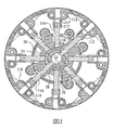
- the tyre building drum assembly comprises a rotatable hub assembly, a plurality of segments supported from the hub assembly for expanding and contracting movement between a collapsed position in which the tyre building drum has a relatively small overall diameter and an expanded position in which the segments define a cylindrical tyre building deck for the tyre building drum of larger overall diameter.
- the segments comprise first and second sets of segments, the first set 6 being disposed on a first outboard side of a transverse centre plane 10 of the tyre building drum and the second set 8 being disposed on a second inboard side of the transverse centre plane.
- the transverse centre plane is oriented normal to the rotational axis 12 of the drum.
- Each set of segments comprises alternating larger and smaller segments 14,16.
- the larger and smaller segments are mounted for simultaneous radial movement between the collapsed and expanded positions.
- Associated larger and smaller gap shields 18 are provided to close the axial gap between the first and second sets of segments.
- the side edges of the segments may be provided with a suitable, chamfered or rounded edge piece 20 forming a segmented ring to define the outermost edges of the outermost circumference or deck of the tyre building drum.
- a hub plate 22 is fixedly mounted to a hub shaft 24 for movement therewith.
- the hub plate may be fixed by any suitable means, such as in the illustrated embodiment by a hexagon socket countersunk head screw 25.
- an inboard hub 26 is mounted at the inboard end of the assembly.
- the inboard hub 26 is mounted on an adaptor 30.
- the adaptor 30 is mounted about the inboard end of the hub shaft 24 by way of an adaptor bush 32 and held in position by an end cap 34.
- the inboard hub 26 is mounted to the adaptor 30 by way of inboard hub bush 28 allowing axial movement of the inboard hub 26 with respect to the adaptor 30.
- the hub shaft is splined.
- the adaptor is also splined.
- the adaptor 30 is provided with a window 36.
- a spring means such as a helical spring 66 is located about the shank of the drive shaft 64 between the washer 76 and an end face of the recess 69.
- the shank of the drive shaft 64 is provided at an end remote from the head with an outer lock gear 68 secured thereto, for example by a riveted lock ring end cap 70.
- the outer lock gear 68 is secured to the shank of the drive shaft 64 against relative rotation with respect to the shank of the drive shaft 64.
- the outboard hub 40 is provided with a shaped recess within which the outer lock gear 68 may be received. Conveniently, the shaped recess is provided by an outer lock ring 71 provided in a shallow circular recess provided in the outboard hub.
- the outer lock ring 71 may conveniently be secured to the outboard hub 40 by a headed fastener such as a counter sunk screw 73.
- the spring means normally biases the drive shaft 64 such that the lock gear 68 is seated within the outer lock ring 71 thereby preventing rotation of the drive means.
- a bush or bearing 75 is conveniently provided within the outboard hub 40 about the shank of the drive shaft 64.
- the lock gear 68 By engaging the drive shaft 64 with a suitable, for preference dedicated, tool, the lock gear 68 may be moved axially and out of engagement with the outer lock ring 71. The tool may then be used to rotate the drive shaft, which due to engagement with the spur gear causes rotation of the spur gear 42 and the associated leadscrew gears 52. It will be noted that in the absence of the tool, the lock gear 68 acts to be seated within the outer lock ring 71 to prevent rotation of the drive means and so alteration of the axial position of the inboard and outboard hubs 26,40 (and their associated segment sets).
- the gap shields 18 are adapted to be mounted to the tyre building drum assembly by a series of alternating primary and secondary links 72,74.
- An outboard swing arm plate 76 is secured to the hub shaft 24 for rotation therewith between first and second thrust washers 78,79.
- a thrust needle roller and cage assembly 80 is located between third and fourth thrust washers 81,82.
- Adjacent and slightly further inboard a split housing washer 84 is seated in a groove in the hub shaft 24.
- the outboard swing arm plate 76 is located axially adjacent to the hub plate 22.
- a swing arm plate 86 is located over the adaptor 30. The swing arm plate 86 is splined to rotate with the adaptor 30.
- a lower shoulder of the swing arm plate 86 seats over the split housing washer.
- a radially extending flange 87 of the swing arm plate 86 extends over the thrust needle roller and cage assembly 80 and seats within a depression formed in the outboard swing arm plate 76.
- the primary and secondary links 72,74 are each pivotally connected at a first end about link pins 90 extending between the outboard swing arm plate 76 and the swing arm plate 86.
- a bush 91 is provided between the link 72,74 and the link pin 90 and thrust washers 92,93 between the link pin 91 and each of the outboard swing arm plate 76 and the swing arm plate 86.
- the primary and secondary links 72,74 are each pivotally connected at a second end by link pins 94 respectively to primary and secondary gap shield supports 96,98.
- one or more bushes 99 is provided between the link 72,74 and the gap shield support 96,98 and thrust washers 100,101 provided between the ends of the link pin and the respective gap shield support.
- the primary links 72 are provided with a curvature while the secondary links 74 are straight.
- Each of the gap shield supports is fixedly connected to its respective link pin by a suitable means such as hexagon socket set screw 102.
- Each segment comprises a pillar 110 and a body segment 112.
- Each pillar 110 is secured at a first end to a hub plate 22, 40.
- two of the door pillars 110 are secured through the inboard hub plate 26 and through a window 31 in the adaptor 30 to the hub shaft 24.
- the first ends of these two door pillars 110 are received in inboard drive keys 114 themselves secured to the hub shaft 24 for rotation therewith.
- the remaining pillars, including those at the outboard end, are retained in a respective hub plate 26,40 by suitable fasteners, such as hexagon socket set screws 116.
- Each body segment 112 is provided with an opening in the form of a blind bore lined with at least one bush 117 allowing the body segment 112 to be slidably mounted on a second end of the pillar 110.
- Each body segment 112 is provided with first and second bores 118,119 passing laterally of the blind bore.
- the first bore of an inboard body segment 112 is provided with a door rod 120.
- a first end of the door rod 120 is secured in the first bore.
- the second bore of the inboard body segment 112 is provided with a door tube 122.
- a first end of the door tube 122 is secured in the second bore.
- a second end of the door tube 122 is provided with one or more bushings or bearings 124.
- a complementary arrangement of door rod and door tube is provided in the outboard body segment 112, such that the door rod 120 of the inboard body segment penetrates the door tube 122 of the outboard body segment and that the door rod 112 of the outboard body segment penetrates the door tube 120 of the inboard body segment.
- the second end of each door tube is supported in bushes 126 provided in first and second through bores provided in the gap shield support 96,98.
- poppet caps 130 are provided to the outboard side of the hub plate 22.
- the poppets are adapted to be urged into corresponding recesses provided in the adjacent outboard swing arm plate 76 to retain the tyre building drum in the expanded position.
Landscapes
- Engineering & Computer Science (AREA)
- Manufacturing & Machinery (AREA)
- Mechanical Engineering (AREA)
- Tyre Moulding (AREA)
Claims (10)
- Dreh-REC-Reifenformungstrommel, umfassend eine Vielzahl von Segmenten (14, 16), die einen Außenumfang der Reifenformungstrommel definieren, wobei die Segmente in zwei Gruppen (6, 8) unterteilt sind, von denen eine jeder gegenüberliegenden Seite einer quer verlaufenden und senkrecht zur Drehachse (12) der Trommel angeordneten Mittelebene der Reifenformungstrommel zugeordnet ist, wobei die zwei Gruppen von Segmenten (14, 16) dazu geeignet sind, von einer Drehnabenbaugruppe zwischen einer kollabierten Position, in der eine gebildete Reifenkarkasse von der Reifenformungstrommel entfernt sein kann, und einer expandierten Position angetrieben zu werden, in der eine Reifenkarkasse an der Trommel gebildet sein kann, und jede Gruppe von Segmenten zur selektiven relativen Axialpositionierung angebracht ist, sowie außerhalb der Drehachse der Trommel angeordnete Mittel zum Einstellen der Gesamtarbeitsbreite der Trommel,
dadurch gekennzeichnet, dass eine Gruppe von Segmenten mit einer Innennabe (26) verbunden ist, die einer Seite der quer verlaufenden Mittelebene zugeordnet ist, und die andere Gruppe von Segmenten mit einer Außennabe (40) verbunden ist, die der gegenüberliegenden Seite der quer verlaufenden Mittelebene zugeordnet ist, wobei die Mittel außerhalb der Drehachse der Trommel angeordnet sind, um die Gesamtarbeitsbreite der Trommel einzustellen, und eine erste Gruppe von Innenleitspindeln (58), die mit der Innennabe (26) verbunden ist, und eine zweite Gruppe von Außenleitspindeln (54) umfassen, die mit der Außennabe (40) verbunden ist, wobei die Innen- und Außenleitspindeln (58, 54) jeweils dazu geeignet sind, sich derart relativ zueinander zu drehen, dass eine Drehung der Außenleitspindeln (58) eine Relativbewegung der Innenleitspindeln (54) bewirkt, und die Außenleitspindeln eine Einstellung der axialen Trennung der Innennabe (26) und der Außennabe (40) bewirken. - Reifenformungstrommel nach Anspruch 1, dadurch gekennzeichnet, dass ein erstes Ende jeder der Außenleitspindeln (58) dauerhaft mit einem Leitspindelgetriebe verbunden ist, das relativ zur Außennabe axial gelegen ist.
- Reifenformungstrommel nach Anspruch 1 oder 2, wobei ein zweites Ende jeder der Innenleitspindeln (54) fest mit der Innennabe (26) verbunden ist, um eine Drehung zwischen jeder der Innenleitspindeln und der Innennabe (26) zu verhindern.
- Reifenformungstrommel nach einem der Ansprüche 1 bis 3, dadurch gekennzeichnet, dass die Innenleitspindeln (54) und die Außenleitspindeln (58) miteinander in Gewindeeingriff sind.
- Reifenformungstrommel nach Anspruch 4, dadurch gekennzeichnet, dass die Außenleitspindeln (58) mit einem Gewinde versehen sind, das in eine Richtung dreht, und die Innenleitspindeln mit einem Gewinde versehen sind, das in die übliche Richtung dreht.
- Reifenformungstrommel nach Anspruch 4 oder 5, dadurch gekennzeichnet, dass die Außenleitspindeln (58) mit einem Gewinde einer ersten Steigung versehen sind und die Innenleitspindeln (54) mit einem Gewinde einer abweichenden Steigung versehen sind.
- Reifenformungstrommel nach Anspruch 6, dadurch gekennzeichnet, dass das Steigungsverhältnis des Gewindes jeder Innenleitspindel (54) und jeder Außenleitspindel (58) 2:1 ist.
- Reifenformungstrommel nach einem der Ansprüche 2 bis 7, dadurch gekennzeichnet, dass die Leitspindelgetriebe jeder der Außenleitspindeln von einem gemeinsamen Stirnradgetriebe (42) angetrieben werden.
- Reifenformungstrommel nach Anspruch 8, dadurch gekennzeichnet, dass ein Antriebsmechanismus vorgesehen ist, um das Stirnradgetriebe (42) selektiv anzutreiben.
- Reifenformungstrommel nach irgendeinem vorangegangenen Anspruch, dadurch gekennzeichnet, dass die Gruppen von Segmenten (6, 8) auf jeder Seite der quer verlaufenden Mittelebene mittels sich gegenseitig durchdringender Stangen und Hülsen in Ausrichtung gehalten werden.
Applications Claiming Priority (2)
| Application Number | Priority Date | Filing Date | Title |
|---|---|---|---|
| GBGB0603700.6A GB0603700D0 (en) | 2006-02-24 | 2006-02-24 | Expandable mandrel having adjustable width |
| PCT/GB2007/000625 WO2007096629A1 (en) | 2006-02-24 | 2007-02-23 | Expandable mandrel havin adjustable width |
Publications (2)
| Publication Number | Publication Date |
|---|---|
| EP1993818A1 EP1993818A1 (de) | 2008-11-26 |
| EP1993818B1 true EP1993818B1 (de) | 2012-02-01 |
Family
ID=36178674
Family Applications (1)
| Application Number | Title | Priority Date | Filing Date |
|---|---|---|---|
| EP07705256A Ceased EP1993818B1 (de) | 2006-02-24 | 2007-02-23 | Spreizbarer dorn mit verstellbarer breite |
Country Status (5)
| Country | Link |
|---|---|
| US (1) | US8272417B2 (de) |
| EP (1) | EP1993818B1 (de) |
| CN (1) | CN101400507A (de) |
| GB (1) | GB0603700D0 (de) |
| WO (1) | WO2007096629A1 (de) |
Families Citing this family (12)
| Publication number | Priority date | Publication date | Assignee | Title |
|---|---|---|---|---|
| GB0506363D0 (en) | 2005-03-30 | 2005-05-04 | Wyko Equip | Tyre building drum |
| US8899292B2 (en) | 2010-10-14 | 2014-12-02 | Davian Enterprises, LLC | Fully supported expandable deck |
| US10189221B2 (en) | 2012-08-10 | 2019-01-29 | Davian Enterprises, LLC | Transfer ring shoe and transfer ring having varied shoe profile |
| RU2659249C2 (ru) | 2013-06-07 | 2018-06-29 | Дейвиан Энтерпрайзиз, Ллк | Шиносборочный барабан с увеличенным диапазоном перемещения |
| EP3102400A4 (de) | 2014-02-07 | 2017-10-18 | Davian Enterprises, LLC | Erweiterbare trommel mit ungleichmässigen segmentprofilen |
| CN106003777B (zh) * | 2016-07-07 | 2018-02-13 | 萨驰华辰机械(苏州)有限公司 | 轮胎成型鼓 |
| US11358356B2 (en) | 2018-09-27 | 2022-06-14 | Davian Enterprises, LLC | Transfer ring with block and rail system |
| US11548251B2 (en) | 2019-01-28 | 2023-01-10 | Davian Enterprises, LLC | Expandable belt and tread drum with reverse offset fingers |
| IT201900023616A1 (it) | 2019-12-11 | 2021-06-11 | Pirelli | Tamburo di formatura per la produzione di pneumatici per ruote di veicoli e metodo per controllare la geometria di un tamburo di formatura per la produzione di pneumatici per ruote di veicoli |
| EP4139120B1 (de) | 2020-04-22 | 2025-08-06 | William A. Jones | Schulteranordnung für reifenaufbaumaschine |
| WO2021243326A1 (en) | 2020-05-29 | 2021-12-02 | Mccleery Kenneth | Transfer ring shoe and transfer ring with reduced air entrapment features |
| US11993043B2 (en) | 2020-12-03 | 2024-05-28 | Davian Enterprises, LLC | Expandable belt and tread drum with magnetic deck fixing |
Family Cites Families (10)
| Publication number | Priority date | Publication date | Assignee | Title |
|---|---|---|---|---|
| US3695974A (en) | 1970-03-09 | 1972-10-03 | Gen Tire & Rubber Co | Tire building drum |
| DE2630893A1 (de) * | 1976-07-09 | 1978-01-12 | Metzeler Kautschuk | Axial verstellbare reifenaufbautrommel |
| US4155796A (en) * | 1978-06-28 | 1979-05-22 | The Goodyear Tire & Rubber Company | Single section tire building drum |
| JPS59202837A (ja) * | 1983-05-02 | 1984-11-16 | Bridgestone Corp | タイヤ成形装置 |
| JPS60196330A (ja) | 1984-03-19 | 1985-10-04 | Bridgestone Corp | タイヤ成形ドラム |
| JPS61297127A (ja) | 1985-06-26 | 1986-12-27 | Yokohama Rubber Co Ltd:The | タイヤ成形機に於けるドラム装置 |
| US5354405A (en) * | 1993-11-18 | 1994-10-11 | Wyko, Inc. | Bead lock drum for use in the manufacture of vehicle tires |
| US6673183B2 (en) * | 2001-07-31 | 2004-01-06 | Wyko, Inc. | Method and apparatus for tire carcass positioning on a drum |
| US6827119B2 (en) * | 2002-03-11 | 2004-12-07 | The Goodyear Tire & Rubber Company | Radially expansible tire assembly drum and method for forming tires |
| WO2004060644A1 (en) * | 2002-12-30 | 2004-07-22 | Societe De Technologie Michelin | Tire building apparatus and assembly process |
-
2006
- 2006-02-24 GB GBGB0603700.6A patent/GB0603700D0/en not_active Ceased
-
2007
- 2007-02-23 EP EP07705256A patent/EP1993818B1/de not_active Ceased
- 2007-02-23 CN CNA2007800063070A patent/CN101400507A/zh active Pending
- 2007-02-23 US US12/280,331 patent/US8272417B2/en active Active
- 2007-02-23 WO PCT/GB2007/000625 patent/WO2007096629A1/en not_active Ceased
Also Published As
| Publication number | Publication date |
|---|---|
| WO2007096629A1 (en) | 2007-08-30 |
| GB0603700D0 (en) | 2006-04-05 |
| US8272417B2 (en) | 2012-09-25 |
| US20090242138A1 (en) | 2009-10-01 |
| EP1993818A1 (de) | 2008-11-26 |
| CN101400507A (zh) | 2009-04-01 |
Similar Documents
| Publication | Publication Date | Title |
|---|---|---|
| EP1993818B1 (de) | Spreizbarer dorn mit verstellbarer breite | |
| DE69526529T2 (de) | Verbesserte Trommel zum Herstellen von Gürteln und Laufflächen für eine Reifenaufbaumaschine | |
| EP3507526B1 (de) | Planetengetriebe | |
| DE69710888T2 (de) | Aufbautrommel zur luftreifenherstellung | |
| EP1286827B1 (de) | Spreizbarer dorn mit einstellbarer breite | |
| DE102007057484B3 (de) | Reifenmontiermaschine | |
| DE112013003689T5 (de) | Exzentrisch schwingende Vorrichtung | |
| DE102015101509A1 (de) | Rollengewindetrieb, Verfahren und Werkzeug zur Montage der Rollen in einem solchen Rollengewindetrieb | |
| DE102009030614A1 (de) | Freilauf-Käfigring mit Fliehkraftabhebung | |
| DE60218095T2 (de) | Trommel zum Aufbau einer Reifenkarkasse und dieselbe enthaltende Einrichtung | |
| EP2126537B1 (de) | Spannvorrichtung | |
| DE112011105959T5 (de) | Rollengewindetrieb | |
| EP2595772B1 (de) | Strukturierte gleitfläche einer lagerschale | |
| DE202014104688U1 (de) | Rotationswerkzeug | |
| CN110695922B (zh) | 一种精密零件上的空心定位销拆卸用作业工装 | |
| EP2112260B1 (de) | Rundstrickmaschine mit einer drehbar gelagerten Rippscheibe | |
| EP2577101A1 (de) | Mutter eines planetenwälzgewindetriebes und verfahren zur herstellung einer solchen mutter | |
| WO2021052526A1 (de) | Planetenwälzgewindetrieb | |
| DE102017113396A1 (de) | Arbeitsspindel mit Radialklemmeinrichtung | |
| EP3515644B1 (de) | Schneidexzenterantrieb mit variablem hub | |
| EP3168497B1 (de) | Getriebe und verwendung eines getriebes | |
| CN101954565A (zh) | 翻边轴承的更换工艺 | |
| DE112023000137T5 (de) | Werkstückhaltevorrichtung | |
| CN104439778B (zh) | 零件开口的撑开工件 | |
| US20150165501A1 (en) | Thread rolling head |
Legal Events
| Date | Code | Title | Description |
|---|---|---|---|
| PUAI | Public reference made under article 153(3) epc to a published international application that has entered the european phase |
Free format text: ORIGINAL CODE: 0009012 |
|
| 17P | Request for examination filed |
Effective date: 20080922 |
|
| AK | Designated contracting states |
Kind code of ref document: A1 Designated state(s): DE GB IT NL |
|
| 17Q | First examination report despatched |
Effective date: 20081205 |
|
| DAX | Request for extension of the european patent (deleted) | ||
| RBV | Designated contracting states (corrected) |
Designated state(s): DE GB IT NL |
|
| GRAP | Despatch of communication of intention to grant a patent |
Free format text: ORIGINAL CODE: EPIDOSNIGR1 |
|
| GRAS | Grant fee paid |
Free format text: ORIGINAL CODE: EPIDOSNIGR3 |
|
| RAP1 | Party data changed (applicant data changed or rights of an application transferred) |
Owner name: WYKO TIRE TECHNOLOGY LIMITED |
|
| GRAA | (expected) grant |
Free format text: ORIGINAL CODE: 0009210 |
|
| AK | Designated contracting states |
Kind code of ref document: B1 Designated state(s): DE GB IT NL |
|
| REG | Reference to a national code |
Ref country code: GB Ref legal event code: FG4D |
|
| REG | Reference to a national code |
Ref country code: DE Ref legal event code: R096 Ref document number: 602007020405 Country of ref document: DE Effective date: 20120329 |
|
| REG | Reference to a national code |
Ref country code: NL Ref legal event code: VDEP Effective date: 20120201 |
|
| PG25 | Lapsed in a contracting state [announced via postgrant information from national office to epo] |
Ref country code: NL Free format text: LAPSE BECAUSE OF FAILURE TO SUBMIT A TRANSLATION OF THE DESCRIPTION OR TO PAY THE FEE WITHIN THE PRESCRIBED TIME-LIMIT Effective date: 20120201 |
|
| PG25 | Lapsed in a contracting state [announced via postgrant information from national office to epo] |
Ref country code: IT Free format text: LAPSE BECAUSE OF FAILURE TO SUBMIT A TRANSLATION OF THE DESCRIPTION OR TO PAY THE FEE WITHIN THE PRESCRIBED TIME-LIMIT Effective date: 20120201 |
|
| PLBE | No opposition filed within time limit |
Free format text: ORIGINAL CODE: 0009261 |
|
| STAA | Information on the status of an ep patent application or granted ep patent |
Free format text: STATUS: NO OPPOSITION FILED WITHIN TIME LIMIT |
|
| 26N | No opposition filed |
Effective date: 20121105 |
|
| REG | Reference to a national code |
Ref country code: DE Ref legal event code: R097 Ref document number: 602007020405 Country of ref document: DE Effective date: 20121105 |
|
| PGFP | Annual fee paid to national office [announced via postgrant information from national office to epo] |
Ref country code: GB Payment date: 20200212 Year of fee payment: 14 |
|
| GBPC | Gb: european patent ceased through non-payment of renewal fee |
Effective date: 20210223 |
|
| PG25 | Lapsed in a contracting state [announced via postgrant information from national office to epo] |
Ref country code: GB Free format text: LAPSE BECAUSE OF NON-PAYMENT OF DUE FEES Effective date: 20210223 |
|
| PGFP | Annual fee paid to national office [announced via postgrant information from national office to epo] |
Ref country code: DE Payment date: 20240226 Year of fee payment: 18 |
|
| REG | Reference to a national code |
Ref country code: DE Ref legal event code: R119 Ref document number: 602007020405 Country of ref document: DE |
|
| PG25 | Lapsed in a contracting state [announced via postgrant information from national office to epo] |
Ref country code: DE Free format text: LAPSE BECAUSE OF NON-PAYMENT OF DUE FEES Effective date: 20250902 |