EP1993787B1 - Quick-change holder for screwdriver inserts - Google Patents
Quick-change holder for screwdriver inserts Download PDFInfo
- Publication number
- EP1993787B1 EP1993787B1 EP07701907A EP07701907A EP1993787B1 EP 1993787 B1 EP1993787 B1 EP 1993787B1 EP 07701907 A EP07701907 A EP 07701907A EP 07701907 A EP07701907 A EP 07701907A EP 1993787 B1 EP1993787 B1 EP 1993787B1
- Authority
- EP
- European Patent Office
- Prior art keywords
- bit
- quick
- magnet
- locking
- change holder
- Prior art date
- Legal status (The legal status is an assumption and is not a legal conclusion. Google has not performed a legal analysis and makes no representation as to the accuracy of the status listed.)
- Not-in-force
Links
Images


Classifications
-
- B—PERFORMING OPERATIONS; TRANSPORTING
- B25—HAND TOOLS; PORTABLE POWER-DRIVEN TOOLS; MANIPULATORS
- B25B—TOOLS OR BENCH DEVICES NOT OTHERWISE PROVIDED FOR, FOR FASTENING, CONNECTING, DISENGAGING OR HOLDING
- B25B23/00—Details of, or accessories for, spanners, wrenches, screwdrivers
- B25B23/0007—Connections or joints between tool parts
- B25B23/0035—Connection means between socket or screwdriver bit and tool
-
- B—PERFORMING OPERATIONS; TRANSPORTING
- B23—MACHINE TOOLS; METAL-WORKING NOT OTHERWISE PROVIDED FOR
- B23B—TURNING; BORING
- B23B31/00—Chucks; Expansion mandrels; Adaptations thereof for remote control
- B23B31/02—Chucks
- B23B31/10—Chucks characterised by the retaining or gripping devices or their immediate operating means
- B23B31/107—Retention by laterally-acting detents, e.g. pins, screws, wedges; Retention by loose elements, e.g. balls
- B23B31/1071—Retention by balls
-
- B—PERFORMING OPERATIONS; TRANSPORTING
- B25—HAND TOOLS; PORTABLE POWER-DRIVEN TOOLS; MANIPULATORS
- B25B—TOOLS OR BENCH DEVICES NOT OTHERWISE PROVIDED FOR, FOR FASTENING, CONNECTING, DISENGAGING OR HOLDING
- B25B15/00—Screwdrivers
- B25B15/001—Screwdrivers characterised by material or shape of the tool bit
-
- B—PERFORMING OPERATIONS; TRANSPORTING
- B25—HAND TOOLS; PORTABLE POWER-DRIVEN TOOLS; MANIPULATORS
- B25B—TOOLS OR BENCH DEVICES NOT OTHERWISE PROVIDED FOR, FOR FASTENING, CONNECTING, DISENGAGING OR HOLDING
- B25B23/00—Details of, or accessories for, spanners, wrenches, screwdrivers
- B25B23/02—Arrangements for handling screws or nuts
- B25B23/08—Arrangements for handling screws or nuts for holding or positioning screw or nut prior to or during its rotation
- B25B23/12—Arrangements for handling screws or nuts for holding or positioning screw or nut prior to or during its rotation using magnetic means
Definitions
- the present invention relates to a quick-change holder for screwdriver bits according to the preamble of claim 1, which is known from the document US 2001/043841 A is known.
- Screwdriver bits also known as screwdriver bits or simply bits, are known in the art. Such bits are widely used by commercial and private users as interchangeable tips of electrically powered drill and screwdrivers. In recent years, cordless drills and screwdrivers have become popular in the commercial field, as well as in home improvement, so that drilling and screwing with the help of screwdriver bits can be carried out independently of the network in all locations. When working on scaffolding, ladders or in hard-to-reach places, it is of particular importance that the bits can be easily replaced, preferably with one hand, and that a single screwdriver, or a single quick-change bracket with as many different types of bits can be used.
- the screwdriver bits or bits are torque-fitted into a holder, which is formed either on the work spindle of the screwing or in a holder part, which is inserted into a chuck of the screwing.
- the torque-locking driving connection between the holder and the screwdriver bit is usually effected by a hexagon socket receiving the holder and a corresponding hexagon of the screwdriver bit. From the company Fein But also inserts with a participatedflachkant are known, which also ensure a torque-locking driving connection in a corresponding receptacle.
- the external hexagon has a recess of shallow depth, which only penetrates into the edges of the external hexagon.
- the screwdriver bit is held in the receptacle by a spring ring mounted in the hexagon socket of the receptacle, which engages with inserted screwdriver bit into the groove.
- the hexagon socket of the screwdriver bit has a deep groove with a large profile radius.
- a detent ball engages radially into this groove.
- the detent ball is held by an axially spring-loaded sleeve with inner cone in the groove. By moving the sleeve against the spring load of the inner cone releases the detent ball, so that the screwdriver bit can be removed.
- the DE-U-20201021 proposes, therefore, to provide a holder for screwdriver bits, which can accommodate both screwdriver bits Form C and screwdriver bits Form E according to DIN 3126.
- a locking element in the form of a ball is mounted in the hexagon socket of the drive-side recording of the holder, which is formed according to the axial position and the radial depth of the recess of the hexagon of a screwdriver bit of form C according to DIN 3126.
- another ball of elastomeric material is pressed, which axially resiliently supports the screwdriver bit used in the recording.
- the elastomeric elements are designed so that their axial bias supports the removal of a bit, so it can easily lead to that by the additional pressure of the Elastomerelements the bit jumps out of the receiving opening very quickly and the user must catch him sent.
- less skilled users easily lose screwdriver bits from inaccessible areas of the workplace. In this way, a lot of time and labor can be wasted in searching and retrieving.
- a protruding screwdriver bit due to its hardness and weight not insignificant risk of injury.
- another disadvantage is that the elastomeric elements have only a limited life.
- German utility model DE 20303079 The problem of the uncontrolled jumping out of the bits was recognized and it was also recognized that a protruding screwdriver bit due to its hardness and its weight represents a significant risk of injury on construction sites. It is therefore in the DE 20303079 a chuck for tool inserts, in particular a chuck for screwdriver bits proposed, in which two permanent magnets are arranged in the sleeve body. The poles of the same direction face each other, so that the two permanent magnets repel each other. The replacement of the springs by repelling magnets to reduce the risk that the bits when removing too quickly jump out of the chuck.
- the US 2001/0043841 shows a bit holder with a holding mechanism for holding a bit and an ejection means for facilitating the bit replacement, the ejection means having a shuttle which is acted upon by a compression spring and partially releases the bit upon release of a ball lock from the holding mechanism.
- the holding mechanism comprises a spherical Locking element which is pressed by an elastic O-ring in the circumferential groove of the type E bits used.
- a major disadvantage of in the US 2001/0043841 proposed bit holder is that this tends to jamming by the application of force to the ejection means and the holding mechanism, especially with frequent bit change.
- the holding mechanism is designed so that preferably only bits of type E can be held.
- An essential idea of the invention is to provide in the bit holder means for locking the first opening side mounted magnet in a rear holding position, which allow the bit to be inserted with one hand, without a simultaneous manual operation of an outer sleeve is necessary.
- the locking of the magnet in the holding position brings significant benefits.
- the latching element for the bit is greatly relieved, since the axial force of the ejection mechanism is no longer loaded on the bit or the latching element and the bit is also held by the magnet to the other can use bits of different standards, since at a selected axial position of the locking element, the sliding movable mounting of the first magnet allows the insertion of erbits different shapes and standards and these each magnetkraftbeetzschlagt supported in the axial direction.
- bits of various shapes in the inventive quick-change holder can be safely held without disturbing axial play.
- FIG. 1 is a longitudinal section through a quick-change holder 1 for bits shown, which is fixedly mounted on a shaft S of an electrically operated screwdriver or a drill not shown from the machine housing, only a front cover F is shown having a breakthrough D for receiving a on the shaft S. fastened drive-side end 21 of the bit holder 2 has.
- the quick change holder according to the invention instead of on the shaft S of a machine on a hexagon or a flat edge for releasable support in a suitable chuck a drill or a screwdriver can be secured against rotation.
- quick-change holders 1 are understood to mean both those for a fixed machine assembly and those in the form of a change-over holder. It will be apparent to those skilled in the art that how and how the novel teachings of the present invention can be applied to both types without limitation.
- the bit holder 2 is in the FIGS. 2a to 2f shown in detail. It consists essentially of a hollow cylinder having a cylindrical bore 22 for attachment to a driven shaft S of a drill at a rear drive end.
- the front portion of the bit holder is provided with a hexagon socket 23 for torque-locking recording of the bits. Hexagon socket 23 and cylindrical bore 22 overlap in a central region 24 of the bit holder 2.
- the diameter of the bore 22 is matched to the size of the hexagon socket, that at the front end face of the overlap region six rearwardly directed abutment surfaces 25 are formed.
- In the overlap region passes through a radial bore 26 for receiving the locking element 6, which is preferably designed as a ball, the wall of the bit holder 2.
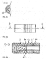
- In the front region of the hexagon socket is a Tangentialnut 27 cut so deep into the wall that a window 27 'for receiving a Locking element 9 is broken in the hexagon socket 23.
- a first permanent magnet 3 also called ejection magnet
- the first magnet 3 is pressed into a cylindrical seat 31, molded or cast, which is provided on an outer side with a locking groove 32.
- the seat is preferably made of stainless steel or plastic, so that the operations for attaching the groove 32 are easily performed can, the life is high and the magnetic effect is not significantly attenuated.
- the locking groove 32 advantageously extends approximately parallel to the longitudinal axis of the magnet 3 and is adapted in the illustrated embodiment to a spherical locking element 6.
- the groove 32 has a constant radius R, which substantially corresponds to the radius of the locking ball 6, wherein the depth of the groove 32 from the front end 34 to the rear end 35 decreases steadily.
- the pitch ⁇ at the apex of the groove is, according to a preferred embodiment, 7 °.
- the function of the locking groove 32 illustrates the cross section of FIG. 1 , A spherical locking element 6 is inserted into the radial bore 26 in the wall of the bit holder 2.
- An ejector sleeve 5 is mounted coaxially on the bit holder 2, and limits axially displaceable.
- the substantially circular cylindrical ejector sleeve 5 is in the FIG. 3 shown in more detail. On the outside, it is provided in a central region with three circumferential webs 51, which facilitate the gripping and axial displacement of the sleeve 5.
- the webs 51 may also be replaced by a knurled area or a grippy elastomer insert. More important for the function is the design of the inner wall of the sleeve 5.
- the inner diameter of the sleeve 52 widens via a conical section 53 to a circumferential receiving space 54 for a latching or clamping element 9, the function of which will be described in more detail below.
- the rear end of the receiving space 54 is formed by a step at which the inner diameter is reduced again, so that the sleeve 52 in turn sits with little play on the receptacle 2.
- This rear portion 55 extends to the drive-side end of the sleeve and is interrupted only by a circumferential recess 56 which has approximately the same radius as the locking ball 6.
- the rear end of the sleeve forms an inwardly directed rib 57, which in the assembled state, as in the FIG. 1 is shown, a spring 8 serves as an abutment.
- the spring 8 pushes the ejector sleeve 5 to the rear until the locking ball 6 can engage with its radially outward directed portion into the recess 56. On the inward side, the ball engages in the locking groove 32 a.
- the front magnet 3 has a pole of the same direction to the rear magnet 4, so that repel the two permanent magnets. Since the rear magnet 4 rests in a receptacle 41 axially immovable directly on the shaft S, the front magnet 3 is pressed in the direction of the receiving opening 28.
- the locking ball 6 is pressed by the forward movement of the magnet 3 and the decreasing depth of the locking groove 52 outwardly into the recess 56 of the sleeve 5, the diameter of the locking ball 6 is so on the diameter of the cylindrical seat 31 of the ejection magnet 3, the wall thickness of the recording 2 adapted in the transition region and the inner diameter of the sleeve in the puncture area that in the receptive delivery, as shown in the FIG. 1 is shown, the ejection magnet 3 and the sleeve 5 are held in a forward position. In this position, the front end side of the magnet 3 and the magnetic seat 31 abuts against the stop surfaces 25. At the same time, the receiving space 54 of the sleeve 5 is located above the tangential groove 27, so that the latching element 9 essentially releases the window 27 '.
- the spring 8 pushes the sleeve 5 backwards and the ball 6 is locked in the radially inner position.
- the magnet 3 is thereby held in a rear position and can not be moved forward despite the rejection by the second magnet 4.
- the inner cone 53 simultaneously pushes the locking element 9 inwards, so that a part of the locking element protrudes through the window 27 'in the hexagon socket and engages there into the respective recess of the hexagon of the inserted bit.
- the bit is not acted upon in the inserted state with the effective force during ejection
- the axially acting repulsive magnetic force is received with the bit inserted by the locking element 6, so that the Rastemaniente 9 with much play in the recess of Hexagon of the bits can engage and are not loaded.
- the bits are usually made of metallic materials and alloys, which are additionally held by the attraction of the magnet 3 in the receptacle 2, can be dispensed with entirely advantageous locking embodiments 9 in advantageous embodiments. Falling out of the bits used from the bit holder 2 is prevented solely by the attraction of the first magnet 3.
- the adaptation of the axial position of the locking means 9 on the standardized punctures in the bit does not play a significant role and the inventive bit holder can be advantageously with a variety Use bit types of different standards.
- a spacer ring 60 is mounted between the front magnet 3 'and the inserted bit B in the interior of the bit holder 2'.
- the spacer ring 60 with its free central region 61 makes it possible to insert so-called double bits, since in each case the unused working tip is partially inserted into the free space 61 can protrude.
- the spacer ring 60 can be additionally equipped with a stroke limiter 62 which comprises a radially outwardly projecting pin which engages in a corresponding slot in the inner wall of the receptacle 2 '. This makes it possible to limit the axial forward ejection movement driven by the magnetic forces to a few millimeters.
- a spacer ring 60 can also be used in bit holders with magnetically assisted ejection and conventional Arretieruhgskarn 63 for engaging in the respective grooves of the bits.
- FIG. 7 A further embodiment of a bit holder according to the present invention is shown, which is also particularly suitable for receiving double bits B '.
- bit holder 80 according to this embodiment, the function of the spacer ring in the Magnetic seat integrated.
- Figure 7a shows that on the front side of the magnetic seat 81, a spacer ring 82 is integrally formed, which in turn has on its front a central conical receiving opening 83.
- This free central area 83 makes it possible to use so-called double-bits B 'since the working tip which is not required in each case can partially protrude into the free interior space 83, as shown in FIG FIG. 7b is shown.
- the cone is shaped so that the tip of the bit is kept spaced from the ejection magnet 3 'to prevent damage to the magnet 3' by the bit.
- the locking groove 32 ' is designed in a rear region analogous to the previously described locking groove 32. That it rises again in the region of the spacer ring 82 is primarily due to manufacturing technology, but not essential for the function, since the locking ball 6 'does not interact with this region of the groove 32'.
- the design and function of the parts of the device that are essential for locking are analogous to the quick change holder 1 described above.
- FIG. 7c illustrates that the wall of the bit holder 2 'is pierced by two radial bores 29', 29 " FIG. 7c is intended to illustrate that the two radial bores and thus the two locking balls 9 ', 9 “offset by 60 ° to each other on two adjacent side surfaces of the hexagon socket of the receptacle 2' are arranged FIGS. 7a and 7b make it clear that the two radial bores 29 ', 29 "for radially displaceable receiving the detent balls 9', 9" also axially spaced from each other.
- Such a placement of the detent elements 9 ', 9 "ensures that all common types of bits can be secured in the inserted position against falling out.
- the two inner cones 53 'and 53" press the detent elements 9' and 9 "inward, so that in each case at least one radially inwardly directed part of the respective latching element 9 'or 9" protrudes into the hexagon socket and There can intervene in the respective recess of the hexagon of the inserted bit.
- the height h of the magnetic seat 81 including the integrated spacer ring 82 is 8 mm, and the axial travel g which the magnet can travel in the receptacle 2 'is limited to 2 mm.
- the bits in the inserted state are not acted upon by the effective force during ejection.
- the axially acting repulsive magnetic force is in turn received in the inserted bit despite two locking elements 9 'and 9 "in turn by the locking element 6'.
- the in the FIGS. 9a to 9d shown quick-change holder 101 is another embodiment of the invention.
- the Bitaufahme 102 consists essentially of a hollow cylinder, which is completed at its rear end by an inserted into the hollow cylinder and fx
- S ' for example, a drill.
- this shaft S ' is represented by a hexagonal pin.
- this hexagonal pin is approximately identical to the dimension of the hexagon of the standardized screw bits, so that the hollow cylinder in its interior preferably a constant Has hexagonal contour over its entire length and the bits can be recorded torque-locking.
- a magnetic seat 131 is movably mounted with a locking groove 132 mounted on its front outer side with a pitch ⁇ '.
- this magnetic seat 131 has an outer contour in the form of a hexagon.
- the magnetic seat 131 has on its front side a conical bore, which essentially corresponds in function and dimensioning to the spacer ring 60, 82, so that so-called double bits can be easily picked up.
- a magnet 103 is preferably mounted, which holds a bit in its ejection. This magnet 103 substantially corresponds in its function and dimensioning to the magnet 3.
- the ejection force is not generated by way of a second magnet, but conventionally by means of an ejection spring 110, which pushes the magnetic seat forward.
- a locking element 106 preferably in the form of a ball, prevents, in cooperation with the locking groove 132, that the force required for the ejection permanently acts on the bit and thus on the locking element 109, which is mounted displaceably in a radial bore 129.
- two locking elements 109 are offset by 60 ° in the bit holder 102 arranged so that they act on the edges of the hexagon, or on the introduced therein recesses.
- the locking elements but also as in FIG. 7c shown acting on the side surfaces of the hexagon.
- the ejector sleeve 105 is pressed against the spring force of the spring 108 to the front, so that the locking member 106 can escape into the recess 156 of the ejector sleeve 105. At the same time allows this pushing the ejector sleeve 105 forward that the locking elements 109 can move into the receiving space 154 of the ejection sleeve 105 and thus released the bit for removal and is held only by the magnet 103.
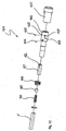
- FIG. 10 shows in an exploded view, the individual parts of Schnell conference hatcht ceremonies 101 according FIG. 9a , Clearly visible together with the FIG. 9b the fact that all the items except the locking and latching elements 106, 109 are mountable from one direction, namely from behind, which simplifies the manufacture and also allows substantial savings on the cost side
- FIGS. 11a to 11e show different variants of known and commercially available bits, which could be absorbed by the inventive quick-change holder.
- FIG. 11 a is for example a bit according to DIN 3126 C
- FIG. 11b One bit according to DIN 3126 E It goes without saying that the teaching of the invention is not limited to these variants shown.
Abstract
Description
Die vorliegende Erfindung betrifft einen Schnellwechselhalter für Schraubendrehereinsätze gemäss Oberbegriff des Anspruchs 1, der aus dem Dokument
Aus dem Stand der Technik sind Schraubendrehereinsätze, die auch als SchraubendreherBits oder einfach als Bits bezeichnet werden bekannt. Solche Bits sind bei gewerblichen und privaten Anwendern als auswechselbare Arbeitsspitzen von elektrisch angetriebenen Bohrmaschirlen und Schraubendrehern weit verbreitet In den letzten Jahren haben sich im gewerblichen Bereich, aber auch bei Heimwerkern akkugetriebene Bohrmaschinen und Schraubendreher durchgesetzt, so dass Bohr und Schraubarbeiten mit Hilfe der Schraubendreher-Bits an allen Orten netzunabhängig durchgeführt werden können. Bei Arbeiten auf Gerüsten, Leitern oder an schwer zugänglichen Stellen ist es von besonderer Bedeutung, dass sich die Bits einfach, vorzugsweise mit einer Hand auswechseln lassen und dass ein einziger Schraubendreher, respektive eine einzige Schnellwechselhalterung mit möglichst vielen verschiedenen Typen von Bits verwendet werden kann.Screwdriver bits, also known as screwdriver bits or simply bits, are known in the art. Such bits are widely used by commercial and private users as interchangeable tips of electrically powered drill and screwdrivers. In recent years, cordless drills and screwdrivers have become popular in the commercial field, as well as in home improvement, so that drilling and screwing with the help of screwdriver bits can be carried out independently of the network in all locations. When working on scaffolding, ladders or in hard-to-reach places, it is of particular importance that the bits can be easily replaced, preferably with one hand, and that a single screwdriver, or a single quick-change bracket with as many different types of bits can be used.
Es ist bekannt und zum Beispiel in der
Zum lösbaren Einrasten von Schraubendrehereinsätzen in der Halterung sind insbesondere zwei Sechskant-Mitnahme-Verbindungen gebräuchlich, die gemäß DIN 3126 genormt sind.For releasable engagement of screwdriver bits in the holder in particular two hexagonal driving connections are common, which are standardized according to DIN 3126.
In der Form C der DIN 3126 weist der Aussensechskant einen Einstich geringer Tiefe auf, der nur in die Kanten des Aussensechskants eindringt. Der Schraubendrehereinsatz wird in der Aufnahme durch einen in dem Innensechskant der Aufnahme der Halterung gelagerten Sprengring, der bei eingesetztem Schraubendrehereinsatz in den Einstich eingreift gehalten.In form C of DIN 3126, the external hexagon has a recess of shallow depth, which only penetrates into the edges of the external hexagon. The screwdriver bit is held in the receptacle by a spring ring mounted in the hexagon socket of the receptacle, which engages with inserted screwdriver bit into the groove.
In der Form E der DIN 3126 weist der Aussensechskant des Schraubendrehereinsatzes einen tiefen Einstich mit einem großen Profilradius auf. Um den Schraubendrehereinsatz in der Aufnahme der Halterung zu halten, greift eine Rastkugel radial in diesen Einstich ein. Die Rastkugel wird durch eine axial federbelastete Hülse mit Innenkonus in dem Einstich gehalten. Durch Verschieben der Hülse gegen die Federbelastung gibt der Innenkonus die Rastkugel frei, so dass der Schraubendrehereinsatz entnommen werden kann.In the form E of DIN 3126, the hexagon socket of the screwdriver bit has a deep groove with a large profile radius. To hold the screwdriver bit in the receptacle of the holder, a detent ball engages radially into this groove. The detent ball is held by an axially spring-loaded sleeve with inner cone in the groove. By moving the sleeve against the spring load of the inner cone releases the detent ball, so that the screwdriver bit can be removed.
In der
Die
Diese Nachteile sind auch von anderen Bithaltern bekannt, bei denen zwischen dem geschlossenen Ende eines Hülsenkörpers und dem aufgenommenen Bit eine Feder angeordnet ist, die durch Einführen des Schraubendrehereinsatzes in die Öffnung unter Spannung gesetzt wird. Durch den Druck, den eine äußere Spannhülse auf Arretierkugeln ausübt, wird der Schraubendrehereinsatz in Position gehalten. Beim Auswechseln des Werkzeugeinsatzes gelben die Arretierkugeln den Bit frei und die Kraft der vorgespannten Feder drückt den Bit automatisch aus der Öffnung heraus.These disadvantages are also known from other bit holders, in which a spring is arranged between the closed end of a sleeve body and the bit received, which is put under tension by inserting the screwdriver bit into the opening. Due to the pressure exerted by an outer clamping sleeve on locking balls, the screwdriver bit is held in position. When replacing the tool bit, the locking balls free the bit and the force of the preloaded spring automatically pushes the bit out of the hole.
Im deutschen Gebrauchsmuster
Die
Es ist daher die Aufgabe der vorliegenden Erfindung eine neue Schnellwechselhalterung für Schraubendrehereinsätze zur Verfügung zu stellen, die die oben genannten Nachteile nicht aufweist. Die Schraubendrehereinsätze sollen schnell und sicher mit einer Hand eingesetzt und entnommen werden können, ohne dass die Gefahr besteht, dass sie herunterfallen. Zudem sollen Einsätze verschiedener Grössen und Bauart mit der Vorrichtung gemäss der vorliegenden Erfindung eingesetzt werden können. Die technische Lehre der Erfindung erlaubt es dem Fachmann, einen Schnellwechselhalter zu gestalten in dem zwei oder mehr Typen von Bits aus der folgenden Gruppe gehalten werden können: Form C und E gemäß DIN 3126, Bits gemäss der japanischen Norm oder so genannte Japanbits wie sie von der Firma Vessel CO, Inc. Osaka, Japan angeboten werden (gemäss
Diese Aufgabe wird erfindungsgemäß gelöst durch eine Schnellwechselhalterung mit den Merkmalen des Anspruchs 1.This object is achieved by a quick-change holder with the features of claim 1.
Vorteilhafte Ausführungsformen und Weiterbildungen der vorliegenden Erfindung sind in den abhängigen Ansprüchen beanspruchtAdvantageous embodiments and further developments of the present invention are claimed in the dependent claims
Ein wesentlicher Gedanke der Erfindung besteht darin, in der Bitaufnahme Mittel zur Arretierung des ersten öffnungsseitig angebrachten Magneten in einer hinteren Halteposition vorzusehen, die es erlauben den Bit mit einer Hand einzustecken, ohne dass eine gleichzeitige manuelle Betätigung einer äusseren Hülse nötig ist. Die Arretierung des Magneten in der Halteposition bringt wesentliche Vorteile. Zum einen wird dadurch das Rastelement für den Bit stark entlastet, da die Axialkraft des Auswurfmechanismus nicht mehr auf dem Bit bzw. dem Rastelement lastet und der Bit auch noch vom Magneten gehalten ist Zum anderen lassen sich Bits verschiedener Normen einsetzen, da bei einer gewählten axialen Position des Rastelements die verschiebbewegliche Lagerung des ersten Magneten das Einsetzen von Schraubendreherbits verschiedener Formen und Normen ermöglicht und diese jeweils magnetkraftbeaufschlagt in axialer Richtung abstützt. Dadurch lassen sich Bits verschiedener Formen in der erfindungsgemässen Schnellwechselhalterung ohne störendes axiales Spiel sicher halten.An essential idea of the invention is to provide in the bit holder means for locking the first opening side mounted magnet in a rear holding position, which allow the bit to be inserted with one hand, without a simultaneous manual operation of an outer sleeve is necessary. The locking of the magnet in the holding position brings significant benefits. On the one hand, the latching element for the bit is greatly relieved, since the axial force of the ejection mechanism is no longer loaded on the bit or the latching element and the bit is also held by the magnet to the other can use bits of different standards, since at a selected axial position of the locking element, the sliding movable mounting of the first magnet allows the insertion of Schraubendreherbits different shapes and standards and these each magnetkraftbeaufschlagt supported in the axial direction. As a result, bits of various shapes in the inventive quick-change holder can be safely held without disturbing axial play.
Im Folgenden wird anhand der in den Figuren dargestellten Beispiele die Erfindung näher beschrieben. Dabei zeigen rein schematisch die
- Fig. 1
- im Querschnitt eine Schnellwechselhalterung gemäss einer ersten Ausgestaltungsform, die auf einem nur teilweise dargestellten Elektrowerkzeug montiert ist;
- Fig. 2a
- eine perspektivische Ansicht einer Bitaufnahme von seitlich vorne auf die Aufnahmeöffnung;
- Fig. 2b
- eine Seitenansicht auf die Bitaufnahme gemäss
Figur 2a ; - Fig. 2c
- einen Längsschnitt entlang A-A durch die Bitaufnahme gemäss
Figur 2b ; - Fig. 2d
- einen Querschnitt entlang B-B durch die Bitaufnahme gemäss
Figur 2b ; - Fig. 2e
- einen Querschnitt entlang C-C durch die Bitaufnahme gemäss
Figur 2b ; - Fig. 2f
- eine Ansicht von oben auf die Bitaufnahme gemäss
Figur 2a ; - Fig. 3a
- eine perspektivische Ansicht einer Auswerferhülse von seitlich vorne;
- Fig. 3b
- eine Seitenansicht auf die Auswerferhülse gemäss
Figur 3a ; - Fig. 3c
- einen Längsschnitt entlang A-A durch die Auswerferhülse gemäss
Figur 3b ; - Fig. 4a
- eine perspektivische Ansicht eines gefassten Auswerfermagnets von seitlich vorne;
- Fig. 4b
- eine Seitenansicht auf den Auswerfermagnet gemäss
Figur 4a mit Arretiernut; - Fig. 4c
- einen Längsschnitt entlang A-A durch den Auswerfermagnet gemäss
Figur 4b ; - Fig. 4d
- eine Sicht von vorne auf den Auswerfermagnet gemäss
Figur 4a ; . - Fig. 5a
- eine Seitenansicht auf eine weitere Ausführungsform einer Schnellwechselhalterung gemäss der vorliegenden Erfindung mit eingestecktem Bit, wobei die Mittel zur Befestigung in einem Spannfutter nicht dargestellt sind;
- Fig. 5b
- einen Längsschnitt entlang A-A durch die Schnellwechselhalterung gemäss
Figur 5a ; - Fig. 5c
- einen teilweisen Querschnitt entlang C-C durch die Schnellwechselhalterung gemäss
Figur 5b ; - Fig. 6a
- eine Seitenansicht auf eine Schnellwechselhalterung gemäss
Figur 5a , ohne Bit, wobei die Mittel zur Befestigung in einem Spannfutter nicht dargestellt sind; - Fig. 6b
- einen Längsschnitt entlang D-D durch die Schnellwechselhalterung gemäss
Figur 6a ; - Fig. 7a
- einen Längsschnitt durch eine Schnellwechselhalterung gemäss einer weiteren Ausftihrüngsform der Erfindung;
- Fig. 7b
- einen Längsschnitt durch die um 60° gedrehte Schnellwechselhalterung gemäss
Figur 7a ; - Fig. 7c
- einen Schnitt entlang A-A durch die Bitaufnahme der Schnellwechselhalterung gemäss
Figur 7a ; - Fig. 8
- ein Detail eines bekannten, so genannten Japanbits der Firma Vessel;
- Fig. 9a
- eine Seitenansicht auf eine weitere Ausführungsform einer Schnellwechselhalterung gemäss der vorliegenden Erfindung mit eingestecktem Bit und einem Halterteil, welches in ein Spannfutter des Schraubwerkzeugs eingesetzt wird;
- Fig. 9b
- einen Längsschnitt entlang A-A durch die Schnellwechselhalterung gemäss
Figur 9a ; - Fig. 9c
- einen Schnitt entlang B-B durch die Schnellwechselhalterung gemäss
Figur 9a ; - Fig. 9d
- einen Schnitt entlang C-C durch die Schnellwechselhalterung gemäss
Figur 9c , wobei nur das vordere Ende des Schnellwechselhalters dargestellt ist; - Fig. 10
- eine Explosionszeichnung des Schnellwechselhalterung gemäss
Figur 9a ; - Fig. 11a
- eine Ansicht von schräg hinten auf ein bekanntes Bit gemäss DIN 3126 C;
- Fig. 11b
- eine Ansicht von schräg hinten auf ein weiteres bekanntes Bit gemäss DIN 3126 E;
- Fig. 11c
- eine Ansicht von schräg hinten auf ein weiteres bekanntes Bit;
- Fig. 11d
- eine Ansicht von schräg hinten auf ein weiteres bekanntes Bit, und
- Fig. 11 e
- eine Ansicht von schräg hinten auf ein weiteres bekanntes Bit.
- Fig. 1
- in cross-section a quick-change holder according to a first embodiment, which is mounted on a power tool only partially shown;
- Fig. 2a
- a perspective view of a bit holder from the front side on the receiving opening;
- Fig. 2b
- a side view of the bit holder according
FIG. 2a ; - Fig. 2c
- a longitudinal section along AA through the bit holder according to
FIG. 2b ; - Fig. 2d
- a cross section along BB through the bit holder according to
FIG. 2b ; - Fig. 2e
- a cross section along CC through the bit holder according to
FIG. 2b ; - Fig. 2f
- a view from above on the bit holder according to
FIG. 2a ; - Fig. 3a
- a perspective view of an ejector from the front side;
- Fig. 3b
- a side view of the ejector according to
FIG. 3a ; - Fig. 3c
- a longitudinal section along AA through the ejector according to
FIG. 3b ; - Fig. 4a
- a perspective view of a mounted Auswerfermagnets from the front side;
- Fig. 4b
- a side view of the ejector according to
FIG. 4a with locking groove; - Fig. 4c
- a longitudinal section along AA through the ejector according to
FIG. 4b ; - Fig. 4d
- a view from the front of the ejector according to
FIG. 4a ; , - Fig. 5a
- a side view of another embodiment of a quick-change holder according to the present invention with inserted bit, wherein the means for attachment in a chuck are not shown;
- Fig. 5b
- a longitudinal section along AA through the quick-change holder according to
FIG. 5a ; - Fig. 5c
- a partial cross section along CC through the quick-change holder according to
FIG. 5b ; - Fig. 6a
- a side view of a quick-change holder according
FIG. 5a without bit, the means for fixing in a chuck are not shown; - Fig. 6b
- a longitudinal section along DD by the quick-change holder according to
FIG. 6a ; - Fig. 7a
- a longitudinal section through a quick-change holder according to another Ausftihrüngsform of the invention;
- Fig. 7b
- a longitudinal section through the 60 ° rotated quick-change holder according to
Figure 7a ; - Fig. 7c
- a section along AA through the bit holder of the quick-change holder according to
Figure 7a ; - Fig. 8
- a detail of a well-known, so-called Japanese bit of the company Vessel;
- Fig. 9a
- a side view of another embodiment of a quick-change holder according to the present invention with inserted bit and a holder part which is inserted into a chuck of the screwing;
- Fig. 9b
- a longitudinal section along AA through the quick-change holder according to
FIG. 9a ; - Fig. 9c
- a section along BB through the quick-change holder according to
FIG. 9a ; - Fig. 9d
- a section along CC through the quick-change holder according
FIG. 9c wherein only the front end of the quick-change holder is shown; - Fig. 10
- an exploded view of the quick change holder according
FIG. 9a ; - Fig. 11a
- a view from obliquely behind on a known bit according to DIN 3126 C;
- Fig. 11b
- a view from diagonally behind on another known bit according to DIN 3126 E;
- Fig. 11c
- a view from diagonally behind on another known bit;
- Fig. 11d
- a view from diagonally behind to another known bit, and
- Fig. 11 e
- an oblique view from behind on another known bit.
In der
Die Bitaufnahme 2 ist in den
In der
Die Funktion der Arretiernut 32 verdeutlicht der Querschnitt der
Die Feder 8 drückt die Auswerferhülse 5 nach hinten, bis die Arretierkugel 6 mit ihrem radial nach aussen gerichteten Anteil in den Einstich 56 einrasten kann. Auf der nach innen gerichteten Seite greift die Kugel in die Arretiernut 32 ein. Der vordere Magnet 3 weist mit einem gleichsinnigen Pol zum hinteren Magnet 4, so dass sich die beiden Permanentmagnete abstossen. Da der hintere Magnet 4 in einer Aufnahme 41 axial unbeweglich direkt am Schaft S anliegt, wird der vordere Magnet 3 in Richtung der Aufnahmeöffnung 28 gedrückt. Die Arretierkugel 6 wird durch die Vorwärtsbewegung des Magneten 3 und die abnehmende Tiefe der Arretiernut 52 nach aussen in den Einstich 56 der Hülse 5 gedrückt, Der Durchmesser der Arretierkugel 6 ist so auf die Durchmesser des zylindrischen Sitzes 31 des Auswurfmagnets 3, die Wandstärke der Aufnahme 2 im Übergangsbereich und den inneren Durchmesser der Hülse im Einstichbereich angepasst, dass in der aufnahmebereiten Zustellung, wie sie in der
Im Folgenden soll nun die Funktionsweise der erfindungsgemässen Einhandbedienung genauer erläutert werden. Wenn ein Bit von vorne her in die Aufnahmeöffnung 28 der Bitaufnahme 2 eingeführt wird, dann ist das Rastelement 9 nicht im Weg und der Bit kann ohne Widerstand bis zur vorderen Stirnfläche des Auswurfmagneten 3 in den Innensechskant der Aufnahme 2 geschoben werden bis er am vorderen Magnet 3 angelangt ist. Beim weiteren Einschieben wird der vordere magnet 3 aus der Aufnahmeposition gegen die Magnetkraft des abstossenden hinteren Magneten 4 nach hinten geschoben. Gleichzeitig wird die vorzugsweise aus gehärtetem Stahl gefertigte Arretierkugel 6 vom Magneten 5 radial nach innen in die - sich zum Vorderbereich 54 hin mit einem Neigungswinkel α vertiefende - Arretiernut 52 gezogen. Sobald die Arretierkugel 6 den Einstich 56 freigibt drückt die Feder 8 die Hülse 5 nach hinten und die Kugel 6 ist in der radial inneren Stellung arretiert. Der Magnet 3 ist dadurch in einer hinteren Position gehalten und lässt sich trotz der Abstossung durch den zweiten Magneten 4 nicht mehr nach vorne verschieben. In dieser hinteren Haltestellung der Hülse 5 drückt der Innenkonus 53 gleichzeitig das Rastelement 9 nach innen, so dass ein Teil des Rastelementes durch das Fenster 27' in den Innensechskant ragt und dort in den jeweiligen Einstich des Aussensechskants des eingeschobenen Bit eingreift. Es ist ein wesentliches Merkmal der vorliegenden Erfindung, dass der Bit im eingeschobenen Zustand nicht mit der beim Auswerfen wirksamen Kraft beaufschlagt ist Die axial wirkende abstossende Magnetkraft wird bei eingestecktem Bit vom Arretierelement 6 aufgenommen, so dass die Rasteleniente 9 mit viel Spiel in den Einstich des Aussensechskants der Bits eingreifen können und nicht belastet sind. Da die Bits üblicherweise aus metallischen Materialien und Legierungen bestehen, die zusätzlich noch durch die Anziehungskraft des Magneten 3 in der Aufnahme 2 gehalten werden, kann in vorteilhaften Ausführungsformen auch ganz auf Rastelemente 9 verzichtet werden. Ein Herausfallen der eingesetzten Bits aus der Bitaufnahme 2 wird dabei allein durch die Anziehungskraft des ersten Magneten 3 verhindert.In the following, the mode of operation of the single-handed operation according to the invention will now be explained in more detail. When a bit is inserted from the front into the receiving
Zum Auswechseln des Bits genügt es die Auswerferhülse 5 gegen die Kraft der Feder 8 nach vorne zu schieben bis die Arretierkugel 6 in den Einstich 56 ausweichen kann. Die abstossende Kraft zwischen den Magneten 3, 4 schiebt dabei einerseits den beweglich gelagerten Magneten 3 und damit den anliegenden Bit in Richtung der Aufnahmeöffnung 28 und gleichzeitig die Arretierkugel 6 durch den Anstieg α der Arretiernut 32 radial nach aussen in den Einstich 56. Beim Verschieben der Hülse 5 nach vorne gibt der Innenkonus 53 das Rastelement 9 frei, so dass der Bit beim Erreichen der vorderen Abgabestellung nur noch gegen die Anziehungskraft des Magneten 3 aus der Bitaufnahme 2 herausgezogen werden kann. Dies lässt sich alles vom Nutzer problemlos mit nur einer Hand erledigen, so dass beim Schnellwechselhalter 1 gemäss der vorliegenden Erfindung berechtigterweise von einer Einhandfunktion oder Einhandbedienungsfunktion gesprochen werden kann.To replace the bit it is sufficient to push the
Da die zum Auswerfen benötigte Kraft der beteiligten Elemente der erfindungsgemässen Schnellwechselhalterung 1 nicht direkt auf die eingesetzten Bits wirkt, spielt die Anpassung der axialen Position des Rastmittel 9 auf die genormten Einstiche im Bit keine wesentliche Rolle und der erfindungsgemässe Bithalter lässt sich in vorteilhafter Weise mit verschiedensten Bittypen verschiedener Normen einsetzen.Since the force required for ejecting the involved elements of the inventive quick-change holder 1 does not act directly on the bits used, the adaptation of the axial position of the locking means 9 on the standardized punctures in the bit does not play a significant role and the inventive bit holder can be advantageously with a variety Use bit types of different standards.
In einer weiteren Ausführungsform der vorliegenden Erfindung, wie sie in der
In der
Der in der
Die in den
Die
Claims (11)
- Quick-change holder (1, 80, 101) for screwdriver inserts or bits B, comprising a bit receptacle (2, 2', 102) having a front hexagon socket region (23) for the torque-locking reception of bits B, wherein ejecting means (3, 3', 4, 31, 81, 103, 110, 131) are provided in the interior of the bit receptacle (2, 2', 102) and are preloaded in the axial direction by the inserted bit, wherein locking is effected in a holding position by the interaction of locking means (6, 6', 106) with the ejecting means (3, 3', 4, 31, 81, 103, 110, 131) in such a way that the inserted bit is substantially free of preloading forces, and wherein the ejecting means (3, 3', 4, 31, 81, 103, 110, 131) comprise at least one first and one second permanent magnet (3, 3', 4) which are arranged in such a way that they repel one another, or wherein the ejecting means comprise a spring-force-loaded ejector (103), characterized in that a spherical locking element (6, 6', 106) acts on a locking groove (32, 32', 132) of the first axially movable magnet (3, 3') or of the ejector (103), wherein the locking groove (32, 32') has a uniform radius R which substantially corresponds to the radius of the locking ball (6, 6', 106), and the depth of the groove (32, 32', 132) decreases continuously from the front end (54) to the rear end (55), such that the locking ball (6, 6', 106), in a radially inner locking position, locks the magnet (3, 3') or the ejector (103) in a rear holding position and, in a radially outer release position, enables the magnet (3, 3') or the ejector (103) to move into a front delivery position.
- Quick-change holder (1, 80) according to Claim 1, characterized in that the ejecting magnet (3) is arranged in a cylindrical seat (31), and therefore the locking groove (32) is arranged on an outer lateral surface of the seat (31).
- Quick-change holder (1, 80, 101) according to Claim 1 or 2, characterized in that the diameter of the locking ball (6, 6', 106) is adapted to the diameters of the ejecting magnet (3, 3') or of the cylindrical seat (31, 81, 131) of the ejecting magnet (3, 3') or of the ejector (103), to the wall thickness of the receptacle (2, 2', 102) in a transition region (24) and to the inside diameter of an ejecting sleeve (5, 5', 105) in a recess region (56, 156) in such a way that, in a position ready for reception, the ejecting magnet (3, 3') or the ejector (103) and the sleeve (5, 5', 105) are held in a front position.
- Quick-change holder (1) according to one of Claims 1 to 3, characterized in that hexagon socket (23) and a cylindrical bore (24) overlap in a central region, the diameter of the bore (22) and the size of the hexagon socket being matched to one another in such a way that six stop surfaces (25) directed rearwards are formed on the front-face end of the overlapping region, against which stop surfaces (25) the front end face of the magnet (3, 3') and/or of the magnet seat (31, 81) or of a spacer ring (82) can come to bear..
- Quick-change holder (1, 80, 101) according to one of Claims 1 to 4, characterized in that a tangential groove (27), a window (27') for receiving a latching element (9, 9', 9", 109) in the hexagon socket (23), is formed in the front region of the hexagon socket, or in that at least one radial bore (29', 29", 129), a window for receiving a latching element (9, 9', 9", 109) in the hexagon socket, is formed in at least one corner region in the front region of the hexagon socket.
- Quick-change holder (1, 80, 101) according to Claim 5, characterized in that the sleeve (5, 5', 105) has an internal taper (53) in the region of the tangential groove (27) or of the at least one radial bore (29', 29", 129), such that the internal taper (53), during the axial displacement of the sleeve (5, 5', 105) to the rear towards the drive side, presses a latching element (9, 9', 109), which is mounted in the tangential groove (27) or the radial bore (29', 29", 129) in a radially displaceable manner, through the window (27') into the region of the hexagon socket, where it engages in a recess of the outer hexagonal profile of a bit to be held.
- Quick-change holder (1) according to one of Claims 1 to 4, characterized in that two radial bores (29', 29", 129) for the radially displaceable reception of latching elements (9', 9", 109) are arranged at an axial distance apart and radially offset from one another by 60° in the front region of the hexagon socket.
- Quick-change holder (1) according to one of Claims 1 to 7, characterized in that a spacer ring (60, 82) is arranged between the front magnet (3') and the inserted bit B in the interior of the bit receptacle (2').
- Quick-change holder (1) according to Claim 8, characterized in that the spacer ring (60, 82) is provided with a stroke limit.
- Quick-change holder (1) according to Claim 8 or 9, characterized in that the spacer ring (82) is arranged in one piece with the cylindrical seat (81) of the ejecting magnet (3').
- Quick-change holder (1) according to Claim 8 or 9, characterized in that the spacer ring (82) is arranged in one piece with the cylindrical seat (81) of the ejecting magnet (3').
Applications Claiming Priority (2)
| Application Number | Priority Date | Filing Date | Title |
|---|---|---|---|
| CH00332/06A CH704836B1 (en) | 2006-03-02 | 2006-03-02 | Quick-change holder for screwdriver bits. |
| PCT/CH2007/000107 WO2007098633A1 (en) | 2006-03-02 | 2007-03-02 | Quick-change holder for screwdriver inserts |
Publications (2)
| Publication Number | Publication Date |
|---|---|
| EP1993787A1 EP1993787A1 (en) | 2008-11-26 |
| EP1993787B1 true EP1993787B1 (en) | 2010-05-05 |
Family
ID=38175639
Family Applications (1)
| Application Number | Title | Priority Date | Filing Date |
|---|---|---|---|
| EP07701907A Not-in-force EP1993787B1 (en) | 2006-03-02 | 2007-03-02 | Quick-change holder for screwdriver inserts |
Country Status (5)
| Country | Link |
|---|---|
| EP (1) | EP1993787B1 (en) |
| AT (1) | ATE466694T1 (en) |
| CH (1) | CH704836B1 (en) |
| DE (1) | DE502007003658D1 (en) |
| WO (1) | WO2007098633A1 (en) |
Cited By (1)
| Publication number | Priority date | Publication date | Assignee | Title |
|---|---|---|---|---|
| CN111515900A (en) * | 2020-04-15 | 2020-08-11 | 安徽正兴和光电科技有限公司 | Nut fastening device for power grid maintenance |
Families Citing this family (3)
| Publication number | Priority date | Publication date | Assignee | Title |
|---|---|---|---|---|
| TWI554367B (en) * | 2015-12-18 | 2016-10-21 | 陳河田 | Screwdriver head connecting rod with quick dismantled reversal structure |
| CN109318072B (en) * | 2018-09-28 | 2020-09-01 | 江苏柯润玺医疗科技发展有限公司 | Workpiece burr grinding device and grinding method thereof |
| KR200490523Y1 (en) * | 2019-09-20 | 2019-11-26 | 이재열 | Holding with magnetizer |
Family Cites Families (10)
| Publication number | Priority date | Publication date | Assignee | Title |
|---|---|---|---|---|
| US6457916B2 (en) * | 1999-11-15 | 2002-10-01 | Insty-Bit, Inc. | Locking quick-change chuck assembly |
| EP1294514A4 (en) * | 2000-06-09 | 2007-02-14 | Jore Corp | Workpiece connector for a power tool |
| US6966562B1 (en) * | 2001-05-31 | 2005-11-22 | Wienhold James L | Multiple mode chuck |
| DE20201012U1 (en) * | 2002-01-24 | 2002-05-08 | Wiha Werkzeuge Gmbh | Holder for screwdriver bits |
| US6666114B1 (en) * | 2003-01-27 | 2003-12-23 | Lin Peng-Ho | Magnetic connecting tube for a screwdriver head |
| US20040164503A1 (en) * | 2003-02-21 | 2004-08-26 | Wei-Chuan Fan-Chiang | Bit quick-release device |
| US6973858B2 (en) * | 2003-08-29 | 2005-12-13 | Jung-Chih Huang | Socket assembly that can be mounted and detached quickly |
| DE202006006967U1 (en) * | 2006-05-02 | 2006-07-06 | Jeoutay Liu Industrial Co., Ltd., Ta Li | Magnetic projection tube for the tip of a screwdriver comprises a main body, a sliding cylinder, an engaging part, a pressure ball, a locking ring, a spring part, a rod, a fixed magnet, a moving magnet and a sliding sleeve |
| TWM308146U (en) * | 2006-09-25 | 2007-03-21 | Jeoutay Liu Ind Co Ltd | Structure of coupling sleeve |
| TWM313044U (en) * | 2006-11-23 | 2007-06-01 | Jeoutay Liu Ind Co Ltd | Tool bit adaptor |
-
2006
- 2006-03-02 CH CH00332/06A patent/CH704836B1/en not_active IP Right Cessation
-
2007
- 2007-03-02 AT AT07701907T patent/ATE466694T1/en active
- 2007-03-02 DE DE502007003658T patent/DE502007003658D1/en active Active
- 2007-03-02 WO PCT/CH2007/000107 patent/WO2007098633A1/en active Application Filing
- 2007-03-02 EP EP07701907A patent/EP1993787B1/en not_active Not-in-force
Cited By (2)
| Publication number | Priority date | Publication date | Assignee | Title |
|---|---|---|---|---|
| CN111515900A (en) * | 2020-04-15 | 2020-08-11 | 安徽正兴和光电科技有限公司 | Nut fastening device for power grid maintenance |
| CN111515900B (en) * | 2020-04-15 | 2021-08-06 | 国网上海市电力公司 | Nut fastening device for power grid maintenance |
Also Published As
| Publication number | Publication date |
|---|---|
| WO2007098633A1 (en) | 2007-09-07 |
| CH704836B1 (en) | 2012-10-31 |
| ATE466694T1 (en) | 2010-05-15 |
| EP1993787A1 (en) | 2008-11-26 |
| DE502007003658D1 (en) | 2010-06-17 |
Similar Documents
| Publication | Publication Date | Title |
|---|---|---|
| DE602005003595T2 (en) | Toolless blade tensioning device for reciprocating tool | |
| EP1513653B1 (en) | Chuck for receiving tools operated by rotating around the axis thereof | |
| DE60013812T2 (en) | QUICK RELEASE | |
| EP1009595B1 (en) | Tool system that can be coupled to a lathe drive shaft | |
| DE10261748B4 (en) | punching tool | |
| DE10249179B4 (en) | Chuck with quick-change mechanism | |
| DE69533732T2 (en) | Keyless chuck | |
| DE2624370B2 (en) | Disc cutter for sheet metal or the like | |
| DE3416964C2 (en) | Chuck for a tool, especially for hammer drilling | |
| DE19937819B4 (en) | Chuck with locking sleeve | |
| EP2327518A2 (en) | Header for a machine tool | |
| DE19951264A1 (en) | Machine tool has drive shaft, drive mechanism, axle, holder, housing, magazine, and coupling | |
| DE3009592A1 (en) | COMBINATION TOOL | |
| DE2508316A1 (en) | SLEEVE HOLDING DEVICE FOR A ROTATING, POWERED TOOL | |
| EP1993787B1 (en) | Quick-change holder for screwdriver inserts | |
| DE4141916C2 (en) | Device for screwing in and setting self-drilling blind rivets | |
| DE3418615C2 (en) | Tool holding device | |
| DE4405697A1 (en) | Tool holder for a hammer and / or chisel hammer | |
| EP1447195B1 (en) | Drilling device with a core drill | |
| DE2346323C2 (en) | Handpiece for a rotatable tool for dental or surgical purposes | |
| WO1999056919A1 (en) | Machine tool with tool changeout | |
| DE19923006C2 (en) | Chuck for interchangeable tool inserts | |
| DE10013984A1 (en) | Manual screw driver etc. has magazine with open tool supports next to tool holders | |
| WO2004078394A1 (en) | Deburrer | |
| EP1122032B1 (en) | Chuck for the ends of shafts of tool inserts, in particular screwdriver bits |
Legal Events
| Date | Code | Title | Description |
|---|---|---|---|
| PUAI | Public reference made under article 153(3) epc to a published international application that has entered the european phase |
Free format text: ORIGINAL CODE: 0009012 |
|
| 17P | Request for examination filed |
Effective date: 20081002 |
|
| AK | Designated contracting states |
Kind code of ref document: A1 Designated state(s): AT BE BG CH CY CZ DE DK EE ES FI FR GB GR HU IE IS IT LI LT LU LV MC MT NL PL PT RO SE SI SK TR |
|
| 17Q | First examination report despatched |
Effective date: 20090128 |
|
| GRAP | Despatch of communication of intention to grant a patent |
Free format text: ORIGINAL CODE: EPIDOSNIGR1 |
|
| GRAS | Grant fee paid |
Free format text: ORIGINAL CODE: EPIDOSNIGR3 |
|
| DAX | Request for extension of the european patent (deleted) | ||
| GRAA | (expected) grant |
Free format text: ORIGINAL CODE: 0009210 |
|
| AK | Designated contracting states |
Kind code of ref document: B1 Designated state(s): AT BE BG CH CY CZ DE DK EE ES FI FR GB GR HU IE IS IT LI LT LU LV MC MT NL PL PT RO SE SI SK TR |
|
| REG | Reference to a national code |
Ref country code: GB Ref legal event code: FG4D Free format text: NOT ENGLISH |
|
| REG | Reference to a national code |
Ref country code: CH Ref legal event code: NV Representative=s name: RENTSCH & PARTNER Ref country code: CH Ref legal event code: EP |
|
| REG | Reference to a national code |
Ref country code: IE Ref legal event code: FG4D Free format text: LANGUAGE OF EP DOCUMENT: GERMAN |
|
| REF | Corresponds to: |
Ref document number: 502007003658 Country of ref document: DE Date of ref document: 20100617 Kind code of ref document: P |
|
| REG | Reference to a national code |
Ref country code: NL Ref legal event code: VDEP Effective date: 20100505 |
|
| LTIE | Lt: invalidation of european patent or patent extension |
Effective date: 20100505 |
|
| PG25 | Lapsed in a contracting state [announced via postgrant information from national office to epo] |
Ref country code: LT Free format text: LAPSE BECAUSE OF FAILURE TO SUBMIT A TRANSLATION OF THE DESCRIPTION OR TO PAY THE FEE WITHIN THE PRESCRIBED TIME-LIMIT Effective date: 20100505 Ref country code: SE Free format text: LAPSE BECAUSE OF FAILURE TO SUBMIT A TRANSLATION OF THE DESCRIPTION OR TO PAY THE FEE WITHIN THE PRESCRIBED TIME-LIMIT Effective date: 20100505 Ref country code: NL Free format text: LAPSE BECAUSE OF FAILURE TO SUBMIT A TRANSLATION OF THE DESCRIPTION OR TO PAY THE FEE WITHIN THE PRESCRIBED TIME-LIMIT Effective date: 20100505 Ref country code: ES Free format text: LAPSE BECAUSE OF FAILURE TO SUBMIT A TRANSLATION OF THE DESCRIPTION OR TO PAY THE FEE WITHIN THE PRESCRIBED TIME-LIMIT Effective date: 20100816 |
|
| PG25 | Lapsed in a contracting state [announced via postgrant information from national office to epo] |
Ref country code: FI Free format text: LAPSE BECAUSE OF FAILURE TO SUBMIT A TRANSLATION OF THE DESCRIPTION OR TO PAY THE FEE WITHIN THE PRESCRIBED TIME-LIMIT Effective date: 20100505 Ref country code: IS Free format text: LAPSE BECAUSE OF FAILURE TO SUBMIT A TRANSLATION OF THE DESCRIPTION OR TO PAY THE FEE WITHIN THE PRESCRIBED TIME-LIMIT Effective date: 20100905 Ref country code: LV Free format text: LAPSE BECAUSE OF FAILURE TO SUBMIT A TRANSLATION OF THE DESCRIPTION OR TO PAY THE FEE WITHIN THE PRESCRIBED TIME-LIMIT Effective date: 20100505 Ref country code: SI Free format text: LAPSE BECAUSE OF FAILURE TO SUBMIT A TRANSLATION OF THE DESCRIPTION OR TO PAY THE FEE WITHIN THE PRESCRIBED TIME-LIMIT Effective date: 20100505 |
|
| REG | Reference to a national code |
Ref country code: IE Ref legal event code: FD4D |
|
| PG25 | Lapsed in a contracting state [announced via postgrant information from national office to epo] |
Ref country code: PL Free format text: LAPSE BECAUSE OF FAILURE TO SUBMIT A TRANSLATION OF THE DESCRIPTION OR TO PAY THE FEE WITHIN THE PRESCRIBED TIME-LIMIT Effective date: 20100505 Ref country code: CY Free format text: LAPSE BECAUSE OF FAILURE TO SUBMIT A TRANSLATION OF THE DESCRIPTION OR TO PAY THE FEE WITHIN THE PRESCRIBED TIME-LIMIT Effective date: 20100602 |
|
| PG25 | Lapsed in a contracting state [announced via postgrant information from national office to epo] |
Ref country code: DK Free format text: LAPSE BECAUSE OF FAILURE TO SUBMIT A TRANSLATION OF THE DESCRIPTION OR TO PAY THE FEE WITHIN THE PRESCRIBED TIME-LIMIT Effective date: 20100505 Ref country code: PT Free format text: LAPSE BECAUSE OF FAILURE TO SUBMIT A TRANSLATION OF THE DESCRIPTION OR TO PAY THE FEE WITHIN THE PRESCRIBED TIME-LIMIT Effective date: 20100906 Ref country code: EE Free format text: LAPSE BECAUSE OF FAILURE TO SUBMIT A TRANSLATION OF THE DESCRIPTION OR TO PAY THE FEE WITHIN THE PRESCRIBED TIME-LIMIT Effective date: 20100505 Ref country code: IE Free format text: LAPSE BECAUSE OF FAILURE TO SUBMIT A TRANSLATION OF THE DESCRIPTION OR TO PAY THE FEE WITHIN THE PRESCRIBED TIME-LIMIT Effective date: 20100505 |
|
| PG25 | Lapsed in a contracting state [announced via postgrant information from national office to epo] |
Ref country code: CZ Free format text: LAPSE BECAUSE OF FAILURE TO SUBMIT A TRANSLATION OF THE DESCRIPTION OR TO PAY THE FEE WITHIN THE PRESCRIBED TIME-LIMIT Effective date: 20100505 Ref country code: RO Free format text: LAPSE BECAUSE OF FAILURE TO SUBMIT A TRANSLATION OF THE DESCRIPTION OR TO PAY THE FEE WITHIN THE PRESCRIBED TIME-LIMIT Effective date: 20100505 Ref country code: SK Free format text: LAPSE BECAUSE OF FAILURE TO SUBMIT A TRANSLATION OF THE DESCRIPTION OR TO PAY THE FEE WITHIN THE PRESCRIBED TIME-LIMIT Effective date: 20100505 |
|
| PLBE | No opposition filed within time limit |
Free format text: ORIGINAL CODE: 0009261 |
|
| STAA | Information on the status of an ep patent application or granted ep patent |
Free format text: STATUS: NO OPPOSITION FILED WITHIN TIME LIMIT |
|
| PG25 | Lapsed in a contracting state [announced via postgrant information from national office to epo] |
Ref country code: IT Free format text: LAPSE BECAUSE OF FAILURE TO SUBMIT A TRANSLATION OF THE DESCRIPTION OR TO PAY THE FEE WITHIN THE PRESCRIBED TIME-LIMIT Effective date: 20100505 |
|
| 26N | No opposition filed |
Effective date: 20110208 |
|
| REG | Reference to a national code |
Ref country code: DE Ref legal event code: R097 Ref document number: 502007003658 Country of ref document: DE Effective date: 20110207 |
|
| PG25 | Lapsed in a contracting state [announced via postgrant information from national office to epo] |
Ref country code: GR Free format text: LAPSE BECAUSE OF FAILURE TO SUBMIT A TRANSLATION OF THE DESCRIPTION OR TO PAY THE FEE WITHIN THE PRESCRIBED TIME-LIMIT Effective date: 20100806 |
|
| REG | Reference to a national code |
Ref country code: CH Ref legal event code: PFA Owner name: BD-WERKZEUGTECHNIK AG Free format text: BD-WERKZEUGTECHNIK AG#RAUTISTRASSE 19#8047 ZUERICH (CH) -TRANSFER TO- BD-WERKZEUGTECHNIK AG#RAUTISTRASSE 19#8047 ZUERICH (CH) |
|
| PGFP | Annual fee paid to national office [announced via postgrant information from national office to epo] |
Ref country code: GB Payment date: 20110321 Year of fee payment: 5 |
|
| BERE | Be: lapsed |
Owner name: BD-WERKZEUGTECHNIK A.G. Effective date: 20110331 |
|
| PG25 | Lapsed in a contracting state [announced via postgrant information from national office to epo] |
Ref country code: MC Free format text: LAPSE BECAUSE OF NON-PAYMENT OF DUE FEES Effective date: 20110331 |
|
| REG | Reference to a national code |
Ref country code: FR Ref legal event code: ST Effective date: 20111130 |
|
| PG25 | Lapsed in a contracting state [announced via postgrant information from national office to epo] |
Ref country code: MT Free format text: LAPSE BECAUSE OF FAILURE TO SUBMIT A TRANSLATION OF THE DESCRIPTION OR TO PAY THE FEE WITHIN THE PRESCRIBED TIME-LIMIT Effective date: 20100505 Ref country code: BE Free format text: LAPSE BECAUSE OF NON-PAYMENT OF DUE FEES Effective date: 20110331 |
|
| PG25 | Lapsed in a contracting state [announced via postgrant information from national office to epo] |
Ref country code: FR Free format text: LAPSE BECAUSE OF NON-PAYMENT OF DUE FEES Effective date: 20110331 |
|
| GBPC | Gb: european patent ceased through non-payment of renewal fee |
Effective date: 20120302 |
|
| PG25 | Lapsed in a contracting state [announced via postgrant information from national office to epo] |
Ref country code: GB Free format text: LAPSE BECAUSE OF NON-PAYMENT OF DUE FEES Effective date: 20120302 |
|
| PGFP | Annual fee paid to national office [announced via postgrant information from national office to epo] |
Ref country code: CH Payment date: 20130322 Year of fee payment: 7 |
|
| REG | Reference to a national code |
Ref country code: AT Ref legal event code: MM01 Ref document number: 466694 Country of ref document: AT Kind code of ref document: T Effective date: 20120302 |
|
| PG25 | Lapsed in a contracting state [announced via postgrant information from national office to epo] |
Ref country code: LU Free format text: LAPSE BECAUSE OF NON-PAYMENT OF DUE FEES Effective date: 20110302 |
|
| PG25 | Lapsed in a contracting state [announced via postgrant information from national office to epo] |
Ref country code: AT Free format text: LAPSE BECAUSE OF NON-PAYMENT OF DUE FEES Effective date: 20120302 |
|
| PG25 | Lapsed in a contracting state [announced via postgrant information from national office to epo] |
Ref country code: BG Free format text: LAPSE BECAUSE OF FAILURE TO SUBMIT A TRANSLATION OF THE DESCRIPTION OR TO PAY THE FEE WITHIN THE PRESCRIBED TIME-LIMIT Effective date: 20100805 Ref country code: TR Free format text: LAPSE BECAUSE OF FAILURE TO SUBMIT A TRANSLATION OF THE DESCRIPTION OR TO PAY THE FEE WITHIN THE PRESCRIBED TIME-LIMIT Effective date: 20100505 |
|
| PG25 | Lapsed in a contracting state [announced via postgrant information from national office to epo] |
Ref country code: HU Free format text: LAPSE BECAUSE OF FAILURE TO SUBMIT A TRANSLATION OF THE DESCRIPTION OR TO PAY THE FEE WITHIN THE PRESCRIBED TIME-LIMIT Effective date: 20100505 |
|
| PGFP | Annual fee paid to national office [announced via postgrant information from national office to epo] |
Ref country code: DE Payment date: 20140328 Year of fee payment: 8 |
|
| REG | Reference to a national code |
Ref country code: CH Ref legal event code: PL |
|
| PG25 | Lapsed in a contracting state [announced via postgrant information from national office to epo] |
Ref country code: CH Free format text: LAPSE BECAUSE OF NON-PAYMENT OF DUE FEES Effective date: 20140331 Ref country code: LI Free format text: LAPSE BECAUSE OF NON-PAYMENT OF DUE FEES Effective date: 20140331 |
|
| REG | Reference to a national code |
Ref country code: DE Ref legal event code: R119 Ref document number: 502007003658 Country of ref document: DE |
|
| PG25 | Lapsed in a contracting state [announced via postgrant information from national office to epo] |
Ref country code: DE Free format text: LAPSE BECAUSE OF NON-PAYMENT OF DUE FEES Effective date: 20151001 |