EP1993674B1 - Sangle auto-retractable et mécanisme de freinage avec blocage à cliquet - Google Patents
Sangle auto-retractable et mécanisme de freinage avec blocage à cliquet Download PDFInfo
- Publication number
- EP1993674B1 EP1993674B1 EP07716629A EP07716629A EP1993674B1 EP 1993674 B1 EP1993674 B1 EP 1993674B1 EP 07716629 A EP07716629 A EP 07716629A EP 07716629 A EP07716629 A EP 07716629A EP 1993674 B1 EP1993674 B1 EP 1993674B1
- Authority
- EP
- European Patent Office
- Prior art keywords
- pawl
- housing
- braking mechanism
- drum
- lanyard
- Prior art date
- Legal status (The legal status is an assumption and is not a legal conclusion. Google has not performed a legal analysis and makes no representation as to the accuracy of the status listed.)
- Active
Links
- 230000007246 mechanism Effects 0.000 title claims abstract description 33
- 230000002441 reversible effect Effects 0.000 claims abstract description 6
- 238000004804 winding Methods 0.000 claims abstract 2
- 239000000463 material Substances 0.000 claims description 6
- 229920003051 synthetic elastomer Polymers 0.000 claims description 3
- 239000005061 synthetic rubber Substances 0.000 claims description 3
- 229920001971 elastomer Polymers 0.000 claims 1
- 239000005060 rubber Substances 0.000 claims 1
- 238000010276 construction Methods 0.000 description 3
- 230000006872 improvement Effects 0.000 description 3
- 229920002943 EPDM rubber Polymers 0.000 description 2
- 241001598984 Bromius obscurus Species 0.000 description 1
- 239000004677 Nylon Substances 0.000 description 1
- 238000004873 anchoring Methods 0.000 description 1
- 239000010425 asbestos Substances 0.000 description 1
- 230000000712 assembly Effects 0.000 description 1
- 238000000429 assembly Methods 0.000 description 1
- 239000000383 hazardous chemical Substances 0.000 description 1
- 230000005764 inhibitory process Effects 0.000 description 1
- 230000003993 interaction Effects 0.000 description 1
- 230000002452 interceptive effect Effects 0.000 description 1
- 238000004519 manufacturing process Methods 0.000 description 1
- 239000002184 metal Substances 0.000 description 1
- 238000000034 method Methods 0.000 description 1
- 238000005065 mining Methods 0.000 description 1
- 229920001778 nylon Polymers 0.000 description 1
- 238000011084 recovery Methods 0.000 description 1
- 238000005067 remediation Methods 0.000 description 1
- 238000009877 rendering Methods 0.000 description 1
- 230000008439 repair process Effects 0.000 description 1
- 230000004044 response Effects 0.000 description 1
- 229910052895 riebeckite Inorganic materials 0.000 description 1
- 238000005488 sandblasting Methods 0.000 description 1
- 238000007592 spray painting technique Methods 0.000 description 1
- 230000002459 sustained effect Effects 0.000 description 1
- 238000003466 welding Methods 0.000 description 1
Images


Classifications
-
- A—HUMAN NECESSITIES
- A62—LIFE-SAVING; FIRE-FIGHTING
- A62B—DEVICES, APPARATUS OR METHODS FOR LIFE-SAVING
- A62B1/00—Devices for lowering persons from buildings or the like
- A62B1/06—Devices for lowering persons from buildings or the like by making use of rope-lowering devices
- A62B1/08—Devices for lowering persons from buildings or the like by making use of rope-lowering devices with brake mechanisms for the winches or pulleys
-
- A—HUMAN NECESSITIES
- A62—LIFE-SAVING; FIRE-FIGHTING
- A62B—DEVICES, APPARATUS OR METHODS FOR LIFE-SAVING
- A62B35/00—Safety belts or body harnesses; Similar equipment for limiting displacement of the human body, especially in case of sudden changes of motion
- A62B35/0093—Fall arrest reel devices
Definitions
- the present invention relates to a self-retracting lanyard, or "SRL", intended for mostly industrial uses, but also suitable for certain recreational uses.
- SRL self-retracting lanyard
- the invention further relates to the larger family of controlled descent devices, especially those used with a harness to protect their wearers from a sudden, accelerated fall arrest event.
- Self-retracting lanyards have numerous industrial end uses including but not limited to those for: construction, manufacturing, hazardous materials/remediation, asbestos abatement, spray painting, sand blasting, welding, mining, numerous oil & gas industry applications, electric and utility, nuclear energy, paper and pulp, sanding, grinding, stage rigging, roofing, scaffolding, telecommunications, automotive repair and assembly, warehousing and railroading to name a few.
- Such self-retracting lanyards generally consist of a housing that includes a rotatable drum or hub around which a lifeline, typically made of webbing, cable or even rope, is wound.
- the drum rotates in a first direction to unwind (or "pay out") the line from its housing when a certain level of tension is purposefully applied.
- the drum/hub can slowly rotate in a reverse direction causing the line to retract or rewind about itself in a desired manner.
- Such housings further include a braking mechanism or assembly for stopping drum/hub rotation when the line unwinds too rapidly, i.e., faster than its predetermined maximum velocity for normal pay out.
- a braking mechanism or assembly for stopping drum/hub rotation when the line unwinds too rapidly, i.e., faster than its predetermined maximum velocity for normal pay out.
- the braking mechanism in the housing of the SRL engages. It is meant to stop the SRL wearer from falling too far.
- the present invention prevents subsequent (typically incremental) line pay outs caused, in part, by the elastic nature of the line itself - in essence, an unintentional, bungee-jumping "rebound" that can place an undue strain on many current lanyard braking mechanisms while possibly jeopardizing the safety/recovery of the SRL wearer as well.
- SRL's typically connect at one end to an anchorage point, often on the support structure at or near where a user is performing certain assigned tasks.
- the line from the SRL housing is clamped (or otherwise attached) to a harness worn by the worker.
- One representative harness is shown and described in Reynolds et al U.S. Patent No. 6,804,830 .
- the drum includes a pair of spaced apart disks, the spaced apart disks being attached to opposite ends of a spool, each spaced apart disk having a perimeter including at least one sperrad.
- a locking bar that is pivotally mounted from the frame, the locking bar extending from the frame at a location next the perimeter of each of the spaced apart disks and is movable from an up position wherein the locking bar does not engage the sperrad on each of the spaced apart disks, and a down position wherein the locking bar engages on each of the disks, the locking bar mechanism being movable from the up position to the down position by a momentum pawl mechanism that is mounted from the frame, so that rotation of both of the spaced apart disks is stopped by moving the locking bar to the down position in response to a level of momentum achieved by the momentum pawl mechanism.
- the present invention provides an improved self-retracting lanyard that will stop or arrest a fall event while reducing the risk of rebounding or drum/hub ratcheting. More particularly, the present invention provides an improved braking mechanism for use in a self-retracting lanyard wherein a line (web or cable) is wound around a rotatable drum held in a housing. Such braking mechanisms typically include a plurality of pawls for engaging with a toothed plate (or sperrad) in a first plane of rotation during a fall event.
- the present invention improves upon existing SRL braking mechanisms by incorporating at least one pawl lockout element, preferably comprising a spring-like deformable material that will flexibly engage with a stationary (i.e.
- the pawl lockout element is positioned in a plane parallel to the plane containing the pawls of the braking mechanism.
- a preferred deformable material for the pawl lockout element of the present invention is a small O-ring made from synthetic rubber.
- the present invention represents an improvement over known SRL's by keeping its braking mechanism pawl or pawls engaged for an increased duration. Using mechanical means to hold such pawls in place, the present invention actually increases the amount of backward rotation of the drum that is permitted while keeping the braking mechanism locked, nearly doubling the amount of rotation that would be possible by geometrically maximizing the interaction between the pawl and teeth tips of the sperrad plate.
- the present invention has more than one pawl lockout element for precluding drum ratcheting, i.e., the incremental backward rotation of the drum after an initial fall arrest.
- a plurality of pawl lockout elements keep the pawls of such braking assemblies in a locked position after a fall arrest thereby rendering the SRL wearer/user more safe and secure from post-fall arrest release or rebounding.
- Figure 1A is a perspective view of a fully assembled, self-retracting lanyard (SRL) having the braking mechanism with the pawl lockout element of the present invention
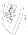
- Figure 1B is an exploded, partial cutaway of the housing from Figure 1A showing one preferred embodiment of distal ribs extending inwardly from the same; .
- Figure 2 is a perspective view of one preferred embodiment of a drum braking mechanism of the present invention as would be attached to a stationary housing frame (not fully shown);
- Figures 3A through 3C are three views for schematically showing the braking mechanism with pawl lockout element of the present invention: (i) in its normal operating state ( Figure 3A ); (ii) in its locked state, engaged with the sperrad teeth after a fall arrest ( Figure 3B ), and (iii) in its lockout mode with the lockout element compressed against a distal rib on the housing interior ( Figure 3C );
- Figure 3D illustrates the increased angle of reverse rotation that can be sustained with the present invention while still remaining in a locked state
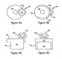
- Figures 4A through 4D are the top, bottom, side and front view of a preferred embodiment of a pawl lockout element of the present invention mounted on a cam follower.
- FIG. 1A there is shown a typical, self-retracting lanyard fully assembled.
- the improved braking mechanism with the pawl lockout element of the present invention is internal to that SRL unit and is not visible in that view. But portions of the same are better illustrated in the exploded, partial cutaway of Figure 1B .
- Such SRL's include a housing 10 about which is wrapped a cover 20, removable for easier servicing. Housing 10 has at its one end (directionally, at the top of Figure 1A ) an anchor connector 30 for the SRL wearer/user to fasten the unit to an anchorage point.
- a load indicator button 40 for quickly showing that this particular unit has not undergone a fall arrest and, as such, is safe to be used that day.
- a line 50 in this case made from nylon webbing, though it is to be understood that the braking mechanism of the present invention can also be used with SRL lines made from metal cables and/or rope, all of which can undergo their own degrees of line rebounding. SRL's with drums of wound webbing are preferred in certain situations because they are usually lighter in weight than their cable counterparts.
- Figure 1A shows the stitching 60 that reinforces the connection of line 50 about snaphook 70. It is to be understood, however, that numerous other means are known for connecting SRL units to a wearer's given safety harness.
- the interior side walls of housing 10 preferably include a distal rib 80.
- rib 80 serves as the fixed or stationary contact point for interacting with a preferred pawl lockout element as described in greater detail below.
- distal rib 80 can be supplemented with, or fully replaced by, an inwardly extending protrusion (or post) from the housing front inner wall and/or an upwardly extending post from the overall SRL frame that runs through housing 10.
- portions of that housing frame are depicted as item F where appropriate.
- a braking mechanism 100 Within housing 10 of the SRL, there is contained a braking mechanism 100. Though not fully shown in Figures 2 and 3A through 3D , that mechanism preferably consists of a plurality of pawls 110 acting beneath a cam plate 120 for a drum/hub unit (not shown) rotatably attached to housing frame F. Line 50 would be repeatedly unwound from, then rewound about that drum/hub unit in the normal operation of this SRL.
- a cam follower 130 fixedly attached to an end of pawl 110.
- Figure 2 there is shown a pair of pawls 110 and cam followers 130 positioned 180 degrees apart beneath a generally hexagonally-shaped, outer cam plate 120.
- cam follower 130 is described in greater detail with respect to Figures 4A through 4D hereinbelow.
- FIG. 3A depicts the typical direction of drum rotation, during web unwinding or pay out from the housing, is indicated by arrow A.
- Figure 3A depicts the normal operating condition of a pawl 110 interacting with teeth 140 that extend outwardly from a sperrad 150 that rotates around a central axis mounting, all beneath the confmes of outer hexagonal cam plate 120.
- Cam follower 130 on pawl 110 moves in conjunction with the perimeter of hexagonal cam plate 120 in this SRL braking mechanism.
- pawl lockout element 220 comprises flexible element 200 mounted on a post 210.
- Flexible element 200 is preferably positioned parallel to the plane of rotation of sperrad 150. For the particular point of rotation depicted in Figure 3A , there is no contact of flexible element 200 on post 210 mounted on cam follower 130 with the distal rib 80 extending inwardly from a sidewall of housing 10.
- the braking mechanism of the present invention In its second mode of operation (as shown in Figure 3B ), the braking mechanism of the present invention has been activated and is in a first locked position. In such a state, tip T of pawl 110 rests in root R of sperrad 150 adjacent a given tooth 140 of that sperrad.
- flexible element 200 on post 210 makes contact with distal rib 80.
- sperrad 150 and cam plate 120 rotate in a reverse direction (indicated by arrow B in Figure 3C ); however, flexible element 200 on post 210 flexibly compresses against distal rib 80 to keep pawl 110 in a locked position relative to sperrad 150.
- Figure 3D better illustrates how the braking mechanism of the present invention is able to increase the maximum permitted rotation of sperrad 150 and thus of the drum to about twenty-eight degrees (angle M), or nearly double the thirteen degree (13°) angle of rotation otherwise achievable by only manipulating relative sperrad tooth and pawl tip geometries to remain in the locked position.
- Figures 4A through 4D show one preferred embodiment of the pawl lockout element of the present invention from a top view perspective ( Figure 4A ), corresponding bottom view ( Figure 4B ), side view ( Figure 4C ) and front view (4D).
- the flexible element 200 preferably an O-ring
- post 210 preferably has a groove G for receiving and holding an O-ring thereon.
- the O-ring is made of a synthetic rubber, more preferably EPDM (an ethylene propylene diene monomer). It is to be understood, however, that other materials can be substituted therefore in order to provide a flexible element for engaging with a stationary component of the SRL unit extending from an interior surface of housing 10 itself and/or from one or more points on the permanent frame F running through the SRL.
- cam follower 130 In the construction of a preferred cam follower 130, there is a cam following surface 132 positioned above a pawl skirt region 134, the latter serving to hold cam follower 130 in place for flexible element 200 to effectively lockout the pawl in contact with skirt region 134. And as better seen in the bottom and front views of Figures 4B and 4D , respectively, cam follower 130 includes a crescent-shaped, lower outer wall 136 that defines a pawl garage 138 that non-rotatably mounts cam follower 130 on one end of pawl 110.
- each pawl 110 in accompanying Figure 2 has its own pawl lockout element, which may or may not be interconnected. If the pawl lockout elements are configured to mechanically lock simultaneously, or near simultaneously, the SRL will have an even more desirable safety redundancy built in.
- pawl lockout elements use a plurality of pawl lockout elements to keep at least one pawl in a locked position, even during rebound when the drum/hub rotation changes direction. While any such pawl lockout element should be flexible and mounted on pawl 110, still similar improvements can be realized in a centrifugally driven brake/clutch, or in the braking elements of other rotational components.
- sperrad having teeth that extend outwardly from a central axis toward the housing interior walls
- a similar system of pawls, plates and lockout elements can be easily implemented in the reverse, i.e., for a braking mechanism in which the sperrad plate extends about the braking mechanism circumference before terminating with inwardly extended or protruding teeth.
- Pawl lockout elements were comparatively tested using both small and large diameter O-rings wrapped about a post mounted on a cam follower.
- the smaller rings exhibited slightly better pawl lockout performance with both ring sizes serving to prevent drum ratcheting while not otherwise interfering with the SRL unit's ability to retract webbing under normal operating conditions.
- the pawl lockout elements in combination with their respective fixed contact points, allow the SRL and braking mechanism of the present invention to meet or exceed all ANSI A10.32 and Z359 standards, and the respective standards of EN and OSHA as well.
Claims (11)
- Longe auto-rétractable à mécanisme de freinage (100) comprenant :(a) un boîtier (10) ;(b) un tambour rotatif dans le boîtier (10) ;(c) une sauvegarde (50) destinée à être enroulée autour du tambour ; et(d) un mécanisme de freinage (100) comprenant : un rochet (150) ; une pluralité de cliquets (110) destinés à s'engager avec une pluralité de dents (140) sur le rochet (150) ; et au moins un élément de verrouillage de cliquet (220) monté sur l'un des cliquets (110) destiné à s'engager de manière souple avec un élément fixe (80) monté dans le boîtier (10) afin de maintenir au moins un cliquet (110) en position verrouillée durant une rotation inverse du tambour, caractérisée en ce que l'élément de verrouillage de cliquet (220) est situé sur un suiveur de came (130) qui est fixé au cliquet (110).
- Longe selon la revendication 1, dans laquelle l'élément de verrouillage de cliquet (220) comprend un matériau déformable en forme de ressort.
- Longe selon la revendication 1 ou la revendication 2, dans laquelle l'élément de verrouillage de cliquet (220) comprend un joint torique.
- Longe selon la revendication 1, dans laquelle l'élément fixe (80) s'étend depuis une paroi intérieure du boîtier (10).
- Longe selon la revendication 1, dans laquelle le mécanisme de freinage (100) comprend deux cliquets (110) espacés de 180 degrés, et le rochet (150) comporte au moins quatre dents (140).
- Longe selon la revendication 5, dans laquelle chaque cliquet (110) comporte un élément de verrouillage de cliquet propre (220).
- Longe selon la revendication 6, dans laquelle chaque élément de verrouillage de cliquet (220) agit indépendamment des autres.
- Longe selon la revendication 1, dans laquelle le rochet (150) a un axe de rotation central comportant des dents (140) qui s'étendent vers l'extérieur vers une circonférence externe.
- Longe selon la revendication 1, dans laquelle la sauvegarde (50) comprend une matière de sangle.
- Longe selon la revendication 3, dans laquelle le joint torique est réalisé en un caoutchouc synthétique.
- Longe selon la revendication 6, dans laquelle les éléments de verrouillage (220) comprennent un matériau de caoutchouc souple.
Priority Applications (1)
| Application Number | Priority Date | Filing Date | Title |
|---|---|---|---|
| PL07716629T PL1993674T3 (pl) | 2006-03-14 | 2007-01-16 | Samoczynnie cofający się ściągacz linowy i mechanizm hamujący z blokadą zapadki |
Applications Claiming Priority (3)
| Application Number | Priority Date | Filing Date | Title |
|---|---|---|---|
| US78205306P | 2006-03-14 | 2006-03-14 | |
| US11/485,710 US7870934B2 (en) | 2006-03-14 | 2006-07-12 | Self-retracting lanyard and braking mechanism with pawl lockout |
| PCT/US2007/001020 WO2007106207A1 (fr) | 2006-03-14 | 2007-01-16 | Sangle auto-retractable et mécanisme de freinage avec blocage à cliquet |
Publications (2)
| Publication Number | Publication Date |
|---|---|
| EP1993674A1 EP1993674A1 (fr) | 2008-11-26 |
| EP1993674B1 true EP1993674B1 (fr) | 2010-04-28 |
Family
ID=37999057
Family Applications (1)
| Application Number | Title | Priority Date | Filing Date |
|---|---|---|---|
| EP07716629A Active EP1993674B1 (fr) | 2006-03-14 | 2007-01-16 | Sangle auto-retractable et mécanisme de freinage avec blocage à cliquet |
Country Status (9)
| Country | Link |
|---|---|
| US (1) | US7870934B2 (fr) |
| EP (1) | EP1993674B1 (fr) |
| CN (1) | CN101405059B (fr) |
| AT (1) | ATE465784T1 (fr) |
| AU (1) | AU2007225417B2 (fr) |
| CA (1) | CA2646360C (fr) |
| DE (1) | DE602007006165D1 (fr) |
| PL (1) | PL1993674T3 (fr) |
| WO (1) | WO2007106207A1 (fr) |
Cited By (1)
| Publication number | Priority date | Publication date | Assignee | Title |
|---|---|---|---|---|
| US11745035B2 (en) | 2019-01-14 | 2023-09-05 | Msa Technology, Llc | Fall protection compliance system and method |
Families Citing this family (26)
| Publication number | Priority date | Publication date | Assignee | Title |
|---|---|---|---|---|
| GB2432140A (en) * | 2005-11-15 | 2007-05-16 | Latchways Plc | Fall arrest safety device |
| GB2440134B (en) * | 2006-07-14 | 2011-04-20 | Latchways Plc | Speed responsive engagement device |
| GB2464277B (en) * | 2008-10-07 | 2013-07-17 | Latchways Plc | Speed responsive engagement device |
| US9080383B2 (en) * | 2009-03-02 | 2015-07-14 | D B Industries, Llc | Climb assist system |
| US8567562B2 (en) * | 2009-11-02 | 2013-10-29 | B D Industries, LLC | Brake assembly for a self-retracting lifeline assembly |
| CA2795336C (fr) * | 2010-04-06 | 2019-06-25 | Sperian Fall Protection Inc. | Systemes de filin de securite retractable destines a etre utilises pour l'arrimage facon embrasse |
| US9199103B2 (en) | 2010-05-12 | 2015-12-01 | Msa Technology, Llc | Fall protection arrangement |
| US8469149B2 (en) | 2010-06-07 | 2013-06-25 | D B Industries, Llc | Self-retracting lifeline with disconnectable lifeline |
| US8430207B2 (en) * | 2010-06-23 | 2013-04-30 | 3M Innovative Properties Company | Preassembled and pretorqued friction brake and method of making a safety device containing such a friction brake |
| US8974334B2 (en) | 2011-10-14 | 2015-03-10 | D B Industries, Llc | Cable drive and tension assembly |
| US9121462B2 (en) * | 2011-10-28 | 2015-09-01 | D B Industries, Llc | Self-retracting lifeline |
| CN102389624B (zh) * | 2011-11-22 | 2013-07-10 | 何少敦 | 一种空中降落器的制动装置 |
| US10004927B2 (en) | 2012-12-02 | 2018-06-26 | Reliance Industries, Llc | Retractable lanyard lock mechanism |
| US9707421B2 (en) | 2013-02-08 | 2017-07-18 | D B Industries, Llc | Energy absorber cover |
| GB2512064B (en) * | 2013-03-18 | 2018-05-23 | Latchways Plc | Tether System for a Safety Line |
| DE102015109444B4 (de) * | 2015-06-12 | 2018-08-02 | Bornack Gmbh & Co. Kg | Seilsicherungsvorrichtung |
| US10143867B2 (en) * | 2016-11-29 | 2018-12-04 | Aerohook Technology Co., Ltd. | Dual-suspensible anti-falling device |
| CN110075433B (zh) * | 2018-01-25 | 2021-10-29 | 东莞市红火安全科技有限公司 | 一种控速防坠器 |
| US11633634B2 (en) * | 2018-04-06 | 2023-04-25 | Msa Technology, Llc | Cut-resistant leading edge fall arrest system and method |
| US11872419B1 (en) | 2018-06-01 | 2024-01-16 | OTEX Specialty Narrow Fabrics, Inc. | Webbing for fall protection device |
| CN114761089B (zh) * | 2019-09-20 | 2024-03-15 | 特鲁布鲁有限公司 | 锁止下降控制系统和装置 |
| CN111228676B (zh) * | 2020-01-15 | 2021-07-06 | 泉州市宏盼机械科技有限公司 | 一种基站信号塔用安全绳防冲击装置 |
| US11390969B1 (en) | 2020-01-27 | 2022-07-19 | OTEX Specialty Narrow Fabrics, Inc. | Webbing for fall protection device |
| US11534634B2 (en) | 2020-04-03 | 2022-12-27 | Honeywell International Inc. | Brake assembly for fall arrest system |
| CN111939496B (zh) * | 2020-08-24 | 2021-04-23 | 杭州合泰安防科技有限公司 | 一种手柄式防坠器 |
| US20220176173A1 (en) * | 2020-12-07 | 2022-06-09 | Werner Co. | Self-retracting lifeline housing |
Family Cites Families (18)
| Publication number | Priority date | Publication date | Assignee | Title |
|---|---|---|---|---|
| US681099A (en) | 1900-05-08 | 1901-08-20 | Anders Bull | Method by which several telegraphic messages can be transmitted at the same time through one conductor or by wireless telegraphy. |
| FR1270109A (fr) | 1960-07-15 | 1961-08-25 | Appareil de sécurité antichute | |
| US3150744A (en) * | 1961-07-21 | 1964-09-29 | Fertier Raymond | Individual safety elevator |
| GB999552A (en) | 1962-03-30 | 1965-07-28 | Joseph Trouin | Safety apparatus |
| US3760910A (en) | 1972-04-14 | 1973-09-25 | A Koshihara | Safety device |
| US4511123A (en) * | 1983-06-02 | 1985-04-16 | Meyer Ostrobrod | Safety device |
| US4877110A (en) | 1988-10-14 | 1989-10-31 | D B Industries, Inc. | Safety device with retractable lifeline |
| US5186289A (en) | 1990-10-26 | 1993-02-16 | D B Industries, Inc. | Retractable lifeline safety device |
| JPH0572612U (ja) * | 1992-03-09 | 1993-10-05 | 株式会社東海理化電機製作所 | ウエビング巻取装置 |
| EP0739225B1 (fr) * | 1994-01-13 | 1997-12-29 | Barrow Hepburn Sala Limited | Dispositif de couplage reagissant a la vitesse, con u en particulier pour des dispositifs antichute |
| GB2345271B (en) * | 1999-01-04 | 2002-06-05 | Breed Automotive Tech | Retractor |
| JP4323081B2 (ja) * | 2000-10-26 | 2009-09-02 | 株式会社東海理化電機製作所 | ウエビング巻取装置 |
| US7857099B2 (en) * | 2001-04-24 | 2010-12-28 | Reliance Industries, Llc | Twin retractable for fall arrest |
| EP1545713B1 (fr) | 2002-10-04 | 2008-04-09 | Mine Safety Appliances Company | Baudrier complet permettant d'arreter une chute |
| DE10310020A1 (de) * | 2003-02-28 | 2004-09-09 | Takata-Petri (Ulm) Gmbh | Gurtaufroller für einen Sicherheitsgurt |
| US7281620B2 (en) | 2003-09-05 | 2007-10-16 | D B Industries, Inc. | Self-retracting lifeline |
| CA2607843C (fr) | 2004-05-07 | 2011-02-15 | Leigh Dowie | Appareil de securite |
| US7406773B2 (en) * | 2004-12-23 | 2008-08-05 | Irwin Industrial Tool Company | Magnet assembly |
-
2006
- 2006-07-12 US US11/485,710 patent/US7870934B2/en active Active
-
2007
- 2007-01-16 AU AU2007225417A patent/AU2007225417B2/en active Active
- 2007-01-16 AT AT07716629T patent/ATE465784T1/de not_active IP Right Cessation
- 2007-01-16 EP EP07716629A patent/EP1993674B1/fr active Active
- 2007-01-16 WO PCT/US2007/001020 patent/WO2007106207A1/fr active Application Filing
- 2007-01-16 DE DE602007006165T patent/DE602007006165D1/de active Active
- 2007-01-16 CN CN2007800092497A patent/CN101405059B/zh not_active Expired - Fee Related
- 2007-01-16 CA CA2646360A patent/CA2646360C/fr active Active
- 2007-01-16 PL PL07716629T patent/PL1993674T3/pl unknown
Cited By (1)
| Publication number | Priority date | Publication date | Assignee | Title |
|---|---|---|---|---|
| US11745035B2 (en) | 2019-01-14 | 2023-09-05 | Msa Technology, Llc | Fall protection compliance system and method |
Also Published As
| Publication number | Publication date |
|---|---|
| PL1993674T3 (pl) | 2010-09-30 |
| CN101405059A (zh) | 2009-04-08 |
| EP1993674A1 (fr) | 2008-11-26 |
| US20070215410A1 (en) | 2007-09-20 |
| US7870934B2 (en) | 2011-01-18 |
| AU2007225417A1 (en) | 2007-09-20 |
| CN101405059B (zh) | 2011-12-07 |
| AU2007225417B2 (en) | 2011-11-10 |
| ATE465784T1 (de) | 2010-05-15 |
| WO2007106207A1 (fr) | 2007-09-20 |
| CA2646360A1 (fr) | 2007-09-20 |
| CA2646360C (fr) | 2015-05-26 |
| DE602007006165D1 (de) | 2010-06-10 |
Similar Documents
| Publication | Publication Date | Title |
|---|---|---|
| EP1993674B1 (fr) | Sangle auto-retractable et mécanisme de freinage avec blocage à cliquet | |
| EP2777771B1 (fr) | Dispositif de sécurité antichute avec mécanisme de freinage | |
| US4877110A (en) | Safety device with retractable lifeline | |
| JP5497074B2 (ja) | 落下阻止及び降下モード備えた安全装置 | |
| EP2432564B1 (fr) | Cordage de sécurité auto-rétractable avec partie de réserve | |
| EP2845626B1 (fr) | Agencement de protection contre les chutes | |
| US4489919A (en) | Safety winch with disengageable drive | |
| GB2451835A (en) | Fall arrest block | |
| WO1997047359A1 (fr) | Dispositifs de securite anti-chute | |
| JP2007537790A (ja) | 個人的高所救出装置 | |
| CN110290839B (zh) | 坠落保护装置及其调节机构 | |
| AU2010205907B2 (en) | Self-retracting lifeline | |
| US20220105374A1 (en) | Self-Retracting Device and Axle Therefor | |
| EP0687482A2 (fr) | Dispositif et procédé d'arrêt de chute | |
| US20230310910A1 (en) | Systems and Methods for Providing a Consolidated PFL or SRL Drum | |
| KR20240020838A (ko) | 드래그 다운먼트 | |
| GB2399564A (en) | Safety system for retaining tools |
Legal Events
| Date | Code | Title | Description |
|---|---|---|---|
| PUAI | Public reference made under article 153(3) epc to a published international application that has entered the european phase |
Free format text: ORIGINAL CODE: 0009012 |
|
| 17P | Request for examination filed |
Effective date: 20080926 |
|
| AK | Designated contracting states |
Kind code of ref document: A1 Designated state(s): AT BE BG CH CY CZ DE DK EE ES FI FR GB GR HU IE IS IT LI LT LU LV MC NL PL PT RO SE SI SK TR |
|
| GRAP | Despatch of communication of intention to grant a patent |
Free format text: ORIGINAL CODE: EPIDOSNIGR1 |
|
| GRAS | Grant fee paid |
Free format text: ORIGINAL CODE: EPIDOSNIGR3 |
|
| GRAA | (expected) grant |
Free format text: ORIGINAL CODE: 0009210 |
|
| AK | Designated contracting states |
Kind code of ref document: B1 Designated state(s): AT BE BG CH CY CZ DE DK EE ES FI FR GB GR HU IE IS IT LI LT LU LV MC NL PL PT RO SE SI SK TR |
|
| REG | Reference to a national code |
Ref country code: GB Ref legal event code: FG4D |
|
| REG | Reference to a national code |
Ref country code: CH Ref legal event code: EP |
|
| REG | Reference to a national code |
Ref country code: IE Ref legal event code: FG4D |
|
| REF | Corresponds to: |
Ref document number: 602007006165 Country of ref document: DE Date of ref document: 20100610 Kind code of ref document: P |
|
| REG | Reference to a national code |
Ref country code: NL Ref legal event code: VDEP Effective date: 20100428 |
|
| LTIE | Lt: invalidation of european patent or patent extension |
Effective date: 20100428 |
|
| REG | Reference to a national code |
Ref country code: PL Ref legal event code: T3 |
|
| PG25 | Lapsed in a contracting state [announced via postgrant information from national office to epo] |
Ref country code: LT Free format text: LAPSE BECAUSE OF FAILURE TO SUBMIT A TRANSLATION OF THE DESCRIPTION OR TO PAY THE FEE WITHIN THE PRESCRIBED TIME-LIMIT Effective date: 20100428 Ref country code: NL Free format text: LAPSE BECAUSE OF FAILURE TO SUBMIT A TRANSLATION OF THE DESCRIPTION OR TO PAY THE FEE WITHIN THE PRESCRIBED TIME-LIMIT Effective date: 20100428 Ref country code: SE Free format text: LAPSE BECAUSE OF FAILURE TO SUBMIT A TRANSLATION OF THE DESCRIPTION OR TO PAY THE FEE WITHIN THE PRESCRIBED TIME-LIMIT Effective date: 20100428 Ref country code: ES Free format text: LAPSE BECAUSE OF FAILURE TO SUBMIT A TRANSLATION OF THE DESCRIPTION OR TO PAY THE FEE WITHIN THE PRESCRIBED TIME-LIMIT Effective date: 20100808 |
|
| PG25 | Lapsed in a contracting state [announced via postgrant information from national office to epo] |
Ref country code: SI Free format text: LAPSE BECAUSE OF FAILURE TO SUBMIT A TRANSLATION OF THE DESCRIPTION OR TO PAY THE FEE WITHIN THE PRESCRIBED TIME-LIMIT Effective date: 20100428 Ref country code: IS Free format text: LAPSE BECAUSE OF FAILURE TO SUBMIT A TRANSLATION OF THE DESCRIPTION OR TO PAY THE FEE WITHIN THE PRESCRIBED TIME-LIMIT Effective date: 20100828 Ref country code: FI Free format text: LAPSE BECAUSE OF FAILURE TO SUBMIT A TRANSLATION OF THE DESCRIPTION OR TO PAY THE FEE WITHIN THE PRESCRIBED TIME-LIMIT Effective date: 20100428 Ref country code: AT Free format text: LAPSE BECAUSE OF FAILURE TO SUBMIT A TRANSLATION OF THE DESCRIPTION OR TO PAY THE FEE WITHIN THE PRESCRIBED TIME-LIMIT Effective date: 20100428 Ref country code: LV Free format text: LAPSE BECAUSE OF FAILURE TO SUBMIT A TRANSLATION OF THE DESCRIPTION OR TO PAY THE FEE WITHIN THE PRESCRIBED TIME-LIMIT Effective date: 20100428 |
|
| PG25 | Lapsed in a contracting state [announced via postgrant information from national office to epo] |
Ref country code: CY Free format text: LAPSE BECAUSE OF FAILURE TO SUBMIT A TRANSLATION OF THE DESCRIPTION OR TO PAY THE FEE WITHIN THE PRESCRIBED TIME-LIMIT Effective date: 20100602 |
|
| PG25 | Lapsed in a contracting state [announced via postgrant information from national office to epo] |
Ref country code: EE Free format text: LAPSE BECAUSE OF FAILURE TO SUBMIT A TRANSLATION OF THE DESCRIPTION OR TO PAY THE FEE WITHIN THE PRESCRIBED TIME-LIMIT Effective date: 20100428 Ref country code: DK Free format text: LAPSE BECAUSE OF FAILURE TO SUBMIT A TRANSLATION OF THE DESCRIPTION OR TO PAY THE FEE WITHIN THE PRESCRIBED TIME-LIMIT Effective date: 20100428 Ref country code: PT Free format text: LAPSE BECAUSE OF FAILURE TO SUBMIT A TRANSLATION OF THE DESCRIPTION OR TO PAY THE FEE WITHIN THE PRESCRIBED TIME-LIMIT Effective date: 20100830 |
|
| RAP2 | Party data changed (patent owner data changed or rights of a patent transferred) |
Owner name: MINE SAFETY APPLIANCES COMPANY |
|
| PG25 | Lapsed in a contracting state [announced via postgrant information from national office to epo] |
Ref country code: SK Free format text: LAPSE BECAUSE OF FAILURE TO SUBMIT A TRANSLATION OF THE DESCRIPTION OR TO PAY THE FEE WITHIN THE PRESCRIBED TIME-LIMIT Effective date: 20100428 Ref country code: BE Free format text: LAPSE BECAUSE OF FAILURE TO SUBMIT A TRANSLATION OF THE DESCRIPTION OR TO PAY THE FEE WITHIN THE PRESCRIBED TIME-LIMIT Effective date: 20100428 Ref country code: CZ Free format text: LAPSE BECAUSE OF FAILURE TO SUBMIT A TRANSLATION OF THE DESCRIPTION OR TO PAY THE FEE WITHIN THE PRESCRIBED TIME-LIMIT Effective date: 20100428 Ref country code: RO Free format text: LAPSE BECAUSE OF FAILURE TO SUBMIT A TRANSLATION OF THE DESCRIPTION OR TO PAY THE FEE WITHIN THE PRESCRIBED TIME-LIMIT Effective date: 20100428 |
|
| PLBE | No opposition filed within time limit |
Free format text: ORIGINAL CODE: 0009261 |
|
| STAA | Information on the status of an ep patent application or granted ep patent |
Free format text: STATUS: NO OPPOSITION FILED WITHIN TIME LIMIT |
|
| PG25 | Lapsed in a contracting state [announced via postgrant information from national office to epo] |
Ref country code: IT Free format text: LAPSE BECAUSE OF FAILURE TO SUBMIT A TRANSLATION OF THE DESCRIPTION OR TO PAY THE FEE WITHIN THE PRESCRIBED TIME-LIMIT Effective date: 20100428 |
|
| 26N | No opposition filed |
Effective date: 20110131 |
|
| PG25 | Lapsed in a contracting state [announced via postgrant information from national office to epo] |
Ref country code: GR Free format text: LAPSE BECAUSE OF FAILURE TO SUBMIT A TRANSLATION OF THE DESCRIPTION OR TO PAY THE FEE WITHIN THE PRESCRIBED TIME-LIMIT Effective date: 20100729 |
|
| PG25 | Lapsed in a contracting state [announced via postgrant information from national office to epo] |
Ref country code: MC Free format text: LAPSE BECAUSE OF NON-PAYMENT OF DUE FEES Effective date: 20110131 |
|
| REG | Reference to a national code |
Ref country code: CH Ref legal event code: PL |
|
| REG | Reference to a national code |
Ref country code: IE Ref legal event code: MM4A |
|
| PG25 | Lapsed in a contracting state [announced via postgrant information from national office to epo] |
Ref country code: CH Free format text: LAPSE BECAUSE OF NON-PAYMENT OF DUE FEES Effective date: 20110131 Ref country code: LI Free format text: LAPSE BECAUSE OF NON-PAYMENT OF DUE FEES Effective date: 20110131 |
|
| PG25 | Lapsed in a contracting state [announced via postgrant information from national office to epo] |
Ref country code: IE Free format text: LAPSE BECAUSE OF NON-PAYMENT OF DUE FEES Effective date: 20110116 |
|
| PG25 | Lapsed in a contracting state [announced via postgrant information from national office to epo] |
Ref country code: LU Free format text: LAPSE BECAUSE OF NON-PAYMENT OF DUE FEES Effective date: 20110116 |
|
| PG25 | Lapsed in a contracting state [announced via postgrant information from national office to epo] |
Ref country code: TR Free format text: LAPSE BECAUSE OF FAILURE TO SUBMIT A TRANSLATION OF THE DESCRIPTION OR TO PAY THE FEE WITHIN THE PRESCRIBED TIME-LIMIT Effective date: 20100428 Ref country code: BG Free format text: LAPSE BECAUSE OF FAILURE TO SUBMIT A TRANSLATION OF THE DESCRIPTION OR TO PAY THE FEE WITHIN THE PRESCRIBED TIME-LIMIT Effective date: 20100728 |
|
| PG25 | Lapsed in a contracting state [announced via postgrant information from national office to epo] |
Ref country code: HU Free format text: LAPSE BECAUSE OF FAILURE TO SUBMIT A TRANSLATION OF THE DESCRIPTION OR TO PAY THE FEE WITHIN THE PRESCRIBED TIME-LIMIT Effective date: 20100428 |
|
| REG | Reference to a national code |
Ref country code: GB Ref legal event code: 732E Free format text: REGISTERED BETWEEN 20140619 AND 20140625 |
|
| REG | Reference to a national code |
Ref country code: FR Ref legal event code: TP Owner name: MSA TECHNOLOGY, LLC, US Effective date: 20140912 |
|
| REG | Reference to a national code |
Ref country code: DE Ref legal event code: R082 Ref document number: 602007006165 Country of ref document: DE Representative=s name: MAIKOWSKI & NINNEMANN PATENTANWAELTE, DE |
|
| REG | Reference to a national code |
Ref country code: DE Ref legal event code: R082 Ref document number: 602007006165 Country of ref document: DE Representative=s name: MAIKOWSKI & NINNEMANN PATENTANWAELTE PARTNERSC, DE Effective date: 20150223 Ref country code: DE Ref legal event code: R082 Ref document number: 602007006165 Country of ref document: DE Representative=s name: MAIKOWSKI & NINNEMANN PATENTANWAELTE PARTNERSC, DE Effective date: 20150126 Ref country code: DE Ref legal event code: R081 Ref document number: 602007006165 Country of ref document: DE Owner name: MSA TECHNOLOGY, LLC, CRANBERRY TOWNSHIP, US Free format text: FORMER OWNER: MINE SAFETY APPLIANCES CO., PITTSBURGH, PA., US Effective date: 20150126 Ref country code: DE Ref legal event code: R082 Ref document number: 602007006165 Country of ref document: DE Representative=s name: MAIKOWSKI & NINNEMANN PATENTANWAELTE, DE Effective date: 20150223 Ref country code: DE Ref legal event code: R082 Ref document number: 602007006165 Country of ref document: DE Representative=s name: MAIKOWSKI & NINNEMANN PATENTANWAELTE, DE Effective date: 20150126 Ref country code: DE Ref legal event code: R081 Ref document number: 602007006165 Country of ref document: DE Owner name: MSA TECHNOLOGY, LLC, CRANBERRY TOWNSHIP, US Free format text: FORMER OWNER: MINE SAFETY APPLIANCES COMP., LLC, CRANBERRY TOWNSHIP, PA., US Effective date: 20150223 Ref country code: DE Ref legal event code: R081 Ref document number: 602007006165 Country of ref document: DE Owner name: MINE SAFETY APPLIANCES COMP., LLC, CRANBERRY T, US Free format text: FORMER OWNER: MINE SAFETY APPLIANCES CO., PITTSBURGH, PA., US Effective date: 20150126 |
|
| REG | Reference to a national code |
Ref country code: FR Ref legal event code: PLFP Year of fee payment: 10 |
|
| REG | Reference to a national code |
Ref country code: FR Ref legal event code: PLFP Year of fee payment: 11 |
|
| REG | Reference to a national code |
Ref country code: FR Ref legal event code: PLFP Year of fee payment: 12 |
|
| REG | Reference to a national code |
Ref country code: DE Ref legal event code: R082 Ref document number: 602007006165 Country of ref document: DE Representative=s name: JONES DAY RECHTSANWAELTE PATENTANWAELTE, DE |
|
| P01 | Opt-out of the competence of the unified patent court (upc) registered |
Effective date: 20230626 |
|
| PGFP | Annual fee paid to national office [announced via postgrant information from national office to epo] |
Ref country code: GB Payment date: 20231130 Year of fee payment: 18 |
|
| PGFP | Annual fee paid to national office [announced via postgrant information from national office to epo] |
Ref country code: FR Payment date: 20231212 Year of fee payment: 18 |
|
| PGFP | Annual fee paid to national office [announced via postgrant information from national office to epo] |
Ref country code: PL Payment date: 20231211 Year of fee payment: 18 |
|
| PGFP | Annual fee paid to national office [announced via postgrant information from national office to epo] |
Ref country code: DE Payment date: 20231205 Year of fee payment: 18 |