EP1992927A1 - Electronically commuted asynchronous motor - Google Patents
Electronically commuted asynchronous motor Download PDFInfo
- Publication number
- EP1992927A1 EP1992927A1 EP08001598A EP08001598A EP1992927A1 EP 1992927 A1 EP1992927 A1 EP 1992927A1 EP 08001598 A EP08001598 A EP 08001598A EP 08001598 A EP08001598 A EP 08001598A EP 1992927 A1 EP1992927 A1 EP 1992927A1
- Authority
- EP
- European Patent Office
- Prior art keywords
- sensor
- temperature
- motor
- rotor
- motor according
- Prior art date
- Legal status (The legal status is an assumption and is not a legal conclusion. Google has not performed a legal analysis and makes no representation as to the accuracy of the status listed.)
- Granted
Links
Images

Classifications
-
- G—PHYSICS
- G01—MEASURING; TESTING
- G01K—MEASURING TEMPERATURE; MEASURING QUANTITY OF HEAT; THERMALLY-SENSITIVE ELEMENTS NOT OTHERWISE PROVIDED FOR
- G01K7/00—Measuring temperature based on the use of electric or magnetic elements directly sensitive to heat ; Power supply therefor, e.g. using thermoelectric elements
- G01K7/36—Measuring temperature based on the use of electric or magnetic elements directly sensitive to heat ; Power supply therefor, e.g. using thermoelectric elements using magnetic elements, e.g. magnets, coils
Definitions
- ASM asynchronous motors
- stator resistance and the rotor resistance can change by up to 50% depending on the temperature. Changes in the main inductance must be taken into account when the ASM is also operated in the field weakening range.
- this object is achieved by the subject matter of claim 1. It succeeds in a very simple manner to measure the temperature of the rotor without contact.
- a further preferred embodiment is the subject of claim 15.
- the use of a magnetoresistive sensor makes it possible, for example, to use a magnetoresistive sensor. a simultaneous measurement of the temperature and the rotational position and therefore saves costs.
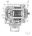
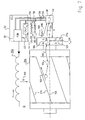
- the rings 206, 208 are connected in the usual way by shorting bars 210 into a cage in which a rotor current i R flows in operation, the size of which depends from the temperature of the rotor 204, because the resistance of the bars 210 increases with increasing temperature. For this reason, the height of the current must be adjusted depending on the rotor temperature, and for this reason, a temperature sensor whose position is indicated by the reference numeral 214 and which indirectly detects the temperature of the rotor 204 is integrated into the stator winding. The signal from this sensor 214 is fed to a field-oriented control (FOR) controller 20, which in Fig. 2 is shown.
- FOR field-oriented control
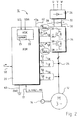
- FIG. 1 shows a control arrangement 10 for the ASM 12. It has an encoder arrangement 14 for generating a speed signal n, and also an encoder arrangement 14A (FIG. Fig. 1 ) for generating a Hall signal HALL and a signal MR from a magnetoresistive resistor 18 (FIG. Fig. 2 ).
- the encoder arrangement 14 includes a sensor magnet 274.
- the sensor magnet 274 also controls the magnetoresistor 18, which serves for the exact detection of the rotor position.
- the rotor position can also be calculated directly from the Hall signal HALL.
- the FOR 20 is also supplied at an input 50 with a value n * for the desired speed of the motor 10. Furthermore, values i1, i2, i3 for the phase currents are applied to inputs 52, 54, and values u1, u2, u3 for the phase voltages of the respective phases of the motor 12 are applied to inputs 56, 58.
- the currents i1 etc. are z. Example by means of current transformers 24 of known type, of which only one is shown because Fig. 1 a common symbolic representation for such a motor.
- a three-phase inverter 34 is connected, of which only one of the three branches is shown.
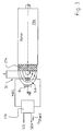
- Fig. 4 12 shows a schematic representation of the stator 202, the rotor 204 with the short-circuit bars 210 and with the sensor magnet 274, the galvanomagnetic sensor 14A, the MR sensor 18 for detecting the rotor position angle phi, and the ECU 33, which comprises a FOR 20 and a temperature evaluation device 44 Has.
- the temperature T_M 104 influenced by heat transfer 105, in particular by heat conduction, the temperature T_SM 106 of the sensor magnet 274, so that T_SM ⁇ T_M is.
- the sensor magnet 274 z. B. rotatably connected via a thermally conductive material with the rotor 204.
- the sensor magnet 274 rotates with the rotor 204 and generates a magnetic Flux density B (phi, T_SM) 108, which is dependent on the rotor position angle phi and the temperature T_SM 106 of the sensor magnet 274, wherein the amplitude of the magnetic flux density B 108 decreases with increasing temperature T_SM 106 of the sensor magnet 274.
- the determined voltage U112 is supplied to the temperature evaluation device CALC_T 44.
- T_SM amplitude f
- the determined temperature value T 45 is then supplied to the FOR 20, and this can perform an improved field-oriented control with the aid of the value T 45 and the rotor position angle phi determined by the MR sensor 18.
- the measurement of the temperature-dependent magnetic flux density 108 by means of a galvanomagnetic sensor 14A responds more quickly to temperature changes in the motor 12 than the measurement of the temperature at the location of the sensor 14A (for example, by an NTC resistor), since the heat transfer is not instantaneous, and therefore a temperature measurement at the location of the sensor 14A with respect to the temperature of the engine is delayed.
- the distance d ( Fig. 3 ) between the sensor magnet 274 and the galvanomagnetic sensor 14A is preferably selected such that it lies at approximately 2/3 of the radius r_SM 120 of the sensor magnet 274.
- r_SM is about 7 mm, and thus about 5 mm.
- a stator-side partition or cap 122 (FIG. Fig. 1 ) is provided between the sensor 14A and the sensor magnet 274, for. B. to protect the sensor 14A before engine-internal media such.
- the cap 122 is preferably made of a poor thermal conductivity material such. B. plastic designed to reduce heating of the sensor 14A.
- the sensor 14A can conduct heat well with the sensor housing 124 (FIG. Fig. 1 ) are thermally connected to maintain the temperature of the sensor 14A at about ambient temperature. This is when galvanomagnetic Sensors 14A with dependent on the temperature of the sensor 14A output signal 110 reduces an influence on the output signal 110 by heating the sensor 14A, which facilitates the evaluation.
- galvanomagnetic sensors 14A are used with compensation for the dependence on the sensor temperature.
- Such compensation is z. B. in the silicon of the sensor 14A possible.
- a suitable galvanomagnetic sensor 14A is e.g. Hall sensor HW-1 01 A from ASAHI KASEI EMD CORPORATION (AKE).
- a solution without an MR sensor 18 or 18 ' is also possible.
- two analog galvanomagnetic sensors 14A are used to generate two non-identical sine signals, preferably a sine signal and a cosine signal. The temperature can then be determined either from one or both signals.
- Fig. 5 shows from the data sheet of the Hall sensor HW-101A a characteristic V H -B with the output voltage V H and the magnetic flux density B, and Fig. 6 a characteristic V H -T with the output voltage V H and the temperature T.
- the output voltage V H increases linearly with the amount of the magnetic flux density B, provided that the input voltage Vc is kept constant.
- the level of the output voltage V H in the operating range -40 ° C to + 110 ° C of the temperature at a constant input voltage V C remains substantially constant.
- the voltage generated by the Hall sensor 14A voltage U 112 thus essentially depends on the - direction-independent - magnetic flux density B.
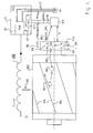
- Fig. 7 shows a schematic diagram of a measurement of the engine temperature T_M 104 by means of a relative to the rotor axis 150 centrally disposed MR sensor 18 '.
- the starting point is that the temperature T_SM of the sensor magnet 274 represents a sufficient image of the temperature T_M 104 of the short-circuit rotor 204.
- the MR sensor 18 ' (eg, an AMR, GMR, or CMR sensor) is positioned relative to the sensor magnet 274 such that heat transfer 134 from the sensor magnet 274 to the sensor 18' occurs, particularly by heat radiation and convection ,
- MR sensors 18 ' are used whose output signals 130, 132 in the specified range depend only slightly on the strength of the magnetic flux density B 108, but mainly on their direction (also called magnetic field direction), or in which the dependence on the magnetic flux density B is at least less than that of the temperature of the MR sensor 18 '.
- the output voltage decreases by about 0.29% / K, and it is substantially independent of the amount of magnetic field in the working region (usually in the saturation region with respect to the magnetic flux density B) Flux density B.
- the method is not as accurate as z.
- the solution is therefore very favorable because both the rotor position angle phi and the approximate temperature (T_M) 104 of the short-circuit rotor 204 can be determined with the MR sensor 140.
- the distance d between the sensor magnet 274 and the MR sensor 18 ' is preferably chosen small, z. B. 1 mm to 4 mm, more preferably 1.5 mm to 3 mm to allow a good heat transfer 134.
- stator-side partition or cap 122 (FIG. Fig. 1 ) between the sensor 18 'and the sensor magnet 274 to protect the sensor 18'.
- the partition 122 is made of a good heat conducting material such.
- a good heat conducting material such as a metal, in particular aluminum.
- the senor 18 or 18 'with respect to the usually good thermal conductivity sensor housing 124 are thermally insulated to reduce cooling therethrough.
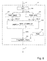
- Fig. 8 1 shows an exemplary embodiment of a temperature evaluation device (temperature determination device, temperature detection device) 44 for evaluating a temperature-dependent sensor signal U1 from a galvanomagnetic sensor 14A (FIG. Fig. 4 ) or an MR sensor 18 '( Fig. 7 ).
- a temperature evaluation device temperature determination device, temperature detection device 44 for evaluating a temperature-dependent sensor signal U1 from a galvanomagnetic sensor 14A (FIG. Fig. 4 ) or an MR sensor 18 '( Fig. 7 ).
- the device 44 is designed here as an ASIC, but can, for. B. also be formed in a microprocessor or microcontroller.
- the temperature-dependent signal U1 is fed to an A / D converter 304 and digitized there.
- the output signal U1_dig is fed to a function FIND_MAX 308 and a function FIND_MIN 310, which determine, for example, the maximum value MAX_U1 312 and the minimum value MIN_U1 314 over a predetermined period of time. For this purpose, z. B. during a period of the sinusoidal signal U1, the largest value and the smallest value are determined. Subsequently, at 316, the amplitude AMPL is calculated by calculating half of the difference between the maximum value MAX_U1 and the minimum value MIN_U1.
- the temperature T is subsequently determined from the amplitude AMPL and possibly further parameters PAR dependent on the motor or sensor by a function g (AMPL, PAR).
- the motor-dependent parameters PAR are z.
- EEPROM 320 Fig. 8
- the determination of the temperature can z.
- the parameter PAR 320 can be fixed for the engine type, with a higher requirement
- the accuracy or large tolerances may also be necessary, at least partially, for each individual rotor 204 determined specification of the parameters, wherein z. B. measurements are carried out at predetermined temperatures.
- the temperature can be determined either only from one of the two signals, or both. Upon detection of a sine and a cosine signal, these can be applied in a known manner as a circle, and the temperature results from its radius.
- the present type of temperature measurement can also be used with BLDC motors (brushless DC motors or electronically commutated DC motors) to allow regulation with a more accurate motor model.
- BLDC motors brushless DC motors or electronically commutated DC motors
- sensors 14A and 18, 18 ' which i.a. are dependent both on the magnitude of the magnetic flux density B and on the temperature T_S of the sensor 18, 18 '.
- this can complicate the evaluation, and the effects can cancel each other or negatively influence. Possibly.
- the characteristic of the determined voltage above the motor temperature must be measured in advance in the engine 12.
- both are preferably arranged on the same side of the printed circuit board; in the case of a galvanomagnetic and an MR sensor, either both sensors are preferably arranged on the same side of the printed circuit board, or one of the sensors is on the front side of the printed circuit board and the other on its rear side arranged.
- MR sensors are preferably used in the region of the axis of rotation 150 (FIG. Fig. 4 . Fig. 7 ) of the rotor or the sensor magnet 106 and thus arranged centrally, while galvanomagnetic sensors can be positioned relatively freely, especially in the exclusive use for temperature determination, as long as the magnetic flux density at the selected position is still large enough.
Abstract
Description
Die Erfindung betrifft einen elektronisch kommutierten Asynchronmotor mit einem Stator, einem Kurzschlussrotor, und einem Regler für die feldorientierte Regelung dieses Motors.The invention relates to an electronically commutated induction motor with a stator, a short-circuit rotor, and a controller for the field-oriented control of this engine.
Die Erfassung der elektrischen Parameter von Asynchronmotoren (ASM) ist für die feldorientierte Regelung der produzierten Motoren bedeutsam.The detection of the electrical parameters of asynchronous motors (ASM) is important for the field-oriented control of the motors produced.
Obwohl die feldorientierte Regelung (FOR) von Asynchronmotoren bekannt ist, stellt ihre Empfindlichkeit gegenüber Parameteränderungen ein Problem dar, das nur unbefriedigend gelöst ist. Bei der FOR erfolgt die Regelung in einem am Läuferfluss-Raumzeiger orientierten Koordinatensystem, wodurch eine getrennte Beeinflussung der flussbildenden und der drehmomentbildenden Stromkomponenten möglich ist. Die Bestimmung der momentanen Lage und des momentanen Betrags des Läuferfluss-Raumzeigers erfolgt meistens mit Hilfe eines Motormodells. Alle Schätzverfahren für den Läuferfluss, denen ein Modell zugrunde liegt, haben aber den Nachteil, dass das Parallelmodell nur dann den Motorzustand richtig wiedergeben kann, wenn die Modellparameter mit den aktuellen Motorparametern übereinstimmen.Although the field-oriented control (FOR) of asynchronous motors is known, its sensitivity to parameter changes presents a problem that has been unsatisfactorily solved. In the case of the FOR, the control takes place in a coordinate system oriented on the rotor flux space vector, whereby a separate influencing of the flow-forming and the torque-forming current components is possible. The determination of the current position and the instantaneous amount of the rotor flux space vector is usually carried out with the aid of a motor model. However, all estimator methods for the rotor flow that underlie a model have the disadvantage that the parallel model can only correctly reflect the engine condition if the model parameters match the current engine parameters.
Im Betrieb können sich der Statorwiderstand und der Rotorwiderstand abhängig von der Temperatur um bis zu 50 % ändern. Änderungen der Hauptinduktivität sind dann zu berücksichtigen, wenn der ASM auch im Feldschwächbereich betrieben wird.During operation, the stator resistance and the rotor resistance can change by up to 50% depending on the temperature. Changes in the main inductance must be taken into account when the ASM is also operated in the field weakening range.
Es ist deshalb eine Aufgabe der Erfindung, einen neuen elektronisch kommutierten Asynchronmotor bereit zu stellen, welcher sich besonders für die feldorientierte Regelung eignet.It is therefore an object of the invention to provide a new electronically commutated induction motor, which is particularly suitable for field-oriented control.
Nach der Erfindung wird diese Aufgabe gelöst durch den Gegenstand des Anspruchs 1. Es gelingt so in sehr einfacher Weise, die Temperatur des Rotors berührungslos zu messen.According to the invention, this object is achieved by the subject matter of
Eine bevorzugte Weiterbildung ist Gegenstand des Anspruchs 9. Die Verwendung eines galvanomagnetischen Rotorstellungssensors ermöglicht eine Messung der Temperatur des Sensormagneten, und damit Rückschlüsse auf die Temperatur des Motors.A preferred development is the subject of claim 9. The use of a galvanomagnetic rotor position sensor allows a measurement of the temperature of the Sensor magnet, and thus conclusions about the temperature of the engine.
Eine weitere bevorzugte Weiterbildung ist Gegenstand des Anspruchs 15. Die Verwendung eines magnetoresistiven Sensors ermöglicht z.B. eine gleichzeitige Messung der Temperatur und der Drehstellung und spart daher Kosten.A further preferred embodiment is the subject of claim 15. The use of a magnetoresistive sensor makes it possible, for example, to use a magnetoresistive sensor. a simultaneous measurement of the temperature and the rotational position and therefore saves costs.
Eine weitere Lösung der Aufgabe ist Gegenstand des Anspruchs 21. Diese Messung beruht darauf, dass der Sensormagnet in wärmeleitender Verbindung mit dem Kurzschlussrotor angeordnet ist, so dass die von diesem Sensormagnet erzeugte Magnetflussdichte eine direkte Funktion der Rotortemperatur ist.A further solution of the problem is the subject of claim 21. This measurement is based on the fact that the sensor magnet is arranged in heat-conducting connection with the short-circuit rotor, so that the magnetic flux density generated by this sensor magnet is a direct function of the rotor temperature.
Da sich bei der Produktion die einzelnen Motoren voneinander unterscheiden, geht man mit besonderem Vorteil gemäß Anspruch 22 vor, d. h. bei der Produktion werden motorspezifische Daten in einem permanenten Speicher eingespeichert, und diese Messung und Speicherung erfolgt bei einer standardisierten Temperatur des Motors, gewöhnlich bei 20° C. Mit Hilfe dieser eingespeicherten Daten kann man dann die Temperatur, welche am galvanomagnetischen Sensor erfasst wird, zuverlässig berechnen und bekommt ein Motormodell, das eine genaue feldorientierte Regelung ermöglicht.Since the individual motors differ from each other in the production, it is with particular advantage according to
Weitere Einzelheiten und vorteilhafte Weiterbildungen der Erfindung ergeben sich aus den im folgenden beschriebenen und in der Zeichnung dargestellten, in keiner Weise als Einschränkung der Erfindung zu verstehenden Ausführungsbeispielen, sowie aus den übrigen Unteransprüchen. Es zeigt:
- Fig. 1
- einen
Getriebemotor 200, der mit feldorientierter Regelung (FOR) arbeitet, - Fig. 2
- eine Prinzipdarstellung einer FOR,
- Fig. 3
- eine Prinzipdarstellung zur Erläuterung der Erfindung,
- Fig. 4
- eine Prinzipdarstellung der Messung einer Motortemperatur mittels eines galvanomagnetischen Sensors,
- Fig. 5
- zeigt eine Ausgangsspannung/Magnetische Flussdichte-Kennlinie eines galvanomagnetischen Sensors,
- Fig. 6
- zeigt eine Ausgangsspannung/Temperatur-Kennlinie des galvanomagnetischen Sensors der
Fig. 5 , - Fig. 7
- eine Prinzipdarstellung der Messung der Motortemperatur mittels eines MR-Sensors 18', und
- Fig. 8
- eine Prinzipdarstellung einer Auswertevorrichtung für das temperaturabhängige Signal eines Sensors.
- Fig. 1
- a geared
motor 200 which operates with field-oriented control (FOR), - Fig. 2
- a schematic representation of a FOR,
- Fig. 3
- a schematic diagram for explaining the invention,
- Fig. 4
- a schematic representation of the measurement of a motor temperature by means of a galvanomagnetic sensor,
- Fig. 5
- shows an output voltage / magnetic flux density characteristic of a galvanomagnetic sensor,
- Fig. 6
- shows an output voltage / temperature characteristic of the galvanomagnetic sensor of
Fig. 5 . - Fig. 7
- a schematic diagram of the measurement of the engine temperature by means of an MR sensor 18 ', and
- Fig. 8
- a schematic diagram of an evaluation device for the temperature-dependent signal of a sensor.
Die diversen Signale n, HALL, MR werden einem zugeordneten mehrpoligen Eingang 17 (
Hierzu wird gemäß
Der Sensormagnet 274 steuert auch den Magnetoresistor 18, der zur exakten Erfassung der Rotorstellung dient. Die Rotorstellung kann aber auch direkt aus dem Hall-Signal HALL berechnet werden.The
Dem FOR 20 wird auch an einem Eingang 50 ein Wert n* für die gewünschte Drehzahl des Motors 10 zugeführt. Ferner werden ihm an Eingängen 52, 54 Werte i1, i2, i3 für die Phasenströme und an Eingängen 56, 58 Werte u1, u2, u3 für die Phasenspannungen der jeweiligen Phasen des Motors 12 zugeführt. Die Ströme i1 etc. werden z. B. mittels Stromwandlern 24 bekannter Bauart gemessen, von denen nur einer dargestellt ist, da
Der Motor 12 wird bei diesem Beispiel über einen Gleichrichter 26 aus einem Drehstromnetz U, V, W mit elektrischer Energie versorgt. Der Gleichrichter 26 speist einen Gleichstrom-Zwischenkreis 28 (minus) und 30 (plus), an den als Blindstromquelle ein Kondensator 32 angeschlossen ist. Naturgemäß könnte der Gleichstrom-Zwischenkreis 28, 30 in der gleichen Weise direkt an eine Batterie angeschlossen werden, z. B. an die Batterie eines Fahrzeugs, wie das dem Fachmann geläufig ist.The
An den Gleichstrom-Zwischenkreis 28, 30 ist ein Dreiphasen-Wechselrichter 34 angeschlossen, von dem nur einer der drei Zweige dargestellt ist. Dieser enthält Leistungs-MOSFETs 36, 38, die über zugeordnete Ausgänge 40, 42 des FOR 20 mittels PWM-Impulsen gesteuert werden, welche in
Da der ASIC 22 vom Hallsensor 14A (
Der Stator 202 erzeugt eine magnetische Flussdichte B 100, durch welche ein Strom iR 102 im Kurzschlussrotor 204 induziert wird. Ferner wird hierdurch ein Drehmoment am Rotor 204 erzeugt, wodurch dieser sich dreht und den Rotorstellungswinkel phi ändert. Durch den Strom iR 102 tritt, insbesondere durch den Widerstand der Kurzschlussstäbe 210, eine Verlustleistung auf, welche die Temperatur T_M 104 des Rotors 204, bzw. allgemein des Motors 12, erhöht.The
Die Temperatur T_M 104 beeinflusst durch Wärmeübertragung 105, insbesondere durch Wärmeleitung, die Temperatur T_SM 106 des Sensormagneten 274, so dass ![]()
![]()
Der Sensormagnet 274 dreht sich mit dem Rotor 204 und erzeugt eine magnetische Flussdichte B(phi, T_SM) 108, die abhängig von dem Rotorstellungswinkel phi und der Temperatur T_SM 106 des Sensormagneten 274 ist, wobei die Amplitude der magnetischen Flussdichte B 108 mit steigender Temperatur T_SM 106 des Sensormagneten 274 abnimmt.The
Durch den galvanomagnetischen Sensor 14A wird die magnetische Flussdichte B 108 am Ort des Sensors 14A detektiert und ein Ausgangssignal HALL 110 erzeugt, dessen Spannung U 112 im Wesentlichen die Form ![]()
![]()
Die ermittelte Spannung U112 wird der Temperaturauswertevorrichtung CALC_T 44 zugeführt. Durch Auswerten der Amplitude f(T_SM) kann nun die Temperatur T_SM 106 des Sensormagneten 274 bestimmt werden, die in guter Näherung der Temperatur T_M 104 des Kurzschlussrotors 204 entspricht. Der ermittelte Temperaturwert T 45 wird anschließend dem FOR 20 zugeführt, und dieser kann mit Hilfe des Werts T 45 und des vom MR-Sensor 18 ermittelten Rotorstellungswinkels phi eine verbesserte feldorientierte Regelung durchführen. Die Messung der temperaturabhängigen magnetischen Flussdichte 108 mittels eines galvanomagnetischen Sensors 14A reagiert schneller auf Temperaturänderungen im Motor 12 als die Messung der Temperatur am Ort des Sensors 14A (beispielsweise durch einen NTC-Widerstand), da die Wärmeübertragung nicht augenblicklich erfolgt, und da deshalb eine Temperaturmessung am Ort des Sensors 14A gegenüber der Temperatur des Motors zeitlich verzögert ist.The determined voltage U112 is supplied to the temperature
Der Abstand d (
Sofern eine statorseitige Trennwand bzw. Kappe 122 (
Bevorzugt werden galvanomagnetische Sensoren 14A mit Kompensation der Abhängigkeit von der Sensortemperatur verwendet. Eine solche Kompensation ist z. B. im Silizium des Sensors 14A möglich.Preferably,
Ein geeigneter galvanomagnetischer Sensor 14A ist z.B. der Hall-Sensor HW-1 01 A der Fa. ASAHI KASEI EMD CORPORATION (AKE).A suitable
Es ist auch eine Lösung ohne einen MR-Sensor 18 oder 18' möglich. Hierzu werden zwei analog arbeitende galvanomagnetische Sensoren 14A verwendet, um zwei nicht identische Sinus-Signale, bevorzugt ein Sinus-Signal und ein Cosinus-Signal, zu erzeugen. Die Temperatur kann dann entweder aus einem oder aus beiden Signalen ermittelt werden.A solution without an
Die vom Hall-Sensor 14A erzeugte Spannung U 112 (
Die die Erwärmung des Motors 12 betreffenden Mechanismen im Stator 202 und Rotor 204 entsprechen denen aus
Ausgangspunkt ist wieder, dass die Temperatur T_SM des Sensormagneten 274 ein ausreichendes Abbild der Temperatur T_M 104 des Kurzschlussrotors 204 darstellt.Again, the starting point is that the temperature T_SM of the
Anders als bei
Bei Verwendung eines MR-Sensors 18' mit Ausgängen 130, 132 hängen die Ausgangssignale 136, 138 ![]()
![]()
![]()
![]()
Bevorzugt werden MR-Sensoren 18' verwendet, deren Ausgangssignale 130, 132 im spezifizierten Bereich nur wenig von der Stärke der magnetischen Flussdichte B 108 abhängen, sondern hauptsächlich von deren Richtung (auch Magnetfeldrichtung genannt), bzw. bei denen die Abhängigkeit von der magnetischen Flussdichte B zumindest geringer ist als die von der Temperatur des MR-Sensors 18'.Preferably, MR sensors 18 'are used whose output signals 130, 132 in the specified range depend only slightly on the strength of the magnetic
Zum Beispiel sinkt bei steigender Temperatur T_S beim MR-Sensor KMZ43T der Firma PHILIPS die Ausgangsspannung um ca. 0,29 %/K, und sie ist im Arbeitsbereich (üblicherweise im Sättigungsbereich bezüglich der magnetischen Flussdichte B) im Wesentlichen unabhängig von dem Betrag der magnetischen Flussdichte B. Der Arbeitsbereich bezüglich der Temperatur beträgt -40° C bis +125° C (K = Kelvin).For example, when the temperature T_S of the MR sensor KMZ43T from PHILIPS rises, the output voltage decreases by about 0.29% / K, and it is substantially independent of the amount of magnetic field in the working region (usually in the saturation region with respect to the magnetic flux density B) Flux density B. The working range with respect to the temperature is -40 ° C to + 125 ° C (K = Kelvin).
Durch Auswertung der Amplitude f(T_S) kann in CALC_T 44 die Temperatur (T_S) 140 des Sensors 18' bestimmt werden, die ungefähr der Temperatur T_SM 106 des Sensormagneten 274 entspricht, welche wiederum in guter Näherung der Temperatur (T_M) 104 des Kurzschlussrotors 204 entspricht.By evaluating the amplitude f (T_S), the temperature (T_S) 140 of the sensor 18 'can be determined in
Durch die zweifach indirekte Messung ist das Verfahren besonders bei sich schnell ändernden Temperaturen nicht so genau wie z. B. eine direkte Messung im Kurzschlussrotor 204 oder eine Messung mit einem galvanomagnetischen Sensor wie in
Der Abstand d zwischen dem Sensormagneten 274 und dem MR-Sensor 18' wird bevorzugt klein gewählt, z. B. 1 mm bis 4 mm, weiter bevorzugt 1,5 mm bis 3 mm, um eine gute Wärmeübertragung 134 zu ermöglichen.The distance d between the
Wie bei der Variante mit dem galvanomagnetischen Sensor 14A kann auch hier eine statorseitige Trennwand bzw. Kappe 122 (
Für eine gute Wärmeübertragung 134 wird die Trennwand 122 aus einem gut wärmeleitenden Material wie z. B. einem Metall, insbesondere Aluminium, gefertigt.For a
Zusätzlich kann der Sensor 18 bzw. 18' gegenüber dem üblicherweise gut wärmeleitenden Sensorgehäuse 124 (
Die Vorrichtung 44 ist hier als ASIC ausgebildet, kann jedoch z. B. auch in einem Mikroprozessor oder Mikrocontroller ausgebildet werden.The
Das temperaturabhängige Signal U1 wird einem A/D-Wandler 304 zugeführt und dort digitalisiert. Das Ausgangssignal U1_dig wird einer Funktion FIND_MAX 308 und einer Funktion FIND_MIN 310 zugeführt, die z.B. über eine vorgegebene Zeitspanne den Maximalwert MAX_U1 312 und den Minimalwert MIN_U1 314 ermitteln. Hierzu wird z. B. während einer Periode des sinusförmigen Signals U1 der größte Wert und der kleinste Wert ermittelt. Anschließend wird bei 316 die Amplitude AMPL berechnet, indem die Hälfte der Differenz zwischen dem maximalen Wert MAX_U1 und dem minimalen Wert MIN_U1 berechnet wird.The temperature-dependent signal U1 is fed to an A /
Bei 318 wird anschließend die Temperatur T aus der Amplitude AMPL und ggf. weiteren vom Motor bzw. Sensor abhängigen Parametern PAR durch eine Funktion g(AMPL, PAR) ermittelt. Die motorabhängigen Parameter PAR sind z. B. in einem EEPROM 320 (
Sofern zwei Rotorstellungssignale vorhanden sind, wie dies z.B. bei der Verwendung eines MR-Sensors oder von zwei galvanomagnetischen Sensoren der Fall ist, kann die Temperatur entweder nur aus einem der beiden Signale ermittelt werden, oder aus beiden. Bei einer Detektion eines Sinus- und eines Cosinus-Signals können diese in bekannter Weise als Kreis aufgetragen werden, und die Temperatur ergibt sich aus dessen Radius.If two rotor position signals are present, e.g. when using an MR sensor or two galvanomagnetic sensors is the case, the temperature can be determined either only from one of the two signals, or both. Upon detection of a sine and a cosine signal, these can be applied in a known manner as a circle, and the temperature results from its radius.
Die vorliegende Art der Temperaturmessung kann auch bei BLDC-Motoren (bürstenlose Gleichstrommotoren bzw. elektronisch kommutierte Gleichstrommotoren) verwendet werden, um dort eine Regelung mit einem genaueren Motormodell zu ermöglichen.The present type of temperature measurement can also be used with BLDC motors (brushless DC motors or electronically commutated DC motors) to allow regulation with a more accurate motor model.
Es können auch Sensoren 14A bzw. 18, 18' verwendet werden, die u.a. sowohl von dem Betrag der magnetischen Flussdichte B als auch von der Temperatur T_S des Sensors 18, 18' abhängig sind. Dies kann jedoch die Auswertung erschweren, und die Effekte können sich gegenseitig aufheben bzw. negativ beeinflussen. Ggf. muss bei der Verwendung eines solchen Sensors die Kennlinie der ermittelten Spannung über der Motortemperatur vorab im Motor 12 gemessen werden.It is also possible to use
Bei der Verwendung von mindestens zwei Sensoren ist es vorteilhaft, beide auf einer gemeinsamen Leiterplatte anzuordnen. Bei zwei galvanomagnetischen Sensoren werden beide bevorzugt auf derselben Seite der Leiterplatte angeordnet, bei einem galvanomagnetischen und einem MR-Sensor werden bevorzugt entweder beide Sensoren auf derselben Seite der Leiterplatte angeordnet, oder einer der Sensoren wird auf der Vorderseite der Leiterplatte und der andere auf deren Rückseite angeordnet. MR-Sensoren werden bevorzugt im Bereich der Drehachse 150 (
Naturgemäß sind im Rahmen der Erfindung vielfache Abwandlungen und Modifikationen möglich.Naturally, many modifications and modifications are possible within the scope of the invention.
Claims (27)
welchem ein Datenspeicher (25, 320) zugeordnet ist, in dem Motorsystemdaten gespeichert sind, die am ASM (12) bei Betrieb mit einer vorgegebenen Temperatur gemessen worden sind.Motor according to one of the preceding claims,
which is associated with a data memory (25, 320) storing engine system data measured at the ASM (12) operating at a predetermined temperature.
und bei welchem die Temperaturauswertevorrichtung (20) dazu ausgebildet ist, den die Temperatur des Kurzschlussrotors (204) charakterisierenden Wert in Abhängigkeit vom Ausgangssignal des galvanomagnetischen Sensors (14A) und den gespeicherten Motordaten zu generieren.Motor according to claim 24, to which a data memory (25) is assigned, in which motor data are stored, which have been measured on the ASM (12) when operated at a predetermined temperature,
and wherein the temperature evaluation device (20) is configured to generate the value characterizing the temperature of the short-circuit rotor (204) in dependence on the output signal of the galvanomagnetic sensor (14A) and the stored motor data.
Applications Claiming Priority (2)
| Application Number | Priority Date | Filing Date | Title |
|---|---|---|---|
| DE102007024244 | 2007-05-14 | ||
| DE102007039366 | 2007-08-15 |
Publications (2)
| Publication Number | Publication Date |
|---|---|
| EP1992927A1 true EP1992927A1 (en) | 2008-11-19 |
| EP1992927B1 EP1992927B1 (en) | 2011-04-27 |
Family
ID=39689169
Family Applications (1)
| Application Number | Title | Priority Date | Filing Date |
|---|---|---|---|
| EP08001598A Not-in-force EP1992927B1 (en) | 2007-05-14 | 2008-01-29 | Electronically commutated induction motor |
Country Status (4)
| Country | Link |
|---|---|
| US (1) | US7936145B2 (en) |
| EP (1) | EP1992927B1 (en) |
| AT (1) | ATE507465T1 (en) |
| DE (2) | DE502008003332D1 (en) |
Cited By (1)
| Publication number | Priority date | Publication date | Assignee | Title |
|---|---|---|---|---|
| WO2011020648A1 (en) * | 2009-08-20 | 2011-02-24 | Robert Bosch Gmbh | Temperature sensing by magnetic field changes |
Families Citing this family (10)
| Publication number | Priority date | Publication date | Assignee | Title |
|---|---|---|---|---|
| DE102009001955A1 (en) * | 2009-03-27 | 2010-10-07 | Beckhoff Automation Gmbh | Method and amplifier for operating a synchronous motor |
| US20120181882A1 (en) * | 2011-01-14 | 2012-07-19 | Remy Technologies, L.L.C. | Electric machine having an integrated rotor temperature sensor |
| IT1404255B1 (en) * | 2011-01-25 | 2013-11-15 | Gate Srl | VOLTAGE REGULATOR DEVICE FOR A FAN DRIVER ASSOCIATED WITH A HEAT EXCHANGER OF A MOTOR VEHICLE |
| JP5895774B2 (en) * | 2012-09-04 | 2016-03-30 | 株式会社安川電機 | motor |
| US9383267B2 (en) * | 2013-05-31 | 2016-07-05 | Purdue Research Foundation | Wireless sensor for rotating elements |
| DE102015012902A1 (en) | 2015-10-06 | 2017-04-06 | Audi Ag | Method for determining a temperature of a rotor |
| DE102016214497A1 (en) * | 2016-08-05 | 2018-02-08 | Schaeffler Technologies AG & Co. KG | Control unit and method for controlling an electric machine |
| CN107192972B (en) * | 2017-05-17 | 2019-08-23 | 常楚笛 | A kind of MRI system and its imaging method |
| WO2019124985A1 (en) * | 2017-12-20 | 2019-06-27 | Samsung Electronics Co., Ltd. | Motor and washing machine having the same |
| DE102022213833A1 (en) | 2022-12-19 | 2023-12-14 | Vitesco Technologies GmbH | Electric machine, sensor device, evaluation unit and method for detecting a temperature of a rotor |
Citations (6)
| Publication number | Priority date | Publication date | Assignee | Title |
|---|---|---|---|---|
| US3848466A (en) * | 1974-01-30 | 1974-11-19 | Atomic Energy Commission | Magnetic temperature sensor |
| GB2261518A (en) * | 1991-11-15 | 1993-05-19 | Heidelberger Druckmasch Ag | Apparatus for measuring at least one state variable of a brushless direct-current motor |
| DE19539711A1 (en) * | 1995-10-25 | 1997-04-30 | Tech Gmbh Antriebstechnik Und | Field-oriented regulation method for electric induction motor or generator |
| EP0780964A2 (en) * | 1995-12-22 | 1997-06-25 | PAPST-MOTOREN GmbH & Co. KG | Electronically commuted motor |
| JPH10174276A (en) | 1996-12-06 | 1998-06-26 | Matsushita Electric Ind Co Ltd | Motor protection device |
| JP2004222387A (en) | 2003-01-14 | 2004-08-05 | Toyota Motor Corp | Permanent magnet temperature sensor, permanent magnet motor, and drive system thereof |
Family Cites Families (12)
| Publication number | Priority date | Publication date | Assignee | Title |
|---|---|---|---|---|
| DE3205460A1 (en) | 1982-02-16 | 1983-02-03 | Martin 7430 Metzingen Graser | Contactless, feedback-free temperature measurement using permanent magnet, calibration curve and Hall generator |
| JPS6016184A (en) | 1983-07-06 | 1985-01-26 | Mitsubishi Electric Corp | Controller of elevator |
| DE69025898T2 (en) * | 1989-07-10 | 1996-11-14 | Sanyo Electric Co | METHOD AND ARRANGEMENT FOR CONTROLLING AN INDUCTION MOTOR FOR COMPRESSORS |
| GB2255866B (en) * | 1991-05-14 | 1995-08-02 | Rotork Controls | An actuactor and an electric motor drive system |
| US5811957A (en) * | 1995-12-21 | 1998-09-22 | General Motors Corporation | Speed sensorless hybrid vector controlled induction motor with zero speed operation |
| DE19928481B4 (en) | 1999-06-22 | 2009-12-10 | Robert Bosch Gmbh | Method for simplified field-oriented control of asynchronous machines |
| DE19942205A1 (en) | 1999-09-03 | 2001-03-15 | Sew Eurodrive Gmbh & Co | Control method for a converter for field-oriented control of an electric motor and converter |
| US7199549B2 (en) * | 2001-08-17 | 2007-04-03 | Delphi Technologies, Inc | Feedback parameter estimation for electric machines |
| JP2005061709A (en) | 2003-08-11 | 2005-03-10 | Toshiba Corp | Cooling fan driving device of refrigerator |
| WO2005052468A1 (en) | 2003-11-28 | 2005-06-09 | Kabushiki Kaisha Toshiba | Refrigerator |
| JP2005180874A (en) | 2003-12-22 | 2005-07-07 | Toshiba Corp | Refrigerator |
| US7268514B2 (en) * | 2004-11-30 | 2007-09-11 | Rockwell Automation Technologies, Inc. | Motor control for stopping a load and detecting mechanical brake slippage |
-
2008
- 2008-01-29 AT AT08001598T patent/ATE507465T1/en active
- 2008-01-29 DE DE502008003332T patent/DE502008003332D1/en active Active
- 2008-01-29 EP EP08001598A patent/EP1992927B1/en not_active Not-in-force
- 2008-04-15 DE DE102008018843A patent/DE102008018843A1/en not_active Withdrawn
- 2008-04-30 US US12/112,130 patent/US7936145B2/en not_active Expired - Fee Related
Patent Citations (6)
| Publication number | Priority date | Publication date | Assignee | Title |
|---|---|---|---|---|
| US3848466A (en) * | 1974-01-30 | 1974-11-19 | Atomic Energy Commission | Magnetic temperature sensor |
| GB2261518A (en) * | 1991-11-15 | 1993-05-19 | Heidelberger Druckmasch Ag | Apparatus for measuring at least one state variable of a brushless direct-current motor |
| DE19539711A1 (en) * | 1995-10-25 | 1997-04-30 | Tech Gmbh Antriebstechnik Und | Field-oriented regulation method for electric induction motor or generator |
| EP0780964A2 (en) * | 1995-12-22 | 1997-06-25 | PAPST-MOTOREN GmbH & Co. KG | Electronically commuted motor |
| JPH10174276A (en) | 1996-12-06 | 1998-06-26 | Matsushita Electric Ind Co Ltd | Motor protection device |
| JP2004222387A (en) | 2003-01-14 | 2004-08-05 | Toyota Motor Corp | Permanent magnet temperature sensor, permanent magnet motor, and drive system thereof |
Cited By (1)
| Publication number | Priority date | Publication date | Assignee | Title |
|---|---|---|---|---|
| WO2011020648A1 (en) * | 2009-08-20 | 2011-02-24 | Robert Bosch Gmbh | Temperature sensing by magnetic field changes |
Also Published As
| Publication number | Publication date |
|---|---|
| EP1992927B1 (en) | 2011-04-27 |
| DE502008003332D1 (en) | 2011-06-09 |
| US7936145B2 (en) | 2011-05-03 |
| US20080284364A1 (en) | 2008-11-20 |
| ATE507465T1 (en) | 2011-05-15 |
| DE102008018843A1 (en) | 2008-11-20 |
Similar Documents
| Publication | Publication Date | Title |
|---|---|---|
| EP1992927B1 (en) | Electronically commutated induction motor | |
| DE102013016911B4 (en) | Temperature estimation apparatus for estimating the temperature of an engine | |
| DE60223466T3 (en) | Active temperature estimation for electrical machines | |
| EP1727268A2 (en) | Method for operating an electronically commutated motor, and motor for carrying out one such method | |
| DE19504287B4 (en) | Torque detecting device for an AC motor | |
| EP2459970B1 (en) | Commutated electric drive and method for controlling a commutated electric motor | |
| DE102010003475A1 (en) | TURNING ANGLE MEASURING UNIT AND SPEED METER | |
| EP2817592B1 (en) | Calibrating and monitoring an angle detecting system for electrical machines | |
| WO2007012370A1 (en) | Brushless electric motor | |
| EP2853873A1 (en) | Apparatus and method for detecting a temperature of a rotor of an electric motor | |
| EP1872466A1 (en) | Method for determining the position of a rotor of an electric motor without sensors | |
| DE102016200318A1 (en) | DEVICE AND METHOD FOR MEASURING THE TRANSFER OF AN EPS MOTOR POSITION SENSOR | |
| WO2018082902A1 (en) | Method for determining a rotational angle position of a crankshaft of an internal combustion engine | |
| DE102019217787A1 (en) | Method of controlling a permanent magnet synchronous motor and motor circuit | |
| DE102018106837A1 (en) | VIBRATION-INDUCED DESIGNATION FOR SYNCHRONOUS PERMANENT MAGNETIC MACHINES | |
| DE102019115787B3 (en) | Method for determining the angle of the rotor of an electric motor, control unit and vehicle | |
| DE102010040584A1 (en) | Method for perturbation field compensation by using signal processing unit to determine e.g. rotation speed of rotor shaft of electromotor in power steering of motor car, involves impinging sensor raw signals with compensation signals | |
| EP2532087A2 (en) | Sensor unit to be fastened to an electrical machine and motor system | |
| DE102011055717B4 (en) | Method and device for determining the dynamic state of an electric motor | |
| EP3833933B1 (en) | Inductive position sensor, in particular for sensing at least one rotation property of a rotating element | |
| DE102012021020A1 (en) | Method and device for determining an operating temperature of an electric motor | |
| DE102014005874A1 (en) | Motor driving device | |
| DE102019105081A1 (en) | Device and method for detecting the winding temperature | |
| DE112018005090T5 (en) | Vacuum pump and control method therefor | |
| DE102017221763A1 (en) | Sensor system for determining at least one rotational property of an element rotating about at least one axis of rotation |
Legal Events
| Date | Code | Title | Description |
|---|---|---|---|
| PUAI | Public reference made under article 153(3) epc to a published international application that has entered the european phase |
Free format text: ORIGINAL CODE: 0009012 |
|
| 17P | Request for examination filed |
Effective date: 20080922 |
|
| AK | Designated contracting states |
Kind code of ref document: A1 Designated state(s): AT BE BG CH CY CZ DE DK EE ES FI FR GB GR HR HU IE IS IT LI LT LU LV MC MT NL NO PL PT RO SE SI SK TR |
|
| AX | Request for extension of the european patent |
Extension state: AL BA MK RS |
|
| AKX | Designation fees paid |
Designated state(s): AT BE BG CH CY CZ DE DK EE ES FI FR GB GR HR HU IE IS IT LI LT LU LV MC MT NL NO PL PT RO SE SI SK TR |
|
| 17Q | First examination report despatched |
Effective date: 20091009 |
|
| GRAP | Despatch of communication of intention to grant a patent |
Free format text: ORIGINAL CODE: EPIDOSNIGR1 |
|
| RTI1 | Title (correction) |
Free format text: ELECTRONICALLY COMMUTATED INDUCTION MOTOR |
|
| GRAS | Grant fee paid |
Free format text: ORIGINAL CODE: EPIDOSNIGR3 |
|
| GRAA | (expected) grant |
Free format text: ORIGINAL CODE: 0009210 |
|
| AK | Designated contracting states |
Kind code of ref document: B1 Designated state(s): AT BE BG CH CY CZ DE DK EE ES FI FR GB GR HR HU IE IS IT LI LT LU LV MC MT NL NO PL PT RO SE SI SK TR |
|
| REG | Reference to a national code |
Ref country code: GB Ref legal event code: FG4D Free format text: NOT ENGLISH |
|
| REG | Reference to a national code |
Ref country code: CH Ref legal event code: EP |
|
| REG | Reference to a national code |
Ref country code: IE Ref legal event code: FG4D Free format text: LANGUAGE OF EP DOCUMENT: GERMAN |
|
| REF | Corresponds to: |
Ref document number: 502008003332 Country of ref document: DE Date of ref document: 20110609 Kind code of ref document: P |
|
| REG | Reference to a national code |
Ref country code: DE Ref legal event code: R096 Ref document number: 502008003332 Country of ref document: DE Effective date: 20110609 |
|
| REG | Reference to a national code |
Ref country code: SE Ref legal event code: TRGR |
|
| REG | Reference to a national code |
Ref country code: NL Ref legal event code: VDEP Effective date: 20110427 |
|
| LTIE | Lt: invalidation of european patent or patent extension |
Effective date: 20110427 |
|
| PG25 | Lapsed in a contracting state [announced via postgrant information from national office to epo] |
Ref country code: NO Free format text: LAPSE BECAUSE OF FAILURE TO SUBMIT A TRANSLATION OF THE DESCRIPTION OR TO PAY THE FEE WITHIN THE PRESCRIBED TIME-LIMIT Effective date: 20110727 Ref country code: HR Free format text: LAPSE BECAUSE OF FAILURE TO SUBMIT A TRANSLATION OF THE DESCRIPTION OR TO PAY THE FEE WITHIN THE PRESCRIBED TIME-LIMIT Effective date: 20110427 Ref country code: LT Free format text: LAPSE BECAUSE OF FAILURE TO SUBMIT A TRANSLATION OF THE DESCRIPTION OR TO PAY THE FEE WITHIN THE PRESCRIBED TIME-LIMIT Effective date: 20110427 Ref country code: PT Free format text: LAPSE BECAUSE OF FAILURE TO SUBMIT A TRANSLATION OF THE DESCRIPTION OR TO PAY THE FEE WITHIN THE PRESCRIBED TIME-LIMIT Effective date: 20110829 |
|
| REG | Reference to a national code |
Ref country code: IE Ref legal event code: FD4D |
|
| PG25 | Lapsed in a contracting state [announced via postgrant information from national office to epo] |
Ref country code: CY Free format text: LAPSE BECAUSE OF FAILURE TO SUBMIT A TRANSLATION OF THE DESCRIPTION OR TO PAY THE FEE WITHIN THE PRESCRIBED TIME-LIMIT Effective date: 20110427 Ref country code: GR Free format text: LAPSE BECAUSE OF FAILURE TO SUBMIT A TRANSLATION OF THE DESCRIPTION OR TO PAY THE FEE WITHIN THE PRESCRIBED TIME-LIMIT Effective date: 20110728 Ref country code: LV Free format text: LAPSE BECAUSE OF FAILURE TO SUBMIT A TRANSLATION OF THE DESCRIPTION OR TO PAY THE FEE WITHIN THE PRESCRIBED TIME-LIMIT Effective date: 20110427 Ref country code: IS Free format text: LAPSE BECAUSE OF FAILURE TO SUBMIT A TRANSLATION OF THE DESCRIPTION OR TO PAY THE FEE WITHIN THE PRESCRIBED TIME-LIMIT Effective date: 20110827 Ref country code: SI Free format text: LAPSE BECAUSE OF FAILURE TO SUBMIT A TRANSLATION OF THE DESCRIPTION OR TO PAY THE FEE WITHIN THE PRESCRIBED TIME-LIMIT Effective date: 20110427 Ref country code: ES Free format text: LAPSE BECAUSE OF FAILURE TO SUBMIT A TRANSLATION OF THE DESCRIPTION OR TO PAY THE FEE WITHIN THE PRESCRIBED TIME-LIMIT Effective date: 20110807 |
|
| PG25 | Lapsed in a contracting state [announced via postgrant information from national office to epo] |
Ref country code: NL Free format text: LAPSE BECAUSE OF FAILURE TO SUBMIT A TRANSLATION OF THE DESCRIPTION OR TO PAY THE FEE WITHIN THE PRESCRIBED TIME-LIMIT Effective date: 20110427 |
|
| PG25 | Lapsed in a contracting state [announced via postgrant information from national office to epo] |
Ref country code: IE Free format text: LAPSE BECAUSE OF FAILURE TO SUBMIT A TRANSLATION OF THE DESCRIPTION OR TO PAY THE FEE WITHIN THE PRESCRIBED TIME-LIMIT Effective date: 20110427 Ref country code: EE Free format text: LAPSE BECAUSE OF FAILURE TO SUBMIT A TRANSLATION OF THE DESCRIPTION OR TO PAY THE FEE WITHIN THE PRESCRIBED TIME-LIMIT Effective date: 20110427 Ref country code: CZ Free format text: LAPSE BECAUSE OF FAILURE TO SUBMIT A TRANSLATION OF THE DESCRIPTION OR TO PAY THE FEE WITHIN THE PRESCRIBED TIME-LIMIT Effective date: 20110427 |
|
| PG25 | Lapsed in a contracting state [announced via postgrant information from national office to epo] |
Ref country code: SK Free format text: LAPSE BECAUSE OF FAILURE TO SUBMIT A TRANSLATION OF THE DESCRIPTION OR TO PAY THE FEE WITHIN THE PRESCRIBED TIME-LIMIT Effective date: 20110427 Ref country code: RO Free format text: LAPSE BECAUSE OF FAILURE TO SUBMIT A TRANSLATION OF THE DESCRIPTION OR TO PAY THE FEE WITHIN THE PRESCRIBED TIME-LIMIT Effective date: 20110427 Ref country code: DK Free format text: LAPSE BECAUSE OF FAILURE TO SUBMIT A TRANSLATION OF THE DESCRIPTION OR TO PAY THE FEE WITHIN THE PRESCRIBED TIME-LIMIT Effective date: 20110427 Ref country code: PL Free format text: LAPSE BECAUSE OF FAILURE TO SUBMIT A TRANSLATION OF THE DESCRIPTION OR TO PAY THE FEE WITHIN THE PRESCRIBED TIME-LIMIT Effective date: 20110427 |
|
| PLBE | No opposition filed within time limit |
Free format text: ORIGINAL CODE: 0009261 |
|
| STAA | Information on the status of an ep patent application or granted ep patent |
Free format text: STATUS: NO OPPOSITION FILED WITHIN TIME LIMIT |
|
| 26N | No opposition filed |
Effective date: 20120130 |
|
| REG | Reference to a national code |
Ref country code: DE Ref legal event code: R097 Ref document number: 502008003332 Country of ref document: DE Effective date: 20120130 |
|
| BERE | Be: lapsed |
Owner name: EBM-PAPST ST. GEORGEN G.M.B.H. & CO. KG Effective date: 20120131 |
|
| PG25 | Lapsed in a contracting state [announced via postgrant information from national office to epo] |
Ref country code: MC Free format text: LAPSE BECAUSE OF NON-PAYMENT OF DUE FEES Effective date: 20120131 |
|
| REG | Reference to a national code |
Ref country code: CH Ref legal event code: PL |
|
| PG25 | Lapsed in a contracting state [announced via postgrant information from national office to epo] |
Ref country code: CH Free format text: LAPSE BECAUSE OF NON-PAYMENT OF DUE FEES Effective date: 20120131 Ref country code: LI Free format text: LAPSE BECAUSE OF NON-PAYMENT OF DUE FEES Effective date: 20120131 |
|
| PG25 | Lapsed in a contracting state [announced via postgrant information from national office to epo] |
Ref country code: BE Free format text: LAPSE BECAUSE OF NON-PAYMENT OF DUE FEES Effective date: 20120131 |
|
| PG25 | Lapsed in a contracting state [announced via postgrant information from national office to epo] |
Ref country code: BG Free format text: LAPSE BECAUSE OF FAILURE TO SUBMIT A TRANSLATION OF THE DESCRIPTION OR TO PAY THE FEE WITHIN THE PRESCRIBED TIME-LIMIT Effective date: 20110727 |
|
| PG25 | Lapsed in a contracting state [announced via postgrant information from national office to epo] |
Ref country code: MT Free format text: LAPSE BECAUSE OF FAILURE TO SUBMIT A TRANSLATION OF THE DESCRIPTION OR TO PAY THE FEE WITHIN THE PRESCRIBED TIME-LIMIT Effective date: 20110427 |
|
| REG | Reference to a national code |
Ref country code: AT Ref legal event code: MM01 Ref document number: 507465 Country of ref document: AT Kind code of ref document: T Effective date: 20130129 |
|
| PG25 | Lapsed in a contracting state [announced via postgrant information from national office to epo] |
Ref country code: TR Free format text: LAPSE BECAUSE OF FAILURE TO SUBMIT A TRANSLATION OF THE DESCRIPTION OR TO PAY THE FEE WITHIN THE PRESCRIBED TIME-LIMIT Effective date: 20110427 |
|
| PG25 | Lapsed in a contracting state [announced via postgrant information from national office to epo] |
Ref country code: AT Free format text: LAPSE BECAUSE OF NON-PAYMENT OF DUE FEES Effective date: 20130129 Ref country code: LU Free format text: LAPSE BECAUSE OF NON-PAYMENT OF DUE FEES Effective date: 20120129 |
|
| PG25 | Lapsed in a contracting state [announced via postgrant information from national office to epo] |
Ref country code: HU Free format text: LAPSE BECAUSE OF FAILURE TO SUBMIT A TRANSLATION OF THE DESCRIPTION OR TO PAY THE FEE WITHIN THE PRESCRIBED TIME-LIMIT Effective date: 20080129 |
|
| PGFP | Annual fee paid to national office [announced via postgrant information from national office to epo] |
Ref country code: FR Payment date: 20141126 Year of fee payment: 8 |
|
| PGFP | Annual fee paid to national office [announced via postgrant information from national office to epo] |
Ref country code: IT Payment date: 20141022 Year of fee payment: 8 |
|
| PGFP | Annual fee paid to national office [announced via postgrant information from national office to epo] |
Ref country code: DE Payment date: 20150107 Year of fee payment: 8 Ref country code: FI Payment date: 20150102 Year of fee payment: 8 |
|
| PGFP | Annual fee paid to national office [announced via postgrant information from national office to epo] |
Ref country code: SE Payment date: 20150123 Year of fee payment: 8 Ref country code: GB Payment date: 20150128 Year of fee payment: 8 |
|
| REG | Reference to a national code |
Ref country code: DE Ref legal event code: R119 Ref document number: 502008003332 Country of ref document: DE |
|
| GBPC | Gb: european patent ceased through non-payment of renewal fee |
Effective date: 20160129 |
|
| REG | Reference to a national code |
Ref country code: FR Ref legal event code: ST Effective date: 20160930 |
|
| PG25 | Lapsed in a contracting state [announced via postgrant information from national office to epo] |
Ref country code: FI Free format text: LAPSE BECAUSE OF NON-PAYMENT OF DUE FEES Effective date: 20160129 Ref country code: DE Free format text: LAPSE BECAUSE OF NON-PAYMENT OF DUE FEES Effective date: 20160802 Ref country code: GB Free format text: LAPSE BECAUSE OF NON-PAYMENT OF DUE FEES Effective date: 20160129 |
|
| PG25 | Lapsed in a contracting state [announced via postgrant information from national office to epo] |
Ref country code: FR Free format text: LAPSE BECAUSE OF NON-PAYMENT OF DUE FEES Effective date: 20160201 Ref country code: SE Free format text: LAPSE BECAUSE OF NON-PAYMENT OF DUE FEES Effective date: 20160130 |
|
| PG25 | Lapsed in a contracting state [announced via postgrant information from national office to epo] |
Ref country code: IT Free format text: LAPSE BECAUSE OF NON-PAYMENT OF DUE FEES Effective date: 20160129 |