EP1992907A2 - Verfahren zur Erstellung von Pseudozufallsstrukturentwürfen für optische Positionsbestimmungssysteme - Google Patents
Verfahren zur Erstellung von Pseudozufallsstrukturentwürfen für optische Positionsbestimmungssysteme Download PDFInfo
- Publication number
- EP1992907A2 EP1992907A2 EP08156125A EP08156125A EP1992907A2 EP 1992907 A2 EP1992907 A2 EP 1992907A2 EP 08156125 A EP08156125 A EP 08156125A EP 08156125 A EP08156125 A EP 08156125A EP 1992907 A2 EP1992907 A2 EP 1992907A2
- Authority
- EP
- European Patent Office
- Prior art keywords
- call
- dot
- input parameters
- write
- dots
- Prior art date
- Legal status (The legal status is an assumption and is not a legal conclusion. Google has not performed a legal analysis and makes no representation as to the accuracy of the status listed.)
- Granted
Links
- 238000000034 method Methods 0.000 title claims abstract description 28
- 230000003287 optical effect Effects 0.000 title description 7
- 239000013598 vector Substances 0.000 description 24
- 101150061388 LON1 gene Proteins 0.000 description 18
- 101100182247 Caenorhabditis elegans lat-1 gene Proteins 0.000 description 14
- 238000010586 diagram Methods 0.000 description 14
- 101150067085 los1 gene Proteins 0.000 description 14
- 238000012634 optical imaging Methods 0.000 description 9
- 101150090997 DLAT gene Proteins 0.000 description 7
- 230000001174 ascending effect Effects 0.000 description 6
- 241000772415 Neovison vison Species 0.000 description 5
- 230000009466 transformation Effects 0.000 description 5
- 101100134883 Caenorhabditis elegans dlat-1 gene Proteins 0.000 description 3
- 241000289690 Xenarthra Species 0.000 description 3
- 238000003860 storage Methods 0.000 description 3
- 238000006073 displacement reaction Methods 0.000 description 2
- 230000009897 systematic effect Effects 0.000 description 2
- 101100256746 Mus musculus Setdb1 gene Proteins 0.000 description 1
- 101100317378 Mus musculus Wnt3 gene Proteins 0.000 description 1
- 101100243367 Phlebia radiata mnp2 gene Proteins 0.000 description 1
- 101100243368 Phlebia radiata mnp3 gene Proteins 0.000 description 1
- 101100184488 Schizosaccharomyces pombe (strain 972 / ATCC 24843) mrpl12 gene Proteins 0.000 description 1
- 101100316510 Schizosaccharomyces pombe (strain 972 / ATCC 24843) usb1 gene Proteins 0.000 description 1
- 230000006978 adaptation Effects 0.000 description 1
- 238000004891 communication Methods 0.000 description 1
- 238000009826 distribution Methods 0.000 description 1
- BJAJDJDODCWPNS-UHFFFAOYSA-N dotp Chemical compound O=C1N2CCOC2=NC2=C1SC=C2 BJAJDJDODCWPNS-UHFFFAOYSA-N 0.000 description 1
- 238000003384 imaging method Methods 0.000 description 1
- 238000004519 manufacturing process Methods 0.000 description 1
- 239000011159 matrix material Substances 0.000 description 1
Images




Classifications
-
- G—PHYSICS
- G01—MEASURING; TESTING
- G01B—MEASURING LENGTH, THICKNESS OR SIMILAR LINEAR DIMENSIONS; MEASURING ANGLES; MEASURING AREAS; MEASURING IRREGULARITIES OF SURFACES OR CONTOURS
- G01B11/00—Measuring arrangements characterised by the use of optical techniques
- G01B11/26—Measuring arrangements characterised by the use of optical techniques for measuring angles or tapers; for testing the alignment of axes
-
- G—PHYSICS
- G01—MEASURING; TESTING
- G01C—MEASURING DISTANCES, LEVELS OR BEARINGS; SURVEYING; NAVIGATION; GYROSCOPIC INSTRUMENTS; PHOTOGRAMMETRY OR VIDEOGRAMMETRY
- G01C15/00—Surveying instruments or accessories not provided for in groups G01C1/00 - G01C13/00
Definitions
- Precision inertial navigation systems can eliminate the need for gimbals by supporting the inertial sensor assembly with a spherically shaped gas supported bearing.
- the angular position of the inertial sensor assembly (sometimes also referred to as the attitude, or roll, pitch and yaw of the inertial sensor assembly) relative to the frame of the craft must be monitored at all times by an optical imaging system that images a reference surface pattern on the surface of the spherically shaped gas supported bearing.
- the gas supported bearing allows rotation of the inertial sensor assembly in all axes without physical contact between an optical sensor in the optical imaging system and the assembly.
- the optical sensor in the optical imaging system of such a precision inertial navigation system generates image signals of at least a portion of a reference surface pattern on the surface of the spherically shaped gas supported bearing.
- the location of the imaged area is determined by comparing the imaged area with a map of the pattern on the surface of the object.
- the inertial navigation system determines the rotation of the imaged area by comparing the angle of the pattern of the imaged area with a map of the pattern on the surface of the object. In this manner, the angular position of a rotating object is disclosed.
- an optical sensor in the optical imaging system is used to image the surface pattern that is patterned on the surface of objects that are moved through the line of sight of the optical sensor. For example, in a manufacturing assembly line, objects may be scanned to determine a position of the object, and a robotic system down-line from the optical imaging system and in communication with the optical imaging system is implemented to reposition the object if necessary.
- the reference surface pattern is typically an array of symbols or shapes that are on the surface of the gas supported bearing or other object.
- the number of shapes and complexity of the shapes that are patterned on the surface of the spherically shaped gas supported bearing constrain the accuracy of the reading of the optical sensor and ultimately, of the inertial navigation system.
- the number of shapes and complexity of the shapes that are patterned on the surface of the assembly line objects constrain the accuracy of the reading of the optical sensor and ultimately, of the position of the object in the assembly line.
- a method for generating a pseudo-random pattern of dots to be patterned on a surface comprising the steps of receiving surface input parameters for the surface, selecting dot locations for the pseudo-random pattern of dots for at least a portion of the surface based on the surface input parameters, and outputting coordinates for dot centers based on the dot locations.
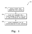
- Figure 1 is a flow diagram of one embodiment of a method 100 for generating a pseudo-random pattern of dots to be patterned on a surface in accordance with the present invention.
- step 102 surface input parameters for a surface are received.
- the surface input parameters for a surface are received at a programmable processor.
- Figure 2 is a pictorial diagram of a system comprising storage medium to cause a programmable processor to generate a pseudo-random pattern of dots.
- a system 130 includes a programmable processor 120 that receives the surface input parameters for the surface. The details for receiving surface input parameters are described below with reference to method 300 of Figure 3 .
- dot locations are selected for a pseudo-random pattern of dots on at least a portion of the surface.
- the selection of dot locations is based on the surface input parameters.
- the system 130 includes a programmable processor 120, which executes a program product, such as software 116 that is embodied on a storage medium 115, to select the dot locations for the pseudo-random pattern of dots to be patterned on the surface.
- a program product such as software 116 that is embodied on a storage medium 115
- pseudo-random pattern is a pattern that incorporates a randomness that overlays a systematic (non-random) structure. The details for selecting the dot locations in a pseudo-random pattern are described below with reference to method 400 of Figure 4 .
- coordinates for dot centers are output based on the dot locations.
- the programmable processor 120 outputs the coordinates for the dot centers.
- the dots When dots are placed at the coordinates for dot centers on the surface having a shape defined by the surface input parameters, the dots form a pseudo-random pattern on the at least a portion of the surface.
- Figure 3 is a flow diagram of one embodiment of a method 300 for receiving surface input parameters in accordance with the present invention.
- the method 300 is implemented by the system 130 of Figure 2 .
- step 302 surface input parameters are received for a surface having a known shape.
- the surface input parameters mathematically describe the known shape with reference to a known coordinate system.
- the programmable processor 120 receives the surface input parameters from a user via a user input interface 121 to the system 130.
- the known shape is a sphere.
- the programmable processor 120 receives surface input parameters for a spherical surface. At least a portion of the surface input parameters for the spherical surface includes a radius of the spherical surface.
- the known shape is a cylindrical surface.
- the programmable processor 120 receives surface input parameters for a cylindrical surface. At least a portion of the surface input parameters includes a radius of the cylindrical surface and a length of the cylindrical surface.
- the known shape is a flat surface.
- the programmable processor 120 receives surface input parameters for a flat surface. At least a portion of the surface input parameters includes at least one length of the flat surface, at least one width of the flat surface, a perpendicular distance from a center to a side, and/or a distance from a center to a vertex. If the flat surface is rectangular, only one length, and one width are required. If the flat surface is a polygon, then the lengths of the edges of the polygon, a perpendicular distance from a center to a side, and/or a distance from a center to a vertex are required.
- the known shape is a combination of at least two of a spherical surface, a cylindrical surface, and a flat surface.
- the programmable processor 120 receives surface input parameters that include at least two of a radius of the spherical surface, a radius of the cylindrical surface, a length of the cylindrical surface, at least one length of the flat surface, at least one width of the flat surface, a perpendicular distance from a center to a side, and/or a distance from a center to a vertex.
- the programmable processor 120 receives surface input parameters that mathematically describe the surfaces that conjoin unlike-surface shapes with reference to a known coordinate system.
- a selected cell area is received.
- the programmable processor 120 receives the selected cell area from a user via the user input interface 121.
- the selected cell area is 0.125 square inches for a sphere having a radius of 5 inches.
- Figure 4 is a flow diagram of one embodiment of a method 400 for selecting dot locations in accordance with the present invention.
- the method 300 is implemented by the system 130 of Figure 2 .
- the surface having the known shape is divided into an integral number of cells, each cell including a non-overlapping cell area approximately equal to the selected cell area.
- the known shape is a spherical shape
- a tessellation approximation is performed for the spherical surface to divide the spherical surface area into an integral number of cells, each cell including a non-overlapping cell area approximately equal to the selected cell area.
- the known shape is a cylindrical shape
- the cylindrical surface is divided into an integral number of cells, each cell including a non-overlapping cell area approximately equal to the selected cell area.
- the known shape is a flat surface
- the flat surface is divided into an integral number of cells, each cell including a non-overlapping cell area approximately equal to the selected cell area.
- one dot location is randomly selected in a respective one of the non-overlapping cell areas.
- a dot location is randomly selected for only a portion of the cells into which the known shape has been divided.
- a dot location is randomly selected for each one of the cells into which the known shape has been divided. Since the cell distribution is systematic (not random) and the dot position within the cell is random, the dot locations are in a pseudo-random pattern. As described above with reference to step 106 of method 100 in Figure 1 , when dots are placed at the output coordinates for dot centers on the surface of an object that has the known shape, the dots form a pseudo-random pattern on the surface of the object.
- the dots' locations were selected for only a portion of the surface, when dots are placed at the output coordinates for dot centers on the surface of an object having the known shape, the dots form a pseudo-random pattern on those portions of the surface of the object for which dot location have been selected.
- the minimum dot density is controlled to be at least 3 per field of view area for an imaging system in which the sphere is to be imaged.
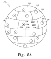
- Figures 5A and 5B are pictorial diagrams of a spherical surface including an integral number of cells upon which a pseudo-random pattern of dots has been patterned.
- Figure 5A is a pictorial diagram of a sphere 210 having a spherical surface 215 that is divided into an integral number of cells represented generally by the numeral 225.
- a pseudo-random pattern of dots represented generally by the numeral 231 has been patterned over the whole spherical surface 215.
- the spherical surface 215 is mathematically described as 4 ⁇ r 2 , where r is the radius of the sphere 210.
- the known coordinate system for the sphere 210 is a polar coordinate system having an origin located within the center of the sphere 210.
- Each dot 231 is centered on a dot center 230.
- the dot center 230 is a point in space on the spherical surface 215. As shown in Figure 5A , there is one dot center 230 located in each cell 225. Each dot center 230 is a point within the dot 231.
- the location of each dot center 230 on the surface 215 of the sphere can be mathematically described. For example, the dot center 230 can be described by polar coordinates using the polar coordinate system having an origin located within the center of the sphere 210.
- a dot 231 can be marked on the spherical surface 215, for example, by dropping an ink dot from an ink jet nozzle, at each of the mathematically described dot centers 230.
- Each cell 225 includes a non-overlapping cell area that includes the area bounded by the cell edges represented generally by the numeral 226.
- cell 225A shown centered in the view of the sphere 210 of Figure 5 , is bounded by edges 226 (A-D).
- edges 226 A-D
- the length of edge 226A and the length of edge 226C are approximately equal.
- the length of edge 226B and the length of edge 226D are approximately equal.
- the cell area is approximately the product of the length of edge 226A and the length of edge 226 B.
- Figure 5B is a pictorial diagram of a sphere 211 having a spherical surface 215 that is divided into an integral number of cells 225.
- the spherical surface 215 is mathematically described as 4 ⁇ r 2 , where r is the radius of the sphere 211.
- a pseudo-random pattern of dots 231 having dot centers 230 has been patterned over a portion of the spherical surface 215.
- the cells 225(A-F) are the portion of cells that includes a dot 231.
- a dot 231 can be marked on the spherical surface 215, for example, by dropping an ink dot from an ink jet nozzle, at each of the mathematically described dot centers 230 in the portion of cells 225 (A-F).
- the sphere 210 is a gas supported bearing for use in an inertial sensor assembly that is monitored by an optical imaging system that images the pseudo-random pattern on the surface 215 of the sphere 210.
- the sphere 211 is a gas supported bearing for use in an inertial sensor assembly that is monitored by an optical imaging system that images the pseudo-random pattern on the surface 215 of the sphere 211.
- Figure 6 is a pictorial diagram of an object 310 that has a complex surface 315 including an integral number of cells represented generally by the numeral 325 upon which a pseudo-random pattern of dots represented generally by the numeral 331 has been patterned. Each dot 331 is centered on a dot center 330.
- the dot center 330 is a point in space on the complex surface 315 of object 310 that is referenced to the three dimensional coordinate space shown by the X, Y, and Z vectors at the origin (0, 0, 0) that form a basis for the three dimensional space.
- the complex surface 315 includes a cylindrical surface 311 conjoined to a flat surface 312.
- the flat surface 312 is rectangularly shaped and is mathematically described by a length L fs and a width W fs .
- the cylindrical surface 311 is mathematically described by a radius R cyl and a length L cyl , which is equal to the length, L fs .
- Each cell 325 includes a non-overlapping cell area that includes the area bounded by the cell edges represented generally by the numeral 326.
- cell 325A shown at the far edge of the flat surface 312 in Figure 6 , is bounded by edges 326 (A-D).
- edges 326A and the length of edge 326C are approximately equal.
- the length of edge 326B and the length of edge 326D are approximately equal.
- the cell area of the cell 325A and all the other cells 325 on the complex surface 315 encompass a surface area or cell area that is approximately the product of the length of edge 326A and the length of edge 326B.
- each dot center 330 located in each cell 325.
- the location of each dot center 330 on the complex surface 315 can be mathematically described with reference to the X, Y, Z coordinate system.
- a dot 331 can be marked on the complex surface 315, for example, by dropping an ink dot from an ink jet nozzle, at each of the mathematically described dot centers 330.
- the dots 331 are only marked on the complex surface 315 in a portion of the cells 325.
- the object 310 that has a complex surface 315 is an object in an assembly line that is monitored by an optical imaging system that images the pseudo-random pattern on the complex surface 315.
- Exemplary software instructions that can be used for selecting dot locations for a pseudo-random pattern of dots on a spherical surface
Landscapes
- Physics & Mathematics (AREA)
- General Physics & Mathematics (AREA)
- Engineering & Computer Science (AREA)
- Radar, Positioning & Navigation (AREA)
- Remote Sensing (AREA)
- Image Processing (AREA)
- Image Analysis (AREA)
- Position Input By Displaying (AREA)
- Length Measuring Devices By Optical Means (AREA)
Applications Claiming Priority (1)
| Application Number | Priority Date | Filing Date | Title |
|---|---|---|---|
| US11/749,312 US7593829B2 (en) | 2007-05-16 | 2007-05-16 | Method for generating pseudo-random pattern designs for optical position determination systems |
Publications (3)
| Publication Number | Publication Date |
|---|---|
| EP1992907A2 true EP1992907A2 (de) | 2008-11-19 |
| EP1992907A3 EP1992907A3 (de) | 2009-12-09 |
| EP1992907B1 EP1992907B1 (de) | 2019-08-21 |
Family
ID=39705365
Family Applications (1)
| Application Number | Title | Priority Date | Filing Date |
|---|---|---|---|
| EP08156125.0A Ceased EP1992907B1 (de) | 2007-05-16 | 2008-05-13 | Verfahren zur Erstellung von Pseudozufallsstrukturentwürfen für optische Positionsbestimmungssysteme |
Country Status (2)
| Country | Link |
|---|---|
| US (1) | US7593829B2 (de) |
| EP (1) | EP1992907B1 (de) |
Families Citing this family (4)
| Publication number | Priority date | Publication date | Assignee | Title |
|---|---|---|---|---|
| US8068136B2 (en) * | 2007-05-16 | 2011-11-29 | Honeywell International Inc. | Method and system for determining angular position of an object |
| US8737685B2 (en) * | 2011-04-25 | 2014-05-27 | Honeywell International Inc. | Systems and methods for detecting the movement of an object |
| US8494221B2 (en) | 2011-04-28 | 2013-07-23 | Honeywell International Inc. | Inverse star tracker using psuedo-random overlapping circles |
| US20130094590A1 (en) * | 2011-10-12 | 2013-04-18 | Vixs Systems, Inc. | Video decoding device for extracting embedded metadata and methods for use therewith |
Citations (2)
| Publication number | Priority date | Publication date | Assignee | Title |
|---|---|---|---|---|
| US5396559A (en) | 1990-08-24 | 1995-03-07 | Mcgrew; Stephen P. | Anticounterfeiting method and device utilizing holograms and pseudorandom dot patterns |
| US20060058978A1 (en) | 2004-09-10 | 2006-03-16 | Honeywell International Inc. | Absolute position determination of an object using pattern recognition |
Family Cites Families (6)
| Publication number | Priority date | Publication date | Assignee | Title |
|---|---|---|---|---|
| JPH09130602A (ja) * | 1995-11-01 | 1997-05-16 | Ricoh Co Ltd | 画像処理装置 |
| JP3402138B2 (ja) * | 1996-09-27 | 2003-04-28 | 株式会社日立製作所 | 液晶表示装置 |
| AUPQ835100A0 (en) * | 2000-06-23 | 2000-07-20 | Bishop Innovation Limited | Position sensor |
| TW567392B (en) * | 2001-09-07 | 2003-12-21 | Nec Corp | Device for generating ragged pattern data in random arrangement, computer program, mask and manufacturing device, light reflection member manufacturing device, liquid crystal manufacturing device, liquid crystal display device, portable terminal device |
| JP4514132B2 (ja) * | 2004-05-28 | 2010-07-28 | 大日本スクリーン製造株式会社 | 網点画像生成用の閾値マトリクス生成方法、網点画像生成方法および装置、並びに閾値マトリクス |
| US20080144111A1 (en) * | 2006-10-20 | 2008-06-19 | Cheng-Tai Lee | Generating random and density controllable dot patterns method |
-
2007
- 2007-05-16 US US11/749,312 patent/US7593829B2/en active Active
-
2008
- 2008-05-13 EP EP08156125.0A patent/EP1992907B1/de not_active Ceased
Patent Citations (2)
| Publication number | Priority date | Publication date | Assignee | Title |
|---|---|---|---|---|
| US5396559A (en) | 1990-08-24 | 1995-03-07 | Mcgrew; Stephen P. | Anticounterfeiting method and device utilizing holograms and pseudorandom dot patterns |
| US20060058978A1 (en) | 2004-09-10 | 2006-03-16 | Honeywell International Inc. | Absolute position determination of an object using pattern recognition |
Also Published As
| Publication number | Publication date |
|---|---|
| US7593829B2 (en) | 2009-09-22 |
| EP1992907A3 (de) | 2009-12-09 |
| EP1992907B1 (de) | 2019-08-21 |
| US20080288207A1 (en) | 2008-11-20 |
Similar Documents
| Publication | Publication Date | Title |
|---|---|---|
| EP1992908A2 (de) | Verfahren und System zur Bestimmung der Winkelposition eines Objektes | |
| CN105222788B (zh) | 基于特征匹配的飞行器航路偏移误差的自校正方法 | |
| CN106525074B (zh) | 一种云台漂移的补偿方法、装置、云台和无人机 | |
| CN110849331B (zh) | 基于三维点云数据库模型的单目视觉测量与地面试验方法 | |
| Kelly et al. | Visual-inertial simultaneous localization, mapping and sensor-to-sensor self-calibration | |
| US20120262455A1 (en) | Three-dimensional measurement apparatus, model generation apparatus, processing method thereof, and non-transitory computer-readable storage medium | |
| CN114509071B (zh) | 一种风洞试验模型姿态测量方法 | |
| CN113022898A (zh) | 弱引力环境柔性附着系统状态估计方法 | |
| EP1992907A2 (de) | Verfahren zur Erstellung von Pseudozufallsstrukturentwürfen für optische Positionsbestimmungssysteme | |
| CN105526951B (zh) | 一种星敏感器原始观测数据预处理方法及系统 | |
| CN115544648B (zh) | 一种基于天基观测的卫星轨道确定方法和装置 | |
| CN115205399A (zh) | 不共视多目相机标定方法、装置、机器人及存储介质 | |
| CN113052974B (zh) | 物体三维表面的重建方法和装置 | |
| CN107861919A (zh) | 一种星敏感器定姿星矢量权值实时分配方法 | |
| Enright et al. | Rolling shutter compensation for star trackers | |
| CN109344785A (zh) | 一种在深空自主光学导航中的高精度的行星中心定位方法 | |
| Wu et al. | On-orbit calibration method for star sensors based on microvariation in intrinsic parameters | |
| CN114252088A (zh) | 基于平行光管的星图匹配半实物验证方法 | |
| CN114758011A (zh) | 融合离线标定结果的变焦相机在线标定方法 | |
| CN119796529B (zh) | 一种遥感卫星对空间目标指向姿态的规划控制方法及装置 | |
| KR20050105369A (ko) | 별센서 자세결정 시험장치 및 별센서 자세결정 시험장치의가상 별자리 투영방법 | |
| CN114111782A (zh) | 柔性着陆器状态表征与估计方法 | |
| CN105004315B (zh) | 低动态水平/方位角在线测量装置及测量方法 | |
| CN111780745A (zh) | 一种面向深空探测光学导航的短弧椭圆拟合优化方法 | |
| US20030016861A1 (en) | Apparatus for constituting three-dimensional model |
Legal Events
| Date | Code | Title | Description |
|---|---|---|---|
| PUAI | Public reference made under article 153(3) epc to a published international application that has entered the european phase |
Free format text: ORIGINAL CODE: 0009012 |
|
| 17P | Request for examination filed |
Effective date: 20080513 |
|
| AK | Designated contracting states |
Kind code of ref document: A2 Designated state(s): AT BE BG CH CY CZ DE DK EE ES FI FR GB GR HR HU IE IS IT LI LT LU LV MC MT NL NO PL PT RO SE SI SK TR |
|
| AX | Request for extension of the european patent |
Extension state: AL BA MK RS |
|
| PUAL | Search report despatched |
Free format text: ORIGINAL CODE: 0009013 |
|
| AK | Designated contracting states |
Kind code of ref document: A3 Designated state(s): AT BE BG CH CY CZ DE DK EE ES FI FR GB GR HR HU IE IS IT LI LT LU LV MC MT NL NO PL PT RO SE SI SK TR |
|
| AX | Request for extension of the european patent |
Extension state: AL BA MK RS |
|
| RIC1 | Information provided on ipc code assigned before grant |
Ipc: G01C 15/00 20060101ALI20091030BHEP Ipc: G01B 11/26 20060101AFI20080827BHEP |
|
| 17Q | First examination report despatched |
Effective date: 20091118 |
|
| AKX | Designation fees paid |
Designated state(s): DE FR GB |
|
| RAP1 | Party data changed (applicant data changed or rights of an application transferred) |
Owner name: HONEYWELL INTERNATIONAL INC. |
|
| GRAP | Despatch of communication of intention to grant a patent |
Free format text: ORIGINAL CODE: EPIDOSNIGR1 |
|
| INTG | Intention to grant announced |
Effective date: 20190410 |
|
| GRAS | Grant fee paid |
Free format text: ORIGINAL CODE: EPIDOSNIGR3 |
|
| GRAA | (expected) grant |
Free format text: ORIGINAL CODE: 0009210 |
|
| AK | Designated contracting states |
Kind code of ref document: B1 Designated state(s): DE FR GB |
|
| REG | Reference to a national code |
Ref country code: GB Ref legal event code: FG4D |
|
| REG | Reference to a national code |
Ref country code: DE Ref legal event code: R096 Ref document number: 602008060956 Country of ref document: DE |
|
| REG | Reference to a national code |
Ref country code: DE Ref legal event code: R097 Ref document number: 602008060956 Country of ref document: DE |
|
| PLBE | No opposition filed within time limit |
Free format text: ORIGINAL CODE: 0009261 |
|
| STAA | Information on the status of an ep patent application or granted ep patent |
Free format text: STATUS: NO OPPOSITION FILED WITHIN TIME LIMIT |
|
| 26N | No opposition filed |
Effective date: 20200603 |
|
| PGFP | Annual fee paid to national office [announced via postgrant information from national office to epo] |
Ref country code: DE Payment date: 20210527 Year of fee payment: 14 Ref country code: FR Payment date: 20210526 Year of fee payment: 14 |
|
| PGFP | Annual fee paid to national office [announced via postgrant information from national office to epo] |
Ref country code: GB Payment date: 20210526 Year of fee payment: 14 |
|
| REG | Reference to a national code |
Ref country code: DE Ref legal event code: R119 Ref document number: 602008060956 Country of ref document: DE |
|
| GBPC | Gb: european patent ceased through non-payment of renewal fee |
Effective date: 20220513 |
|
| PG25 | Lapsed in a contracting state [announced via postgrant information from national office to epo] |
Ref country code: FR Free format text: LAPSE BECAUSE OF NON-PAYMENT OF DUE FEES Effective date: 20220531 |
|
| PG25 | Lapsed in a contracting state [announced via postgrant information from national office to epo] |
Ref country code: GB Free format text: LAPSE BECAUSE OF NON-PAYMENT OF DUE FEES Effective date: 20220513 Ref country code: DE Free format text: LAPSE BECAUSE OF NON-PAYMENT OF DUE FEES Effective date: 20221201 |
|
| P01 | Opt-out of the competence of the unified patent court (upc) registered |
Effective date: 20230525 |