EP1992831A1 - Unité de synchronisation pour boîte de vitesses d'un véhicule à moteur - Google Patents
Unité de synchronisation pour boîte de vitesses d'un véhicule à moteur Download PDFInfo
- Publication number
- EP1992831A1 EP1992831A1 EP08156059A EP08156059A EP1992831A1 EP 1992831 A1 EP1992831 A1 EP 1992831A1 EP 08156059 A EP08156059 A EP 08156059A EP 08156059 A EP08156059 A EP 08156059A EP 1992831 A1 EP1992831 A1 EP 1992831A1
- Authority
- EP
- European Patent Office
- Prior art keywords
- gear
- synchronizing
- synchronizing ring
- toothing
- teeth
- Prior art date
- Legal status (The legal status is an assumption and is not a legal conclusion. Google has not performed a legal analysis and makes no representation as to the accuracy of the status listed.)
- Granted
Links
- 230000000717 retained effect Effects 0.000 claims abstract 2
- 230000008878 coupling Effects 0.000 claims description 18
- 238000010168 coupling process Methods 0.000 claims description 18
- 238000005859 coupling reaction Methods 0.000 claims description 18
- 230000005540 biological transmission Effects 0.000 claims 1
- 239000002783 friction material Substances 0.000 description 2
- 230000007935 neutral effect Effects 0.000 description 2
- 238000010276 construction Methods 0.000 description 1
- 230000001419 dependent effect Effects 0.000 description 1
- 238000006073 displacement reaction Methods 0.000 description 1
- 230000014759 maintenance of location Effects 0.000 description 1
- 230000035939 shock Effects 0.000 description 1
Images


Classifications
-
- F—MECHANICAL ENGINEERING; LIGHTING; HEATING; WEAPONS; BLASTING
- F16—ENGINEERING ELEMENTS AND UNITS; GENERAL MEASURES FOR PRODUCING AND MAINTAINING EFFECTIVE FUNCTIONING OF MACHINES OR INSTALLATIONS; THERMAL INSULATION IN GENERAL
- F16D—COUPLINGS FOR TRANSMITTING ROTATION; CLUTCHES; BRAKES
- F16D23/00—Details of mechanically-actuated clutches not specific for one distinct type
- F16D23/02—Arrangements for synchronisation, also for power-operated clutches
- F16D23/04—Arrangements for synchronisation, also for power-operated clutches with an additional friction clutch
- F16D23/06—Arrangements for synchronisation, also for power-operated clutches with an additional friction clutch and a blocking mechanism preventing the engagement of the main clutch prior to synchronisation
- F16D2023/0656—Details of the tooth structure; Arrangements of teeth
Definitions
- the present invention refers to a synchronizing unit for a gearbox of a motor vehicle, as specified in the preamble of Claim 1.
- Synchronizing units of the above-defined type are used in motor-vehicle gearboxes to couple for rotation with each other a pair of adjacent gears which are mounted on the same shaft of the gearbox and rotate at different speeds in the uncoupled condition, only after the two gears have been brought to the same rotational speed, whereby the engagement manoeuvre between the engagement toothings of the two gears can take place without unacceptable shocks and loads.
- a synchronizing unit for a gearbox of a motor vehicle comprises a first, axially stationary gear 10 (hereinafter simply referred to as stationary gear), a second, axially movable gear 12 (hereinafter simply referred to as sliding gear) mounted adjacent to the stationary gear 10 on a same shaft 14 of the gearbox, and a synchronizing ring 16 interposed between the stationary gear 10 and the sliding gear 12.
- the stationary gear 10 has an inner engagement toothing 18 adapted to mesh with a corresponding outer engagement toothing 20 of the sliding gear 12 in order to ensure that the two gears 10 and 12 are coupled for rotation with each other.
- the synchronizing unit further comprises a spring 32 axially interposed between the synchronizing ring 16 and the sliding gear 12 to urge the synchronizing ring 16 towards the stationary gear 10.
- the end-of-travel position of the synchronizing ring 16 on the side of the stationary gear 10 is defined by a retaining circlip 34 fitted onto a hub portion 36 of the sliding gear 12 near the outer engagement toothing 20.
- the hub portion 36 of the sliding gear 12 has a notch 38 in which a control member 40 for controlling the sliding movement of that gear engages.
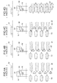
- Figure 4A shows the synchronizing unit in the neutral initial condition, in which the engagement toothings 18 and 20 of the two gears 10 and 12 do not mesh with each other and the coupling conical surfaces 24 and 30 of the synchronizing ring 16 and of the stationary gear 10 are not in abutment with each other.
- Figure 4B shows the synchronizing unit in the start-of-synchronization condition, in which the coupling conical surfaces 24 and 30 of the synchronizing ring 16 and of the stationary gear 10 come into abutment with each other and the spring 32 is compressed as a result of the axial movement of the sliding gear 12 towards the stationary gear 10.
- the friction force acting on the coupling conical surfaces 24 and 30 due to the axial force exerted by the spring 32 and by the inclined front surfaces of the engagement toothings 20 and 22 allows to generate a synchronizing torque between the synchronizing ring 16 and the stationary gear 10 until a condition is reached in which these two components have the same angular speed and are therefore in relative rest.
- the synchronizing ring 16 rotates due to the different angular speeds of the two gears 10 and 12 until the inclined front surfaces of the engagement toothing 22 thereof are brought into abutment against the inclined front surfaces of the engagement toothing 20 of the sliding gear 12.
- the engagement toothing 20 of the sliding gear 12 cannot therefore move towards the engagement toothing 18 of the stationary gear 10, but remains in front abutment against the engagement toothing 22 of the synchronizing ring 16.
- Figure 4D finally shows the end-of-engagement condition, in which the engagement toothings 18 and 20 of the stationary gear 10 and of the sliding gear 12, respectively, mesh with each other.
- the synchronizing ring 16 travels along the same path as the one of the engagement phase, but in the opposite direction, under the action of the spring 32, sliding along the engagement toothing 20 of the sliding gear 12 until it gets back into abutment against the retaining circlip 34.
- the above-described known solution has some shortcomings. First of all, it does not allow to have an outright presynchronization phase. Secondly, the angular or rotational travel of the synchronizing ring relative to the engagement toothing of the sliding gear at the beginning of the synchronization phase is not univocal. Finally, the spring keeps on with exerting an axial force on the synchronizing ring also during the engagement phase, thereby making the alignment of the engagement toothings 20 and 22 difficult, even though it is no more necessary to generate a synchronizing torque by means of the friction between the coupling conical surfaces.
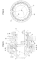
- a synchronizing unit for a gearbox of a motor vehicle comprises a first, axially stationary gear 10 (hereinafter simply referred to as stationary gear), a second, axially movable gear 12 (hereinafter simply referred to as sliding gear) mounted adjacent to the stationary gear 10 on a same shaft 14 of the gearbox, and a synchronizing ring 16 interposed between the stationary gear 10 and the sliding gear 12.
- the two gears might also be inverted, in that the gear 10 might be the sliding gear and the gear 12 the stationary one, as it suffices to have a relative axial movement between the two gears 10 and 12 for the operation of the synchronizing unit.
- the two gears 10 and 12 are idly mounted on the shaft 14 by means of respective bearings 11 and 13, such as for example needle bearings.
- the stationary gear 10 has an inner engagement toothing 18 adapted to mesh with a corresponding outer engagement toothing 20 of the sliding gear 12 to ensure that the two gears 10 and 12 are coupled for rotation with each other.
- the synchronizing ring 16 has an inner engagement toothing 22 intended to mesh with the outer engagement toothing 20 of the sliding gear 12 in order to drivingly connect the synchronizing ring 16 for rotation with the sliding gear 12.
- Teeth 23 of greater width which have the function of stopping the angular movement of the synchronizing ring and are therefore referred to hereinafter as stopping teeth, are interposed between the teeth of the inner engagement toothing 22 of the synchronizing ring 16.
- three stopping teeth 23 arranged at 120 degrees are provided.
- the tangential play between the stopping teeth 23 of the synchronizing ring 16 and the corresponding pairs of engagement teeth 20 of the sliding gear 12 is greater than the tangential play between the engagement teeth 22 of the synchronizing ring 16 and the engagement teeth 20 of the sliding gear 12.
- the stopping teeth 23 axially project beyond the teeth of the inner engagement toothing 22 of the synchronizing ring 16 towards the sliding gear 12 and have a groove 25 located in an axially middle position and extending in a plane perpendicular to the axis of the synchronizing ring 16.
- the synchronizing unit further comprises a presynchronization circlip 27 received in the grooves 25 of the stopping teeth 23 so as to be axially restrained to the synchronizing ring 16, as well as a retaining circlip 34 fitted onto the annular end portion 28 of the stationary gear 10 to axially retain the synchronizing ring 16 on the side of the sliding gear 12.
- the outer engagement toothing 20 of the sliding gear 12 forms a radial projection 29 of trapezoidal axial section, which acts on the presynchronization circlip 27 as a cam to bring about the presynchronization phase, as will be better explained further on.
- a hub portion 36 of the sliding gear 12 has a groove 38 in which a control member (not shown) arranged to control the sliding movement of that gear engages.
- Figure 7B shows the synchronizing unit in the start-of-presynchronization condition, in which a ramp-like inclined surface 29a of the radial projection 29 abuts with the presynchronization circlip 27 as a result of the axial movement of the sliding gear 12 towards the stationary gear 10 and tends both to urge it axially towards the stationary gear 10 and to expand it radially.
- the presynchronization circlip 27 axially urges the synchronizing ring 16 towards the stationary gear 10 and thus brings the coupling conical surfaces 24 and 30 of the synchronizing ring 16 and of the stationary gear 10 into abutment with each other.
- Figure 7C shows the synchronizing unit in the end-of-presynchronization condition, in which the inclined front surfaces of the engagement toothing 22 of the synchronizing ring 16 come into abutment with the corresponding inclined front surfaces of the engagement toothing 20 of the sliding gear 12a as a result of a further axial displacement of the sliding gear 12 towards the stationary gear 10.
- the outright synchronization phase thus begins, in which phase the engagement toothing 20 of the sliding gear 12 cannot move towards the engagement toothing 18 of the stationary gear 10, but remains in front abutment against the engagement toothing 22 of the synchronizing ring 16.
- the friction force acting on the coupling conical surfaces 24 and 30 due to the axial force exerted by the inclined front surfaces of the engagement toothings 20 and 22 makes it possible to generate a synchronizing torque between the synchronizing ring 16 and the stationary gear 10 until a condition is reached in which these two components have the same angular speed and are therefore in relative rest.
- the presynchronization circlip 27 is located at the upper edge of the ramp-like inclined surface 29a of the radial projection 29.
- the synchronizing ring 16 rotates in the direction opposite to the first one, thus allowing the outer engagement toothing 20 of the sliding gear 12 to move again towards the inner engagement toothing 18 of the stationary gear 10, thereby coming into alignment and engagement with this latter.
- the presynchronization circlip 27 is no more in abutment with the ramp-like inclined surface 29a of the radial projection 29, but slides on a flat upper portion 29b of this latter. Accordingly, the presynchronization circlip 27 does not stress the synchronizing ring 16 any more and hence does not impede the alignment between the engagement toothings 18 and 20 of the two gears 10 and 12.
- Figure 7E shows the end-of-engagement condition, in which the engagement toothings 20 and 22 of the stationary gear 10 and of the sliding gear 12 mesh with each other.
- the presynchronization circlip 27 follows in the opposite direction the same path as the one followed during the engagement operation, sliding along the outline of the radial projection 29.
- the retaining circlip 25 ensures axial retention of the synchronizing ring 16 and hence of the groove 25 receiving the presynchronization circlip 27.
- a synchronizing unit makes it possible to obtain an outright presynchronization phase, to ensure a univocal angular movement (rotation) of the synchronizing ring relative to the engagement toothing of the sliding gear and to prevent the synchronizing ring from being axially loaded during the engagement phase.
Landscapes
- Engineering & Computer Science (AREA)
- General Engineering & Computer Science (AREA)
- Mechanical Engineering (AREA)
- Mechanical Operated Clutches (AREA)
- Gears, Cams (AREA)
- Gear-Shifting Mechanisms (AREA)
- Control Of Ac Motors In General (AREA)
- Control Of Electric Motors In General (AREA)
Applications Claiming Priority (1)
| Application Number | Priority Date | Filing Date | Title |
|---|---|---|---|
| IT000331A ITTO20070331A1 (it) | 2007-05-14 | 2007-05-14 | Gruppo sincronizzatore per un cambio di velocita' di un autoveicolo |
Publications (2)
| Publication Number | Publication Date |
|---|---|
| EP1992831A1 true EP1992831A1 (fr) | 2008-11-19 |
| EP1992831B1 EP1992831B1 (fr) | 2010-05-12 |
Family
ID=39684315
Family Applications (1)
| Application Number | Title | Priority Date | Filing Date |
|---|---|---|---|
| EP08156059A Active EP1992831B1 (fr) | 2007-05-14 | 2008-05-13 | Unité de synchronisation pour boîte de vitesses d'un véhicule à moteur |
Country Status (5)
| Country | Link |
|---|---|
| EP (1) | EP1992831B1 (fr) |
| AT (1) | ATE467773T1 (fr) |
| DE (1) | DE602008001198D1 (fr) |
| ES (1) | ES2346109T3 (fr) |
| IT (1) | ITTO20070331A1 (fr) |
Cited By (3)
| Publication number | Priority date | Publication date | Assignee | Title |
|---|---|---|---|---|
| WO2014182446A1 (fr) * | 2013-05-08 | 2014-11-13 | Schaeffler Technologies Gmbh & Co. Kg | Dispositif de coupure de transfert d'energie rotative |
| CN105042001A (zh) * | 2015-08-25 | 2015-11-11 | 昆山德拉特兰传动科技有限公司 | 具有唯一相位角的换挡机构 |
| WO2019185896A1 (fr) | 2018-03-29 | 2019-10-03 | OERLIKON FRICTION SYSTEMS (GERMANY) GmbH | Conception de synchroniseur optimisée dans l'espace |
Citations (5)
| Publication number | Priority date | Publication date | Assignee | Title |
|---|---|---|---|---|
| US4736643A (en) * | 1986-03-07 | 1988-04-12 | Eaton Corporation | Blocked jaw clutch assembly |
| EP0288718A1 (fr) * | 1987-04-29 | 1988-11-02 | Ford-Werke Aktiengesellschaft | Dispositif de synchronisation pour boîte de vitesse, notamment pour automobiles |
| EP0821175A1 (fr) * | 1996-07-24 | 1998-01-28 | Valeo | Bague de synchronisation pour un synchroniseur de boíte de vitesses |
| EP1072812A1 (fr) * | 1999-07-27 | 2001-01-31 | Peugeot Citroen Automobiles SA | Ensemble synchroniseur de marche arrière pour une transmission d'un véhicule automobile |
| US6250446B1 (en) * | 1999-11-02 | 2001-06-26 | Ford Global Tech., Inc. | Clutch assembly |
-
2007
- 2007-05-14 IT IT000331A patent/ITTO20070331A1/it unknown
-
2008
- 2008-05-13 AT AT08156059T patent/ATE467773T1/de not_active IP Right Cessation
- 2008-05-13 EP EP08156059A patent/EP1992831B1/fr active Active
- 2008-05-13 DE DE602008001198T patent/DE602008001198D1/de active Active
- 2008-05-13 ES ES08156059T patent/ES2346109T3/es active Active
Patent Citations (5)
| Publication number | Priority date | Publication date | Assignee | Title |
|---|---|---|---|---|
| US4736643A (en) * | 1986-03-07 | 1988-04-12 | Eaton Corporation | Blocked jaw clutch assembly |
| EP0288718A1 (fr) * | 1987-04-29 | 1988-11-02 | Ford-Werke Aktiengesellschaft | Dispositif de synchronisation pour boîte de vitesse, notamment pour automobiles |
| EP0821175A1 (fr) * | 1996-07-24 | 1998-01-28 | Valeo | Bague de synchronisation pour un synchroniseur de boíte de vitesses |
| EP1072812A1 (fr) * | 1999-07-27 | 2001-01-31 | Peugeot Citroen Automobiles SA | Ensemble synchroniseur de marche arrière pour une transmission d'un véhicule automobile |
| US6250446B1 (en) * | 1999-11-02 | 2001-06-26 | Ford Global Tech., Inc. | Clutch assembly |
Cited By (3)
| Publication number | Priority date | Publication date | Assignee | Title |
|---|---|---|---|---|
| WO2014182446A1 (fr) * | 2013-05-08 | 2014-11-13 | Schaeffler Technologies Gmbh & Co. Kg | Dispositif de coupure de transfert d'energie rotative |
| CN105042001A (zh) * | 2015-08-25 | 2015-11-11 | 昆山德拉特兰传动科技有限公司 | 具有唯一相位角的换挡机构 |
| WO2019185896A1 (fr) | 2018-03-29 | 2019-10-03 | OERLIKON FRICTION SYSTEMS (GERMANY) GmbH | Conception de synchroniseur optimisée dans l'espace |
Also Published As
| Publication number | Publication date |
|---|---|
| ITTO20070331A1 (it) | 2008-11-15 |
| EP1992831B1 (fr) | 2010-05-12 |
| ATE467773T1 (de) | 2010-05-15 |
| ES2346109T3 (es) | 2010-10-08 |
| DE602008001198D1 (de) | 2010-06-24 |
Similar Documents
| Publication | Publication Date | Title |
|---|---|---|
| EP0652385B1 (fr) | Assemblage d'embrayage avec synchroniseur pour transmission à vitesses multiples | |
| US20120006643A1 (en) | Double-acting synchronizer | |
| CN106795950B (zh) | 变速箱的改进 | |
| US10935082B2 (en) | Synchronizer device for a manual transmission | |
| US20110214522A1 (en) | Shifting clutch | |
| US9341240B2 (en) | Shift device with synchronizer | |
| KR20090127141A (ko) | 클러치 조립체 | |
| PL130974B1 (en) | Synchro-mesh gear of locking type for changeable transmission gears | |
| JPH094653A (ja) | 自己増力式同期クラッチ | |
| CN104132129A (zh) | 用于机动车辆变速器的换档装置 | |
| US9194443B2 (en) | Synchronising device between two revolving components | |
| JPH07208496A (ja) | 同期クラッチ機構 | |
| US8245590B2 (en) | Device for transmitting a torque | |
| JP2001512219A (ja) | クラッチ | |
| EP1992831B1 (fr) | Unité de synchronisation pour boîte de vitesses d'un véhicule à moteur | |
| JPH04228929A (ja) | ギヤーカプラー | |
| US8869963B2 (en) | Arrangement for shifting a gearbox | |
| US4623054A (en) | Dual reversed cone synchronizing clutch | |
| US20070084692A1 (en) | Clutch device for an automobile transmission, in particular for a form-locking and a frictionally-engaging clutch | |
| EP2677189A1 (fr) | Boîte de vitesses d'un véhicule et véhicule comportant une telle boîte de vitesses | |
| KR100309686B1 (ko) | 자기에너자이징을지닌동기화기 | |
| CN111417790B (zh) | 爪式换挡机构 | |
| CZ307443B6 (cs) | Řadicí spojka | |
| EP0976942B1 (fr) | Embrayage synchronisé pour la boíte de vitesse d'une véhicule | |
| KR102496249B1 (ko) | 변속기구 |
Legal Events
| Date | Code | Title | Description |
|---|---|---|---|
| PUAI | Public reference made under article 153(3) epc to a published international application that has entered the european phase |
Free format text: ORIGINAL CODE: 0009012 |
|
| AK | Designated contracting states |
Kind code of ref document: A1 Designated state(s): AT BE BG CH CY CZ DE DK EE ES FI FR GB GR HR HU IE IS IT LI LT LU LV MC MT NL NO PL PT RO SE SI SK TR |
|
| AX | Request for extension of the european patent |
Extension state: AL BA MK RS |
|
| 17P | Request for examination filed |
Effective date: 20090515 |
|
| AKX | Designation fees paid |
Designated state(s): AT BE BG CH CY CZ DE DK EE ES FI FR GB GR HR HU IE IS IT LI LT LU LV MC MT NL NO PL PT RO SE SI SK TR |
|
| GRAP | Despatch of communication of intention to grant a patent |
Free format text: ORIGINAL CODE: EPIDOSNIGR1 |
|
| GRAS | Grant fee paid |
Free format text: ORIGINAL CODE: EPIDOSNIGR3 |
|
| GRAA | (expected) grant |
Free format text: ORIGINAL CODE: 0009210 |
|
| AK | Designated contracting states |
Kind code of ref document: B1 Designated state(s): AT BE BG CH CY CZ DE DK EE ES FI FR GB GR HR HU IE IS IT LI LT LU LV MC MT NL NO PL PT RO SE SI SK TR |
|
| REG | Reference to a national code |
Ref country code: GB Ref legal event code: FG4D |
|
| REG | Reference to a national code |
Ref country code: CH Ref legal event code: EP |
|
| REG | Reference to a national code |
Ref country code: IE Ref legal event code: FG4D |
|
| REF | Corresponds to: |
Ref document number: 602008001198 Country of ref document: DE Date of ref document: 20100624 Kind code of ref document: P |
|
| REG | Reference to a national code |
Ref country code: NL Ref legal event code: VDEP Effective date: 20100512 |
|
| REG | Reference to a national code |
Ref country code: ES Ref legal event code: FG2A Ref document number: 2346109 Country of ref document: ES Kind code of ref document: T3 |
|
| LTIE | Lt: invalidation of european patent or patent extension |
Effective date: 20100512 |
|
| PG25 | Lapsed in a contracting state [announced via postgrant information from national office to epo] |
Ref country code: NO Free format text: LAPSE BECAUSE OF FAILURE TO SUBMIT A TRANSLATION OF THE DESCRIPTION OR TO PAY THE FEE WITHIN THE PRESCRIBED TIME-LIMIT Effective date: 20100812 Ref country code: SE Free format text: LAPSE BECAUSE OF FAILURE TO SUBMIT A TRANSLATION OF THE DESCRIPTION OR TO PAY THE FEE WITHIN THE PRESCRIBED TIME-LIMIT Effective date: 20100512 Ref country code: LT Free format text: LAPSE BECAUSE OF FAILURE TO SUBMIT A TRANSLATION OF THE DESCRIPTION OR TO PAY THE FEE WITHIN THE PRESCRIBED TIME-LIMIT Effective date: 20100512 Ref country code: NL Free format text: LAPSE BECAUSE OF FAILURE TO SUBMIT A TRANSLATION OF THE DESCRIPTION OR TO PAY THE FEE WITHIN THE PRESCRIBED TIME-LIMIT Effective date: 20100512 |
|
| PG25 | Lapsed in a contracting state [announced via postgrant information from national office to epo] |
Ref country code: FI Free format text: LAPSE BECAUSE OF FAILURE TO SUBMIT A TRANSLATION OF THE DESCRIPTION OR TO PAY THE FEE WITHIN THE PRESCRIBED TIME-LIMIT Effective date: 20100512 Ref country code: SI Free format text: LAPSE BECAUSE OF FAILURE TO SUBMIT A TRANSLATION OF THE DESCRIPTION OR TO PAY THE FEE WITHIN THE PRESCRIBED TIME-LIMIT Effective date: 20100512 Ref country code: LV Free format text: LAPSE BECAUSE OF FAILURE TO SUBMIT A TRANSLATION OF THE DESCRIPTION OR TO PAY THE FEE WITHIN THE PRESCRIBED TIME-LIMIT Effective date: 20100512 Ref country code: IS Free format text: LAPSE BECAUSE OF FAILURE TO SUBMIT A TRANSLATION OF THE DESCRIPTION OR TO PAY THE FEE WITHIN THE PRESCRIBED TIME-LIMIT Effective date: 20100912 Ref country code: HR Free format text: LAPSE BECAUSE OF FAILURE TO SUBMIT A TRANSLATION OF THE DESCRIPTION OR TO PAY THE FEE WITHIN THE PRESCRIBED TIME-LIMIT Effective date: 20100512 Ref country code: AT Free format text: LAPSE BECAUSE OF FAILURE TO SUBMIT A TRANSLATION OF THE DESCRIPTION OR TO PAY THE FEE WITHIN THE PRESCRIBED TIME-LIMIT Effective date: 20100512 |
|
| PG25 | Lapsed in a contracting state [announced via postgrant information from national office to epo] |
Ref country code: CY Free format text: LAPSE BECAUSE OF FAILURE TO SUBMIT A TRANSLATION OF THE DESCRIPTION OR TO PAY THE FEE WITHIN THE PRESCRIBED TIME-LIMIT Effective date: 20100602 Ref country code: MC Free format text: LAPSE BECAUSE OF NON-PAYMENT OF DUE FEES Effective date: 20100531 Ref country code: PL Free format text: LAPSE BECAUSE OF FAILURE TO SUBMIT A TRANSLATION OF THE DESCRIPTION OR TO PAY THE FEE WITHIN THE PRESCRIBED TIME-LIMIT Effective date: 20100512 |
|
| PG25 | Lapsed in a contracting state [announced via postgrant information from national office to epo] |
Ref country code: EE Free format text: LAPSE BECAUSE OF FAILURE TO SUBMIT A TRANSLATION OF THE DESCRIPTION OR TO PAY THE FEE WITHIN THE PRESCRIBED TIME-LIMIT Effective date: 20100512 Ref country code: DK Free format text: LAPSE BECAUSE OF FAILURE TO SUBMIT A TRANSLATION OF THE DESCRIPTION OR TO PAY THE FEE WITHIN THE PRESCRIBED TIME-LIMIT Effective date: 20100512 |
|
| PG25 | Lapsed in a contracting state [announced via postgrant information from national office to epo] |
Ref country code: BE Free format text: LAPSE BECAUSE OF FAILURE TO SUBMIT A TRANSLATION OF THE DESCRIPTION OR TO PAY THE FEE WITHIN THE PRESCRIBED TIME-LIMIT Effective date: 20100512 Ref country code: SK Free format text: LAPSE BECAUSE OF FAILURE TO SUBMIT A TRANSLATION OF THE DESCRIPTION OR TO PAY THE FEE WITHIN THE PRESCRIBED TIME-LIMIT Effective date: 20100512 Ref country code: RO Free format text: LAPSE BECAUSE OF FAILURE TO SUBMIT A TRANSLATION OF THE DESCRIPTION OR TO PAY THE FEE WITHIN THE PRESCRIBED TIME-LIMIT Effective date: 20100512 Ref country code: CZ Free format text: LAPSE BECAUSE OF FAILURE TO SUBMIT A TRANSLATION OF THE DESCRIPTION OR TO PAY THE FEE WITHIN THE PRESCRIBED TIME-LIMIT Effective date: 20100512 |
|
| PLBE | No opposition filed within time limit |
Free format text: ORIGINAL CODE: 0009261 |
|
| STAA | Information on the status of an ep patent application or granted ep patent |
Free format text: STATUS: NO OPPOSITION FILED WITHIN TIME LIMIT |
|
| 26N | No opposition filed |
Effective date: 20110215 |
|
| PG25 | Lapsed in a contracting state [announced via postgrant information from national office to epo] |
Ref country code: IE Free format text: LAPSE BECAUSE OF NON-PAYMENT OF DUE FEES Effective date: 20100513 Ref country code: MT Free format text: LAPSE BECAUSE OF FAILURE TO SUBMIT A TRANSLATION OF THE DESCRIPTION OR TO PAY THE FEE WITHIN THE PRESCRIBED TIME-LIMIT Effective date: 20100512 |
|
| PG25 | Lapsed in a contracting state [announced via postgrant information from national office to epo] |
Ref country code: GR Free format text: LAPSE BECAUSE OF FAILURE TO SUBMIT A TRANSLATION OF THE DESCRIPTION OR TO PAY THE FEE WITHIN THE PRESCRIBED TIME-LIMIT Effective date: 20100813 |
|
| REG | Reference to a national code |
Ref country code: DE Ref legal event code: R097 Ref document number: 602008001198 Country of ref document: DE Effective date: 20110214 |
|
| PG25 | Lapsed in a contracting state [announced via postgrant information from national office to epo] |
Ref country code: BG Free format text: LAPSE BECAUSE OF FAILURE TO SUBMIT A TRANSLATION OF THE DESCRIPTION OR TO PAY THE FEE WITHIN THE PRESCRIBED TIME-LIMIT Effective date: 20100512 Ref country code: PT Free format text: LAPSE BECAUSE OF FAILURE TO SUBMIT A TRANSLATION OF THE DESCRIPTION OR TO PAY THE FEE WITHIN THE PRESCRIBED TIME-LIMIT Effective date: 20101012 Ref country code: LU Free format text: LAPSE BECAUSE OF NON-PAYMENT OF DUE FEES Effective date: 20100513 Ref country code: HU Free format text: LAPSE BECAUSE OF FAILURE TO SUBMIT A TRANSLATION OF THE DESCRIPTION OR TO PAY THE FEE WITHIN THE PRESCRIBED TIME-LIMIT Effective date: 20101113 |
|
| REG | Reference to a national code |
Ref country code: CH Ref legal event code: PL |
|
| PG25 | Lapsed in a contracting state [announced via postgrant information from national office to epo] |
Ref country code: CH Free format text: LAPSE BECAUSE OF NON-PAYMENT OF DUE FEES Effective date: 20120531 Ref country code: LI Free format text: LAPSE BECAUSE OF NON-PAYMENT OF DUE FEES Effective date: 20120531 |
|
| PG25 | Lapsed in a contracting state [announced via postgrant information from national office to epo] |
Ref country code: BG Free format text: LAPSE BECAUSE OF FAILURE TO SUBMIT A TRANSLATION OF THE DESCRIPTION OR TO PAY THE FEE WITHIN THE PRESCRIBED TIME-LIMIT Effective date: 20100812 |
|
| REG | Reference to a national code |
Ref country code: FR Ref legal event code: PLFP Year of fee payment: 9 |
|
| REG | Reference to a national code |
Ref country code: FR Ref legal event code: PLFP Year of fee payment: 10 |
|
| REG | Reference to a national code |
Ref country code: FR Ref legal event code: PLFP Year of fee payment: 11 |
|
| PGFP | Annual fee paid to national office [announced via postgrant information from national office to epo] |
Ref country code: TR Payment date: 20210510 Year of fee payment: 14 Ref country code: ES Payment date: 20210601 Year of fee payment: 14 Ref country code: GB Payment date: 20210520 Year of fee payment: 14 |
|
| PGFP | Annual fee paid to national office [announced via postgrant information from national office to epo] |
Ref country code: IT Payment date: 20220506 Year of fee payment: 15 Ref country code: FR Payment date: 20220530 Year of fee payment: 15 Ref country code: DE Payment date: 20220519 Year of fee payment: 15 |
|
| GBPC | Gb: european patent ceased through non-payment of renewal fee |
Effective date: 20220513 |
|
| PG25 | Lapsed in a contracting state [announced via postgrant information from national office to epo] |
Ref country code: GB Free format text: LAPSE BECAUSE OF NON-PAYMENT OF DUE FEES Effective date: 20220513 |
|
| REG | Reference to a national code |
Ref country code: ES Ref legal event code: FD2A Effective date: 20230628 |
|
| PG25 | Lapsed in a contracting state [announced via postgrant information from national office to epo] |
Ref country code: ES Free format text: LAPSE BECAUSE OF NON-PAYMENT OF DUE FEES Effective date: 20220514 |
|
| REG | Reference to a national code |
Ref country code: DE Ref legal event code: R119 Ref document number: 602008001198 Country of ref document: DE |
|
| PG25 | Lapsed in a contracting state [announced via postgrant information from national office to epo] |
Ref country code: IT Free format text: LAPSE BECAUSE OF NON-PAYMENT OF DUE FEES Effective date: 20230513 Ref country code: DE Free format text: LAPSE BECAUSE OF NON-PAYMENT OF DUE FEES Effective date: 20231201 |
|
| PG25 | Lapsed in a contracting state [announced via postgrant information from national office to epo] |
Ref country code: FR Free format text: LAPSE BECAUSE OF NON-PAYMENT OF DUE FEES Effective date: 20230531 |