EP1992709B1 - Metal powder for use in additive manufacturing method for the production of three-dimensional objects and method using such metal powder - Google Patents
Metal powder for use in additive manufacturing method for the production of three-dimensional objects and method using such metal powder Download PDFInfo
- Publication number
- EP1992709B1 EP1992709B1 EP07009626.8A EP07009626A EP1992709B1 EP 1992709 B1 EP1992709 B1 EP 1992709B1 EP 07009626 A EP07009626 A EP 07009626A EP 1992709 B1 EP1992709 B1 EP 1992709B1
- Authority
- EP
- European Patent Office
- Prior art keywords
- powder
- max
- metal powder
- laser
- layer
- Prior art date
- Legal status (The legal status is an assumption and is not a legal conclusion. Google has not performed a legal analysis and makes no representation as to the accuracy of the status listed.)
- Active
Links
Images

Classifications
-
- C—CHEMISTRY; METALLURGY
- C22—METALLURGY; FERROUS OR NON-FERROUS ALLOYS; TREATMENT OF ALLOYS OR NON-FERROUS METALS
- C22C—ALLOYS
- C22C33/00—Making ferrous alloys
- C22C33/02—Making ferrous alloys by powder metallurgy
- C22C33/0257—Making ferrous alloys by powder metallurgy characterised by the range of the alloying elements
- C22C33/0278—Making ferrous alloys by powder metallurgy characterised by the range of the alloying elements with at least one alloying element having a minimum content above 5%
- C22C33/0285—Making ferrous alloys by powder metallurgy characterised by the range of the alloying elements with at least one alloying element having a minimum content above 5% with Cr, Co, or Ni having a minimum content higher than 5%
-
- B—PERFORMING OPERATIONS; TRANSPORTING
- B22—CASTING; POWDER METALLURGY
- B22F—WORKING METALLIC POWDER; MANUFACTURE OF ARTICLES FROM METALLIC POWDER; MAKING METALLIC POWDER; APPARATUS OR DEVICES SPECIALLY ADAPTED FOR METALLIC POWDER
- B22F10/00—Additive manufacturing of workpieces or articles from metallic powder
- B22F10/20—Direct sintering or melting
- B22F10/28—Powder bed fusion, e.g. selective laser melting [SLM] or electron beam melting [EBM]
-
- B—PERFORMING OPERATIONS; TRANSPORTING
- B22—CASTING; POWDER METALLURGY
- B22F—WORKING METALLIC POWDER; MANUFACTURE OF ARTICLES FROM METALLIC POWDER; MAKING METALLIC POWDER; APPARATUS OR DEVICES SPECIALLY ADAPTED FOR METALLIC POWDER
- B22F3/00—Manufacture of workpieces or articles from metallic powder characterised by the manner of compacting or sintering; Apparatus specially adapted therefor ; Presses and furnaces
- B22F3/10—Sintering only
- B22F3/105—Sintering only by using electric current other than for infrared radiant energy, laser radiation or plasma ; by ultrasonic bonding
-
- B—PERFORMING OPERATIONS; TRANSPORTING
- B33—ADDITIVE MANUFACTURING TECHNOLOGY
- B33Y—ADDITIVE MANUFACTURING, i.e. MANUFACTURING OF THREE-DIMENSIONAL [3D] OBJECTS BY ADDITIVE DEPOSITION, ADDITIVE AGGLOMERATION OR ADDITIVE LAYERING, e.g. BY 3D PRINTING, STEREOLITHOGRAPHY OR SELECTIVE LASER SINTERING
- B33Y10/00—Processes of additive manufacturing
-
- B—PERFORMING OPERATIONS; TRANSPORTING
- B33—ADDITIVE MANUFACTURING TECHNOLOGY
- B33Y—ADDITIVE MANUFACTURING, i.e. MANUFACTURING OF THREE-DIMENSIONAL [3D] OBJECTS BY ADDITIVE DEPOSITION, ADDITIVE AGGLOMERATION OR ADDITIVE LAYERING, e.g. BY 3D PRINTING, STEREOLITHOGRAPHY OR SELECTIVE LASER SINTERING
- B33Y70/00—Materials specially adapted for additive manufacturing
-
- B—PERFORMING OPERATIONS; TRANSPORTING
- B22—CASTING; POWDER METALLURGY
- B22F—WORKING METALLIC POWDER; MANUFACTURE OF ARTICLES FROM METALLIC POWDER; MAKING METALLIC POWDER; APPARATUS OR DEVICES SPECIALLY ADAPTED FOR METALLIC POWDER
- B22F10/00—Additive manufacturing of workpieces or articles from metallic powder
- B22F10/60—Treatment of workpieces or articles after build-up
- B22F10/64—Treatment of workpieces or articles after build-up by thermal means
-
- B—PERFORMING OPERATIONS; TRANSPORTING
- B22—CASTING; POWDER METALLURGY
- B22F—WORKING METALLIC POWDER; MANUFACTURE OF ARTICLES FROM METALLIC POWDER; MAKING METALLIC POWDER; APPARATUS OR DEVICES SPECIALLY ADAPTED FOR METALLIC POWDER
- B22F2998/00—Supplementary information concerning processes or compositions relating to powder metallurgy
-
- Y—GENERAL TAGGING OF NEW TECHNOLOGICAL DEVELOPMENTS; GENERAL TAGGING OF CROSS-SECTIONAL TECHNOLOGIES SPANNING OVER SEVERAL SECTIONS OF THE IPC; TECHNICAL SUBJECTS COVERED BY FORMER USPC CROSS-REFERENCE ART COLLECTIONS [XRACs] AND DIGESTS
- Y02—TECHNOLOGIES OR APPLICATIONS FOR MITIGATION OR ADAPTATION AGAINST CLIMATE CHANGE
- Y02P—CLIMATE CHANGE MITIGATION TECHNOLOGIES IN THE PRODUCTION OR PROCESSING OF GOODS
- Y02P10/00—Technologies related to metal processing
- Y02P10/25—Process efficiency
Definitions
- the invention relates to a metal powder for use in an additive method for the production of three-dimensional objects and to a method using such a powder.
- Direct Metal Laser Sintering is a laser-based rapid prototyping and tooling process by means of which net shape parts are fabricated in a single process. Complex parts can be produced directly from 3D-CAD models by layer-wise solidification of metal powder layers in portions of the layer corresponding to the cross-section of the three-dimensional part in the respective layer. This process is described in detail for example in Juha Kotila et al., Steel-based Metal Powder Blend for Direct Metal Laser Sintering Process, Advances in Powder Metallurgy & Particular Materials - 1999, Vol.2 Part 5, p. 87-93 and in T. Syvänen et al., New Innovations in Direct Metal Laser Sintering Process - A Step Forward in Rapid Prototyping and Manufacturing, Laser Materials Processing, Vol. 87, 1999, p. 68 to 76 .
- a metallic powder blend is described. Also described is a method for producing products by free form forming via CAD-controlled layer by layer bonding of the power particles mutually and with the previous layer.
- the blend comprises at least one powder of a second metal alloy with a different, i.e. lower, melting point than the first alloy.
- the product is given its final hardness and durability by a subsequent precipitation hardening.
- the precipitation hardening metal alloy is either iron- or copper-based
- Other applications in which 17-4PH powder material is applied are JP10102105 A and US2004/182202 A1 .
- the object should be able to undergo the precipitation hardening process to fulfil the requirements of users.
- a method for producing a three-dimensional object shall be provided.
- the metal powder according to the invention has the advantage that the object produced can be post-hardened, in particular by means of precipitation hardening, to significantly increase the hardness. Furthermore, the mechanical properties of the three-dimensional object produced by an additive manufacturing method are similar to those achieved using conventional 17-4 PH stainless steel and a conventional manufacturing method. This opens a wide range of applications for laser sintering and other additive processes.
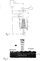
- the laser sintering apparatus comprises a build container 1 open at the top with a support 2 carrying the object 3 to be built.
- the support 2 is movable in the build container 1 in a vertical direction and is adjusted in such a way that the layer of the object which is to be solidified defines a working plane 4.
- a layer generating device 5 for generating a layer of pulverulent build material on the support or on a previously applied layer is provided.
- the laser sintering apparatus further comprises a laser 6 emitting a laser beam 7 which is deflected by a deflection unit 8 and passes through an optical unit 10 which focuses the laser beam onto the working plane 4.
- a control unit 9 controls the deflection unit 8 and the optical unit 10 in such a way that the laser beam 7 can be focussed to any position in the working plane.
- a powder reservoir and feeding device 11 is provided which is, in the example shown, arranged above the build container and which contains the pulverulent build material and feeds it to the layer generating device 5.
- the pulverulent build material is a stainless steel powder.
- the powder is produced in a known manner. Preferably it is produced by means of an atomisation process, for example gas atomisation, wherein the molten material undergoes atomisation using gases. However, other processes may also be used, for example water atomisation.
- each powder particle has the same or at least a similar chemical composition.
- the components can be pre-alloyed.
- the powder particles have spherical or approximately spherical shape with an aspect ratio up to 1:2.
- the grain size distribution of the powder particles according to the invention is between 0,1 ⁇ m and 125 ⁇ m, the median size expressed as d50 value is between 20 ⁇ m and 100 ⁇ m, preferably between 30 ⁇ m and 50 ⁇ m.
- the metal powder according to the invention comprises iron and the following components given in weight percent (wt.-%): carbon: 0.07 max. wt-%, chromium: 14.00 - 15.50 wt.-%, nickel: 3.5 - 5.0 wt.-%, and copper 3.0 - 4.5 wt.-%
- the powder comprises in addition 1.00 max. wt.-% of manganese and/or 0.03 max. wt.-% of phosphorus and/or 0.015 max. wt.-% of sulfur and/or 1.0 max. wt.-% of silicon and/or niobium between 0.15 and 0.45 wt.-% and/or 0.5 max. wt.-% of molybdenum and/or 0.10 max. wt.-% of nitrogen.
- the nitrogen has significant influence on metallurgical phases and can change the metallurgical phase from martensitic to austenitic or semi-austenitic.
- the balance of the composition is iron.
- the powder has a ferrite content of less than 5 wt.-%.
- the powder is a purely metal powder without non-metallic additives such as fluxing agents etc.
- the powder according to the invention comprises the following components in weight percent (wt.-%) : carbon: 0.02 (max. 0.04) wt.-% phosphorus: 0.01 (max. 0.02) wt.-% silicon: 0.4 (max. 0.6) wt.-% nickel: 4.2 ⁇ 0.2 wt.-% copper: 3.6 ⁇ 0.2 wt.-% manganese: 0.1 (max. 0.2) wt.-% sulfur: 0.01 (max. 0.01) wt.-% chromium: 14.3 ⁇ 0.2 wt.-% molybdenum: 0.0 (max. 0.2) wt.-% niobium: 0.30 ⁇ 0.05 wt.-% Iron: balance Nitrogen: 0.04 (max. 0.08) wt.-%
- the median particle size (d50) of the preferred example is between 30 ⁇ m and 40 ⁇ m.
- the method according to the invention is explained with reference to Figs. 1 and 2 using laser sintering as an additive process for manufacturing the object 3.
- the data of the 3D-CAD model of the object 3 to be built are converted in a known manner and transferred to the computer of the laser sintering apparatus for controlling the laser sintering apparatus during the sintering process.
- the powder according to the invention is dispensed onto the support or a previous layer and thereafter sintered or melted in each layer at locations corresponding to the cross-section of the object 3.
- the focused laser beam spot size at the powder melting level is between 20 ⁇ m and 500 ⁇ m, preferably approximately 120 ⁇ m.
- the laser scanning velocity is between 50 mm/s and 10000 mm/s, preferably approximately 1000 mm/s and the distance between adjacent scan lines is between 0.02 mm and 0.5 mm, preferably approximately 0.1 mm.
- the thickness of the powder layer is between 10 ⁇ m and 200 ⁇ m preferably approximately 20 ⁇ m.
- An inert gas flow may be used to avoid chemical reaction of the powder with surrounding material or air.
- the laser beam scans the surface of the metal powder layer.
- the high intensity laser radiation is absorbed by the powder particles and creates extremly rapid heating in the powder to melt the powder.
- heat is conducted away from the previously melted area via the solid metal and/or metal powder under and/or around it, leading to rapid cooling and resolidification.
- Active cooling can be carried out for example by means of cooling the support platform or by means of a flow of cooled gas.
- the laser sintered object is a stainless steel object having less than 20% of the austenitic phase.
- the object 3 is post-treated.
- Heat treatment can be carried out at a variety of temperatures to develop specific properties.
- the eight standard heat treatments H900, H925, H1025, H1075, H1100, H1150, H1150+1150, H1150-M can be carried out.
- solution annealing (SA) can be carried out to obtain desired properties. It has been observed that high cooling rates to a relatively low temperature during laser processing are essential in order to obtain a complete martensitic transformation and to avoid excess amount of remaining austenite phase in the resolidified metal. This is important for the subsequent post-treatments like H900, H925, H1025, etc. if the treatments are to be done without solution annealing and quenching. If the cooling rate is not sufficient and the martensitic transformation is only partial then additional solution annealing and subsequent quench is needed to obtain a fully martensitic phase structure which is more favourable for post-hardening treatments like H900, H925.
- the method according to the invention has the additional advantage that by carrying out the laser processing with rapid cooling and resolidification, additional steps of post-treatment such as solution annealing and quenching can be omitted. Hence, the process chain becomes shorter.
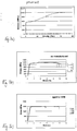
- Fig. 3a) to 3c show a typical tensile testing behaviour of a laser sintered specimen.
- the tensile testing behaviour has been tested with a 3.56mm thick flat test specimen according to MPIF 10 standard.
- Fig. 3a shows the result for a specimen produced using known stainless steel powder 17-4 PH.
- Fig. 3b shows a typical tensile testing behaviour of specimens produced using the metal powder according to the above described preferred embodiment of the invention.
- C1, C2 and C3 are measurement results from three specimens manufactured under the same conditions, i.e. identical process parameters and geometries.
- Fig. 3c shows a typical tensile testing behaviour of specimens which are aged according to H900 condition after laser sintering.
- D1, D2 and D3 are measurement results of three specimens with the same process parameters and the same H900 heat treatment condition.
- the object produced using the metal powder according to the invention has considerably higher strength than the object which is produced using known stainless steel powder. Strength can be enhanced further by using heat treatment.
- Fig. 4 shows the yield and ultimate tensile strength of objects produced by laser sintering using the metal powder according to the above preferred embodiment wherein the object underwent various heat treatment conditions, respectively. As can be seen, the precipitation hardening is applicable.
- HV1 is the hardness in Vickers units using 1 kg load for testing; HRC is the hardness in Rockwell C scale.
- the objects produced with laser sintering and using the metal powder according to the invention are stronger, stiffer and harder than that produced using the powder according to the prior art.
- a heat treatment comprising ageing at 482°C for one hour and air cooling provides superior mechanical properties due to precipitation hardening. Solution annealing and quenching is not required before the ageing treatment.
- the metal powder according to the invention is not limited to the examples described above.
- the metal powder can be a blend of different component powders each having the above composition but which have different particle size distributions. Such blends can be beneficial for fine tuning the grain size distribution of the resulting blended powder.
- the invention is not limited in the application to the laser sintering technique. Moreover, electron beam sintering or melting can also be used. The invention is not even limited to additive layer-wise production methods but includes other additive and free-form production methods of three-dimensional objects such as, for example, the 3D laser-cladding method.
Landscapes
- Chemical & Material Sciences (AREA)
- Engineering & Computer Science (AREA)
- Materials Engineering (AREA)
- Manufacturing & Machinery (AREA)
- Mechanical Engineering (AREA)
- Metallurgy (AREA)
- Organic Chemistry (AREA)
- Physics & Mathematics (AREA)
- Plasma & Fusion (AREA)
- Optics & Photonics (AREA)
- Powder Metallurgy (AREA)
Description
- The invention relates to a metal powder for use in an additive method for the production of three-dimensional objects and to a method using such a powder.
- Direct Metal Laser Sintering (DMLS) is a laser-based rapid prototyping and tooling process by means of which net shape parts are fabricated in a single process. Complex parts can be produced directly from 3D-CAD models by layer-wise solidification of metal powder layers in portions of the layer corresponding to the cross-section of the three-dimensional part in the respective layer. This process is described in detail for example in Juha Kotila et al., Steel-based Metal Powder Blend for Direct Metal Laser Sintering Process, Advances in Powder Metallurgy & Particular Materials - 1999, Vol.2 Part 5, p. 87-93 and in T. Syvänen et al., New Innovations in Direct Metal Laser Sintering Process - A Step Forward in Rapid Prototyping and Manufacturing, Laser Materials Processing, Vol. 87, 1999, p. 68 to 76.
- There is a high demand for processing metal materials by additive manufacturing processes such as Direct Metal Laser Sintering, so that rapid manufacturing can be applied to applications where a specific material having well-known properties is required. One important class of materials is stainless steel which is widely used in many products. Many different kinds of stainless steel exist and are commercially available for conventional manufacturing methods, such as casting, forging, machining etc. as referenced in international standards, reference books, manufacturers' catalogues etc.
- One example of a well-known conventional stainless steel is 17-4 PH (US designation) corresponding to 1.4542 European designation. An important characteristic of this material in conventional use is that it can be post-hardened by precipitation hardening ("PH") to significantly increase the hardness. This material in powdered form can be processed by laser sintering to produce metal parts with good quality. Depending on how the parameters which are used in this process are selected, different metallurgical phases can be produced. It has been found that the conventional precipitation hardening process does not work for parts produced by direct metal laser sintering using powder material corresponding to stainless steel 17-4PH and typical processing parameters known from the prior art.
- 316 L/1.4404 stainless steel has also been used for laser sintering or laser melting.
- In
WO 02/092264 A JP10102105 A US2004/182202 A1 . - It is the object of the invention to provide a metal powder which can be processed by laser sintering or similar additive manufacturing methods using a heat source and whereby the object produced has similar properties compared to that of a stainless steel object produced using a conventional manufacturing method. In particular, the object should be able to undergo the precipitation hardening process to fulfil the requirements of users. Furthermore, a method for producing a three-dimensional object shall be provided.
- The object is solved by a metal powder according to claim 1 and by a method according to claim 7. Further developments are given in the dependent claims.
- The metal powder according to the invention has the advantage that the object produced can be post-hardened, in particular by means of precipitation hardening, to significantly increase the hardness. Furthermore, the mechanical properties of the three-dimensional object produced by an additive manufacturing method are similar to those achieved using conventional 17-4 PH stainless steel and a conventional manufacturing method. This opens a wide range of applications for laser sintering and other additive processes.
- Further advantages of the invention will become apparent from the description of embodiments in conjunction with the accompanying drawings, wherein:
- Fig. 1
- is a schematic representation of a laser sintering apparatus,
- Fig. 2
- is a schematic presentation of laser scanning in the DLMS-process,
- Fig. 3a) - 3c)
- graphs showing the result of typical tensile testing behaviour of parts produced using the metal powder according to the invention, and
- Fig. 4
- shows yield and ultimate tensile strength results of parts produced using the metal powder according to the invention with different heat treatment cycles.
- The invention will now be described with reference to the direct metal laser sintering process as an example for an additive manufacturing method. As shown in
Fig. 1 the laser sintering apparatus comprises a build container 1 open at the top with asupport 2 carrying theobject 3 to be built. Thesupport 2 is movable in the build container 1 in a vertical direction and is adjusted in such a way that the layer of the object which is to be solidified defines a working plane 4. A layer generating device 5 for generating a layer of pulverulent build material on the support or on a previously applied layer is provided. The laser sintering apparatus further comprises alaser 6 emitting a laser beam 7 which is deflected by adeflection unit 8 and passes through anoptical unit 10 which focuses the laser beam onto the working plane 4. Acontrol unit 9 controls thedeflection unit 8 and theoptical unit 10 in such a way that the laser beam 7 can be focussed to any position in the working plane. A powder reservoir andfeeding device 11 is provided which is, in the example shown, arranged above the build container and which contains the pulverulent build material and feeds it to the layer generating device 5. - According to the invention, the pulverulent build material is a stainless steel powder. The powder is produced in a known manner. Preferably it is produced by means of an atomisation process, for example gas atomisation, wherein the molten material undergoes atomisation using gases. However, other processes may also be used, for example water atomisation. As a result of the production process, each powder particle has the same or at least a similar chemical composition. The components can be pre-alloyed. In addition, the powder particles have spherical or approximately spherical shape with an aspect ratio up to 1:2.
- The grain size distribution of the powder particles according to the invention is between 0,1µm and 125µm, the median size expressed as d50 value is between 20 µm and 100 µm, preferably between 30 µm and 50 µm.
- The metal powder according to the invention, comprises iron and the following components given in weight percent (wt.-%):
carbon: 0.07 max. wt-%, chromium: 14.00 - 15.50 wt.-%, nickel: 3.5 - 5.0 wt.-%, and copper 3.0 - 4.5 wt.-% - The powder comprises in addition 1.00 max. wt.-% of manganese and/or 0.03 max. wt.-% of phosphorus and/or 0.015 max. wt.-% of sulfur and/or 1.0 max. wt.-% of silicon and/or niobium between 0.15 and 0.45 wt.-% and/or 0.5 max. wt.-% of molybdenum and/or 0.10 max. wt.-% of nitrogen. The nitrogen has significant influence on metallurgical phases and can change the metallurgical phase from martensitic to austenitic or semi-austenitic. The balance of the composition is iron.
- The powder has a ferrite content of less than 5 wt.-%.
- The powder is a purely metal powder without non-metallic additives such as fluxing agents etc.
- In a preferred embodiment, the powder according to the invention comprises the following components in weight percent (wt.-%) :
carbon: 0.02 (max. 0.04) wt.-% phosphorus: 0.01 (max. 0.02) wt.-% silicon: 0.4 (max. 0.6) wt.-% nickel: 4.2 ±0.2 wt.-% copper: 3.6 ±0.2 wt.-% manganese: 0.1 (max. 0.2) wt.-% sulfur: 0.01 (max. 0.01) wt.-% chromium: 14.3 ±0.2 wt.-% molybdenum: 0.0 (max. 0.2) wt.-% niobium: 0.30 ±0.05 wt.-% Iron: balance Nitrogen: 0.04 (max. 0.08) wt.-% - The median particle size (d50) of the preferred example is between 30 µm and 40 µm.
- The method according to the invention is explained with reference to
Figs. 1 and 2 using laser sintering as an additive process for manufacturing theobject 3. The data of the 3D-CAD model of theobject 3 to be built are converted in a known manner and transferred to the computer of the laser sintering apparatus for controlling the laser sintering apparatus during the sintering process. The powder according to the invention is dispensed onto the support or a previous layer and thereafter sintered or melted in each layer at locations corresponding to the cross-section of theobject 3. - A laser with a power between 20 W and 1 kW, preferably approximately 200 W, is used. The focused laser beam spot size at the powder melting level is between 20 µm and 500 µm, preferably approximately 120 µm. The laser scanning velocity is between 50 mm/s and 10000 mm/s, preferably approximately 1000 mm/s and the distance between adjacent scan lines is between 0.02 mm and 0.5 mm, preferably approximately 0.1 mm. The thickness of the powder layer is between 10 µm and 200 µm preferably approximately 20 µm. These parameters are selected depending on the ranges depending on the object to be built.
- An inert gas flow may be used to avoid chemical reaction of the powder with surrounding material or air. During the sintering process the laser beam scans the surface of the metal powder layer. The high intensity laser radiation is absorbed by the powder particles and creates extremly rapid heating in the powder to melt the powder. As the scanned laser beam moves on, heat is conducted away from the previously melted area via the solid metal and/or metal powder under and/or around it, leading to rapid cooling and resolidification. By keeping the temperature of the process chamber relatively low, for example by not applying additional heating in addition to the laser beam, a high cooling rate and lower temperature after resolidification is obtained. It is also possible to apply active cooling to remove heat from the solidified material during the laser processing to obtain an even higher cooling rate and/or lower temperature after resolidification. Active cooling can be carried out for example by means of cooling the support platform or by means of a flow of cooled gas.
- When the laser sintering process is finished, the unsintered powder is removed and the laser sintered object is removed from the build container 1. The laser sintered object is a stainless steel object having less than 20% of the austenitic phase.
- For specific applications the
object 3 is post-treated. Heat treatment can be carried out at a variety of temperatures to develop specific properties. For example, the eight standard heat treatments H900, H925, H1025, H1075, H1100, H1150, H1150+1150, H1150-M can be carried out. Also, solution annealing (SA) can be carried out to obtain desired properties. It has been observed that high cooling rates to a relatively low temperature during laser processing are essential in order to obtain a complete martensitic transformation and to avoid excess amount of remaining austenite phase in the resolidified metal. This is important for the subsequent post-treatments like H900, H925, H1025, etc. if the treatments are to be done without solution annealing and quenching. If the cooling rate is not sufficient and the martensitic transformation is only partial then additional solution annealing and subsequent quench is needed to obtain a fully martensitic phase structure which is more favourable for post-hardening treatments like H900, H925. - The method according to the invention has the additional advantage that by carrying out the laser processing with rapid cooling and resolidification, additional steps of post-treatment such as solution annealing and quenching can be omitted. Hence, the process chain becomes shorter.
-
Fig. 3a) to 3c ) show a typical tensile testing behaviour of a laser sintered specimen. The tensile testing behaviour has been tested with a 3.56mm thick flat test specimen according to MPIF 10 standard. -
Fig. 3a ) shows the result for a specimen produced using known stainless steel powder 17-4 PH. -
Fig. 3b ) shows a typical tensile testing behaviour of specimens produced using the metal powder according to the above described preferred embodiment of the invention. C1, C2 and C3 are measurement results from three specimens manufactured under the same conditions, i.e. identical process parameters and geometries. -
Fig. 3c ) shows a typical tensile testing behaviour of specimens which are aged according to H900 condition after laser sintering. D1, D2 and D3 are measurement results of three specimens with the same process parameters and the same H900 heat treatment condition. As can be seen from the comparison with the prior art, the object produced using the metal powder according to the invention has considerably higher strength than the object which is produced using known stainless steel powder. Strength can be enhanced further by using heat treatment. -
Fig. 4 shows the yield and ultimate tensile strength of objects produced by laser sintering using the metal powder according to the above preferred embodiment wherein the object underwent various heat treatment conditions, respectively. As can be seen, the precipitation hardening is applicable. - In the following, the mechanical properties of an object produced using the known stainless steel 17-4 PH powder are compared to an identical object produced using the metal powder according to the invention and which was H900 heat treated after finishing the laser sintering process:
Property object produced using known stainless steel powder 17-4 PH object produced using metal powder according to invention H900 heat treated Ultimate tensile strength, MPa 1050 ±50 MPa 1486 ±50 MPa (152 ±7 ksi) (216 ±7 ksi) Yield strength (Rp 0.2 %), MPa 540 ±50 MPa 1382 ±50 MPa (78 ±7 ksi) (200 ±7 ksi) Young's Modulus (GPa) 180 ±20 GPa 190 ±20 GPa (26 ±3 msi) (28 ±3 msi) Remaining elongation 30 ±5 % 5 ±2 % Surface hardness - as laser-sintered 230 ±20 HV1 30 ±5 HRC - H900 aged xxxxxx 43 ±3 HRC - HV1 is the hardness in Vickers units using 1 kg load for testing; HRC is the hardness in Rockwell C scale.
- The objects produced with laser sintering and using the metal powder according to the invention, are stronger, stiffer and harder than that produced using the powder according to the prior art. Preferably a heat treatment comprising ageing at 482°C for one hour and air cooling provides superior mechanical properties due to precipitation hardening. Solution annealing and quenching is not required before the ageing treatment.
- All numerical values given above are to be understood as including the usual measuring tolerances.
- The metal powder according to the invention is not limited to the examples described above. For example the metal powder can be a blend of different component powders each having the above composition but which have different particle size distributions. Such blends can be beneficial for fine tuning the grain size distribution of the resulting blended powder.
- The invention is not limited in the application to the laser sintering technique. Moreover, electron beam sintering or melting can also be used. The invention is not even limited to additive layer-wise production methods but includes other additive and free-form production methods of three-dimensional objects such as, for example, the 3D laser-cladding method.
Claims (14)
- Metal powder for use in an additive production method of three-dimensional objects wherein the powder is solidified by means of a laser or electron beam or another heat source,wherein the powder is a stainless steel powder,wherein the powder comprises iron and the following components by weight percent (wt.-%)
carbon: 0.07 max. wt-%, chromium: 14.00 - 15.50 wt.-%, nickel: 3.5 - 5.0 wt.-%, manganese: 1.00 max. wt.-%, phosphorus: 0.03 max. wt.-%, sulfur: 0.015 max. wt.-%, silicon: 1.00 max. wt.-%, molybdenum: 0.5 max. wt.-%, nitrogen: 0.10 max. wt.-%, copper: 3.0 - 4.5 wt.-%, optionally niobium: 0.15 - 0.45 wt.-%, and iron: balance, wherein the powder particles have a median particle size d50 between 20µm and 100µm andwherein the content of ferrite is less than 5 wt.-%, andwherein the powder particles have an approximately spherical shape with an aspect ratio up to 1:2. - The metal powder according to claim 1, wherein the powder is produced by atomisation.
- The metal powder according to one of claims 1 to 2, wherein the component elements are contained in each powder particle in a pre-alloyed manner.
- The metal powder according to one of claims 1 to 2, wherein the powder is a blend of different component powders having different grain size distributions and/or chemical compositions.
- The metal powder according to one of claims 1 to 4, characterized in that the powder is in the martensitic state.
- The metal powder according to one of claims 1 to 5, comprising
carbon: 0.02 to 0.04 wt.-% phosphorus: 0.01 to 0.02 wt.-% silicon: 0.4 to 0.6 wt.-% nickel: 4.2 ±0.2 wt.-% copper: 3.6 ±0.2 wt.-% manganese: 0.1 to 0.2 wt.-% sulfur: 0.01 to 0.01 wt.-% chromium: 14.3 ±0.2 wt.-% molybdenum: 0.0 to 0.2 wt.-% niobium: 0.3 ±0.05 wt.-% Iron: balance Nitrogen: 0.04 to 0.08 wt.-% - Method for the production of three-dimensional objects from a powder, wherein the powder is applied in an additive manner and is melted by means of a laser or electron beam, and wherein the melted powder undergoes rapid cooling and resolidification, characterized in that the powder used is a powder according to one of claims 1 to 6.
- The method according to claim 7, wherein the powder is applied in a layer-wise manner and selectively solidified in each layer at locations corresponding to the cross-section of the object.
- The method according to claim 7 or 8, wherein a laser beam is used with a laser power between 20 W and 1 kW, preferably approximately 200 W.
- The method according to one of claims 7 to 9, wherein the focused laser beam spot size at the powder melting level is between 20 µm and 500 µm, preferably approximately 120 µm.
- The method according to one of claims 7 to 10, wherein the laser scanning velocity is between 50 mm/s and 10000 mm/s, preferably approximately 1000 mm/s.
- The method according to one of claims 8 to 11, wherein the distance between adjacent scan lines is between 0.02 and 0.5 mm, preferably approximately 0.1 mm.
- The method according to one of claims 8 to 12, wherein the thickness of the powder layer is between 10 µm and 200 µm, preferably approximately 20 µm.
- The method according to one of claims 7 to 13, wherein the object is precipitation hardened after the layer-wise formation.
Priority Applications (2)
| Application Number | Priority Date | Filing Date | Title |
|---|---|---|---|
| EP07009626.8A EP1992709B1 (en) | 2007-05-14 | 2007-05-14 | Metal powder for use in additive manufacturing method for the production of three-dimensional objects and method using such metal powder |
| US12/152,452 US20090047165A1 (en) | 2007-05-14 | 2008-05-13 | Metal powder for use in an additive method for the production of three-dimensional objects and method using such metal powder |
Applications Claiming Priority (1)
| Application Number | Priority Date | Filing Date | Title |
|---|---|---|---|
| EP07009626.8A EP1992709B1 (en) | 2007-05-14 | 2007-05-14 | Metal powder for use in additive manufacturing method for the production of three-dimensional objects and method using such metal powder |
Publications (2)
| Publication Number | Publication Date |
|---|---|
| EP1992709A1 EP1992709A1 (en) | 2008-11-19 |
| EP1992709B1 true EP1992709B1 (en) | 2021-09-15 |
Family
ID=38535603
Family Applications (1)
| Application Number | Title | Priority Date | Filing Date |
|---|---|---|---|
| EP07009626.8A Active EP1992709B1 (en) | 2007-05-14 | 2007-05-14 | Metal powder for use in additive manufacturing method for the production of three-dimensional objects and method using such metal powder |
Country Status (2)
| Country | Link |
|---|---|
| US (1) | US20090047165A1 (en) |
| EP (1) | EP1992709B1 (en) |
Families Citing this family (53)
| Publication number | Priority date | Publication date | Assignee | Title |
|---|---|---|---|---|
| ITMO20080260A1 (en) * | 2008-10-03 | 2010-04-04 | Eurocoating S P A | PROCEDURE TO INCREASE THE SURFACE HARDNESS OF STEEL MANUFACTURES |
| US9330406B2 (en) | 2009-05-19 | 2016-05-03 | Cobra Golf Incorporated | Method and system for sales of golf equipment |
| US20180253774A1 (en) * | 2009-05-19 | 2018-09-06 | Cobra Golf Incorporated | Method and system for making golf club components |
| DE102010029078A1 (en) * | 2010-05-18 | 2011-11-24 | Matthias Fockele | Producing an article by layer-wise structures made of powdered metallic or ceramic material, comprises individually preparing material powder layers subsequent to each other on a support, and location-selectively solidifying each layer |
| DE112011101779T5 (en) * | 2010-05-25 | 2013-03-14 | Panasonic Corporation | Metal powder for selective laser sintering, process for producing a three-dimensional molded article using the same, and three-dimensional molded article obtained therefrom |
| ITVR20100232A1 (en) * | 2010-12-09 | 2012-06-10 | Eurocoating S P A | METHOD OF THERMAL TREATMENT OF PIECES IN STAINLESS STEEL HARDENING FOR PRECIPITATION MADE WITH QUICK AND SIMILAR PROTOTYPING TECHNIQUES |
| CN102166651A (en) * | 2011-03-29 | 2011-08-31 | 黑龙江科技学院 | Method for manufacturing porous metal parts by laser scanning |
| CH705750A1 (en) * | 2011-10-31 | 2013-05-15 | Alstom Technology Ltd | A process for the production of components or portions, which consist of a high-temperature superalloy. |
| CA2872397C (en) * | 2012-05-03 | 2021-10-19 | DePuy Synthes Products, LLC | Surgical guides from scanned implant data |
| US9411939B2 (en) | 2012-09-12 | 2016-08-09 | DePuy Synthes Products, Inc. | Method for producing patient-specific plate |
| US20140170012A1 (en) * | 2012-12-18 | 2014-06-19 | United Technologies Corporation | Additive manufacturing using partially sintered layers |
| EP2969485B1 (en) | 2013-03-15 | 2019-06-05 | 3D Systems, Inc. | Chute for laser sintering systems |
| WO2015057304A1 (en) * | 2013-10-18 | 2015-04-23 | Burd Steven W | Panel with cooling holes and methods for fabricating same |
| US10011894B2 (en) | 2014-03-14 | 2018-07-03 | Sanyo Special Steel Co., Ltd. | Precipitation-hardening stainless steel powder and sintered compact thereof |
| AU2015258806B2 (en) * | 2014-05-16 | 2019-05-16 | The Nanosteel Company, Inc. | Layered construction of metallic materials |
| PT2952275T (en) | 2014-06-04 | 2017-05-03 | Carl Aug Picard Gmbh | Screw feed element and method for the additive manufacture of screw feed elements |
| GB2546016B (en) | 2014-06-20 | 2018-11-28 | Velo3D Inc | Apparatuses, systems and methods for three-dimensional printing |
| JP2016053198A (en) * | 2014-09-04 | 2016-04-14 | 株式会社コイワイ | Metal molded product and metal powder for metal molded product |
| CN104801703B (en) * | 2015-03-26 | 2016-08-24 | 成都新柯力化工科技有限公司 | A kind of flexible metal powder for 3 D-printing and its preparation method and application method |
| DE102015205787A1 (en) * | 2015-03-31 | 2016-10-06 | Siemens Aktiengesellschaft | Method for producing a component from MAX phases |
| JP2018535121A (en) | 2015-11-06 | 2018-11-29 | ヴェロ・スリー・ディー・インコーポレイテッド | Proficient 3D printing |
| US10207454B2 (en) | 2015-12-10 | 2019-02-19 | Velo3D, Inc. | Systems for three-dimensional printing |
| US20170239891A1 (en) | 2016-02-18 | 2017-08-24 | Velo3D, Inc. | Accurate three-dimensional printing |
| US11691343B2 (en) | 2016-06-29 | 2023-07-04 | Velo3D, Inc. | Three-dimensional printing and three-dimensional printers |
| WO2018005439A1 (en) | 2016-06-29 | 2018-01-04 | Velo3D, Inc. | Three-dimensional printing and three-dimensional printers |
| US20180095450A1 (en) | 2016-09-30 | 2018-04-05 | Velo3D, Inc. | Three-dimensional objects and their formation |
| BR112019008959B1 (en) | 2016-11-01 | 2023-01-10 | The Nanosteel Company, Inc | 3D PRINTING HARD IRON METAL ALLOYS FOR POWDER BED FUSION |
| US10953465B2 (en) | 2016-11-01 | 2021-03-23 | The Nanosteel Company, Inc. | 3D printable hard ferrous metallic alloys for powder bed fusion |
| US10661341B2 (en) | 2016-11-07 | 2020-05-26 | Velo3D, Inc. | Gas flow in three-dimensional printing |
| US20180186080A1 (en) | 2017-01-05 | 2018-07-05 | Velo3D, Inc. | Optics in three-dimensional printing |
| WO2018160807A1 (en) | 2017-03-02 | 2018-09-07 | Velo3D, Inc. | Three-dimensional printing of three dimensional objects |
| US10449696B2 (en) | 2017-03-28 | 2019-10-22 | Velo3D, Inc. | Material manipulation in three-dimensional printing |
| AT16217U1 (en) | 2017-10-05 | 2019-03-15 | Plansee Se | Additive manufactured component |
| US10272525B1 (en) | 2017-12-27 | 2019-04-30 | Velo3D, Inc. | Three-dimensional printing systems and methods of their use |
| CN111356546A (en) | 2018-01-02 | 2020-06-30 | 惠普发展公司,有限责任合伙企业 | Powder bed material |
| JP6985940B2 (en) * | 2018-01-09 | 2021-12-22 | 山陽特殊製鋼株式会社 | Stainless steel powder for modeling |
| JP7213320B2 (en) * | 2018-01-09 | 2023-01-26 | 山陽特殊製鋼株式会社 | stainless steel powder for molding |
| US10144176B1 (en) | 2018-01-15 | 2018-12-04 | Velo3D, Inc. | Three-dimensional printing systems and methods of their use |
| CN108339983B (en) * | 2018-04-02 | 2020-05-12 | 广州恒尚科技有限公司 | Selective laser melting forming method for 304 stainless steel or 304L stainless steel |
| CN109536857A (en) * | 2018-12-04 | 2019-03-29 | 深圳大学 | A kind of Fe base noncrystal alloy part and preparation method thereof |
| WO2020185641A1 (en) * | 2019-03-14 | 2020-09-17 | Hoeganaes Corporation | Metallurgical compositions for press-and sinter and additive manufacturing |
| CN109913766B (en) * | 2019-04-09 | 2020-12-25 | 东北大学 | 50Cr6Ni2Y alloy steel powder for laser additive manufacturing and preparation method thereof |
| CA3148849A1 (en) | 2019-07-26 | 2021-02-04 | Velo3D, Inc. | Quality assurance in formation of three-dimensional objects |
| CN110629131A (en) * | 2019-09-26 | 2019-12-31 | 上海镭镆科技有限公司 | A kind of 3D printing stainless steel material and preparation method and application |
| JP6864056B1 (en) * | 2019-10-23 | 2021-04-21 | 株式会社ソディック | Laminated modeling equipment |
| GB201915462D0 (en) * | 2019-10-24 | 2019-12-11 | Speciality Steel Uk Ltd | Steel alloy |
| WO2021084025A1 (en) | 2019-10-31 | 2021-05-06 | Deutsche Edelstahlwerke Specialty Steel Gmbh & Co. Kg | Corrosion-resistant and precipitation-hardening steel, method for producing a steel component, and steel component |
| EP3900856A1 (en) | 2020-04-24 | 2021-10-27 | Technische Universität Graz | Additive manufacturing powders for use in additive manufacturing processes resulting in improved stability of steel melt-track |
| CN112030068A (en) * | 2020-08-06 | 2020-12-04 | 陕西陕北矿业有限责任公司 | Laser cladding iron-based alloy powder and preparation method and application thereof |
| JP7324803B2 (en) * | 2020-09-11 | 2023-08-10 | クエステック イノベーションズ リミテッド ライアビリティ カンパニー | Stainless Steel Powder for Additive Manufacturing |
| EP4174206A1 (en) | 2021-11-01 | 2023-05-03 | QuesTek Innovations LLC | Stainless steel powders for additive manufacturing |
| CN114570941B (en) * | 2022-02-15 | 2023-08-25 | 西安建筑科技大学 | Process for preparing 17-4PH martensitic precipitation stainless steel by electron beam |
| CN115502404B (en) * | 2022-11-09 | 2024-01-19 | 西安理工大学 | Method for preparing heterogeneous layered metal materials using powder metallurgy |
Family Cites Families (18)
| Publication number | Priority date | Publication date | Assignee | Title |
|---|---|---|---|---|
| US4430115A (en) * | 1980-05-27 | 1984-02-07 | Marko Materials, Inc. | Boron stainless steel powder and rapid solidification method |
| JPS6230858A (en) * | 1985-07-31 | 1987-02-09 | Daido Steel Co Ltd | Stainless shot |
| JPH10102105A (en) * | 1996-09-25 | 1998-04-21 | Taiheiyo Kinzoku Kk | Production method of metal fine powder |
| DE60014331T2 (en) * | 1999-03-08 | 2006-02-09 | CRS Holdings, Inc., Wilmington | DEPENDABLE AND STAINLESS STEEL WITH IMPROVED PROCESSABILITY FOR SPECIAL APPLICATION purposes |
| DE10039144C1 (en) * | 2000-08-07 | 2001-11-22 | Fraunhofer Ges Forschung | Production of precise components comprises laser sintering a powder mixture made from a mixture of iron powder and further powder alloying elements |
| DE10104732C1 (en) * | 2001-02-02 | 2002-06-27 | Fraunhofer Ges Forschung | Device for selective laser melting of metallic materials comprises a heating plate arranged on a platform with side walls, and an insulating layer thermally insulated from the platform |
| SE520974C2 (en) * | 2001-05-11 | 2003-09-16 | Iuc Karlskoga Ab | Procedure for free-form metal powder and metal powder mixture |
| US6461452B1 (en) * | 2001-05-16 | 2002-10-08 | Crs Holdings, Inc. | Free-machining, martensitic, precipitation-hardenable stainless steel |
| US6814926B2 (en) * | 2003-03-19 | 2004-11-09 | 3D Systems Inc. | Metal powder composition for laser sintering |
| DE10342882A1 (en) * | 2003-09-15 | 2005-05-19 | Trumpf Werkzeugmaschinen Gmbh + Co. Kg | Apparatus and method for producing a three-dimensional shaped body |
| DE102006053121B3 (en) * | 2006-11-10 | 2007-12-27 | Eos Gmbh Electro Optical Systems | Coating device for applying powdered layers to a device for producing a three-dimensional object comprises longitudinal walls joined together, a unit for fluidizing powdered material and a controlling and/or regulating unit |
| DE102006055073A1 (en) * | 2006-11-22 | 2008-05-29 | Eos Gmbh Electro Optical Systems | Apparatus and method for layering a three-dimensional object |
| DE102006055078A1 (en) * | 2006-11-22 | 2008-06-05 | Eos Gmbh Electro Optical Systems | Apparatus for layering a three-dimensional object |
| US8017070B2 (en) * | 2007-05-17 | 2011-09-13 | The Boeing Company | Direct to metal sintering of 17-4PH steel |
| JP5584019B2 (en) * | 2010-06-09 | 2014-09-03 | パナソニック株式会社 | Manufacturing method of three-dimensional shaped object and three-dimensional shaped object obtained therefrom |
| WO2012160811A1 (en) * | 2011-05-23 | 2012-11-29 | パナソニック株式会社 | Method for producing three-dimensional shape structure |
| DE102012206122A1 (en) * | 2012-04-13 | 2013-10-17 | MTU Aero Engines AG | Multiple coil arrangement for a device for the generative production of components and corresponding manufacturing method |
| DE102015205314A1 (en) * | 2015-03-24 | 2016-09-29 | Siemens Aktiengesellschaft | Plant for an additive manufacturing process with a heater for the powder chamber |
-
2007
- 2007-05-14 EP EP07009626.8A patent/EP1992709B1/en active Active
-
2008
- 2008-05-13 US US12/152,452 patent/US20090047165A1/en not_active Abandoned
Also Published As
| Publication number | Publication date |
|---|---|
| US20090047165A1 (en) | 2009-02-19 |
| EP1992709A1 (en) | 2008-11-19 |
Similar Documents
| Publication | Publication Date | Title |
|---|---|---|
| EP1992709A1 (en) | Metal powder for use in additive method for the production of three-dimensional objects and method using such metal powder | |
| CA2823267C (en) | Iron based powders for powder injection molding | |
| Simchi et al. | On the development of direct metal laser sintering for rapid tooling | |
| KR101711496B1 (en) | High strength low alloyed sintered steel | |
| JP6688287B2 (en) | Pre-alloyed iron-based powder, iron-based powder mixture containing pre-alloyed iron-based powder, and method of manufacturing press-formed and sintered parts from the iron-based powder mixture | |
| CN111954725A (en) | Additive layer-manufactured hot-work mold, method of making the same, and metal powder for additive-layer-manufactured hot-work mold | |
| US12227825B2 (en) | Stainless steel powders for additive manufacturing | |
| Jamshidinia et al. | Additive manufacturing of steel alloys using laser powder-bed fusion | |
| JP2023511877A (en) | Metal powders for additive manufacturing processes, uses thereof, methods of making parts, and parts thereof | |
| US20240068074A1 (en) | Titanium alloy and methods of manufacture | |
| EP1027467B1 (en) | Method for manufacturing high carbon sintered powder metal steel parts of high density | |
| JP2022176862A (en) | HIGH HARDNESS Co-FREE MARAGING STEEL | |
| US20090142219A1 (en) | Sinter-hardening powder and their sintered compacts | |
| Nobrega et al. | MIM processing and plasma sintering of nickel base superalloys for aerospace and automotive applications | |
| EP4215298A1 (en) | Tool steel powder for additive manufacturing | |
| JP7775993B2 (en) | Fe-based alloy, alloy member, product, and method for manufacturing alloy member | |
| WO2023182416A1 (en) | Maraging steel powder for lamination shaping, maraging steel lamination shaped article, and method for manufacturing same | |
| JP7811506B2 (en) | Iron and steel materials for additive manufacturing and manufacturing method of iron alloys | |
| JP7798238B2 (en) | Fe-based alloy, alloy member, and method for manufacturing alloy member | |
| RU2327547C1 (en) | Method of producing iron base powder (variants) | |
| Grzesiak et al. | Effects of the Selective Laser Melting Process Parameters on the Functional Properties of the Co-Cr Alloy. | |
| EP4197670A1 (en) | Super duplex stainless steel for additive manufacture | |
| EP3689499A1 (en) | Manufacturing of high temperature aluminum components via coating of base powder | |
| RU2327548C1 (en) | Method of producing iron base powder (its variants) | |
| EP4650084A1 (en) | Steel powder for additive manufacturing processes |
Legal Events
| Date | Code | Title | Description |
|---|---|---|---|
| PUAI | Public reference made under article 153(3) epc to a published international application that has entered the european phase |
Free format text: ORIGINAL CODE: 0009012 |
|
| AK | Designated contracting states |
Kind code of ref document: A1 Designated state(s): AT BE BG CH CY CZ DE DK EE ES FI FR GB GR HU IE IS IT LI LT LU LV MC MT NL PL PT RO SE SI SK TR |
|
| AX | Request for extension of the european patent |
Extension state: AL BA HR MK RS |
|
| 17P | Request for examination filed |
Effective date: 20081113 |
|
| 17Q | First examination report despatched |
Effective date: 20090127 |
|
| AKX | Designation fees paid |
Designated state(s): DE FR GB IT |
|
| STAA | Information on the status of an ep patent application or granted ep patent |
Free format text: STATUS: EXAMINATION IS IN PROGRESS |
|
| REG | Reference to a national code |
Ref country code: DE Ref legal event code: R079 Ref document number: 602007061302 Country of ref document: DE Free format text: PREVIOUS MAIN CLASS: C22C0033020000 Ipc: B22F0010280000 |
|
| RIC1 | Information provided on ipc code assigned before grant |
Ipc: B22F 10/28 20210101AFI20210219BHEP Ipc: C22C 33/02 20060101ALI20210219BHEP Ipc: B33Y 70/00 20200101ALI20210219BHEP Ipc: B33Y 10/00 20150101ALI20210219BHEP |
|
| GRAP | Despatch of communication of intention to grant a patent |
Free format text: ORIGINAL CODE: EPIDOSNIGR1 |
|
| STAA | Information on the status of an ep patent application or granted ep patent |
Free format text: STATUS: GRANT OF PATENT IS INTENDED |
|
| INTG | Intention to grant announced |
Effective date: 20210407 |
|
| GRAS | Grant fee paid |
Free format text: ORIGINAL CODE: EPIDOSNIGR3 |
|
| GRAA | (expected) grant |
Free format text: ORIGINAL CODE: 0009210 |
|
| STAA | Information on the status of an ep patent application or granted ep patent |
Free format text: STATUS: THE PATENT HAS BEEN GRANTED |
|
| AK | Designated contracting states |
Kind code of ref document: B1 Designated state(s): DE FR GB IT |
|
| REG | Reference to a national code |
Ref country code: GB Ref legal event code: FG4D |
|
| REG | Reference to a national code |
Ref country code: DE Ref legal event code: R096 Ref document number: 602007061302 Country of ref document: DE |
|
| REG | Reference to a national code |
Ref country code: DE Ref legal event code: R097 Ref document number: 602007061302 Country of ref document: DE |
|
| PLBE | No opposition filed within time limit |
Free format text: ORIGINAL CODE: 0009261 |
|
| STAA | Information on the status of an ep patent application or granted ep patent |
Free format text: STATUS: NO OPPOSITION FILED WITHIN TIME LIMIT |
|
| 26N | No opposition filed |
Effective date: 20220616 |
|
| PGFP | Annual fee paid to national office [announced via postgrant information from national office to epo] |
Ref country code: DE Payment date: 20251021 Year of fee payment: 19 |
|
| PGFP | Annual fee paid to national office [announced via postgrant information from national office to epo] |
Ref country code: GB Payment date: 20251021 Year of fee payment: 19 |
|
| PGFP | Annual fee paid to national office [announced via postgrant information from national office to epo] |
Ref country code: IT Payment date: 20251024 Year of fee payment: 19 |
|
| PGFP | Annual fee paid to national office [announced via postgrant information from national office to epo] |
Ref country code: FR Payment date: 20251029 Year of fee payment: 19 |