EP1992582A1 - Suspension device for elevator - Google Patents
Suspension device for elevator Download PDFInfo
- Publication number
- EP1992582A1 EP1992582A1 EP06728702A EP06728702A EP1992582A1 EP 1992582 A1 EP1992582 A1 EP 1992582A1 EP 06728702 A EP06728702 A EP 06728702A EP 06728702 A EP06728702 A EP 06728702A EP 1992582 A1 EP1992582 A1 EP 1992582A1
- Authority
- EP
- European Patent Office
- Prior art keywords
- displacement
- respect
- raised
- main rope
- urging
- Prior art date
- Legal status (The legal status is an assumption and is not a legal conclusion. Google has not performed a legal analysis and makes no representation as to the accuracy of the status listed.)
- Withdrawn
Links
Images

Classifications
-
- B—PERFORMING OPERATIONS; TRANSPORTING
- B66—HOISTING; LIFTING; HAULING
- B66B—ELEVATORS; ESCALATORS OR MOVING WALKWAYS
- B66B7/00—Other common features of elevators
- B66B7/06—Arrangements of ropes or cables
- B66B7/08—Arrangements of ropes or cables for connection to the cars or cages, e.g. couplings
-
- B—PERFORMING OPERATIONS; TRANSPORTING
- B66—HOISTING; LIFTING; HAULING
- B66B—ELEVATORS; ESCALATORS OR MOVING WALKWAYS
- B66B11/00—Main component parts of lifts in, or associated with, buildings or other structures
- B66B11/02—Cages, i.e. cars
-
- B—PERFORMING OPERATIONS; TRANSPORTING
- B66—HOISTING; LIFTING; HAULING
- B66B—ELEVATORS; ESCALATORS OR MOVING WALKWAYS
- B66B7/00—Other common features of elevators
Definitions
- the present invention relates to a suspension device for an elevator, which serves to suspend a raised/lowered body such as a car.
- Patent Document 1 JP 2005-212941 A
- the present invention has been made to solve the above-mentioned problem, and it is therefore an object of the present invention to provide a suspension device for an elevator, which makes it possible to reduce the dimension of a raised/lowered body in a height direction thereof and prolong the life of a main rope for suspending the raised/lowered body.
- a suspension device for an elevator includes: a main rope for suspending a raised/lowered body; and a cleat device provided on the raised/lowered body and having a turning lever having connected thereto an end of the main rope to be turned with respect to the raised/lowered body through vertical displacement of the raised/lowered body with respect to the end of the main rope, a displacement body that is horizontally displaced with respect to the raised/lowered body through turning of the turning lever, and an urging body for urging the displacement body in such a direction as to act against downward displacement of the raised/lowered body with respect to the end of the main rope.
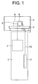
- Fig. 1 is a schematic diagram showing an elevator according to Embodiment 1 of the present invention.
- a car (raised/lowered body) 2 and a counterweight (raised/lowered body) 3 are provided in a manner enabling the raising/lowering thereof within a hoistway 1.
- a support pedestal 5 is provided within a machine room 4 provided in an upper portion of the hoistway 1.
- a hoisting machine 6 serving as a drive device and a deflector pulley 7 are supported on the support pedestal 5.
- the hoisting machine 6 has a hoisting machine body 8 including a motor, and a drive sheave 9 that is rotated by the hoisting machine body 8.
- a main rope group 10 for suspending the car 2 and the counterweight 3 is looped around the drive sheave 9 and the deflector pulley 7. The car 2 and the counterweight 3 are raised/lowered within the hoistway 1 through rotation of the drive sheave 9.
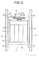
- Fig. 2 is a front view showing the car 2 of Fig. 1 .
- a pair of guide rails 11 are installed within the hoistway 1.
- the car 2 is disposed between the guide rails 11.
- Guide devices 12, each of which is guided by the guide rail 11, are provided on an upper portion of the car 2 and a lower portion of the car 2, respectively.
- the guide devices 12 are guided by the guide rails 11, the car 2 is thereby raised/lowered along the guide rails 11.
- the car 2 has a car chamber 13, and a car frame 14 for supporting the car chamber 13.
- the car frame 14 has a lower frame 15 on which the car chamber 13 is laid, an upper frame 16 disposed above the car chamber 13, and a pair of longitudinal frames 17 for coupling ends of the lower frame 15 to ends of the upper frame 16, respectively.
- the main rope group 10 includes a plurality (a pair in this example) of main ropes 18 and 19.
- the main ropes 18 and 19 are subjected to a terminal treatment at ends thereof by main rope stopper clasps (terminal clasps) 20.
- a cleat device 21 for fastening the end of the main rope 18 of the main ropes 18 and 19 to the car 2 and a cleat device 22 for fastening the end of the other main rope 19 to the car 2 are provided on the upper frame 16, that is, on the upper portion of the car 2.
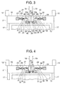
- Fig. 3 is a front view showing the upper portion of the car 2 of Fig. 2 .
- the cleat devices 21 and 22 are horizontally disposed adjacent to each other.
- the ends of the main ropes 18 and 19 are disposed between the cleat devices 21 and 22.
- the ends of the main ropes 18 and 19 and the cleat devices 21 and 22 are disposed between a pair of receiving members 23 and 24 provided on the upper frame 16.
- One of the cleat devices 21 has a turning lever 25 turnable with respect to the car 2, a displacement body 26 connected to the turning lever 25 to be displaced horizontally with respect to the car 2 through the turning of the turning lever 25, and an urging spring (urging body) 27 contracted between the displacement body 26 and the receiving member 23 to generate an elastic restoring force.
- the turning lever 25 is turnable around a support shaft 28 provided on the upper frame 16.
- the turning lever 25 has a main rope mounting portion 25a located on the cleat device 22 side with respect to the support shaft 28 (i.e., on the other side of receiving member 23 side with respect to support shaft 28), and a displacement body mounting portion 25b located above the support shaft 28. That one of the terminal clasps 20 which is provided at the end of the main rope 18 is connected to the main rope mounting portion 25a by a pin 29.
- the displacement body 26 is connected at one end thereof to the displacement body mounting portion 25b by another pin 29.
- the turning lever 25 is turned in such a direction that the main rope mounting portion 25a is displaced upward (counterclockwise in Fig. 3 ) through downward displacement of the car 2 with respect to the end of the main rope 18, and in such a direction that the main rope mounting portion 25a is displaced downward (clockwise in Fig. 3 ) through upward displacement of the car 2 with respect to the end of the main rope 18.
- the displacement body 26 is displaced toward the receiving member 23 through the turning of the turning lever 25 in such a direction that the main rope mounting portion 25a is displaced upward, and away from the receiving member 23 through the turning of the turning lever 25 in such a direction that the main rope mounting portion 25a is displaced downward.
- the displacement body 26 has a rod (displacement body main unit) 30 connected to the displacement body mounting portion 25b, an adjustment member (spring bracket) 31 provided on the rod 30 and designed to be adjustable in position horizontally (in the direction of displacement of displacement body 26) with respect to the rod 30, and a double nut (positioning device) 32 screwed on the rod 30 to fix the adjustment member 31 in position (i.e., to position adjustment member 31) with respect to the rod 30.
- the urging spring 27 is contracted between the adjustment member 31 and the receiving member 23. That is, the urging spring 27 urges the displacement body 26 in such a direction as to act against displacement of the displacement body 26 toward the receiving member 23 (i.e., in such a direction as to act against downward displacement of car 2 with respect to the end of main rope 18).
- the rod 30 receives an urging force of the urging spring 27 as a compressive force.
- the receiving member 23 receives from the urging spring 27 a reactive force of the urging force applied to the displacement body 26.
- the urging force of the urging spring 27 is adjusted by adjusting the position of the adjustment member 31 with respect to the rod 30.
- the tensile force of the main rope 18 is adjusted by adjusting the urging force of the urging spring 27.
- the other cleat device 22 has a turning lever 33 turnable with respect to the car 2, a displacement body 34 connected to the turning lever 33 to be displaced horizontally with respect to the car 2 through the turning of the turning lever 33, and an urging spring (urging body) 35 contracted between the displacement body 34 and the receiving member 24 to generate an elastic restoring force.
- the turning lever 33 is turnable around a support shaft 36 provided on the upper frame 16.
- the turning lever 33 has a main rope mounting portion 33a located on the cleat device 21 side with respect to the support shaft 36 (i.e., on the other side of receiving member 24 side with respect to support shaft 36), and a displacement body mounting portion 33b located above the support shaft 36. That one of the terminal clasps 20 which is provided at the end of the main rope 19 is connected to the main rope mounting portion 33a by a pin 29.
- the displacement body 34 is connected at one end thereof to the displacement body mounting portion 33b by another pin 29.
- the turning lever 33 is turned in such a direction that the main rope mounting portion 33a is displaced upward (clockwise in Fig. 3 ) through downward displacement of the car 2 with respect to the end of the main rope 19, and in such a direction that the main rope mounting portion 33a is displaced downward (counterclockwise in Fig. 3 ) through upward displacement of the car 2 with respect to the end of the main rope 19.
- the displacement body 34 is displaced toward the receiving member 24 through the turning of the turning lever 33 in such a direction that the main rope mounting portion 33a is displaced upward, and away from the receiving member 24 through the turning of the turning lever 33 in such a direction that the main rope mounting portion 33a is displaced downward.
- the displacement body 34 has a rod (displacement body main unit) 37 connected to the displacement body mounting portion 33b and disposed horizontally, an adjustment member (spring bracket) 38 provided on the rod 37 and designed to be adjustable in position horizontally (in direction of displacement of displacement body 34) with respect to the rod 37, and a double nut (positioning device) 39 screwed on the rod 37 to fix the adjustment member 38 in position (i.e., to position adjustment member 38) with respect to the rod 37.
- the urging spring 35 is contracted between the adjustment member 38 and the receiving member 24. That is, the urging spring 35 urges the displacement body 34 in such a direction as to act against displacement of the displacement body 34 toward the receiving member 24 (i.e., in such a direction as to act against downward displacement of car 2 with respect to the end of main rope 19).
- the rod 37 receives an urging force of the urging spring 35 as a compressive force.
- the receiving member 24 receives from the urging spring 35 a reactive force of the urging force applied to the displacement body 34.
- the urging force of the urging spring 35 is adjusted by adjusting the position of the adjustment member 38 with respect to the rod 37.
- the tensile force of the main rope 19 is adjusted by adjusting the urging force of the urging spring 35.
- the pins 29 are each provided with a retainer 40 for preventing disconnection.
- Fig. 4 is a front view showing the cleat devices 21 and 22 at the time when the tensile forces of the main ropes 18 and 19 of Fig. 3 are adjusted.
- the position of the adjustment member 31 with respect to the rod 30 and the position of the adjustment member 38 with respect to the rod 37 are adjusted to equalize the tensile forces of the main ropes 18 and 19 with each other.
- the main rope 18 is longer than the main rope 19, and the tensile forces of the main ropes 18 and 19 are equal to each other when the position of the end of the main rope 18 with respect to the car 2 is lower than the position of the end of the main rope 19 with respect to the car 2.
- the turning lever 25 is turned through vertical displacement of the car 2 with respect to the end of the main rope 18, the displacement body 26 is displaced horizontally through the turning of the turning lever 25, and the urging spring 27 urges the displacement body 26 in such a direction as to act against downward displacement of the car 2 with respect to the end of the main rope 18. Therefore, the displacement body 26 and the urging spring 27 can be disposed horizontally, so the dimension of the cleat device 21 in the height direction thereof can be reduced. The dimension of the terminal clasp 20 provided at the end of the main rope 18 can also be reduced.
- the amounts of protrusion of the cleat device 21 and the terminal clasp 20 from the upper frame 16 can be reduced, so the dimension of the car 2 in the height direction thereof can be reduced. Further, the main rope 18 is not bent due to horizontal disposition of the displacement body 26 and the urging spring 27, so the life of the main rope 18 can be prolonged as well.
- the displacement body 26 has the rod 30 connected to the turning lever 25, and the adjustment member 31 provided on the rod 30 and designed to be adjustable in position horizontally with respect to the rod 30, and the urging force of the urging spring 27 is adjusted by adjusting the position of the adjustment member 31 with respect to the rod 30. Therefore, even when the position of the adjustment member 31 with respect to the rod 30 is changed to adjust the tensile force of the main rope 18, only the position of the adjustment member 31 changes horizontally, and the dimension of the cleat device 21 in the height direction thereof does not change. Accordingly, the dimension of the car 2 in the height direction thereof can be reduced.
- the displacement body 26 receives an urging force of the urging spring 27 as a compressive force. Therefore, the urging body 27 and the displacement body 26 can be disposed side by side horizontally, so the dimension of the cleat device 21 in the height direction thereof can be prevented from increasing.
- the cleat device 22 also achieves the same effect as the cleat device 21.
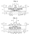
- Fig. 5 is a front view showing a suspension device for an elevator according to Embodiment 2 of the present invention.
- the turning lever 25 has a main rope mounting portion 25a to which the end of the main rope 18 is connected, and a displacement body mounting portion 25b to which one end of the displacement body 26 is connected.
- the main rope mounting portion 25a is located on the cleat device 22 side with respect to the support shaft 28 (on the other side of receiving member 23 side with respect to support shaft 28).
- the displacement body mounting portion 25b is located below the support shaft 28.
- the receiving member 23 is disposed between the adjustment member 31 and the turning lever 25.
- the rod 30 penetrates the receiving member 23.
- the rod 30 is displaceable horizontally with respect to the receiving member 23.
- the urging spring 27 is contracted between the adjustment member 31 and the receiving member 23.
- the turning lever 25 is turned in such a direction that the main rope mounting portion 25a is displaced upward through downward displacement of the car 2 with respect to the end of the main rope 18, and in such a direction that the main rope mounting portion 25a is displaced downward through upward displacement of the car 2 with respect to the end of the main rope 18.
- the displacement body 26 is displaced toward the receiving member 23 through the turning of the turning lever 25 in such a direction that the main rope mounting portion 25a is displaced upward, and away from the receiving member 23 through the turning of the turning lever 25 in such a direction that the main rope mounting portion 25a is displaced downward.
- the urging spring 27 urges the displacement body 26 in such a direction as to act against displacement of the displacement body 26 toward the receiving member 23 (i.e., in such a direction as to act against downward displacement of car 2 with respect to the end of main rope 18).
- the rod 30 receives an urging force of the urging spring 27 as a tensile force.
- the receiving member 23 receives from the urging spring 27 a reactive force of the urging force applied to the displacement body 26.
- the turning lever 33 has the main rope mounting portion 33a to which the end of the main rope 19 is connected, and the displacement body mounting portion 33b to which one end of the displacement body 34 is connected.
- the main rope mounting portion 33a is located on the cleat device 21 side with respect to the support shaft 36 (i.e., on the other side of receiving member 24 side with respect to support shaft 36).
- the displacement bodymounting portion 33b is located below the support shaft 36.
- the receiving member 24 is disposed between the adjustment member 38 and the turning lever 33.
- the rod 37 penetrates the receiving member 24.
- the rod 37 is displaceable horizontally with respect to the receiving member 24.
- the urging spring 35 is contracted between the adjustment member 38 and the receiving member 24.
- the turning lever 33 is turned in such a direction that the main rope mounting portion 33a is displaced upward through downward displacement of the car 2 with respect to the end of the main rope 19, and in such a direction that the main rope mounting portion 33a is displaced downward through upward displacement of the car 2 with respect to the end of the main rope 19.
- the displacement body 34 is displaced toward the receiving member 24 through the turning of the turning lever 33 in such a direction that the main rope mounting portion 33a is displaced upward, and away from the receiving member 24 through the turning of the turning lever 33 in such a direction that the main rope mounting portion 33a is displaced downward.
- the urging spring 35 urges the displacement body 34 in such a direction as to act against displacement of the displacement body 34 toward the receiving member 24 (i.e., in such a direction as to act against downward displacement of car 2 with respect to the end of main rope 19).
- the rod 37 receives an urging force of the urging spring 35 as a tensile force.
- the receiving member 24 receives from the urging spring 35 a reactive force of the urging force applied to the displacement body 34.
- Embodiment 2 of the present invention is identical to Embodiment 1 of the present invention in other constructional details.
- the displacement body 34 receives an urging force of the urging spring 27 as a tensile force. Therefore, the dimension of the cleat device 21 in the height direction thereof can be prevented from increasing, and horizontal displacement of the displacement body 26 can be stabilized.
- the cleat device 22 also achieves the same effect as the cleat device 21.
- Fig. 6 is a front view showing a suspension device for an elevator according to Embodiment 3 of the present invention.
- the turning levers 25 and 33 are turnable around a common support shaft 45 provided on the upper frame 16.
- the support shaft 45 is disposed between the ends of the main ropes 18 and 19.
- the turning lever 25 has the main rope mounting portion 25a to which the end of the main rope 18 is connected, and the displacement body mounting portion 25b to which one end of the displacement body 26 is connected.
- the main rope mounting portion 25a is located on the cleat device 22 side with respect to the support shaft 45 (on the other side of receiving member 23 side with respect to support shaft 45).
- the displacement body mounting portion 25b is located below the support shaft 45.
- the turning lever 33 has the main rope mounting portion 33a to which the end of the main rope 19 is connected, and the displacement body mounting portion 33b to which one end of the displacement body 34 is connected.
- the main rope mounting portion 33a is located on the cleat device 21 side with respect to the support shaft 45 (on the other side of receiving member 24 side with respect to support shaft 45).
- the displacement body mounting portion 33b is located below the support shaft 45.
- Embodiment 3 of the present invention is identical to Embodiment 2 of the present invention in other constructional details.
- the turning levers 25 and 33 are turnable around the common support shaft 45. Therefore, the number of parts can be reduced, so a structural complication and a rise in cost can be prevented.
- the turning levers 25 and 33 in Embodiment 2 of the present invention are turnable around the common support shaft 45.
- the turning levers 25 and 33 in Embodiment 1 of the present invention may be turnable around a common support shaft.
- Fig. 7 is a perspective view showing an elevator according to Embodiment 4 of the present invention.
- the hoisting machine 6 has the hoisting machine body 8, a first drive sheave 51, and a second drive sheave 52.
- the first drive sheave 51 and the second drive sheave 52 are rotated by the hoisting machine body 8.
- the hoisting machine body 8 is disposed between the first drive sheave 51 and the second drive sheave 52.
- the first drive sheave 51 and the second drive sheave 52 are rotated around a common rotaryshaft.
- a first deflector pulley 53 is provided in the vicinity of the first drive sheave 51, and a second deflector pulley 54 is provided in the vicinity of the second drive sheave 52.
- main ropes 18 and 19 are suspended by the main ropes 18 and 19.
- Fig. 8 is a front view showing the upper portion of the car 2 of Fig. 7 .
- the ends of the main ropes 18 and 19 are disposed horizontally apart from each other.
- the cleat devices 21 and 22 are disposed between the ends of the main ropes 18 and 19.
- the cleat devices 21 and 22 are disposed such that the position of the main rope mounting portion 25a with respect to the support shaft 28 and the position of the main rope mounting portion 33a with respect to the support shaft 36 are located horizontally on the other side of each other.
- the cleat devices 21 and 22 are disposed such that the position of the displacement body mounting portion 25b with respect to the support shaft 28 and the position of the displacement body mounting portion 33b with respect to the support shaft 36 are located vertically on the same side.
- the displacement bodies 26 and 34 are displaced in opposite directions through vertical displacement of the car 2 with respect to the ends of the main ropes 18 and 19, respectively.
- the main rope mounting portions 25a and 33a protrude away from each other from the support shafts 28 and 36, respectively, and the displacement body mounting portions 25b and 33b protrude above the support shafts 28 and 36, respectively.
- the displacement bodies 26 and 34 are displaced toward each other through downward displacement of the car 2 with respect to the ends of the main ropes 18 and 19, respectively, and away from each other through upward displacement of the car 2 with respect to the ends of the main ropes 18 and 19, respectively.
- a common receiving member 55 coupled to the displacement bodies 26 and 34 via the respective urging springs 27 and 35 is provided between the cleat devices 21 and 22. That is, the receiving member 55 receives from the urging springs 27 and 35 a reactive force of an urging force applied to the displacement body 26 and a reactive force of an urging force applied to the displacement body 34, respectively.
- the receiving member 55 is displaceable horizontally with respect to the car 2.
- Embodiment 4 of the present invention is identical to Embodiment 1 of the present invention in other constructional details.
- the car 2 is provided with the common receiving member 55 coupled to the displacement bodies 26 and 34 via the respective urging springs 27 and 35, and the receiving member 55 is displaceable horizontally with respect to the car 2. Therefore, the urging forces of the urging springs 27 and 35 are equal to each other, so the tensile forces of the main ropes 18 and 19 can be prevented from being biased against each other. Accordingly, even in the case where passengers gather at a corner of the car chamber 13 and a biased load is applied to the car 2, the tensile forces of the main ropes 18 and 19 can be prevented from being biased against each other.
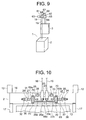
- Fig. 9 is a perspective view showing an elevator according to Embodiment 5 of the present invention.
- the car 2 and the counterweight 3 are raised/lowered within the hoistway 1 due to driving forces of a first hoisting machine 61 and a second hoisting machine 62.
- the first hoisting machine 61 has a hoisting machine body 63, and a first drive sheave 64 that is rotated by the hoisting machine body 63.
- the second hoisting machine 62 has a hoisting machine body 65, and a second drive sheave 66 that is rotated by the hoisting machine body 65.
- the first drive sheave 64 and the second drive sheave 66 are controlled to be rotated in synchronization with each other.
- the first hoisting machine 61 and the second hoisting machine 62 are disposed with the first drive sheave 64 and the second drive sheave 66 facing each other, respectively.
- a first deflector pulley 67 is provided in the vicinity of the first drive sheave 64
- a second deflector pulley 68 is provided in the vicinity of the second drive sheave 66.
- main rope 18 is looped around the first drive sheave 64 and the first deflector pulley 67.
- the other main rope 19 is looped around the second drive sheave 66 and the second deflector pulley 68.
- the car 2 and the counterweight 3 are suspended by the main ropes 18 and 19.
- Fig. 10 is a front view showing the upper portion of the car 2 of Fig. 9 .
- a common receiving member 69 coupled to the displacement bodies 26 and 34 via the respective urging springs 27 and 35 is provided on the upper frame 16.
- the receiving member 69 is displaceable horizontally with respect to the car 2.
- Guide members 70 for guiding horizontal displacement of the receiving member 69 are provided on the upper frame 16.
- the receiving member 69 has a first receiving portion 69a disposed between the turning lever 25 and the adjustment member 31, a second receiving portion 69b disposed between the turning lever 33 and the adjustment member 38, and a joint portion 69c for joining the first receiving portion 69a and the second receiving portion 69b to each other while bypassing the turning levers 25 and 33.
- the rod 30 displaceably penetrates the first receiving portion 69a
- the rod 37 displaceably penetrates the second receiving portion 69b.
- the guide members 70 are a plurality of protrusion members disposed above and below the receiving member 69.
- the receiving member 69 is slid along the protrusion members to be guided horizontally.
- Embodiment 5 of the present invention is identical to Embodiment 2 of the present invention in other constructional details.
- the car 2 is provided with the common receiving member 69 coupled to the displacement bodies 26 and 34 via the respective urging springs 27 and 35, and the receiving member 69 is displaceable horizontally with respect to the car 2. Therefore, the urging forces of the urging springs 27 and 35 are equal to each other, so the tensile forces of the main ropes 18 and 19 can be prevented from being biased against each other.
- the tensile forces of the main ropes 18 and 19 can be prevented from being biased against each other, so a load can be prevented from being biased toward one of the first hoisting machine 61 and the second hoisting machine 62.
- the cleat devices 21 and 22 are provided on the car 2.
- the cleat devices 21 and 22 may be provided on the counterweight 3.
Landscapes
- Engineering & Computer Science (AREA)
- Civil Engineering (AREA)
- Mechanical Engineering (AREA)
- Structural Engineering (AREA)
- Lift-Guide Devices, And Elevator Ropes And Cables (AREA)
Abstract
Description
- The present invention relates to a suspension device for an elevator, which serves to suspend a raised/lowered body such as a car.
- Conventionally, with a view to reducing the height dimension of a car, there is proposed a coupling device for an elevator main rope which is structured such that a guide roller for deflecting the main rope horizontally is provided on an upper portion of the car and that a thimble rod provided at an end of the main rope is installed horizontally on the car (see Patent Document 1).
- Patent Document 1:
JP 2005-212941 A - However, the main rope is constantly bent by the guide roller, so the life of the main rope is shortened.
- The present invention has been made to solve the above-mentioned problem, and it is therefore an object of the present invention to provide a suspension device for an elevator, which makes it possible to reduce the dimension of a raised/lowered body in a height direction thereof and prolong the life of a main rope for suspending the raised/lowered body.
- A suspension device for an elevator according to the present invention includes: a main rope for suspending a raised/lowered body; and a cleat device provided on the raised/lowered body and having a turning lever having connected thereto an end of the main rope to be turned with respect to the raised/lowered body through vertical displacement of the raised/lowered body with respect to the end of the main rope, a displacement body that is horizontally displaced with respect to the raised/lowered body through turning of the turning lever, and an urging body for urging the displacement body in such a direction as to act against downward displacement of the raised/lowered body with respect to the end of the main rope.
-
-
Fig. 1 is a schematic diagram showing an elevator according toEmbodiment 1 of the present invention. -
Fig. 2 is a front view showing the car ofFig. 1 . -
Fig. 3 is a front view showing the upper portion of the car ofFig. 2 . -
Fig. 4 is a front view showing the cleat devices at the time when the tensile forces of the main ropes ofFig. 3 are adjusted. -
Fig. 5 is a front view showing a suspension device for an elevator according toEmbodiment 2 of the present invention. -
Fig. 6 is a front view showing a suspension device for an elevator according toEmbodiment 3 of the present invention. -
Fig. 7 is a perspective view showing an elevator according toEmbodiment 4 of the present invention. -
Fig. 8 is a front view showing the upper portion of the car ofFig. 7 . -
Fig. 9 is a perspective view showing an elevator according toEmbodiment 5 of the present invention. -
Fig. 10 is a front view showing the upper portion of the car ofFig. 9 . - Preferred embodiments of the present invention will be described hereinafter with reference to the drawings.
-
Fig. 1 is a schematic diagram showing an elevator according toEmbodiment 1 of the present invention. Referring toFig. 1 , a car (raised/lowered body) 2 and a counterweight (raised/lowered body) 3 are provided in a manner enabling the raising/lowering thereof within ahoistway 1. Asupport pedestal 5 is provided within amachine room 4 provided in an upper portion of thehoistway 1. A hoistingmachine 6 serving as a drive device and a deflector pulley 7 are supported on thesupport pedestal 5. - The hoisting
machine 6 has a hoistingmachine body 8 including a motor, and adrive sheave 9 that is rotated by the hoistingmachine body 8. Amain rope group 10 for suspending thecar 2 and thecounterweight 3 is looped around thedrive sheave 9 and the deflector pulley 7. Thecar 2 and thecounterweight 3 are raised/lowered within thehoistway 1 through rotation of thedrive sheave 9. -
Fig. 2 is a front view showing thecar 2 ofFig. 1 . Referring toFig. 2 , a pair ofguide rails 11 are installed within thehoistway 1. Thecar 2 is disposed between theguide rails 11.Guide devices 12, each of which is guided by theguide rail 11, are provided on an upper portion of thecar 2 and a lower portion of thecar 2, respectively. When theguide devices 12 are guided by theguide rails 11, thecar 2 is thereby raised/lowered along theguide rails 11. - The
car 2 has acar chamber 13, and acar frame 14 for supporting thecar chamber 13. Thecar frame 14 has alower frame 15 on which thecar chamber 13 is laid, anupper frame 16 disposed above thecar chamber 13, and a pair oflongitudinal frames 17 for coupling ends of thelower frame 15 to ends of theupper frame 16, respectively. - The
main rope group 10 includes a plurality (a pair in this example) ofmain ropes main ropes cleat device 21 for fastening the end of themain rope 18 of themain ropes car 2 and acleat device 22 for fastening the end of the othermain rope 19 to thecar 2 are provided on theupper frame 16, that is, on the upper portion of thecar 2. -
Fig. 3 is a front view showing the upper portion of thecar 2 ofFig. 2 . Referring toFig. 3 , thecleat devices main ropes cleat devices main ropes cleat devices members upper frame 16. - One of the
cleat devices 21 has aturning lever 25 turnable with respect to thecar 2, adisplacement body 26 connected to theturning lever 25 to be displaced horizontally with respect to thecar 2 through the turning of theturning lever 25, and an urging spring (urging body) 27 contracted between thedisplacement body 26 and the receivingmember 23 to generate an elastic restoring force. - The turning
lever 25 is turnable around asupport shaft 28 provided on theupper frame 16. The turninglever 25 has a mainrope mounting portion 25a located on thecleat device 22 side with respect to the support shaft 28 (i.e., on the other side of receivingmember 23 side with respect to support shaft 28), and a displacementbody mounting portion 25b located above thesupport shaft 28. That one of theterminal clasps 20 which is provided at the end of themain rope 18 is connected to the mainrope mounting portion 25a by apin 29. Thedisplacement body 26 is connected at one end thereof to the displacementbody mounting portion 25b by anotherpin 29. - The turning
lever 25 is turned in such a direction that the mainrope mounting portion 25a is displaced upward (counterclockwise inFig. 3 ) through downward displacement of thecar 2 with respect to the end of themain rope 18, and in such a direction that the mainrope mounting portion 25a is displaced downward (clockwise inFig. 3 ) through upward displacement of thecar 2 with respect to the end of themain rope 18. - The
displacement body 26 is displaced toward the receivingmember 23 through the turning of theturning lever 25 in such a direction that the mainrope mounting portion 25a is displaced upward, and away from the receivingmember 23 through the turning of the turninglever 25 in such a direction that the mainrope mounting portion 25a is displaced downward. - The
displacement body 26 has a rod (displacement body main unit) 30 connected to the displacementbody mounting portion 25b, an adjustment member (spring bracket) 31 provided on therod 30 and designed to be adjustable in position horizontally (in the direction of displacement of displacement body 26) with respect to therod 30, and a double nut (positioning device) 32 screwed on therod 30 to fix theadjustment member 31 in position (i.e., to position adjustment member 31) with respect to therod 30. - The urging
spring 27 is contracted between theadjustment member 31 and the receivingmember 23. That is, theurging spring 27 urges thedisplacement body 26 in such a direction as to act against displacement of thedisplacement body 26 toward the receiving member 23 (i.e., in such a direction as to act against downward displacement ofcar 2 with respect to the end of main rope 18). Thus, therod 30 receives an urging force of the urgingspring 27 as a compressive force. The receivingmember 23 receives from the urging spring 27 a reactive force of the urging force applied to thedisplacement body 26. - The urging force of the urging
spring 27 is adjusted by adjusting the position of theadjustment member 31 with respect to therod 30. The tensile force of themain rope 18 is adjusted by adjusting the urging force of the urgingspring 27. - The
other cleat device 22 has aturning lever 33 turnable with respect to thecar 2, adisplacement body 34 connected to theturning lever 33 to be displaced horizontally with respect to thecar 2 through the turning of theturning lever 33, and an urging spring (urging body) 35 contracted between thedisplacement body 34 and the receivingmember 24 to generate an elastic restoring force. - The turning
lever 33 is turnable around asupport shaft 36 provided on theupper frame 16. The turninglever 33 has a mainrope mounting portion 33a located on thecleat device 21 side with respect to the support shaft 36 (i.e., on the other side of receivingmember 24 side with respect to support shaft 36), and a displacementbody mounting portion 33b located above thesupport shaft 36. That one of theterminal clasps 20 which is provided at the end of themain rope 19 is connected to the mainrope mounting portion 33a by apin 29. Thedisplacement body 34 is connected at one end thereof to the displacementbody mounting portion 33b by anotherpin 29. - The turning
lever 33 is turned in such a direction that the mainrope mounting portion 33a is displaced upward (clockwise inFig. 3 ) through downward displacement of thecar 2 with respect to the end of themain rope 19, and in such a direction that the mainrope mounting portion 33a is displaced downward (counterclockwise inFig. 3 ) through upward displacement of thecar 2 with respect to the end of themain rope 19. - The
displacement body 34 is displaced toward the receivingmember 24 through the turning of the turninglever 33 in such a direction that the mainrope mounting portion 33a is displaced upward, and away from the receivingmember 24 through the turning of the turninglever 33 in such a direction that the mainrope mounting portion 33a is displaced downward. - The
displacement body 34 has a rod (displacement body main unit) 37 connected to the displacementbody mounting portion 33b and disposed horizontally, an adjustment member (spring bracket) 38 provided on therod 37 and designed to be adjustable in position horizontally (in direction of displacement of displacement body 34) with respect to therod 37, and a double nut (positioning device) 39 screwed on therod 37 to fix theadjustment member 38 in position (i.e., to position adjustment member 38) with respect to therod 37. - The urging
spring 35 is contracted between theadjustment member 38 and the receivingmember 24. That is, the urgingspring 35 urges thedisplacement body 34 in such a direction as to act against displacement of thedisplacement body 34 toward the receiving member 24 (i.e., in such a direction as to act against downward displacement ofcar 2 with respect to the end of main rope 19). Thus, therod 37 receives an urging force of the urgingspring 35 as a compressive force. The receivingmember 24 receives from the urging spring 35 a reactive force of the urging force applied to thedisplacement body 34. - The urging force of the urging
spring 35 is adjusted by adjusting the position of theadjustment member 38 with respect to therod 37. The tensile force of themain rope 19 is adjusted by adjusting the urging force of the urgingspring 35. Thepins 29 are each provided with aretainer 40 for preventing disconnection. -
Fig. 4 is a front view showing thecleat devices main ropes Fig. 3 are adjusted. As shown inFig. 4 , the position of theadjustment member 31 with respect to therod 30 and the position of theadjustment member 38 with respect to therod 37 are adjusted to equalize the tensile forces of themain ropes main rope 18 is longer than themain rope 19, and the tensile forces of themain ropes main rope 18 with respect to thecar 2 is lower than the position of the end of themain rope 19 with respect to thecar 2. - In the suspension device for the elevator constructed as described above, the turning
lever 25 is turned through vertical displacement of thecar 2 with respect to the end of themain rope 18, thedisplacement body 26 is displaced horizontally through the turning of the turninglever 25, and the urgingspring 27 urges thedisplacement body 26 in such a direction as to act against downward displacement of thecar 2 with respect to the end of themain rope 18. Therefore, thedisplacement body 26 and the urgingspring 27 can be disposed horizontally, so the dimension of thecleat device 21 in the height direction thereof can be reduced. The dimension of theterminal clasp 20 provided at the end of themain rope 18 can also be reduced. Thus, the amounts of protrusion of thecleat device 21 and theterminal clasp 20 from theupper frame 16 can be reduced, so the dimension of thecar 2 in the height direction thereof can be reduced. Further, themain rope 18 is not bent due to horizontal disposition of thedisplacement body 26 and the urgingspring 27, so the life of themain rope 18 can be prolonged as well. - The
displacement body 26 has therod 30 connected to the turninglever 25, and theadjustment member 31 provided on therod 30 and designed to be adjustable in position horizontally with respect to therod 30, and the urging force of the urgingspring 27 is adjusted by adjusting the position of theadjustment member 31 with respect to therod 30. Therefore, even when the position of theadjustment member 31 with respect to therod 30 is changed to adjust the tensile force of themain rope 18, only the position of theadjustment member 31 changes horizontally, and the dimension of thecleat device 21 in the height direction thereof does not change. Accordingly, the dimension of thecar 2 in the height direction thereof can be reduced. - The
displacement body 26 receives an urging force of the urgingspring 27 as a compressive force. Therefore, the urgingbody 27 and thedisplacement body 26 can be disposed side by side horizontally, so the dimension of thecleat device 21 in the height direction thereof can be prevented from increasing. Thecleat device 22 also achieves the same effect as thecleat device 21. -
Fig. 5 is a front view showing a suspension device for an elevator according toEmbodiment 2 of the present invention. Referring toFig. 5 , the turninglever 25 has a mainrope mounting portion 25a to which the end of themain rope 18 is connected, and a displacementbody mounting portion 25b to which one end of thedisplacement body 26 is connected. The mainrope mounting portion 25a is located on thecleat device 22 side with respect to the support shaft 28 (on the other side of receivingmember 23 side with respect to support shaft 28). The displacementbody mounting portion 25b is located below thesupport shaft 28. - The receiving
member 23 is disposed between theadjustment member 31 and the turninglever 25. Therod 30 penetrates the receivingmember 23. Therod 30 is displaceable horizontally with respect to the receivingmember 23. The urgingspring 27 is contracted between theadjustment member 31 and the receivingmember 23. - The turning
lever 25 is turned in such a direction that the mainrope mounting portion 25a is displaced upward through downward displacement of thecar 2 with respect to the end of themain rope 18, and in such a direction that the mainrope mounting portion 25a is displaced downward through upward displacement of thecar 2 with respect to the end of themain rope 18. - The
displacement body 26 is displaced toward the receivingmember 23 through the turning of the turninglever 25 in such a direction that the mainrope mounting portion 25a is displaced upward, and away from the receivingmember 23 through the turning of the turninglever 25 in such a direction that the mainrope mounting portion 25a is displaced downward. - The urging
spring 27 urges thedisplacement body 26 in such a direction as to act against displacement of thedisplacement body 26 toward the receiving member 23 (i.e., in such a direction as to act against downward displacement ofcar 2 with respect to the end of main rope 18). Thus, therod 30 receives an urging force of the urgingspring 27 as a tensile force. The receivingmember 23 receives from the urging spring 27 a reactive force of the urging force applied to thedisplacement body 26. - The turning
lever 33 has the mainrope mounting portion 33a to which the end of themain rope 19 is connected, and the displacementbody mounting portion 33b to which one end of thedisplacement body 34 is connected. The mainrope mounting portion 33a is located on thecleat device 21 side with respect to the support shaft 36 (i.e., on the other side of receivingmember 24 side with respect to support shaft 36). Thedisplacement bodymounting portion 33b is located below thesupport shaft 36. - The receiving
member 24 is disposed between theadjustment member 38 and the turninglever 33. Therod 37 penetrates the receivingmember 24. Therod 37 is displaceable horizontally with respect to the receivingmember 24. The urgingspring 35 is contracted between theadjustment member 38 and the receivingmember 24. - The turning
lever 33 is turned in such a direction that the mainrope mounting portion 33a is displaced upward through downward displacement of thecar 2 with respect to the end of themain rope 19, and in such a direction that the mainrope mounting portion 33a is displaced downward through upward displacement of thecar 2 with respect to the end of themain rope 19. - The
displacement body 34 is displaced toward the receivingmember 24 through the turning of the turninglever 33 in such a direction that the mainrope mounting portion 33a is displaced upward, and away from the receivingmember 24 through the turning of the turninglever 33 in such a direction that the mainrope mounting portion 33a is displaced downward. - The urging
spring 35 urges thedisplacement body 34 in such a direction as to act against displacement of thedisplacement body 34 toward the receiving member 24 (i.e., in such a direction as to act against downward displacement ofcar 2 with respect to the end of main rope 19). Thus, therod 37 receives an urging force of the urgingspring 35 as a tensile force. The receivingmember 24 receives from the urging spring 35 a reactive force of the urging force applied to thedisplacement body 34.Embodiment 2 of the present invention is identical toEmbodiment 1 of the present invention in other constructional details. - In the suspension device for the elevator constructed as described above, the
displacement body 34 receives an urging force of the urgingspring 27 as a tensile force. Therefore, the dimension of thecleat device 21 in the height direction thereof can be prevented from increasing, and horizontal displacement of thedisplacement body 26 can be stabilized. Thecleat device 22 also achieves the same effect as thecleat device 21. -
Fig. 6 is a front view showing a suspension device for an elevator according toEmbodiment 3 of the present invention. Referring toFig. 6 , the turning levers 25 and 33 are turnable around acommon support shaft 45 provided on theupper frame 16. Thesupport shaft 45 is disposed between the ends of themain ropes - The turning
lever 25 has the mainrope mounting portion 25a to which the end of themain rope 18 is connected, and the displacementbody mounting portion 25b to which one end of thedisplacement body 26 is connected. The mainrope mounting portion 25a is located on thecleat device 22 side with respect to the support shaft 45 (on the other side of receivingmember 23 side with respect to support shaft 45). The displacementbody mounting portion 25b is located below thesupport shaft 45. - The turning
lever 33 has the mainrope mounting portion 33a to which the end of themain rope 19 is connected, and the displacementbody mounting portion 33b to which one end of thedisplacement body 34 is connected. The mainrope mounting portion 33a is located on thecleat device 21 side with respect to the support shaft 45 (on the other side of receivingmember 24 side with respect to support shaft 45). The displacementbody mounting portion 33b is located below thesupport shaft 45.Embodiment 3 of the present invention is identical toEmbodiment 2 of the present invention in other constructional details. - In the suspension device for the elevator constructed as described above, the turning levers 25 and 33 are turnable around the
common support shaft 45. Therefore, the number of parts can be reduced, so a structural complication and a rise in cost can be prevented. - In the foregoing example, the turning levers 25 and 33 in
Embodiment 2 of the present invention are turnable around thecommon support shaft 45. However, the turning levers 25 and 33 inEmbodiment 1 of the present invention may be turnable around a common support shaft. -
Fig. 7 is a perspective view showing an elevator according toEmbodiment 4 of the present invention. Referring toFig. 7 , the hoistingmachine 6 has the hoistingmachine body 8, afirst drive sheave 51, and asecond drive sheave 52. Thefirst drive sheave 51 and thesecond drive sheave 52 are rotated by the hoistingmachine body 8. The hoistingmachine body 8 is disposed between thefirst drive sheave 51 and thesecond drive sheave 52. Thefirst drive sheave 51 and thesecond drive sheave 52 are rotated around a common rotaryshaft. Afirst deflector pulley 53 is provided in the vicinity of thefirst drive sheave 51, and asecond deflector pulley 54 is provided in the vicinity of thesecond drive sheave 52. - Of the
main ropes main rope 18 is looped around thefirst drive sheave 51 and thefirst deflector pulley 53. The othermain rope 19 is looped around thesecond drive sheave 52 and thesecond deflector pulley 54. Thecar 2 and thecounterweight 3 are suspended by themain ropes -
Fig. 8 is a front view showing the upper portion of thecar 2 ofFig. 7 . Referring toFig. 8 , the ends of themain ropes cleat devices main ropes - The
cleat devices rope mounting portion 25a with respect to thesupport shaft 28 and the position of the mainrope mounting portion 33a with respect to thesupport shaft 36 are located horizontally on the other side of each other. Thecleat devices body mounting portion 25b with respect to thesupport shaft 28 and the position of the displacementbody mounting portion 33b with respect to thesupport shaft 36 are located vertically on the same side. Thus, thedisplacement bodies car 2 with respect to the ends of themain ropes - In this example, the main
rope mounting portions support shafts body mounting portions support shafts displacement bodies car 2 with respect to the ends of themain ropes car 2 with respect to the ends of themain ropes - A common receiving
member 55 coupled to thedisplacement bodies cleat devices member 55 receives from the urging springs 27 and 35 a reactive force of an urging force applied to thedisplacement body 26 and a reactive force of an urging force applied to thedisplacement body 34, respectively. The receivingmember 55 is displaceable horizontally with respect to thecar 2. - A
tubular guide member 56 for guiding horizontal displacement of the receivingmember 55 is provided on theupper frame 16. The receivingmember 55 is slid within theguide member 56 to be guided horizontally.Embodiment 4 of the present invention is identical toEmbodiment 1 of the present invention in other constructional details. - In the suspension device for the elevator constructed as described above, the
car 2 is provided with the common receivingmember 55 coupled to thedisplacement bodies member 55 is displaceable horizontally with respect to thecar 2. Therefore, the urging forces of the urging springs 27 and 35 are equal to each other, so the tensile forces of themain ropes car chamber 13 and a biased load is applied to thecar 2, the tensile forces of themain ropes -
Fig. 9 is a perspective view showing an elevator according toEmbodiment 5 of the present invention. Referring toFig. 9 , thecar 2 and thecounterweight 3 are raised/lowered within thehoistway 1 due to driving forces of afirst hoisting machine 61 and asecond hoisting machine 62. Thefirst hoisting machine 61 has a hoistingmachine body 63, and afirst drive sheave 64 that is rotated by the hoistingmachine body 63. Thesecond hoisting machine 62 has a hoistingmachine body 65, and asecond drive sheave 66 that is rotated by the hoistingmachine body 65. Thefirst drive sheave 64 and thesecond drive sheave 66 are controlled to be rotated in synchronization with each other. - The
first hoisting machine 61 and thesecond hoisting machine 62 are disposed with thefirst drive sheave 64 and thesecond drive sheave 66 facing each other, respectively. Afirst deflector pulley 67 is provided in the vicinity of thefirst drive sheave 64, and asecond deflector pulley 68 is provided in the vicinity of thesecond drive sheave 66. - Of the
main ropes main rope 18 is looped around thefirst drive sheave 64 and thefirst deflector pulley 67. The othermain rope 19 is looped around thesecond drive sheave 66 and thesecond deflector pulley 68. Thecar 2 and thecounterweight 3 are suspended by themain ropes -
Fig. 10 is a front view showing the upper portion of thecar 2 ofFig. 9 . Referring toFig. 10 , a common receiving member 69 coupled to thedisplacement bodies upper frame 16. The receiving member 69 is displaceable horizontally with respect to thecar 2.Guide members 70 for guiding horizontal displacement of the receiving member 69 are provided on theupper frame 16. - The receiving member 69 has a
first receiving portion 69a disposed between the turninglever 25 and theadjustment member 31, asecond receiving portion 69b disposed between the turninglever 33 and theadjustment member 38, and a joint portion 69c for joining the first receivingportion 69a and thesecond receiving portion 69b to each other while bypassing the turning levers 25 and 33. Therod 30 displaceably penetrates the first receivingportion 69a, and therod 37 displaceably penetrates thesecond receiving portion 69b. - The
guide members 70 are a plurality of protrusion members disposed above and below the receiving member 69. The receiving member 69 is slid along the protrusion members to be guided horizontally.Embodiment 5 of the present invention is identical toEmbodiment 2 of the present invention in other constructional details. - In the suspension device for the elevator constructed as described above, the
car 2 is provided with the common receiving member 69 coupled to thedisplacement bodies car 2. Therefore, the urging forces of the urging springs 27 and 35 are equal to each other, so the tensile forces of themain ropes first drive sheave 64 and thesecond drive sheave 66 rotate out of synchronization with each other, the tensile forces of themain ropes first hoisting machine 61 and thesecond hoisting machine 62. - In each of the aforementioned embodiments of the present invention, the
cleat devices car 2. However, thecleat devices counterweight 3.
Claims (6)
- A suspension device for an elevator, comprising:a main rope for suspending a raised/lowered body; anda cleat device provided on the raised/lowered body and havinga turning lever having connected thereto an end of the main rope to be turned with respect to the raised/lowered body through vertical displacement of the raised/lowered body with respect to the end of the main rope,a displacement body that is horizontally displaced with respect to the raised/lowered body through turning of the turning lever, andan urging body for urging the displacement body in such a direction as to act against downward displacement of the raised/lowered body with respect to the end of the main rope.
- A suspension device for an elevator according to Claim 1, wherein:the displacement body comprisesa displacement body main unit connected to the turning lever, andan adjustment member provided on the displacement body main unit and being adjustable in position horizontally with respect to the displacement body main unit; andthe urging body exerts an urging force that is adjusted by adjusting a position of the adjustment member with respect to the displacement body main unit.
- A suspension device for an elevator according to Claim 1, wherein the displacement body receives an urging force of the urging body as a compressive force.
- A suspension device for an elevator according to Claim 1, wherein the displacement body receives an urging force of the urging body as a tensile force.
- A suspension device for an elevator according to any one of Claims 1 to 4, wherein:the raised/lowered body is suspended by a plurality of main ropes identical to the main rope;the raised/lowered body is provided with a plurality of cleat devices identical to the cleat device to which the main ropes are connected; andthe turning lever of each of the plurality of cleat devices is turnable around a common support shaft.
- A suspension device for an elevator according to any one of Claims 1 to 4, wherein:the raised/lowered body is suspended by a pair of main ropes identical to the main rope;the cleat device, to which one of the main ropes is connected, and the cleat device, to which the other of the main ropes is connected, are disposed so that the displacement body of the former cleat device and the displacement body of the latter cleat device are displaced in opposite directions through vertical displacement of the raised/lowered body with respect to ends of the pair of the main ropes;the raised/lowered body is provided with a common receiving member coupled to the displacement bodies via the urging body of the former cleat device and the urging body of the latter cleat device, respectively; andthe receiving member is displaceable horizontally with respect to the raised/lowered body.
Applications Claiming Priority (1)
| Application Number | Priority Date | Filing Date | Title |
|---|---|---|---|
| PCT/JP2006/304333 WO2007102196A1 (en) | 2006-03-07 | 2006-03-07 | Suspension device for elevator |
Publications (2)
| Publication Number | Publication Date |
|---|---|
| EP1992582A1 true EP1992582A1 (en) | 2008-11-19 |
| EP1992582A4 EP1992582A4 (en) | 2013-03-13 |
Family
ID=38474645
Family Applications (1)
| Application Number | Title | Priority Date | Filing Date |
|---|---|---|---|
| EP06728702A Withdrawn EP1992582A4 (en) | 2006-03-07 | 2006-03-07 | SUSPENSION DEVICE FOR ELEVATOR |
Country Status (5)
| Country | Link |
|---|---|
| EP (1) | EP1992582A4 (en) |
| JP (1) | JP5079495B2 (en) |
| KR (1) | KR101012254B1 (en) |
| CN (1) | CN101321680A (en) |
| WO (1) | WO2007102196A1 (en) |
Cited By (2)
| Publication number | Priority date | Publication date | Assignee | Title |
|---|---|---|---|---|
| WO2012175807A1 (en) * | 2011-06-22 | 2012-12-27 | Kone Corporation | Tensioning arrangement for a traction means of an elevator |
| CN103287948A (en) * | 2012-03-02 | 2013-09-11 | 株式会社日立制作所 | Space-saving elevator |
Families Citing this family (2)
| Publication number | Priority date | Publication date | Assignee | Title |
|---|---|---|---|---|
| CN102241353A (en) * | 2010-05-13 | 2011-11-16 | 北京安泰通达电梯服务有限公司 | Home elevator |
| JP7771826B2 (en) * | 2022-03-17 | 2025-11-18 | 三菱電機株式会社 | Elevator rope device |
Family Cites Families (7)
| Publication number | Priority date | Publication date | Assignee | Title |
|---|---|---|---|---|
| GB551193A (en) * | 1941-11-03 | 1943-02-11 | Asea Electric Ltd | Improvements in, or relating to, hoists, cranes, lifts and the like lifting apparatus |
| JPS4924142Y1 (en) * | 1970-12-26 | 1974-06-28 | ||
| JPS5247394Y2 (en) * | 1972-05-31 | 1977-10-27 | ||
| JPS59133571U (en) * | 1983-02-23 | 1984-09-06 | フジテック株式会社 | Elevator balance compensation rope attachment device |
| EP1123891A3 (en) * | 2000-02-09 | 2002-05-02 | Otis Elevator Company | Dead end hitch for elevator rope |
| JP2005212941A (en) * | 2004-01-28 | 2005-08-11 | Hitachi Ltd | Connecting device for elevator main rope |
| EP1780161A4 (en) * | 2004-08-18 | 2012-01-18 | Mitsubishi Electric Corp | LIFT DEVICE |
-
2006
- 2006-03-07 CN CNA2006800450863A patent/CN101321680A/en active Pending
- 2006-03-07 WO PCT/JP2006/304333 patent/WO2007102196A1/en not_active Ceased
- 2006-03-07 EP EP06728702A patent/EP1992582A4/en not_active Withdrawn
- 2006-03-07 KR KR1020087012547A patent/KR101012254B1/en not_active Expired - Fee Related
- 2006-03-07 JP JP2007508202A patent/JP5079495B2/en not_active Expired - Fee Related
Cited By (4)
| Publication number | Priority date | Publication date | Assignee | Title |
|---|---|---|---|---|
| WO2012175807A1 (en) * | 2011-06-22 | 2012-12-27 | Kone Corporation | Tensioning arrangement for a traction means of an elevator |
| US9758346B2 (en) | 2011-06-22 | 2017-09-12 | Kone Corporation | Tensioning arrangement for a traction means of an elevator |
| CN103287948A (en) * | 2012-03-02 | 2013-09-11 | 株式会社日立制作所 | Space-saving elevator |
| CN103287948B (en) * | 2012-03-02 | 2015-11-25 | 株式会社日立制作所 | Save space elevator |
Also Published As
| Publication number | Publication date |
|---|---|
| EP1992582A4 (en) | 2013-03-13 |
| WO2007102196A1 (en) | 2007-09-13 |
| KR101012254B1 (en) | 2011-02-08 |
| CN101321680A (en) | 2008-12-10 |
| KR20080078808A (en) | 2008-08-28 |
| JPWO2007102196A1 (en) | 2009-07-23 |
| JP5079495B2 (en) | 2012-11-21 |
Similar Documents
| Publication | Publication Date | Title |
|---|---|---|
| US8020670B2 (en) | Arrangement for equalizing elevator rope force and elevator | |
| RU2410321C2 (en) | Elevator installation | |
| CN107531456B (en) | Device for adjusting the tightness of an elevator traction means | |
| CN104093657B (en) | Double-deck elevator | |
| JP2012520807A (en) | Elevator load bearing vibration control | |
| JPH04121387A (en) | Elevator device | |
| CA2491551A1 (en) | Drive for a lift installation and method of converting a drive in a lift installation | |
| JP2009173386A (en) | Elevator installation equipment | |
| JP2004115184A (en) | Rope body guiding device for balance compensation of elevator | |
| JP2001039648A (en) | Tension method and device for elevator governor rope | |
| EP1992582A1 (en) | Suspension device for elevator | |
| EP1798184A1 (en) | Rope tension adjester of elevator | |
| JP2023506644A (en) | Drive system for elevator installation, elevator installation and method for installing drive on support elements of elevator installation | |
| EP1123891A2 (en) | Dead end hitch for elevator rope | |
| JP2008222339A (en) | Governor tensioner device for elevator | |
| AU2004291360B2 (en) | Elevator suspension arrangement | |
| MXPA05005630A (en) | Self-centering device for compensation ropes or chains of anelevator. | |
| CN113321100B (en) | Traction machine unit and method for installing same | |
| EP1842821A1 (en) | Balance weight-less elevator apparatus | |
| WO2007074206A1 (en) | Elevator system | |
| KR20240009942A (en) | Drive systems for elevator installations, elevator installations, and methods for installing drives on support elements of elevator installations | |
| CN203699603U (en) | Elevator car suspension structure | |
| CN103863919B (en) | the load bearing beam holding device of elevator | |
| JP4056475B2 (en) | Elevator equipment | |
| JP7827126B1 (en) | Main rope vibration suppression device |
Legal Events
| Date | Code | Title | Description |
|---|---|---|---|
| PUAI | Public reference made under article 153(3) epc to a published international application that has entered the european phase |
Free format text: ORIGINAL CODE: 0009012 |
|
| 17P | Request for examination filed |
Effective date: 20080514 |
|
| AK | Designated contracting states |
Kind code of ref document: A1 Designated state(s): DE |
|
| DAX | Request for extension of the european patent (deleted) | ||
| RBV | Designated contracting states (corrected) |
Designated state(s): DE |
|
| A4 | Supplementary search report drawn up and despatched |
Effective date: 20130213 |
|
| RIC1 | Information provided on ipc code assigned before grant |
Ipc: B66B 7/08 20060101AFI20130207BHEP Ipc: B66B 11/02 20060101ALI20130207BHEP |
|
| STAA | Information on the status of an ep patent application or granted ep patent |
Free format text: STATUS: THE APPLICATION HAS BEEN WITHDRAWN |
|
| 18W | Application withdrawn |
Effective date: 20140212 |