EP1992192B1 - Schallschwamm für lautsprecher - Google Patents
Schallschwamm für lautsprecher Download PDFInfo
- Publication number
- EP1992192B1 EP1992192B1 EP07705595.2A EP07705595A EP1992192B1 EP 1992192 B1 EP1992192 B1 EP 1992192B1 EP 07705595 A EP07705595 A EP 07705595A EP 1992192 B1 EP1992192 B1 EP 1992192B1
- Authority
- EP
- European Patent Office
- Prior art keywords
- diaphragm
- acoustic
- ducts
- loudspeaker system
- multiple ducts
- Prior art date
- Legal status (The legal status is an assumption and is not a legal conclusion. Google has not performed a legal analysis and makes no representation as to the accuracy of the status listed.)
- Active
Links
Images


Classifications
-
- H—ELECTRICITY
- H04—ELECTRIC COMMUNICATION TECHNIQUE
- H04R—LOUDSPEAKERS, MICROPHONES, GRAMOPHONE PICK-UPS OR LIKE ACOUSTIC ELECTROMECHANICAL TRANSDUCERS; ELECTRIC HEARING AIDS; PUBLIC ADDRESS SYSTEMS
- H04R1/00—Details of transducers, loudspeakers or microphones
- H04R1/20—Arrangements for obtaining desired frequency or directional characteristics
- H04R1/22—Arrangements for obtaining desired frequency or directional characteristics for obtaining desired frequency characteristic only
- H04R1/225—Arrangements for obtaining desired frequency or directional characteristics for obtaining desired frequency characteristic only for telephonic receivers
-
- H—ELECTRICITY
- H04—ELECTRIC COMMUNICATION TECHNIQUE
- H04R—LOUDSPEAKERS, MICROPHONES, GRAMOPHONE PICK-UPS OR LIKE ACOUSTIC ELECTROMECHANICAL TRANSDUCERS; ELECTRIC HEARING AIDS; PUBLIC ADDRESS SYSTEMS
- H04R2400/00—Loudspeakers
- H04R2400/11—Aspects regarding the frame of loudspeaker transducers
-
- H—ELECTRICITY
- H04—ELECTRIC COMMUNICATION TECHNIQUE
- H04R—LOUDSPEAKERS, MICROPHONES, GRAMOPHONE PICK-UPS OR LIKE ACOUSTIC ELECTROMECHANICAL TRANSDUCERS; ELECTRIC HEARING AIDS; PUBLIC ADDRESS SYSTEMS
- H04R2420/00—Details of connection covered by H04R, not provided for in its groups
- H04R2420/07—Applications of wireless loudspeakers or wireless microphones
-
- H—ELECTRICITY
- H04—ELECTRIC COMMUNICATION TECHNIQUE
- H04R—LOUDSPEAKERS, MICROPHONES, GRAMOPHONE PICK-UPS OR LIKE ACOUSTIC ELECTROMECHANICAL TRANSDUCERS; ELECTRIC HEARING AIDS; PUBLIC ADDRESS SYSTEMS
- H04R2499/00—Aspects covered by H04R or H04S not otherwise provided for in their subgroups
- H04R2499/10—General applications
- H04R2499/11—Transducers incorporated or for use in hand-held devices, e.g. mobile phones, PDA's, camera's
Definitions
- This invention generally relates to the fields of acoustics and audio transducer technology and more specifically to reducing loudspeaker size by improving its performance using a sound sponge block.
- New loudspeaker technologies are being considered for use in mobile products which have a number of advantages over the moving coil types currently being used, such as potentially higher efficiency, higher quality or greater flexibility regarding product form factor.
- what most of these have in common is very light flexible diaphragms and therefore would not work with, e.g., sealed-cavity design paradigm, since this would provide too much stiffness and therefore greatly reduce the low frequency output.
- An open back design would not be satisfactory either since the sound radiated from the rear would partially cancel the sound radiated from the front because the two are in opposite phase. This appears to be a major technology bottleneck.
- US 4 869 340 describes a loudspeaker enclosure. Going inwardly from the outside, the walls of the housing comprise a multi-ply slab, one or more layers of elastomer coating, a plate of amorphous bitumen, and acoustic screens constituted by substantially contiguous parallel tubes which are filled with a solid material.
- GB 2 329 514 A discloses a loudspeaker which is resistively terminated at the rear with a closely-coupled sound absorber made from an aerogel.
- GB 626 623 A discloses a loudspeaker in which, for absorbing long waves, a roll of corrugated cardboard or the like is placed behind a diaphragm.
- a loudspeaker comprises a diaphragm configured to provide an acoustic signal by a way of vibrations from the loudspeaker in forward and backward directions; and a sound sponge block comprising multiple ducts made of a pre-selected material placed behind the diaphragm without physically touching the diaphragm, wherein the multiple ducts have predetermined geometrical dimensions to substantially absorb the sound waves radiated from a rear side of the diaphragm in the backward direction.
- the multiple ducts may be round cylinders.
- the round cylinders may have a diameter between 0.1 and 10 microns.
- the ends of the multiple ducts furthest from the diaphragm maybe sealed and have an infinite specific termination impedance.
- the multiple ducts may be parallel to each other.
- the multiple ducts may be substantially perpendicular to a surface of the diaphragm.
- a cross section of the multiple ducts may comprise 90% or less of a total cross section area of the sound sponge block.
- an electronic device comprises a signal provider, configured to provide an electric drive signal; and a loudspeaker, responsive to the electric drive signal, configured to provide an acoustic signal of the electronic device in response to the electric drive signal, wherein the loudspeaker comprises: a diaphragm configured to provide the acoustic signal by a way of vibrations from the loudspeaker in forward and backward directions; and a sound sponge block comprising multiple ducts made of a pre-selected material placed behind the diaphragm without physically touching the diaphragm, wherein the multiple ducts have predetermined geometrical dimensions to substantially absorb the sound waves radiated from a rear side of the diaphragm in the backward direction.
- the diaphragm may be made of optically transparent material such that the loudspeaker is combined with a display of the electronic device.
- a method comprises providing an acoustic signal in forward and backward directions by a way of vibrations of a diaphragm of a loudspeaker; and absorbing the sound waves radiated from a rear side of the diaphragm in a backward direction using a sound sponge block comprising multiple ducts made of a pre-selected material placed behind the diaphragm without physically touching the diaphragm, wherein the multiple ducts have predetermined geometrical dimensions to substantially absorb the sound waves.
- the multiple ducts may be round cylinders.
- the round cylinders may have a diameter between 0.1 and 10 microns.
- the ends of the multiple ducts furthest from the diaphragm maybe sealed and have an infinite specific termination impedance.
- the multiple ducts may be parallel to each other.
- the multiple ducts may be substantially perpendicular to a surface of the diaphragm.
- a cross section of the multiple ducts may comprise 90% or less of a total cross section area of the sound sponge block.
- a sound sponge block may have a real part of an acoustic impedance substantially constant in a predetermined frequency range. Further, the frequency range may be from 10 Hz to 10,000 Hz.
- a sound sponge block may have a real part of an acoustic impedance substantially constant in a predetermined frequency range. Further, the frequency range may be from 10 Hz to 10,000 Hz.
- this sound sponge block is an array of narrow ducts (e.g., parallel ducts, or parallel round cylinders of a small diameter) made of a pre-selected material with predetermined dimensions (e.g., the diameter and length) formed within a single block which is placed behind a loudspeaker diaphragm (also called a membrane), but not actually in a direct contact with it.
- the ducts can be made of a rigid etchable material such as (but not limited to) metal, plastic, glass, silicon or ceramic.
- the diaphragm provides an acoustic signal by a way of vibration in forward and backward directions and the sound sponge block, comprising the multiple ducts, substantially absorbs the sound waves radiated from a rear side of the diaphragm in the backward direction due to significant drop in impedance for very narrow tube diameters.
- Very narrow ducts e.g., with duct diameters on the order of a micron, for example, from 0.1 to 10 microns
- the wave propagation speeds of sound are 33 m/s, 3.3 m/s and .33 m/s, respectively.
- the reduction in the propagation speed explains the eventual drop in the impedance for very narrow tube diameters.
- the axes of the ducts can be substantially parallel with the axis of the diaphragm (i.e., the ducts are perpendicular to the surface of the plane diaphragm).
- Dimensions of the ducts e.g., the diameter and length
- the ends of the ducts furthest from the diaphragm can be sealed (blocked) and have infinite specific termination impedance typically using the same material as the ducts themselves. The absorption is achieved through viscous boundary losses and thermal conduction.
- a single cavity provides mainly stiffness which opposes the motion of the diaphragm and therefore has to be large in order to minimize the stiffness.
- the sound wave is slowed down by the viscous and thermal losses so that the impedance falls and becomes mainly resistive which allows to effectively control the diaphragm's resonant modes.
- the overall cavity space can be greatly reduced.
- the loudspeaker with the sound sponge can be used in a variety of electronic devices, which can include (but are not limited to): communication devices, computers, wireless communication devices, portable electronic devices, mobile electronic devices, a mobile phone, etc.
- the main advantage of the sound sponge is that it enables the use of high-efficiency high-quality (i.e. low-distortion and flat frequency response) membrane type loudspeakers in small spaces.
- Current mobile loudspeaker designs are typically 0.01% efficient.
- the sound sponge allows to absorb the lower frequency waves which cannot be accomplished with the prior art sound absorbing porous materials in which the pores are essentially random in size.
- the loudspeaker can be combined with a display of the electronic device, e.g., the loudspeaker could be mounted directly in front of a display and would therefore open up all kinds of industrial design possibilities. Due to the increased efficiency, WLAN (wireless local area network) loudspeakers, for use with music playing phones, could be produced as well. These loudspeakers could run from batteries that would last for a long time.
- WLAN wireless local area network
- Figures 1a and 1b show examples among others of schematic representations of electrodynamic loudspeakers 10 and 10a: a) according to the prior art ( Figure 1a ), and b) with a sound sponge block 18 ( Figure 1b ), according to an embodiment of the present invention.
- a sound sponge block 18 with multiple parallel round ducts 16 in Figure 1b is used for absorbing backward waves radiated by the loudspeaker diaphragm 14 in a backward direction, according to embodiments of the present invention.
- the ends of the ducts 16 furthest from the diaphragm 14 are sealed (blocked) and have infinite specific termination impedance.
- the diaphragm 14 can generally be means for providing an acoustic signal or a structural equivalence (or an equivalent structure) thereof.
- the sound sponge block 18 can generally be means for absorbing or a structural equivalence (or equivalent structure) thereof.
- Figures 2a and 2b show examples among others of schematic representations of electrostatic loudspeakers 20 and 20a: a) according to the prior art, and b) with a sound sponge block 18, according to an embodiment of the present invention.
- a large continuous enclosed cavity 12a is needed for reduction/cancellation of the backward wave effects, which unfortunately reduces the bass response of the loudspeaker 20.
- the sound sponge block 18 with multiple parallel round ducts 16 is used in a partitioned cavity design with much smaller dimensions (L1 ⁇ L) for absorbing backward waves radiated by the loudspeaker flat diaphragm 14a (with electrodes 22a and 22b close to the surfaces of the diaphragm 14a ), in a backward direction, according to embodiments of the present invention.
- the ends of the ducts 16 furthest from the diaphragm 14a are also sealed (blocked) thus having infinite specific termination impedance.
- the diaphragm 14a and the electrodes 22a and 22b are made of the optically transparent materials (e.g., the electrodes can be made of a conducting material such as metal or a non-conductive clear plastic with a conductive transparent coating such as indium tin oxide), the loudspeaker 20a can be combined with a display of the electronic device, as discussed above.
- the electrodes can be made of a conducting material such as metal or a non-conductive clear plastic with a conductive transparent coating such as indium tin oxide
- the loudspeaker 20a can be combined with a display of the electronic device, as discussed above.
- Figure 3 is an example among others of a cross section of a sound sponge block 18, according to an embodiment of the present invention.
- the ducts 16 are round cylinders of a small diameter (typically on the order of microns, e.g., from 0.1 to 10 microns), however, the various embodiments of the present invention can be applied to ducts of larger diameters as well.
- the filling factor of such ducts 16 should be as high as practically possible in order to minimize the impedance.
- the filling factor of 1 ⁇ 2 i.e., half of the cross sectional area of the block 18 comprises the ducts 16
- doubles the specific acoustic impedance For the filling factor of 1/3 (i.e., one third of the cross sectional area of the block 18 comprises the ducts 16 ) triples the specific acoustic impedance.
- Figure 4a and 4b are examples among others of graphs of simulated results for the specific acoustic impedance as a function of frequency of a sound sponge block 18 for: a) round ducts of 1 ⁇ m in diameter and 100 ⁇ m long with a filling factor of one half and b) round ducts of 1.5 ⁇ m in diameter and 500 ⁇ m long also with a filling factor of one half, according to embodiments of the present invention.
- the dominant resistive impedance of 90-100 Rayls shown in Figure 4a is fairly optimum in a broad (e.g., predetermined) frequency range (e.g., from 10 Hz to about 10,000 Hz) especially for an electrostatic loudspeaker 20a shown in Figure 2b , because it provides good damping of the diaphragm vibration modes but does not attenuate the acoustic output in the forward direction.
- the analysis shows that the duct diameter cannot be increased too much further. If it is increased, the duct length has to be increased to achieve the same impedance at 10 Hz, which results in rising the impedance at higher frequencies as shown in Figure 4b (typically the rising impedance is proportional to the square root of the frequency). The results are for the sound sponge with a filling factor of 1 ⁇ 2.
- z T ⁇ ⁇ ⁇ iz 0 cot kL wherein z 0 ⁇ ⁇ ⁇ k 1 ⁇ 2 J 1 a k V 2 ⁇ k 2 k V aJ 0 a k V 2 ⁇ k 2 ⁇ 1 k ⁇ ⁇ c 1 + 2 ⁇ ⁇ 1 J 1 k T a k T aJ 0 k T a 1 + 2 J 1 k V a k V aJ 0 k V a ⁇ 1 k T ⁇ i ⁇ c 2 ⁇ ⁇ 1 ⁇ T 0 k V ⁇ ⁇ i ⁇ ⁇
- a is a radius of a duct cylinder
- L is its length
- k is the wave number
- Equation 1 In case of the very narrow ducts ( a ⁇ 0), the Equation 1 is simplified as follows: Z I
- z T ⁇ , a ⁇ 0 ⁇ ⁇ iz 0 ′ cot 2 L ac ⁇ i ⁇ wherein z 0 ′
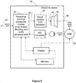
- Figure 5 shows an illustrative example among many others of a block diagram of an electronic device 30 comprising a loudspeaker 36 with a sound sponge block, according to an embodiment of the present invention.
- the electronic device 30 can be (but is not limited to), e.g., a communication device, a wireless communication device, a portable electronic device, a mobile electronic device, a mobile phone, a computer, etc.
- a receiving/sending/processing module 32 (which can include, besides receiver, transmitter, CPU, etc., also decoding and audio enhancement means) receives or sends a speech signal 40.
- the block 32 When the speech signal 40 is received, the block 32 generates the received signal 42 which is further provided to the user 38 as an audio speech signal (i.e., an electric drive signal) 46 using a signal provider (digital-to-analog (D/A) converter) 34 and a speaker 36.
- the electronic device 30 comprises other standard blocks such as display, memory and a microphone for providing an electronic signal in response to an acoustic signal generated by the user 38 (the electronic signal is further provided to the block 32 for sending the speech signal 40 to the outside addressee).
- the loudspeaker 36 can be implemented as a separate block, or it can be combined with any other standard block of the electronic device 30.
- the loudspeaker 36 can be combined, as discussed above, with the display of the electronic device 30, if the loudspeaker 36 is implemented in the transparent version, e.g., with transparent diaphragm 14a and electrodes 22a and 22b in the electrostatic implementation as shown in Figure 2b . Then the loudspeaker 36 could be mounted directly in front of a display.
Landscapes
- Health & Medical Sciences (AREA)
- Otolaryngology (AREA)
- Physics & Mathematics (AREA)
- Engineering & Computer Science (AREA)
- Acoustics & Sound (AREA)
- Signal Processing (AREA)
- Audible-Bandwidth Dynamoelectric Transducers Other Than Pickups (AREA)
- Details Of Audible-Bandwidth Transducers (AREA)
- Diaphragms For Electromechanical Transducers (AREA)
Claims (14)
- Lautsprechersystem (10a, 20a), umfassend:eine Membran (16), die konfiguriert ist, um ein akustisches Signal durch Vibrationen aus dem Lautsprechersystem in Vorwärts- und Rückwärtsrichtung bereitzustellen; undein akustischer Absorber (18), eine Anordnung von mehreren Kanälen (16) umfassend, wobei die Kanäle aus einem vorgewählten Material mit vorbestimmten geometrischen Abmessungen bestehen, die parallel zueinander angeordnet sind, der hinter der Membran angeordnet ist, sodass die mehreren Kanäle im Wesentlichen senkrecht zu einer Oberfläche der Membran angeordnet sind, ohne die Membran physisch zu berühren, wobei die Enden der mehreren Kanäle, die am weitesten von der Membran entfernt sind, abgedichtet sind und eine unendliche spezifische Abschlussimpedanz aufweisen, und der akustische Absorber (18) konfiguriert ist, um Schallwellen im Wesentlichen zu absorbieren, die von einer Rückseite der Membran in einer Rückwärtsrichtung abgestrahlt werden.
- Lautsprechersystem nach Anspruch 1, wobei die mehreren Kanäle runde Zylinder sind.
- Lautsprechersystem nach Anspruch 2, wobei die runden Zylinder einen Durchmesser zwischen 0,1 und 10 Mikrometer aufweisen.
- Lautsprechersystem nach Anspruch 1, wobei ein Querschnitt der mehreren Kanäle 90 % oder weniger einer Gesamtquerschnittsfläche des akustischen Absorbers umfasst.
- Lautsprechersystem nach Anspruch 1, wobei der akustische Absorber einen Realteil einer akustischen Impedanz aufweist, die im Wesentlichen konstant in einem vorbestimmten Frequenzbereich ist.
- Lautsprechersystem nach Anspruch 5, wobei der Frequenzbereich zwischen 10 Hz bis 10.000 Hz liegt.
- Elektronisches Gerät (30), umfassend:eine Signalbereitstellungseinrichtung (34), die konfiguriert ist, um ein elektrisches Treibersignal bereitzustellen; undLautsprechersystem (36) nach einem der Ansprüche 1 bis 6, auf das elektrische Treibersignal ansprechend, das konfiguriert ist, um ein akustisches Signal des elektronischen Geräts in Reaktion auf das elektrische Treibersignal bereitzustellen.
- Elektronisches Gerät nach Anspruch 7, wobei die Membran aus optisch transparentem Material hergestellt ist, sodass das Lautsprechersystem mit einer Anzeigevorrichtung des elektronischen Geräts kombiniert ist, um der Anzeigevorrichtung vorgeschaltet zu werden, und/oderdas elektronische Gerät ein Kommunikationsgerät, ein Computer, ein drahtloses Kommunikationsgerät, ein tragbares elektronisches Gerät, ein mobiles elektronisches Gerät oder ein Mobiltelefon ist.
- Verfahren, umfassend:Bereitstellen eines akustischen Signals in Vorwärts- und Rückwärtsrichtungen durch Vibrationen einer Membran eines Lautsprechersystems; undAbsorption der Schallwellen, die von einer Rückseite der Membran in Rückwärtsrichtung abgestrahlt werden, unter Verwendung eines akustischen Absorbers (18), der eine Anordnung von mehreren Kanälen (16) umfasst, wobei die mehreren Kanäle aus einem vorgewählten Material mit vorbestimmten geometrischen Abmessungen bestehen, die parallel zueinander angeordnet sind, wobei die Enden der mehreren Kanäle, die am weitesten von der Membran entfernt sind, abgedichtet sind und eine unendliche spezifische Abschlussimpedanz aufweisen, wobei der akustische Absorber hinter der Membran angeordnet ist, sodass die mehreren Kanäle im Wesentlichen senkrecht zu einer Oberfläche der Membran angeordnet sind, ohne die Membran physisch zu berühren, wobei der akustische Absorber konfiguriert ist, um die Schallwellen im Wesentlichen zu absorbieren.
- Verfahren nach Anspruch 9, wobei die mehreren Kanäle runde Zylinder sind.
- Verfahren nach Anspruch 10, wobei die runden Zylinder einen Durchmesser zwischen 0,1 und 10 Mikrometer aufweisen.
- Verfahren nach Anspruch 9, wobei ein Querschnitt der mehreren Kanäle 90 % oder weniger einer Gesamtquerschnittsfläche des akustischen Absorbers umfasst.
- Verfahren nach Anspruch 9, wobei der akustische Absorber einen Realteil einer akustischen Impedanz aufweist, die im Wesentlichen konstant in einem vorbestimmten Frequenzbereich ist.
- Verfahren nach Anspruch 13, wobei der Frequenzbereich zwischen 10 Hz bis 10.000 Hz liegt.
Applications Claiming Priority (2)
| Application Number | Priority Date | Filing Date | Title |
|---|---|---|---|
| US11/373,825 US7801320B2 (en) | 2006-03-09 | 2006-03-09 | Sound sponge for loudspeakers |
| PCT/IB2007/000361 WO2007102056A1 (en) | 2006-03-09 | 2007-02-15 | Sound sponge for loudspeakers |
Publications (3)
| Publication Number | Publication Date |
|---|---|
| EP1992192A1 EP1992192A1 (de) | 2008-11-19 |
| EP1992192A4 EP1992192A4 (de) | 2010-06-02 |
| EP1992192B1 true EP1992192B1 (de) | 2016-12-28 |
Family
ID=38474631
Family Applications (1)
| Application Number | Title | Priority Date | Filing Date |
|---|---|---|---|
| EP07705595.2A Active EP1992192B1 (de) | 2006-03-09 | 2007-02-15 | Schallschwamm für lautsprecher |
Country Status (4)
| Country | Link |
|---|---|
| US (1) | US7801320B2 (de) |
| EP (1) | EP1992192B1 (de) |
| CN (1) | CN101395956B (de) |
| WO (1) | WO2007102056A1 (de) |
Families Citing this family (5)
| Publication number | Priority date | Publication date | Assignee | Title |
|---|---|---|---|---|
| US8630435B2 (en) * | 2008-08-08 | 2014-01-14 | Nokia Corporation | Apparatus incorporating an adsorbent material, and methods of making same |
| US9516406B2 (en) * | 2011-12-20 | 2016-12-06 | Nokia Technologies Oy | Portable device with enhanced bass response |
| JP2014165862A (ja) * | 2013-02-27 | 2014-09-08 | Yamaha Corp | スピーカ |
| US10575098B2 (en) * | 2018-02-13 | 2020-02-25 | Nokia Technologies Oy | Speaker apparatus having a heat dissipation structure |
| US10841706B2 (en) | 2018-02-13 | 2020-11-17 | Nokia Technologies Oy | Speaker apparatus having a heat dissipation structure including an active element |
Family Cites Families (12)
| Publication number | Priority date | Publication date | Assignee | Title |
|---|---|---|---|---|
| US2228886A (en) * | 1938-10-31 | 1941-01-14 | Rca Corp | Electroacoustical apparatus |
| US2225312A (en) * | 1939-10-05 | 1940-12-17 | Bell Telephone Labor Inc | Acoustic device |
| US2262146A (en) * | 1940-01-31 | 1941-11-11 | Rca Corp | Sound translating apparatus |
| GB626623A (en) | 1945-09-15 | 1949-07-19 | Murphy Radio Ltd | Improvements in and relating to loud speakers |
| US3936606A (en) * | 1971-12-07 | 1976-02-03 | Wanke Ronald L | Acoustic abatement method and apparatus |
| US4493389A (en) * | 1982-05-27 | 1985-01-15 | Luis Del Rosario | Speaker assembly |
| DE69431177T2 (de) * | 1993-09-22 | 2003-05-08 | Sony Corp., Tokio/Tokyo | Hornlautsprecher-System |
| EP1012891A2 (de) | 1997-09-05 | 2000-06-28 | 1... Ipr Limited | Aerogele, piezoelektrische anordnungen, und ihre verwendung |
| DE19859046A1 (de) | 1998-12-21 | 2000-07-20 | Norbert Schaefer | Tiefton-Membranlautsprecher |
| CA2396260C (en) * | 2000-01-07 | 2007-09-11 | Lewis Athanas | Mechanical-to-acoustical transformer and multi-media flat film speaker |
| US7072481B2 (en) * | 2000-07-31 | 2006-07-04 | Harman International Industries, Inc. | Two-stage phasing plug system in a compression driver |
| JP4338470B2 (ja) | 2003-08-12 | 2009-10-07 | 日鉄鉱業株式会社 | ハイドロタルサイト粒子及びその製造方法 |
-
2006
- 2006-03-09 US US11/373,825 patent/US7801320B2/en active Active
-
2007
- 2007-02-15 EP EP07705595.2A patent/EP1992192B1/de active Active
- 2007-02-15 CN CN200780008154.3A patent/CN101395956B/zh active Active
- 2007-02-15 WO PCT/IB2007/000361 patent/WO2007102056A1/en not_active Ceased
Non-Patent Citations (1)
| Title |
|---|
| None * |
Also Published As
| Publication number | Publication date |
|---|---|
| EP1992192A4 (de) | 2010-06-02 |
| CN101395956A (zh) | 2009-03-25 |
| WO2007102056A1 (en) | 2007-09-13 |
| US7801320B2 (en) | 2010-09-21 |
| US20070223776A1 (en) | 2007-09-27 |
| CN101395956B (zh) | 2014-02-26 |
| EP1992192A1 (de) | 2008-11-19 |
Similar Documents
| Publication | Publication Date | Title |
|---|---|---|
| Wang et al. | Ultrathin and durable open metamaterials for simultaneous ventilation and sound reduction | |
| CN113596672B (zh) | 扬声器模组及电子设备 | |
| Lu et al. | An electronically tunable duct silencer using dielectric elastomer actuators | |
| AU754818B2 (en) | Resonant panel-form loudspeaker | |
| SK14932000A3 (sk) | Akustické zariadenie | |
| US6304662B1 (en) | Sonic emitter with foam stator | |
| CN204377095U (zh) | 偶极高辐射抗型耳机 | |
| EP1398992A1 (de) | Rechteckiger plattenförmiger Lautsprecher und Abstrahlplatte desselben | |
| Chiang et al. | Vibration and sound radiation of an electrostatic speaker based on circular diaphragm | |
| Bai et al. | Development of panel loudspeaker system: Design, evaluation and enhancement | |
| KR20250079140A (ko) | 저 공진 구조 및 전기 디바이스 | |
| EP1992192A1 (de) | Schallschwamm für lautsprecher | |
| Langfeldt et al. | Controlling the effective surface mass density of membrane-type acoustic metamaterials using dynamic actuators | |
| CN109348380B (zh) | 发声装置及便携终端 | |
| CN102959992B (zh) | 振荡器和电子设备 | |
| CN104335598A (zh) | 扬声器设备和电子设备 | |
| CN1140158C (zh) | 包含相位不相关扩散声源的扬声器 | |
| JP2005500725A (ja) | ラウドスピーカ及びタッチパッドを備える電子物品 | |
| JP7523519B2 (ja) | スピーカ及び電子機器 | |
| Chiang et al. | Experimental modeling and application of push-pull electrostatic speakers | |
| CN218103499U (zh) | 低共振结构及电子设备 | |
| WO2007054878A1 (en) | Arrangement for optimizing the frequency response of an electro-acoustic transducer | |
| Kim et al. | Zero Poisson's ratio metamaterial and meander-inspired diaphragms for enhancing low-frequency performance in flat-panel loudspeaker | |
| CN117896660A (zh) | 扬声器模组及终端设备 | |
| CN114783400A (zh) | 一种并联弹簧振子吸声结构 |
Legal Events
| Date | Code | Title | Description |
|---|---|---|---|
| PUAI | Public reference made under article 153(3) epc to a published international application that has entered the european phase |
Free format text: ORIGINAL CODE: 0009012 |
|
| 17P | Request for examination filed |
Effective date: 20080820 |
|
| AK | Designated contracting states |
Kind code of ref document: A1 Designated state(s): AT BE BG CH CY CZ DE DK EE ES FI FR GB GR HU IE IS IT LI LT LU LV MC NL PL PT RO SE SI SK TR |
|
| A4 | Supplementary search report drawn up and despatched |
Effective date: 20100507 |
|
| DAX | Request for extension of the european patent (deleted) | ||
| 17Q | First examination report despatched |
Effective date: 20140131 |
|
| RAP1 | Party data changed (applicant data changed or rights of an application transferred) |
Owner name: NOKIA CORPORATION |
|
| RAP1 | Party data changed (applicant data changed or rights of an application transferred) |
Owner name: NOKIA TECHNOLOGIES OY |
|
| GRAP | Despatch of communication of intention to grant a patent |
Free format text: ORIGINAL CODE: EPIDOSNIGR1 |
|
| INTG | Intention to grant announced |
Effective date: 20160715 |
|
| GRAS | Grant fee paid |
Free format text: ORIGINAL CODE: EPIDOSNIGR3 |
|
| GRAA | (expected) grant |
Free format text: ORIGINAL CODE: 0009210 |
|
| AK | Designated contracting states |
Kind code of ref document: B1 Designated state(s): AT BE BG CH CY CZ DE DK EE ES FI FR GB GR HU IE IS IT LI LT LU LV MC NL PL PT RO SE SI SK TR |
|
| REG | Reference to a national code |
Ref country code: GB Ref legal event code: FG4D |
|
| REG | Reference to a national code |
Ref country code: CH Ref legal event code: EP |
|
| REG | Reference to a national code |
Ref country code: AT Ref legal event code: REF Ref document number: 858188 Country of ref document: AT Kind code of ref document: T Effective date: 20170115 |
|
| REG | Reference to a national code |
Ref country code: IE Ref legal event code: FG4D |
|
| REG | Reference to a national code |
Ref country code: DE Ref legal event code: R096 Ref document number: 602007049304 Country of ref document: DE |
|
| PG25 | Lapsed in a contracting state [announced via postgrant information from national office to epo] |
Ref country code: LV Free format text: LAPSE BECAUSE OF FAILURE TO SUBMIT A TRANSLATION OF THE DESCRIPTION OR TO PAY THE FEE WITHIN THE PRESCRIBED TIME-LIMIT Effective date: 20161228 |
|
| REG | Reference to a national code |
Ref country code: NL Ref legal event code: FP |
|
| REG | Reference to a national code |
Ref country code: LT Ref legal event code: MG4D |
|
| PG25 | Lapsed in a contracting state [announced via postgrant information from national office to epo] |
Ref country code: SE Free format text: LAPSE BECAUSE OF FAILURE TO SUBMIT A TRANSLATION OF THE DESCRIPTION OR TO PAY THE FEE WITHIN THE PRESCRIBED TIME-LIMIT Effective date: 20161228 Ref country code: GR Free format text: LAPSE BECAUSE OF FAILURE TO SUBMIT A TRANSLATION OF THE DESCRIPTION OR TO PAY THE FEE WITHIN THE PRESCRIBED TIME-LIMIT Effective date: 20170329 Ref country code: LT Free format text: LAPSE BECAUSE OF FAILURE TO SUBMIT A TRANSLATION OF THE DESCRIPTION OR TO PAY THE FEE WITHIN THE PRESCRIBED TIME-LIMIT Effective date: 20161228 |
|
| REG | Reference to a national code |
Ref country code: AT Ref legal event code: MK05 Ref document number: 858188 Country of ref document: AT Kind code of ref document: T Effective date: 20161228 |
|
| PG25 | Lapsed in a contracting state [announced via postgrant information from national office to epo] |
Ref country code: FI Free format text: LAPSE BECAUSE OF FAILURE TO SUBMIT A TRANSLATION OF THE DESCRIPTION OR TO PAY THE FEE WITHIN THE PRESCRIBED TIME-LIMIT Effective date: 20161228 Ref country code: BE Free format text: LAPSE BECAUSE OF NON-PAYMENT OF DUE FEES Effective date: 20170228 |
|
| PG25 | Lapsed in a contracting state [announced via postgrant information from national office to epo] |
Ref country code: IS Free format text: LAPSE BECAUSE OF FAILURE TO SUBMIT A TRANSLATION OF THE DESCRIPTION OR TO PAY THE FEE WITHIN THE PRESCRIBED TIME-LIMIT Effective date: 20170428 Ref country code: EE Free format text: LAPSE BECAUSE OF FAILURE TO SUBMIT A TRANSLATION OF THE DESCRIPTION OR TO PAY THE FEE WITHIN THE PRESCRIBED TIME-LIMIT Effective date: 20161228 Ref country code: SK Free format text: LAPSE BECAUSE OF FAILURE TO SUBMIT A TRANSLATION OF THE DESCRIPTION OR TO PAY THE FEE WITHIN THE PRESCRIBED TIME-LIMIT Effective date: 20161228 Ref country code: RO Free format text: LAPSE BECAUSE OF FAILURE TO SUBMIT A TRANSLATION OF THE DESCRIPTION OR TO PAY THE FEE WITHIN THE PRESCRIBED TIME-LIMIT Effective date: 20161228 Ref country code: CZ Free format text: LAPSE BECAUSE OF FAILURE TO SUBMIT A TRANSLATION OF THE DESCRIPTION OR TO PAY THE FEE WITHIN THE PRESCRIBED TIME-LIMIT Effective date: 20161228 |
|
| PG25 | Lapsed in a contracting state [announced via postgrant information from national office to epo] |
Ref country code: PT Free format text: LAPSE BECAUSE OF FAILURE TO SUBMIT A TRANSLATION OF THE DESCRIPTION OR TO PAY THE FEE WITHIN THE PRESCRIBED TIME-LIMIT Effective date: 20170428 Ref country code: BE Free format text: LAPSE BECAUSE OF FAILURE TO SUBMIT A TRANSLATION OF THE DESCRIPTION OR TO PAY THE FEE WITHIN THE PRESCRIBED TIME-LIMIT Effective date: 20161228 Ref country code: ES Free format text: LAPSE BECAUSE OF FAILURE TO SUBMIT A TRANSLATION OF THE DESCRIPTION OR TO PAY THE FEE WITHIN THE PRESCRIBED TIME-LIMIT Effective date: 20161228 Ref country code: PL Free format text: LAPSE BECAUSE OF FAILURE TO SUBMIT A TRANSLATION OF THE DESCRIPTION OR TO PAY THE FEE WITHIN THE PRESCRIBED TIME-LIMIT Effective date: 20161228 Ref country code: IT Free format text: LAPSE BECAUSE OF FAILURE TO SUBMIT A TRANSLATION OF THE DESCRIPTION OR TO PAY THE FEE WITHIN THE PRESCRIBED TIME-LIMIT Effective date: 20161228 Ref country code: AT Free format text: LAPSE BECAUSE OF FAILURE TO SUBMIT A TRANSLATION OF THE DESCRIPTION OR TO PAY THE FEE WITHIN THE PRESCRIBED TIME-LIMIT Effective date: 20161228 Ref country code: BG Free format text: LAPSE BECAUSE OF FAILURE TO SUBMIT A TRANSLATION OF THE DESCRIPTION OR TO PAY THE FEE WITHIN THE PRESCRIBED TIME-LIMIT Effective date: 20170328 |
|
| PG25 | Lapsed in a contracting state [announced via postgrant information from national office to epo] |
Ref country code: MC Free format text: LAPSE BECAUSE OF FAILURE TO SUBMIT A TRANSLATION OF THE DESCRIPTION OR TO PAY THE FEE WITHIN THE PRESCRIBED TIME-LIMIT Effective date: 20161228 |
|
| REG | Reference to a national code |
Ref country code: CH Ref legal event code: PL Ref country code: DE Ref legal event code: R097 Ref document number: 602007049304 Country of ref document: DE |
|
| PG25 | Lapsed in a contracting state [announced via postgrant information from national office to epo] |
Ref country code: LI Free format text: LAPSE BECAUSE OF NON-PAYMENT OF DUE FEES Effective date: 20170228 Ref country code: CH Free format text: LAPSE BECAUSE OF NON-PAYMENT OF DUE FEES Effective date: 20170228 |
|
| PLBE | No opposition filed within time limit |
Free format text: ORIGINAL CODE: 0009261 |
|
| STAA | Information on the status of an ep patent application or granted ep patent |
Free format text: STATUS: NO OPPOSITION FILED WITHIN TIME LIMIT |
|
| REG | Reference to a national code |
Ref country code: IE Ref legal event code: MM4A |
|
| PG25 | Lapsed in a contracting state [announced via postgrant information from national office to epo] |
Ref country code: DK Free format text: LAPSE BECAUSE OF FAILURE TO SUBMIT A TRANSLATION OF THE DESCRIPTION OR TO PAY THE FEE WITHIN THE PRESCRIBED TIME-LIMIT Effective date: 20161228 |
|
| REG | Reference to a national code |
Ref country code: FR Ref legal event code: ST Effective date: 20171031 |
|
| 26N | No opposition filed |
Effective date: 20170929 |
|
| PG25 | Lapsed in a contracting state [announced via postgrant information from national office to epo] |
Ref country code: LU Free format text: LAPSE BECAUSE OF NON-PAYMENT OF DUE FEES Effective date: 20170215 |
|
| PG25 | Lapsed in a contracting state [announced via postgrant information from national office to epo] |
Ref country code: FR Free format text: LAPSE BECAUSE OF NON-PAYMENT OF DUE FEES Effective date: 20170228 |
|
| PG25 | Lapsed in a contracting state [announced via postgrant information from national office to epo] |
Ref country code: SI Free format text: LAPSE BECAUSE OF FAILURE TO SUBMIT A TRANSLATION OF THE DESCRIPTION OR TO PAY THE FEE WITHIN THE PRESCRIBED TIME-LIMIT Effective date: 20161228 Ref country code: IE Free format text: LAPSE BECAUSE OF NON-PAYMENT OF DUE FEES Effective date: 20170215 |
|
| PG25 | Lapsed in a contracting state [announced via postgrant information from national office to epo] |
Ref country code: HU Free format text: LAPSE BECAUSE OF FAILURE TO SUBMIT A TRANSLATION OF THE DESCRIPTION OR TO PAY THE FEE WITHIN THE PRESCRIBED TIME-LIMIT; INVALID AB INITIO Effective date: 20070215 |
|
| PG25 | Lapsed in a contracting state [announced via postgrant information from national office to epo] |
Ref country code: CY Free format text: LAPSE BECAUSE OF NON-PAYMENT OF DUE FEES Effective date: 20161228 |
|
| PG25 | Lapsed in a contracting state [announced via postgrant information from national office to epo] |
Ref country code: TR Free format text: LAPSE BECAUSE OF FAILURE TO SUBMIT A TRANSLATION OF THE DESCRIPTION OR TO PAY THE FEE WITHIN THE PRESCRIBED TIME-LIMIT Effective date: 20161228 |
|
| P01 | Opt-out of the competence of the unified patent court (upc) registered |
Effective date: 20230527 |
|
| PGFP | Annual fee paid to national office [announced via postgrant information from national office to epo] |
Ref country code: NL Payment date: 20260106 Year of fee payment: 20 |
|
| PGFP | Annual fee paid to national office [announced via postgrant information from national office to epo] |
Ref country code: GB Payment date: 20260106 Year of fee payment: 20 |
|
| PGFP | Annual fee paid to national office [announced via postgrant information from national office to epo] |
Ref country code: DE Payment date: 20251230 Year of fee payment: 20 |