EP1991999B1 - Electrical switching device - Google Patents
Electrical switching device Download PDFInfo
- Publication number
- EP1991999B1 EP1991999B1 EP20070704621 EP07704621A EP1991999B1 EP 1991999 B1 EP1991999 B1 EP 1991999B1 EP 20070704621 EP20070704621 EP 20070704621 EP 07704621 A EP07704621 A EP 07704621A EP 1991999 B1 EP1991999 B1 EP 1991999B1
- Authority
- EP
- European Patent Office
- Prior art keywords
- interrupter unit
- air
- switch
- grounding switch
- interrupter
- Prior art date
- Legal status (The legal status is an assumption and is not a legal conclusion. Google has not performed a legal analysis and makes no representation as to the accuracy of the status listed.)
- Expired - Fee Related
Links
Images

Classifications
-
- H—ELECTRICITY
- H01—ELECTRIC ELEMENTS
- H01H—ELECTRIC SWITCHES; RELAYS; SELECTORS; EMERGENCY PROTECTIVE DEVICES
- H01H33/00—High-tension or heavy-current switches with arc-extinguishing or arc-preventing means
- H01H33/02—Details
- H01H33/04—Means for extinguishing or preventing arc between current-carrying parts
- H01H33/12—Auxiliary contacts on to which the arc is transferred from the main contacts
- H01H33/121—Load break switches
- H01H33/125—Load break switches comprising a separate circuit breaker
- H01H33/126—Load break switches comprising a separate circuit breaker being operated by the distal end of a sectionalising contact arm
-
- H—ELECTRICITY
- H01—ELECTRIC ELEMENTS
- H01H—ELECTRIC SWITCHES; RELAYS; SELECTORS; EMERGENCY PROTECTIVE DEVICES
- H01H31/00—Air-break switches for high tension without arc-extinguishing or arc-preventing means
- H01H31/003—Earthing switches
-
- H—ELECTRICITY
- H01—ELECTRIC ELEMENTS
- H01H—ELECTRIC SWITCHES; RELAYS; SELECTORS; EMERGENCY PROTECTIVE DEVICES
- H01H33/00—High-tension or heavy-current switches with arc-extinguishing or arc-preventing means
- H01H33/60—Switches wherein the means for extinguishing or preventing the arc do not include separate means for obtaining or increasing flow of arc-extinguishing fluid
- H01H33/66—Vacuum switches
- H01H33/666—Operating arrangements
- H01H33/6661—Combination with other type of switch, e.g. for load break switches
Definitions
- the invention relates to an electrical switching device with a first interrupter unit for interrupting and connecting an electrical line, in particular an air-insulated earthing switch, wherein in the electrical switching device at least a second encapsulated interrupter unit is arranged parallel to the first interrupter unit and the voltage flashovers arising when connecting or disconnecting the electrical line Arcs occur in the second interrupter unit, wherein the second interrupter unit when connecting the electrical line before the first interrupter unit and when interrupting the electrical line after the first interrupter unit is switchable. Furthermore, the invention relates to a method for switching an air-insulated earthing switch, wherein at the air-insulated earthing switch no arc due to a voltage flashover or the contact separation is formed.
- Conventional air-insulated earthing switches are designed as a swivel or as a swing-thruster earth electrode. When connecting a line or a switchgear to the ground potential or switching off the earth potential, these switch-on processes generate a capacitive and / or an inductive current, which can lead to an arc at a certain distance between the main contacts of the earthing switch. Since the earthing switches are usually operated in open-air systems, this open arc poses a risk to the persons and electrical devices in the system. To date, this problem has been solved by switching an auxiliary contact with a leading or lagging function to the main contact. Only at the auxiliary contact ignites an emerging arc. As a result, the main contacts of the air-insulated earthing switch are protected from the action of arcing. The disadvantage here is that the case Arcing continues to develop outdoors and thus poses a safety risk.
- An electrical switching device of the type mentioned is from the US 5,276,286 known.
- the object of the present invention is to ensure arc-free switching of a main switch.
- the object is achieved in that a circuit breaker between the air-insulated earthing switch and the second interrupter unit is arranged and by means of a receiving device on a movable main contact of the air-insulated earthing switch befind Anlagen first part of the circuit breaker makes contact with the second part of the circuit breaker.
- the inventive switchgear ensures that a possible arc occurs exclusively in the second interrupter unit and thus the first interrupter unit can be switched in an arc-free manner.
- this results in the advantage that a possible arc does not occur at the main contacts of the air-insulated earthing switch and thus extends the life of the switchgear.
- the receiving device By the movement of the movable main contact by means of the first part of the circuit breaker, the receiving device performs a rotational movement. Shortly before reaching the end position for the switched state of the main movable contact performs a lifting movement in the fixed main contact. This movement sequence of the movable main contact is used to interrupt the existing electrical connection between the two parts of the circuit breaker again in the on state. Previously, the vacuum switching chamber has been switched by the rotation and lifting movement. In the end position of the movable main contact in the switched state, the second interrupter unit is therefore again electrically separated from the main flow path by the opened disconnect switch.
- the first part of the circuit breaker is dimensioned so that with a sufficient separation distance between the main contacts, the receiving device due to the rotational movement then the second interrupter unit, such as a vacuum interrupter opens. A resulting arc remains in the chamber of the second interrupter unit.
- the circuit breaker can also be opened without power. This movement is ensured by the coordinated geometry and design of the movable main contact, the length and arrangement of the first part of the circuit breaker, as well as the design of the receiving device.
- the second interrupter unit is a circuit breaker and / or a load switch and / or a disconnector and / or a vacuum interrupter chamber and / or a surge arrester, e.g. a spark gap and / or a voltage limiter.
- the arc is ignited exclusively in the closed chamber of the second interrupter unit and thus shielded to the outside.
- a serial arrangement of the two sub-cup units can be used.
- the second interrupter unit is arranged on the voltage potential side, in particular the high-voltage potential side, which is applied to the switching device.
- at least one further interrupter unit for discharging overvoltages is arranged in parallel and / or in series with the second interrupter unit.
- the third interrupter unit is a surge arrester, a spark gap, open or encapsulated or other voltage limiters.
- the rated voltage of the second interrupter unit can be selected smaller than the rated voltage of the first switching chamber.
- the second interrupter unit is integrated in a fixed contact of an air-insulated earthing switch as the first interrupter unit. This results in the advantage that existing earthing switchgear can be retrofitted with a corresponding second interrupter unit.
- the second interrupter unit is connected in parallel or in series with the first interrupter unit.
- the current strengths of the two interrupter units must be designed in each case with respect to the maximum currents.
- the current stability of the second interrupter unit can be dimensioned smaller than the first interrupter unit. In this case, the use of a circuit breaker between the first and second interrupter unit is then advantageous.
- a method of switching an air-insulated earthing switch the air-insulated earthing switch being connected to a second interrupter unit arranged parallel to the air-insulated earthing switch, the second interrupter unit closing the electrical line before the air-insulated earthing switch and first disconnecting the electric wire air-insulated earthing switch and only then the second interrupter unit is disconnected from the electrical line, wherein a contact to the second part of a circuit breaker is made by a receiving device located at a movable main contact of the air-insulated earthing switch first part of a circuit breaker.
- the disconnection point When using a separation point as the connection between the air-insulated earthing switch and the second interrupter unit, the disconnection point is first closed, then the second interrupter unit, then the air-insulated earthing switch and opened the disconnection point when the line connection is established.
- the open separation point When switching off the open separation point is first closed, then open the air-insulated earthing switch, then opened the second interrupter unit under any occurring generation of an arc and opened the separation point again after complete separation of the electrical line.
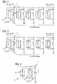
- FIG. 1 shows a schematic side view of an air-insulated earthing switch 2 as a first interrupter unit as part of an electrical switching device (not shown).
- a vacuum interrupter chamber 3 is integrated as a second interrupter unit.
- a boom 5a on the movable main contact 4b engages during the rotational movement of the movable main contact 4b during the switch-on in the receiving device 6 and thus establishes an electrical connection via the separation point 5a, 5b ago.
- the vacuum interrupter chamber 3 is then also closed.
- a resulting arc can be deleted within the vacuum interrupter chamber 3.
- the disconnection point 5a, 5b is opened again by means of the extension of FIG. 5a, so that the main flow path exclusively through the air-insulated earthing switch 2 runs.
- the separation point 5a, 5b separates the vacuum interrupter chamber 3 from the ground current path.
- the separation point 5a, 5b is opened by extending the main movable contact 4b, so that now the vacuum interrupter chamber 3 and the air-insulated earthing switch 2 are completely disconnected and de-energized.
- the figure Fig. 2 shows a method sequence according to the invention for the arc-free switching on an air-insulated grounding switch 2 using an additional separation point 5a, 5b.
- the air-insulated earthing switch 2 and the second interrupter unit 3 as a vacuum switch and a separating point 5a, 5b arranged between the air-insulated earthing switch 2 and the vacuum interrupter 3 are opened.
- the separation point 5a, 5b is now closed first and then made an electrical connection of the line 7 via the vacuum interrupter chamber 3.
- An optionally resulting arc is deleted within the vacuum interrupter chamber 3.
- the fixed main contact 4 a of the air-insulated grounding switch 2 is closed, in which case now no arc can occur.
- the vacuum interrupter chamber 3 is subsequently separated from the electrical line 7 by means of the separation point 5a, 5b.
- FIG. 3 shows a turn-off operation according to the invention of arc-free switching of an air-insulated earthing switch 2 in conjunction with a vacuum interrupter chamber 3 as a second interrupter unit and a separation point 5a, 5b.
- the movable main contact 4b of the air-oiled grounding switch 2 is subsequently removed from the fixed main contact 4a.
- the electrical connection is made in this phase exclusively via the vacuum interrupter chamber 3 as a second interrupter unit.
- the contacts of the vacuum interrupter chamber 3 are also opened, so that an optionally resulting arc exclusively in the vacuum interrupter chamber 3 ignites.
- the fixed main contact 4a of the air-insulated grounding switch 2 is now far enough away from the main movable contact 4b to ignite an arc in the air between the main contacts 4a, 4b due to the separation distance.
- the separation point 5a, 5b is opened, so that the electrical connection is now canceled.
- the kinematics in the main flow path is used to make the appropriate switching operation.
- the movement of the movable main contact 4b is used for the force to be used for closing or opening the separation point 5a, 5b and the vacuum interrupter chamber 3 as a second interrupter unit.
- the vacuum interrupter chamber 3 does not need its own power supply and it is also no auxiliary flow path parallel to the earth current necessary.
- the figure Fig. 4 shows a circuit diagram of the switchgear 1 according to the invention with a arranged parallel to the second interrupter unit 3 surge arrester as a third interrupter unit 8.
- the parallel to the earthing switch 2 arranged as a first interrupter vacuum interrupter chamber 3 as the second interrupter unit is additionally protected by the third interrupter unit 8 as a spark gap and limited in voltage ,
- the vacuum chamber 3 can be dimensioned smaller than the earthing switch 2 with respect to the voltage and current resistance.
- further interrupter units may additionally be arranged in parallel and / or in series with respect to the vacuum interrupter chamber 3 in the electrical switchgear 1.
Abstract
Description
Die Erfindung betrifft ein elektrisches Schaltgerät mit einer ersten Unterbrechereinheit zum Unterbrechen und Verbinden einer elektrischen Leitung, insbesondere ein luftisolierter Erdungsschalter, wobei im elektrischen Schaltgerät mindestens eine zweite gekapselte Unterbrechereinheit parallel zur ersten Unterbrechereinheit angeordnet ist und die beim Verbinden oder Unterbrechen der elektrischen Leitung entstehenden Spannungsüberschläge als Lichtbögen in der zweiten Unterbrechereinheit auftreten, wobei die zweite Unterbrechereinheit beim Verbinden der elektrischen Leitung vor der ersten Unterbrechereinheit und beim Unterbrechen der elektrischen Leitung nach der ersten Unterbrechereinheit schaltbar ist. Weiterhin betrifft die Erfindung ein Verfahren zum Schalten eines luftisolierten Erdungsschalters, wobei am luftisolierten Erdungsschalter kein Lichtbogen aufgrund eines Spannungsüberschlages bzw. der Kontakttrennung entsteht.The invention relates to an electrical switching device with a first interrupter unit for interrupting and connecting an electrical line, in particular an air-insulated earthing switch, wherein in the electrical switching device at least a second encapsulated interrupter unit is arranged parallel to the first interrupter unit and the voltage flashovers arising when connecting or disconnecting the electrical line Arcs occur in the second interrupter unit, wherein the second interrupter unit when connecting the electrical line before the first interrupter unit and when interrupting the electrical line after the first interrupter unit is switchable. Furthermore, the invention relates to a method for switching an air-insulated earthing switch, wherein at the air-insulated earthing switch no arc due to a voltage flashover or the contact separation is formed.
Herkömmliche luftisolierte Erdungsschalter sind als Schwenkoder als Schwenk-Schub-Erder ausgestaltet. Beim Aufschalten einer Leitung oder einer Schaltanlage auf das Erdpotenzial bzw. Abschalten vom Erdpotenzial erzeugen diese Einschaltvorgänge einen kapazitiven und/oder einen induktiven Strom, der bei einem bestimmten Abstand der Hauptkontakte des Erdungsschalters zueinander zu einem Lichtbogen führen kann. Da die Erdungsschalter zumeist in Freiluftanlagen betrieben werden, stellt dieser offene Lichtbogen eine Gefahr für die in der Anlage befindlichen Personen und elektrischen Geräte dar. Bisher wurde dieses Problem dadurch gelöst, dass ein Hilfskontakt mit voraus- beziehungsweise nacheilender Funktion zum Hauptkontakt geschaltet wird. Ausschließlich am Hilfskontakt zündet ein entstehender Lichtbogen. Hierdurch sind die Hauptkontakte des luftisolierten Erdungsschalters vor der Lichtbogeneinwirkung geschützt. Nachteilig hierbei ist, dass der dabei entstehende Lichtbogen weiterhin im Freien entsteht und damit ein Sicherheitsrisiko darstellt.Conventional air-insulated earthing switches are designed as a swivel or as a swing-thruster earth electrode. When connecting a line or a switchgear to the ground potential or switching off the earth potential, these switch-on processes generate a capacitive and / or an inductive current, which can lead to an arc at a certain distance between the main contacts of the earthing switch. Since the earthing switches are usually operated in open-air systems, this open arc poses a risk to the persons and electrical devices in the system. To date, this problem has been solved by switching an auxiliary contact with a leading or lagging function to the main contact. Only at the auxiliary contact ignites an emerging arc. As a result, the main contacts of the air-insulated earthing switch are protected from the action of arcing. The disadvantage here is that the case Arcing continues to develop outdoors and thus poses a safety risk.
Ein elektrisches Schaltgerät der eingangs genannten Art ist aus der
Aufgabe der vorliegenden Erfindung ist es, ein lichtbogenfreies Schalten eines Hauptschalters zu gewährleisten. Gelöst wird die Aufgabe dadurch, dass ein Trennschalter zwischen dem luftisolierten Erdungsschalter und der zweiten Unterbrechereinheit angeordnet ist und mittels einer Aufnahmevorrichtung ein an einem beweglichen Hauptkontakt des luftisolierten Erdungsschalters befindlicher erster Teil des Trennschalters einen Kontakt zum zweiten Teil des Trennschalters herstellt. Durch die erfindungsgemäße Schaltanlage ist gewährleistet, dass ein möglicher Lichtbogen ausschließlich in der zweiten Unterbrechereinheit auftritt und damit die erste Unterbrechereinheit lichtbogenfrei schaltbar ist. Insbesondere für luftisolierte Erdungsschalter als erste Unterbrechereinheit ergibt sich hierdurch der Vorteil, dass ein möglicher Lichtbogen nicht an den Hauptkontakten des luftisolierten Erdungsschalters auftritt und damit die Lebensdauer der Schaltanlage verlängert. Gleichzeitig wird hierdurch das Sicherheitsrisiko aufgrund des Auftretens eines Lichtbogens an dem luftisolierten Erdungsschalter als erste Unterbrechereinheit im Freien minimiert. Insbesondere für den Fall, dass der Bemessungskurzschlussstrom für die erste Unterbrechereinheit größer als der Bemessungskurzschlussstrom für die zweite Unterbrechereinheit ist, muss die zweite Unterbrechereinheit von der eingeschalteten ersten Unterbrechereinheit getrennt sein. Diese elektrische Trennung gewährleistet der Trennschalter. Durch die Ausnutzung der Bewegung des beweglichen Hauptkontaktes des Erdungsschalters als erste Unterbrechereinheit ist eine mechanisch/elektrische Kopplung mittels eines ersten Teils des Trennschalters möglich. Ein entsprechend ausgestalteter "Finger" greift in die Aufnahmevorrichtung und stellt aufgrund des Bewegungsauflaufes des beweglichen Hauptkontaktes eine Verbindung beim Einschalten bzw. beim Ausschalten her.The object of the present invention is to ensure arc-free switching of a main switch. The object is achieved in that a circuit breaker between the air-insulated earthing switch and the second interrupter unit is arranged and by means of a receiving device on a movable main contact of the air-insulated earthing switch befindlicher first part of the circuit breaker makes contact with the second part of the circuit breaker. The inventive switchgear ensures that a possible arc occurs exclusively in the second interrupter unit and thus the first interrupter unit can be switched in an arc-free manner. In particular, for air-insulated earthing switch as the first interrupter unit, this results in the advantage that a possible arc does not occur at the main contacts of the air-insulated earthing switch and thus extends the life of the switchgear. At the same time, this minimizes the safety risk due to the occurrence of an arc on the air-insulated earthing switch as the first interrupter unit outdoors. In particular, in the event that the rated short-circuit current for the first interrupter unit is greater than the rated short-circuit current for the second interrupter unit, the second interrupter unit must be separated from the switched first interrupter unit. This electrical separation ensures the circuit breaker. By utilizing the movement of the movable main contact of the earthing switch as the first interrupter unit, a mechanical / electrical coupling by means of a first part of the circuit breaker is possible. A correspondingly designed "finger" engages in the receiving device and establishes a connection when switching on or off due to the movement casserole of the movable main contact.
Durch die Bewegung des beweglichen Hauptkontaktes mittels des ersten Teils des Trennschalters führt die Aufnahmevorrichtung eine Rotationsbewegung aus. Kurz vor Erreichung der Endstellung für den geschalteten Zustand führt der bewegliche Hauptkontakt eine Hubbewegung in den festen Hauptkontakt aus. Dieser Bewegungsablauf des beweglichen Hauptkontaktes wird dazu genutzt, die bestehende elektrische Verbindung zwischen den beiden Teilen des Trennschalters wieder im eingeschalteten Zustand zu unterbrechen. Zuvor ist durch die Rotations- und Hubbewegung die Vakuumschaltkammer geschaltet worden. In der Endstellung des beweglichen Hauptkontaktes im geschalteten Zustand ist damit die zweite Unterbrechereinheit durch den geöffneten Trennschalter wieder elektrisch von der Hauptstrombahn getrennt.By the movement of the movable main contact by means of the first part of the circuit breaker, the receiving device performs a rotational movement. Shortly before reaching the end position for the switched state of the main movable contact performs a lifting movement in the fixed main contact. This movement sequence of the movable main contact is used to interrupt the existing electrical connection between the two parts of the circuit breaker again in the on state. Previously, the vacuum switching chamber has been switched by the rotation and lifting movement. In the end position of the movable main contact in the switched state, the second interrupter unit is therefore again electrically separated from the main flow path by the opened disconnect switch.
Umgekehrt wird bei der Ausschaltbewegung aufgrund der Senkbewegung des beweglichen Hauptkontaktes relativ zum festen Hauptkontakt der erste Teil des Trennschalters über die Aufnahmevorrichtung in Kontakt mit dem zweiten Teil des Trennschalters gebracht und damit zuerst eine elektrische Verbindung über die Trennstelle erzeugt. Anschließend wird die zweite Unterbrechereinheit geschaltet. Mit fortschreitender Bewegung des beweglichen Hauptkontaktes und Entfernung vom festen Hauptkontakt wird die Verbindung zwischen dem festen und dem beweglichen Hauptkontakt lichtbogenfrei getrennt. Der erste Teil des Trennschalters ist so dimensioniert, da bei einer genügenden Trennstrecke zwischen den Hauptkontakten die Aufnahmevorrichtung aufgrund der Rotationsbewegung anschließend die zweite Unterbrechereinheit, z.B. eine Vakuumschaltkammer, öffnet. Ein dabei entstehender Lichtbogen bleibt in der Kammer der zweiten Unterbrechereinheit. Nach ausreichender Trennung der Kontakte der zweiten Unterbrechereinheit und der Lichtbogenlöschung, kann der Trennschalter stromlos ebenfalls geöffnet werden. Dieser Bewegungsablauf wird durch die abgestimmte Geometrie und Auslegung des beweglichen Hauptkontaktes, der Länge und Anordnung des ersten Teils des Trennschalters, sowie der Konzeption der Aufnahmevorrichtung gewährleistet.Conversely, in the turn-off due to the lowering movement of the movable main contact relative to the fixed main contact, the first part of the circuit breaker via the receiving device in contact with the second part of the circuit breaker and thus first generates an electrical connection via the separation point. Subsequently, the second interrupter unit is switched. With progressive movement of the movable main contact and removal from the fixed main contact, the connection between the fixed and the movable main contact is separated arc-free. The first part of the circuit breaker is dimensioned so that with a sufficient separation distance between the main contacts, the receiving device due to the rotational movement then the second interrupter unit, such as a vacuum interrupter opens. A resulting arc remains in the chamber of the second interrupter unit. After sufficient separation of the contacts of the second interrupter unit and the arc extinguishing, the circuit breaker can also be opened without power. This movement is ensured by the coordinated geometry and design of the movable main contact, the length and arrangement of the first part of the circuit breaker, as well as the design of the receiving device.
In einer vorteilhaften Ausgestaltung der elektrischen Schaltanlage ist vorgesehen, dass die zweite Unterbrechereinheit ein Leistungsschalter und/oder ein Lastschalter und/oder ein Trennschalter und/oder eine Vakuumschaltkammer und/oder ein Überspannungsableiter ist, z.B. eine Funkenstrecke und/der ein Spannungsbegrenzer. Insbesondere bei der Verwendung von gekapselten Schaltern als zweite Unterbrechereinheit wird der Lichtbogen ausschließlich in der geschlossenen Kammer der zweiten Unterbrechereinheit gezündet und damit nach außen abgeschirmt.In an advantageous embodiment of the electrical switchgear is provided that the second interrupter unit is a circuit breaker and / or a load switch and / or a disconnector and / or a vacuum interrupter chamber and / or a surge arrester, e.g. a spark gap and / or a voltage limiter. In particular, when using encapsulated switches as the second interrupter unit, the arc is ignited exclusively in the closed chamber of the second interrupter unit and thus shielded to the outside.
Ist der Bemessungskurzschlußstrom der gekapselten zweiten Unterbrechereinheit gleich oder größer der ersten Unterbrechereinheit kann eine serielle Anordnung der beiden Unterbechereinheiten zur Anwendung kommen.If the rated short-circuit current of the encapsulated second interrupter unit is equal to or greater than the first interrupter unit, a serial arrangement of the two sub-cup units can be used.
Die zweite Unterbrechereinheit ist gemäß der vorliegenden Erfindung an der an dem Schaltgerät anliegenden Spannungspotentialseite, insbesondere der Hochspannungspotentialseite, angeordnet. Vorteilhafterweise ist parallel und/oder seriell zur zweiten Unterbrechereinheit mindestens eine weitere Unterbrechereinheit zur Ableitung von Überspannungen angeordnet. Insbesondere ist die dritte Unterbrechereinheit ein Überspannungsableiter, eine Funkenstrecke, offen oder gekapselt oder sonstige Spannungsbegrenzer.According to the present invention, the second interrupter unit is arranged on the voltage potential side, in particular the high-voltage potential side, which is applied to the switching device. Advantageously, at least one further interrupter unit for discharging overvoltages is arranged in parallel and / or in series with the second interrupter unit. In particular, the third interrupter unit is a surge arrester, a spark gap, open or encapsulated or other voltage limiters.
Durch den Überspannungsableiter kann die Bemessungsspannung der zweiten Unterbrechereinheit kleiner als die Bemessungsspannung der ersten Schaltkammer gewählt werden.By the surge arrester, the rated voltage of the second interrupter unit can be selected smaller than the rated voltage of the first switching chamber.
In einer vorteilhaften Ausgestaltung der erfindungsgemäßen Schaltanlage ist die zweite Unterbrechereinheit in einem Festkontakt eines luftisolierten Erdungsschalters als erste Unterbrechereinheit integriert. Hierdurch ergibt sich der Vorteil, dass bestehende Erdungsschaltanlagen mit einer entsprechenden zweiten Unterbrechereinheit nachrüstbar sind.In an advantageous embodiment of the switchgear according to the invention, the second interrupter unit is integrated in a fixed contact of an air-insulated earthing switch as the first interrupter unit. This results in the advantage that existing earthing switchgear can be retrofitted with a corresponding second interrupter unit.
Vorteilhafterweise ist die zweite Unterbrechereinheit parallel oder seriell mit der ersten Unterbrechereinheit verbunden. Für den Fall einer seriellen elektrischen Verbindung der ersten Unterbrechereinheit mit der zweiten Unterbrechereinheit als Reihenschaltung ist zu beachten, dass die Stromfestigkeiten der beiden Unterbrechereinheiten jeweils bezüglich der maximalen Ströme ausgelegt sein müssen. Im Falle einer parallelen Anordnung der zweiten Unterbrechereinheit relativ zur ersten Unterbrechereinheit kann die Stromfestigkeit der zweiten Unterbrechereinheit kleiner als die erste Unterbrechereinheit dimensioniert sein. Hierbei ist dann die Verwendung eines Trennschalters zwischen der ersten und zweiten Unterbrechereinheit vorteilhaft.Advantageously, the second interrupter unit is connected in parallel or in series with the first interrupter unit. In the case of a serial electrical connection of the first interrupter unit with the second interrupter unit as a series circuit is to be noted that the current strengths of the two interrupter units must be designed in each case with respect to the maximum currents. In the case of a parallel arrangement of the second interrupter unit relative to the first interrupter unit, the current stability of the second interrupter unit can be dimensioned smaller than the first interrupter unit. In this case, the use of a circuit breaker between the first and second interrupter unit is then advantageous.
Erfindungsgemäß ist ebenfalls ein Verfahren zum Schalten eines luftisolierten Erdungsschalters vorgesehen, wobei der luftisolierte Erdungsschalter mit einer parallel zum luftisolierten Erdungsschalter angeordneten zweiten Unterbrechereinheit verbunden ist, wobei die zweite Unterbrechereinheit beim Verbinden der elektrischen Leitung vor dem luftisolierten Erdungsschalter geschlossen und beim Unterbrechen der elektrischen Leitung zuerst der luftisolierte Erdungsschalter und erst anschließend die zweite Unterbrechereinheit von der elektrischen Leitung getrennt wird, wobei durch eine Aufnahmevorrichtung ein an einem beweglichen Hauptkontakt des luftisolierten Erdungsschalters befindlicher erster Teil eines Trennschalters ein Kontakt zum zweiten Teil eines Trennschalters hergestellt wird.According to the invention, there is also provided a method of switching an air-insulated earthing switch, the air-insulated earthing switch being connected to a second interrupter unit arranged parallel to the air-insulated earthing switch, the second interrupter unit closing the electrical line before the air-insulated earthing switch and first disconnecting the electric wire air-insulated earthing switch and only then the second interrupter unit is disconnected from the electrical line, wherein a contact to the second part of a circuit breaker is made by a receiving device located at a movable main contact of the air-insulated earthing switch first part of a circuit breaker.
Bei der Verwendung einer Trennstelle als Verbindung zwischen dem luftisolierten Erdungsschalter und der zweiten Unterbrechereinheit wird beim Einschaltvorgang zuerst die Trennstelle, anschließend die zweite Unterbrechereinheit, danach der luftisolierte Erdungsschalter geschlossen und bei hergestellter Leitungsverbindung die Trennstelle wieder geöffnet. Beim Ausschaltvorgang wird zuerst die geöffnete Trennstelle geschlossen, danach der luftisolierte Erdungsschalter geöffnet, danach die zweite Unterbrechereinheit unter gegebenenfalls auftretender Erzeugung eines Lichtbogens geöffnet und nach der vollständigen Trennung der elektrischen Leitung die Trennstelle wiederum geöffnet.When using a separation point as the connection between the air-insulated earthing switch and the second interrupter unit, the disconnection point is first closed, then the second interrupter unit, then the air-insulated earthing switch and opened the disconnection point when the line connection is established. When switching off the open separation point is first closed, then open the air-insulated earthing switch, then opened the second interrupter unit under any occurring generation of an arc and opened the separation point again after complete separation of the electrical line.
Weitere vorteilhafte Ausgestaltungen ergeben sich aus den Unteransprüchen. Einige beispielhafte Ausgestaltungen werden anhand der Figuren erläutert. Es zeigen:
- Fig.1
- schematische Seitenansicht eines Teils der erfindungsgemäßen Schaltanlage;
- Fig.2
- erfindungsgemäßen Verfahrensablauf zum lichtbogenfreien Einschalten eines luftisolierten Erdungsschalters;
- Fig.3
- erfindungsgemäßen Verfahrensablauf zum lichtbogenfreien Ausschalten eines luftisolierten Erdungsschalters;
- Fig.4
- Schaltungsbild der erfindungsgemäßen Schaltanlage mit einem parallel zur zweiten Unterbrechereinheit angeordneten Überspannbngsableiter als dritte Unterbrechereinheit.
- Fig.1
- schematic side view of part of the switchgear according to the invention;
- Fig.2
- inventive method sequence for arc-free switching on an air-insulated grounding switch;
- Figure 3
- inventive method sequence for arc-free switching off an air-insulated earthing switch;
- Figure 4
- Circuit diagram of the switchgear according to the invention with a parallel to the second interrupter unit arranged Überspannbngsableiter as a third interrupter unit.
Die Figur
Ein Ausleger 5a am beweglichen Hauptkontakt 4b rastet während der Rotationsbewegung des beweglichen Hauptkontaktes 4b beim Einschaltvorgang in die Aufnahmevorrichtung 6 ein und stellt somit eine elektrische Verbindung über die Trennstelle 5a, 5b her. Durch die weitere Rotations- und anschließende Hubbewegung des beweglichen Hauptkontaktes 4b wird anschließend die Vakuumschaltkammer 3 ebenfalls geschlossen. Ein dabei entstehender Lichtbogen kann innerhalb der Vakuumschaltkammer 3 gelöscht werden. Mit fortschreitender Bewegung des beweglichen Hauptkontaktes 4b wird zwischen dem festen Hauptkontakt 4a des luftisolierten Erdungsschalters 2 und dem beweglichen Hauptkontakt 4b anschließend lichtbogenfrei eine elektrische Verbindung hergestellt. Gleichzeitig wird mit dem Einrasten des beweglichen Hauptkontaktes 4b aufgrund einer Vertikalbewegung nach der Rotationsbewegung des beweglichen Hauptkontaktes 4b in den festen Hauptkontakt 4a des luftisolierten Erdungsschalters 2 die Trennstelle 5a, 5b mittels des Ausfahrens von 5a aus 5b wieder geöffnet, so dass die Hauptstrombahn ausschließlich über den luftisolierten Erdungsschalter 2 verläuft. Die Trennstelle 5a, 5b trennt die Vakuumschaltkammer 3 von der Erdstrombahn.A
Beim Ausschaltvorgang wird aufgrund der Kinematik des beweglichen Hauptkontaktes 4b zuerst wiederum die Trennstelle 5a, 5b aufgrund der Senkbewegung des beweglichen Haupotkontaktes 4b geschlossen. Mit fortschreitender Entfernung des beweglichen Hauptkontaktes 4b vom festen Hauptkontakt 4a des luftisolierten Erdungsschalters verläuft der elektrische Kontakt nunmehr ausschließlich über die Vakuumschaltkammer 3. Nunmehr öffnet auch die Vakuumschaltkammer 3 den Kontakt und löscht den dabei entstehenden Lichtbogen ausschließlich innerhalb der Vakuumschaltkammer 3. Mit fortschreitender Entfernung des beweglichen Hauptkontaktes 4b vom festen Hauptkontakt 4a des luftisolierten Erdungsschalters 2 kann nunmehr kein Lichtbogen zwischen den Hauptkontakten 4a, 4b entstehen, so dass der luftisolierte Erdungsschalter 2 lichtbogenfrei geschlossen und geöffnet werden kann. Nachdem der luftisolierte Erdungsschalter 2 sowie die Vakuumschaltkammer 3 stromlos sind, wird durch ein Ausfahren des beweglichen Hauptkontaktes 4b ebenfalls die Trennstelle 5a, 5b geöffnet, so dass nunmehr die Vakuumschaltkammer 3 sowie der luftisolierte Erdungsschalter 2 vollständig getrennt und stromlos sind.During the switch-off operation, due to the kinematics of the movable
Die Figur
Die Figur
Vorteilhaft ist dabei, dass die Kinematik in der Hauptstrombahn dazu benutzt wird, den entsprechenden Schaltvorgang vorzunehmen. Die Bewegung des beweglichen Hauptkontaktes 4b wird für die aufzuwendende Kraft zum Schließen oder Öffnen der Trennstelle 5a, 5b und der Vakuumschaltkammer 3 als zweite Unterbrechereinheit genutzt. Die Vakuumschaltkammer 3 braucht dabei keine eigene Energieversorgung und es ist ebenfalls keine Hilfsstrombahn parallel zur Erderstrombahn notwendig.It is advantageous that the kinematics in the main flow path is used to make the appropriate switching operation. The movement of the movable
Die Figur
Claims (9)
- Electrical switching device (1) having an air-insulated grounding switch (2) for interruption and connection of an electrical line (7), wherein
in the electrical switching device (1), at least one second virtually closed interrupter unit (3) is connected to the air-insulated grounding switch (2), and the voltage flashovers which occur on connection or interruption of the electrical line (7) occur as arcs in the second interrupter unit (3), and the second interrupter unit (3) is switchable before the air-insulated grounding switch (2) on connection of the electrical line (7), and is switchable after the air-insulated grounding switch (2) on interruption of the electrical line (7),
characterized in that
an isolation switch (5a, 5b) is arranged between the air-insulated grounding switch (2) and the second interrupter unit (3), and a first part (which is located on a moving main contact (4b) of the air-insulated grounding switch (2)) of the isolation switch (5a) makes a contact, by means of a holding apparatus (6), with the second part of the isolation switch (5b). - Electrical switching device (1) according to Claim 1,
characterized in that
the second interrupter unit (3) is a circuit breaker and/or a load switch and/or an isolation switch and/or a vacuum interrupter chamber and/or a surge arrester. - Electrical switching device (1) according to one of Claims 1 to 2,
characterized in that
the second interrupter unit (3) is arranged on the voltage potential side on the switching device (1), in particular the high-voltage potential side. - Electrical switching device (1) according to one of Claims 1 to 3,
characterized in that
at least one further interrupter unit (8) for dissipation of overvoltages is arranged in parallel and/or in series with the second interrupter unit (3). - Electrical switching device (1) according to Claim 4,
characterized in that
the third interrupter unit (8) is a surge arrester. - Electrical switching device (1) according to one of Claims 1 to 5,
characterized in that
the second interrupter unit (3) is integrated in a fixed contact (4a) of a grounding switch (2) as the first interrupter unit. - Electrical switching device (1) according to one of Claims 1 to 6,
characterized in that
the second interrupter unit (3) is connected in parallel and/or in series with the air-insulated grounding switch (2). - Method for switching an air-insulated grounding switch (2) of an electrical line (7), which is connected to the air-insulated grounding switch, having a second interrupter unit (3) which is arranged in parallel with the air-insulated grounding switch (2), with the second interrupter unit (3) being closed before the air-insulated grounding switch (2) on connection of the electrical line (7), and with the air-insulated grounding switch (2) being disconnected from the electrical line (7) first of all, and only then followed by the second interrupter unit (3), on interruption of the electrical line (7), a contact being made by a first part (which is located on a moving main contact (4b) of the air-insulated grounding switch (2)) of an isolation switch (5a), by means of a holding apparatus (6), with the second part of an isolation switch (5b).
- Method according to Claim 8,
characterized in that,
when using the isolation point (5a, 5b) as the connection between the air-insulated grounding switch (2) and the second interrupter unit (3), the isolation point (5a, 5b) is closed first during the connection process, after which the second interrupter unit (3) is closed followed by the air-insulated grounding switch (2), and the isolation point (5a, 5b) is opened again when the line connection has been made, and the opened isolation point (5a, 5b) is closed first of all during the disconnection process, after which the air-insulated grounding switch (2) is opened, following which the second interrupter unit (3) is opened, during which process an arc may be produced, and the isolation point (5a, 5b) is opened again after complete disconnection of the electrical line (7).
Applications Claiming Priority (2)
| Application Number | Priority Date | Filing Date | Title |
|---|---|---|---|
| DE102006008933A DE102006008933B4 (en) | 2006-02-22 | 2006-02-22 | Electrical switching device |
| PCT/EP2007/051499 WO2007096302A1 (en) | 2006-02-22 | 2007-02-16 | Electrical switching device |
Publications (2)
| Publication Number | Publication Date |
|---|---|
| EP1991999A1 EP1991999A1 (en) | 2008-11-19 |
| EP1991999B1 true EP1991999B1 (en) | 2013-12-25 |
Family
ID=38008270
Family Applications (1)
| Application Number | Title | Priority Date | Filing Date |
|---|---|---|---|
| EP20070704621 Expired - Fee Related EP1991999B1 (en) | 2006-02-22 | 2007-02-16 | Electrical switching device |
Country Status (8)
| Country | Link |
|---|---|
| US (1) | US7986061B2 (en) |
| EP (1) | EP1991999B1 (en) |
| CN (1) | CN101385108B (en) |
| BR (1) | BRPI0708214B8 (en) |
| DE (1) | DE102006008933B4 (en) |
| MX (1) | MX2008010819A (en) |
| RU (1) | RU2410788C2 (en) |
| WO (1) | WO2007096302A1 (en) |
Families Citing this family (7)
| Publication number | Priority date | Publication date | Assignee | Title |
|---|---|---|---|---|
| FR2946180B1 (en) * | 2009-05-26 | 2012-12-14 | Areva T & D Sa | INTERNAL LATCHING AND INTERLOCKING DEVICE AT A SWITCH OR A CIRCUIT BREAKER. |
| EP2302748B1 (en) * | 2009-09-23 | 2012-05-16 | ABB Technology | Medium or high voltage switchgear apparatus and method of earthing |
| FR2980633B1 (en) * | 2011-09-27 | 2013-09-06 | Schneider Electric Ind Sas | MEDIUM VOLTAGE POWER DISTRIBUTION APPARATUS |
| EP2731120A1 (en) * | 2012-11-08 | 2014-05-14 | ABB Technology AG | Vacuum interrupter arrangement for a medium voltage circuit breaker with cup-shaped TMF-contacts |
| CN104124104B (en) * | 2013-04-25 | 2016-08-03 | 国家电网公司 | A kind of earthed switch with opening and closing induction current ability |
| CA2917762A1 (en) * | 2013-07-12 | 2015-01-15 | Bayer Cropscience Nv | Als inhibitor herbicide tolerant mutant plants |
| DE102019213320A1 (en) * | 2019-09-03 | 2021-03-04 | Siemens Energy Global GmbH & Co. KG | Single column disconnector with vacuum interrupter as an auxiliary contact system |
Family Cites Families (10)
| Publication number | Priority date | Publication date | Assignee | Title |
|---|---|---|---|---|
| DE2522525A1 (en) * | 1975-05-21 | 1976-12-02 | Driescher Eltech Werk | Load disconnector with arc quenching in vacuum chamber - appropriate for operation in medium voltage range |
| US4376271A (en) * | 1981-06-18 | 1983-03-08 | Siemens-Allis, Inc. | Polarized DC contactors |
| US5070252A (en) * | 1990-04-03 | 1991-12-03 | Automatic Switch Company | Automatic transfer switch |
| FR2680911B1 (en) * | 1991-08-28 | 1995-01-20 | Gec Alsthom Engergie Inc | EARTH DISCONNECTOR WITH CUTTING POWER. |
| FR2719154B1 (en) * | 1994-04-25 | 1996-06-07 | Merlin Gerin | Medium voltage electric switch. |
| FR2722912B1 (en) * | 1994-07-20 | 1996-09-13 | Schneider Electric Sa | MEDIUM VOLTAGE ELECTRIC SWITCHES |
| RU2117351C1 (en) | 1997-03-11 | 1998-08-10 | Владимир Леонтьевич Лотоцкий | Switching device |
| DE19918077C1 (en) * | 1999-04-21 | 2000-11-09 | Driescher Eltech Werk | HV load switch e.g. for electric railway, has vacuum switch chamber adjacent main switching contacts containing contacts which are closed for extinguishing arc between main switching contacts |
| DE19954460C2 (en) * | 1999-11-12 | 2002-02-28 | Pilz Gmbh & Co | Safety switching device for switching an electrical consumer, in particular an electrically driven machine, on and off |
| DE102005051065B4 (en) * | 2005-10-25 | 2011-12-08 | Infineon Technologies Ag | Integrated semiconductor circuit for connecting a voltage domain |
-
2006
- 2006-02-22 DE DE102006008933A patent/DE102006008933B4/en not_active Expired - Fee Related
-
2007
- 2007-02-16 CN CN2007800058636A patent/CN101385108B/en active Active
- 2007-02-16 BR BRPI0708214A patent/BRPI0708214B8/en active IP Right Grant
- 2007-02-16 US US12/280,251 patent/US7986061B2/en not_active Expired - Fee Related
- 2007-02-16 RU RU2008137648A patent/RU2410788C2/en active
- 2007-02-16 MX MX2008010819A patent/MX2008010819A/en active IP Right Grant
- 2007-02-16 EP EP20070704621 patent/EP1991999B1/en not_active Expired - Fee Related
- 2007-02-16 WO PCT/EP2007/051499 patent/WO2007096302A1/en active Application Filing
Also Published As
| Publication number | Publication date |
|---|---|
| CN101385108B (en) | 2013-10-02 |
| MX2008010819A (en) | 2008-09-05 |
| US20090020506A1 (en) | 2009-01-22 |
| EP1991999A1 (en) | 2008-11-19 |
| BRPI0708214A2 (en) | 2011-05-17 |
| RU2410788C2 (en) | 2011-01-27 |
| CN101385108A (en) | 2009-03-11 |
| US7986061B2 (en) | 2011-07-26 |
| RU2008137648A (en) | 2010-03-27 |
| WO2007096302A1 (en) | 2007-08-30 |
| DE102006008933A1 (en) | 2007-08-30 |
| DE102006008933B4 (en) | 2009-06-18 |
| BRPI0708214B1 (en) | 2018-06-26 |
| BRPI0708214B8 (en) | 2023-04-25 |
Similar Documents
| Publication | Publication Date | Title |
|---|---|---|
| EP2737588B1 (en) | Dc voltage circuit breaker | |
| EP1991999B1 (en) | Electrical switching device | |
| EP3797436A1 (en) | Switching device and method | |
| EP2845213B1 (en) | Three-position load isolating switch for medium-voltage switchgear assemblies | |
| EP3091550B1 (en) | Hybrid switching device | |
| EP3061111B1 (en) | Apparatus and method for switching a direct current | |
| EP2732521A1 (en) | Direct current circuit breaker | |
| WO2006066428A1 (en) | Contact system for an electrical switching device | |
| WO2018188897A1 (en) | Disconnection and switch-over device for overvoltage protection, particularly for dc systems | |
| EP1037232B1 (en) | High-tension switchgear with at least two vacuum switches connected in series for operating the high-tension switchgear | |
| DE2460628B2 (en) | Electrical switchgear | |
| DE102012200962A1 (en) | Switchgear, in particular switch disconnector, for medium-voltage switchgear | |
| EP0763840B1 (en) | Metal-clad gas insulated power switch | |
| CH668664A5 (en) | Gas insulated load breaker. | |
| EP2122647B1 (en) | Electric direct current network for water vessels and for offshore units having increased shut-off security | |
| WO2015082306A1 (en) | Alternating-voltage load-disconnecting switch for contact lines of a railway power supply network and method for operating an alternating-voltage load-disconnecting switch | |
| EP3535771A2 (en) | Power circuit breaker, switching device comprising a power circuit breaker, method for operating a switching device and use of a power circuit breaker | |
| WO2013072467A9 (en) | Method and circuit arrangement for disconnecting an electrical connection between two connecting points | |
| EP1187157B1 (en) | Disconnecting switch | |
| EP3417468B1 (en) | Switching apparatus, converter apparatus with switchingsinstallation and method to protect the converter apparatus | |
| EP1347482B1 (en) | Distribution network | |
| DE102022118372A1 (en) | Arrangement for interrupting current in a high-voltage line | |
| WO2021043548A1 (en) | Single-column circuit breaker with vacuum interrupter as auxiliary contact system | |
| AT351630B (en) | ELECTRIC SWITCHING DEVICE | |
| CH667941A5 (en) | Gas insulated breaker in a grounded metal. |
Legal Events
| Date | Code | Title | Description |
|---|---|---|---|
| PUAI | Public reference made under article 153(3) epc to a published international application that has entered the european phase |
Free format text: ORIGINAL CODE: 0009012 |
|
| 17P | Request for examination filed |
Effective date: 20080731 |
|
| AK | Designated contracting states |
Kind code of ref document: A1 Designated state(s): DE FR GB |
|
| DAX | Request for extension of the european patent (deleted) | ||
| RBV | Designated contracting states (corrected) |
Designated state(s): DE FR GB |
|
| 17Q | First examination report despatched |
Effective date: 20091015 |
|
| RAP1 | Party data changed (applicant data changed or rights of an application transferred) |
Owner name: SIEMENS AKTIENGESELLSCHAFT |
|
| GRAP | Despatch of communication of intention to grant a patent |
Free format text: ORIGINAL CODE: EPIDOSNIGR1 |
|
| INTG | Intention to grant announced |
Effective date: 20130708 |
|
| GRAS | Grant fee paid |
Free format text: ORIGINAL CODE: EPIDOSNIGR3 |
|
| GRAA | (expected) grant |
Free format text: ORIGINAL CODE: 0009210 |
|
| AK | Designated contracting states |
Kind code of ref document: B1 Designated state(s): DE FR GB |
|
| REG | Reference to a national code |
Ref country code: GB Ref legal event code: FG4D Free format text: NOT ENGLISH |
|
| REG | Reference to a national code |
Ref country code: DE Ref legal event code: R096 Ref document number: 502007012631 Country of ref document: DE Effective date: 20140213 |
|
| REG | Reference to a national code |
Ref country code: DE Ref legal event code: R097 Ref document number: 502007012631 Country of ref document: DE |
|
| PLBE | No opposition filed within time limit |
Free format text: ORIGINAL CODE: 0009261 |
|
| STAA | Information on the status of an ep patent application or granted ep patent |
Free format text: STATUS: NO OPPOSITION FILED WITHIN TIME LIMIT |
|
| 26N | No opposition filed |
Effective date: 20140926 |
|
| REG | Reference to a national code |
Ref country code: DE Ref legal event code: R097 Ref document number: 502007012631 Country of ref document: DE Effective date: 20140926 |
|
| REG | Reference to a national code |
Ref country code: FR Ref legal event code: PLFP Year of fee payment: 10 |
|
| REG | Reference to a national code |
Ref country code: FR Ref legal event code: PLFP Year of fee payment: 11 |
|
| REG | Reference to a national code |
Ref country code: FR Ref legal event code: PLFP Year of fee payment: 12 |
|
| REG | Reference to a national code |
Ref country code: DE Ref legal event code: R081 Ref document number: 502007012631 Country of ref document: DE Owner name: SIEMENS ENERGY GLOBAL GMBH & CO. KG, DE Free format text: FORMER OWNER: SIEMENS AKTIENGESELLSCHAFT, 80333 MUENCHEN, DE |
|
| PGFP | Annual fee paid to national office [announced via postgrant information from national office to epo] |
Ref country code: FR Payment date: 20210215 Year of fee payment: 15 |
|
| PGFP | Annual fee paid to national office [announced via postgrant information from national office to epo] |
Ref country code: GB Payment date: 20210302 Year of fee payment: 15 |
|
| PGFP | Annual fee paid to national office [announced via postgrant information from national office to epo] |
Ref country code: DE Payment date: 20210419 Year of fee payment: 15 |
|
| REG | Reference to a national code |
Ref country code: DE Ref legal event code: R119 Ref document number: 502007012631 Country of ref document: DE |
|
| GBPC | Gb: european patent ceased through non-payment of renewal fee |
Effective date: 20220216 |
|
| PG25 | Lapsed in a contracting state [announced via postgrant information from national office to epo] |
Ref country code: FR Free format text: LAPSE BECAUSE OF NON-PAYMENT OF DUE FEES Effective date: 20220228 |
|
| PG25 | Lapsed in a contracting state [announced via postgrant information from national office to epo] |
Ref country code: GB Free format text: LAPSE BECAUSE OF NON-PAYMENT OF DUE FEES Effective date: 20220216 Ref country code: DE Free format text: LAPSE BECAUSE OF NON-PAYMENT OF DUE FEES Effective date: 20220901 |