EP2731120A1 - Vacuum interrupter arrangement for a medium voltage circuit breaker with cup-shaped TMF-contacts - Google Patents
Vacuum interrupter arrangement for a medium voltage circuit breaker with cup-shaped TMF-contacts Download PDFInfo
- Publication number
- EP2731120A1 EP2731120A1 EP12007608.8A EP12007608A EP2731120A1 EP 2731120 A1 EP2731120 A1 EP 2731120A1 EP 12007608 A EP12007608 A EP 12007608A EP 2731120 A1 EP2731120 A1 EP 2731120A1
- Authority
- EP
- European Patent Office
- Prior art keywords
- cup
- contact part
- shaped
- vacuum interrupter
- shaped contact
- Prior art date
- Legal status (The legal status is an assumption and is not a legal conclusion. Google has not performed a legal analysis and makes no representation as to the accuracy of the status listed.)
- Withdrawn
Links
Images


Classifications
-
- H—ELECTRICITY
- H01—ELECTRIC ELEMENTS
- H01H—ELECTRIC SWITCHES; RELAYS; SELECTORS; EMERGENCY PROTECTIVE DEVICES
- H01H33/00—High-tension or heavy-current switches with arc-extinguishing or arc-preventing means
- H01H33/60—Switches wherein the means for extinguishing or preventing the arc do not include separate means for obtaining or increasing flow of arc-extinguishing fluid
- H01H33/66—Vacuum switches
- H01H33/664—Contacts; Arc-extinguishing means, e.g. arcing rings
- H01H33/6642—Contacts; Arc-extinguishing means, e.g. arcing rings having cup-shaped contacts, the cylindrical wall of which being provided with inclined slits to form a coil
-
- H—ELECTRICITY
- H01—ELECTRIC ELEMENTS
- H01H—ELECTRIC SWITCHES; RELAYS; SELECTORS; EMERGENCY PROTECTIVE DEVICES
- H01H33/00—High-tension or heavy-current switches with arc-extinguishing or arc-preventing means
- H01H33/60—Switches wherein the means for extinguishing or preventing the arc do not include separate means for obtaining or increasing flow of arc-extinguishing fluid
- H01H33/66—Vacuum switches
- H01H33/664—Contacts; Arc-extinguishing means, e.g. arcing rings
Definitions
- the invention relates to a vacuum interrupter arrangement for a medium voltage circuit breaker comprising a vacuum housing within which a pair of electrical contacts are coaxially arranged and concentrically surrounded by the cylindrical shaped vacuum housing, wherein the electrical contacts are formed in a type of TMF-contacts, each comprising a slotted cup-shaped contact part which is attached to the distal end of a contact shaft and which is covered by a contact ring disposed on the rim of the cup-shaped contact part.
- Vacuum interrupters are usually used in medium-voltage circuit breakers for high current interruption at occasional short circuit current fault, as well as for load current switching.
- the vacuum arc gets constricted, releasing by that very high thermal energy onto the contacts. If not prevented, the arc energy yields in a strong local overheating of the contacts leading to severe contacts erosion, and high metal vapour density after current zero, which makes the current interruption very challenging or unsuccessful.
- the vacuum arc control can be achieved by generating either a transverse magnetic field (TMF) in order to drive the constricted arc in rotating motion under the effect of Lorentz forces, or an axial magnetic field (AMF) to confine the charged particles around the magnetic flux lines and to stabilize the arc by making it diffuse over the whole contact surface with low current density.
- TMF transverse magnetic field
- AMF axial magnetic field
- the present invention is directed to a vacuum interrupter arrangement comprising cup-shaped electrical contacts which are formed in a type of TMF-contacts. Moreover, the invention is also applicable to double-TMF contact systems with an outer cup-shape contact.
- WO 2006/002 560A1 discloses such a double-TMF contact system comprising a pair of corresponding electrical contacts which are coaxially arranged inside a cylindrical shaped vacuum housing.
- Each electrical contact consists of an outer contact piece which is electrically connected in parallel and mounted closely adjacent to an inner contact piece. Both contact pieces are coaxially disposed in relation to each other.
- the outer contact piece is pot-shaped for accommodating the inner contact piece, which is substantially discoid and provided with spiral slits. Due to that special electrical contact arrangement during interruption the resulting electric arc can commute completely or partially from the pair of inner contact pieces to the pair of outer contact pieces.
- the arc will be formed between the rings of the pair of contact. Especially, during the high current arcing phase, and at large contacts gap-distance the constricted arc roots are attached to the external edges of the contact pieces. With this scenario, from certain contacts separation distance, especially greater than 8mm, the arc undergoes an outward bending or turns into arc jet mode. This arc jet mode is also observed with other standard spiral-type contacts. Hence, the contacts-shield distance is usually increased to avoid the direct arc-shield interaction. Ideally, the arc should rotate and remain between the rings of the cup-shaped contact pieces to avoid its eventual interaction with the shield and to prevent the metal melt diffusion to the lateral slits of the cup-shaped contact.
- each cup-shaped contact part is provided with a vertical inward bending towards the contact ring, wherein the outer diameter of the bottom section of the cup-shaped contact part is larger than the outer diameter of the rim section, in order to alter the Lorentz force to a respective inward direction.
- the solution according to the present invention prevents the cup-type electrical contacts and the shield from damages. This will result in increased reliability and current interruption performance over the vacuum interrupter lifetime.
- the geometry proposed in view of the present invention can be also used for outer contact pieces of a double-TMF contact system as well as for conventional single cup-shaped TMF-contacts.
- the direction of the Lorentz forces is strongly influenced by the outer-cup bending and an inward bending would change significantly the Lorentz force direction in the desired way.
- the inward bending according to the invention gives the best solution for Lorentz forces orientation to keep the arc between the outer rings and reduce the probability of its interaction with the shield.
- the cup-shaped contact part is provided with a concave groove disposed in the inner wall of the flange section.
- the cup-shaped contact part is provided with a concave groove disposed in the outer wall of the flange section in the area of its rim. Additionally, it is possible to dispose a further concave groove in the inner wall of the flange section, preferably in the area of the bottom section of the cup-shaped contact part.
- the present invention is also applicable to double-TMF contact systems, principally consisting of a discoid inner contact piece which is surrounded by an outer cup-shaped contact piece.
- the preferably helical slotted outer cup-shaped contact piece preferably corresponds with a spiral slotted inner contact piece.
- the medium voltage circuit breaker as shown in Figure 1 principally consists of an insulating pole part 1 of a vacuum interrupter within which a pair of electrical contacts 2a, 2b is coaxially arranged.
- a stationary electrical contact 2a corresponds with a moveable electrical contact 2b.
- Both electrical contacts 2a and 2b have corresponding outer electrical connectors 3a and 3b respectively and they form an electrical switch for electrical power interruption inside a vacuum housing 4 of the pole part 1.
- the moveable electrical contact 2b is moveable between the closed and the opened position via a jackshaft 5.
- the jackshaft 5 internally couples the mechanical energy of an electromagnetic actuator 6 to the moving electrical contact 2b inside the insulating part 1.
- a flexible conductor 7 is provided between said moveable electrical contact 2b and the outer electrical connector 3b.
- each electrical contact 2a and 2b has a slotted cup-shaped design forming a TMF-contact.
- Each contact part 9a and 9b is attached to the distal end of a contact shaft 8a or 8b respectively.
- current interruption and arc zone X is disposed between both cup-shaped contact parts 9a and 9b of the electrical contacts 2a and 2b.
- a vertical invert bended flat flange section 12 is provided which is directed towards the contact ring 10.
- the outer diameter of the bottom section of the cup-shaped contact part 9 is larger than the outer diameter of the rim section 11 in order to alter the Lorentz force to a respective invert direction.
- Figure 5 which shows a second embodiment of the cup-shaped contact part 9' the vertical invert bending is provided with a concave groove 13 which is disposed in the inner wall of the flange section 12 of the cup-shaped contact part 9'.
- the vertical invert bending is provided with a concave groove 14 which is disposed in the outer wall of the flange section 12 in the area of its rim 11.
- an additional concave groove 15 is disposed in the inner wall of the flange section 12 in the bottom area of the cup-shaped contact part 9"'.
- a further concave groove 14 is disposed in the outer wall of the flange section 12 as described in connection with the foregoing embodiment.
- Figure 8 shows a double TMF contact system consisting of a discoid inner contact part 16 which is surrounded by an outer cup-shaped and slotted contact part 9.
- the contact ring 10 has the same outer diameter like the bottom section of the cup-shaped contact part 9 which is also provided at the foregoing described embodiments.
- the discoid inner contact part 16 is also helical slotted and inserted into the surrounding cup-shaped contact part 9.
- the high current vacuum arc behavior in a vacuum interrupter depends on a number of different factors, especially on the driving forces that are moving the arc along.
- l is the gap distance and I the total current flowing through the arc.
- I the total current flowing through the arc.
- K depends on the strength of the magnetic flux density as a function of the current.
- This curvature is independent of the actual short circuit current and only depends on the proportionality factor K .
Abstract
Description
- The invention relates to a vacuum interrupter arrangement for a medium voltage circuit breaker comprising a vacuum housing within which a pair of electrical contacts are coaxially arranged and concentrically surrounded by the cylindrical shaped vacuum housing, wherein the electrical contacts are formed in a type of TMF-contacts, each comprising a slotted cup-shaped contact part which is attached to the distal end of a contact shaft and which is covered by a contact ring disposed on the rim of the cup-shaped contact part.
- Vacuum interrupters are usually used in medium-voltage circuit breakers for high current interruption at occasional short circuit current fault, as well as for load current switching. For high current interruption, the vacuum arc gets constricted, releasing by that very high thermal energy onto the contacts. If not prevented, the arc energy yields in a strong local overheating of the contacts leading to severe contacts erosion, and high metal vapour density after current zero, which makes the current interruption very challenging or unsuccessful.
- In order to achieve high current interruption performance, it is necessary to manage the heat arising from the vacuum arc by spreading out the energy over the whole contacts surface. There are currently two standard methods for the vacuum arc control in a way to distribute the heat flow over an area of the contacts as large as possible.
- Generally, the vacuum arc control can be achieved by generating either a transverse magnetic field (TMF) in order to drive the constricted arc in rotating motion under the effect of Lorentz forces, or an axial magnetic field (AMF) to confine the charged particles around the magnetic flux lines and to stabilize the arc by making it diffuse over the whole contact surface with low current density.
- The present invention is directed to a vacuum interrupter arrangement comprising cup-shaped electrical contacts which are formed in a type of TMF-contacts. Moreover, the invention is also applicable to double-TMF contact systems with an outer cup-shape contact.
- The document
WO 2006/002 560A1 discloses such a double-TMF contact system comprising a pair of corresponding electrical contacts which are coaxially arranged inside a cylindrical shaped vacuum housing. Each electrical contact consists of an outer contact piece which is electrically connected in parallel and mounted closely adjacent to an inner contact piece. Both contact pieces are coaxially disposed in relation to each other. The outer contact piece is pot-shaped for accommodating the inner contact piece, which is substantially discoid and provided with spiral slits. Due to that special electrical contact arrangement during interruption the resulting electric arc can commute completely or partially from the pair of inner contact pieces to the pair of outer contact pieces. - In the case of a conventional cup-shape TMF contact system, the arc will be formed between the rings of the pair of contact. Especially, during the high current arcing phase, and at large contacts gap-distance the constricted arc roots are attached to the external edges of the contact pieces. With this scenario, from certain contacts separation distance, especially greater than 8mm, the arc undergoes an outward bending or turns into arc jet mode. This arc jet mode is also observed with other standard spiral-type contacts. Hence, the contacts-shield distance is usually increased to avoid the direct arc-shield interaction. Ideally, the arc should rotate and remain between the rings of the cup-shaped contact pieces to avoid its eventual interaction with the shield and to prevent the metal melt diffusion to the lateral slits of the cup-shaped contact.
- It is an object of the present invention to improve the cup-shape contacts geometry for a better arc control in cup-type TMF vacuum interrupter arrangements.
- According to the present invention each cup-shaped contact part is provided with a vertical inward bending towards the contact ring, wherein the outer diameter of the bottom section of the cup-shaped contact part is larger than the outer diameter of the rim section, in order to alter the Lorentz force to a respective inward direction.
- The solution according to the present invention prevents the cup-type electrical contacts and the shield from damages. This will result in increased reliability and current interruption performance over the vacuum interrupter lifetime. The geometry proposed in view of the present invention can be also used for outer contact pieces of a double-TMF contact system as well as for conventional single cup-shaped TMF-contacts.
- According to the results of scientific tests the outward bending of the constricted arc, and its eventual transformation to arc jet mode, is initially a result of the TMF driving forces, namely the Lorentz forces. The Lorentz forces profile of the outer cup-shaped contacts is usually pointing outwardly to some degree. Hence, the arc which is rotating under the Lorentz forces effect is also pushed outwardly under the action of these Lorentz forces themselves.
- To hinder this effect one should change the contacts geometry to alter the Lorentz forces profile to an inward direction, or at least to a line with the velocity vector of the rotating arc. According to the invention this can be achieved by changing the current path in the vertical direction in the contacts, as the magnetic field direction is then changed in such a way as to make the Lorentz forces oriented more inwards.
- To get the expected effect on Lorentz forces orientation it is proposed to design the outer cup-shaped contact with a vertical inward bending towards the contact surface ring. The effect of this is to keep the rotating arc between the outer contacts ring and prevents its eventual interaction with the shield and reduce the melt diffusion to the slits. Another positive consequence of that special design is the reduction of the distance between the shield and the contacts. An over-dimensioning can then be avoided leading to a more compact design and material saving.
- In principal, the direction of the Lorentz forces is strongly influenced by the outer-cup bending and an inward bending would change significantly the Lorentz force direction in the desired way. From this point of view, the inward bending according to the invention gives the best solution for Lorentz forces orientation to keep the arc between the outer rings and reduce the probability of its interaction with the shield.
- There are several special embodiments of the invention which fulfill the requirement of TMF Lorentz force orientation to the inward direction. Preferred embodiments of the contacts design which can be considered in any TMF cup-type contacts design should be described therein after:
- According to a first preferred embodiment the vertical inward bending on the cup-shaped contact part is provided by a flat flange section of the cup-shaped contact part which is inwardly bended. The said flat flange section has a constant wall thickness. The contact ring is disposed on the rim of the cup-shaped contact part which is formed by the distal end of the flat flange section.
- In view of a second preferred embodiment the cup-shaped contact part is provided with a concave groove disposed in the inner wall of the flange section.
- According to a third preferred embodiment the cup-shaped contact part is provided with a concave groove disposed in the outer wall of the flange section in the area of its rim. Additionally, it is possible to dispose a further concave groove in the inner wall of the flange section, preferably in the area of the bottom section of the cup-shaped contact part.
- Although the foregoing described preferred embodiments are directed to single cup-type TMF-contacts, the present invention is also applicable to double-TMF contact systems, principally consisting of a discoid inner contact piece which is surrounded by an outer cup-shaped contact piece. At these contact systems the preferably helical slotted outer cup-shaped contact piece preferably corresponds with a spiral slotted inner contact piece.
- The foregoing and other aspects of the invention will become apparent following the detailed description of the invention when considered in conjunction with the enclosed drawings.
-
- Figure 1
- is a longitudinal section through a medium-voltage circuit breaker having a vacuum interrupter arrangement,
- Figure 2
- is a schematic side view of a part of corresponding electrical contacts with a vacuum arc in-between,
- Figure 3
- is a perspective view of the electrical contact as shown in
figure 2 , - Figure 4
- is a sectional side view of a first embodiment of a cup-shaped contact part according to a first embodiment,
- Figure 5
- is a sectional side view of a second embodiment of a cup-shaped contact part according to a second embodiment,
- Figure 6
- is a sectional side view of a third embodiment of a cup-shaped contact part according to a third embodiment,
- Figure 7
- is a sectional side view of a fourth embodiment of a cup-shaped contact part according to a fourth embodiment,
- Figure 8
- is a sectional side view of a fifth embodiment of a cup-shaped contact part according to a fifth embodiment, and
- Figure 9
- is a perspective view of the contact part as shown in
figure 8 . - The medium voltage circuit breaker as shown in
Figure 1 principally consists of an insulating pole part 1 of a vacuum interrupter within which a pair ofelectrical contacts electrical contact 2a corresponds with a moveableelectrical contact 2b. Bothelectrical contacts vacuum housing 4 of the pole part 1. The moveableelectrical contact 2b is moveable between the closed and the opened position via ajackshaft 5. Thejackshaft 5 internally couples the mechanical energy of anelectromagnetic actuator 6 to the movingelectrical contact 2b inside the insulating part 1. In order to ensure an electrical connection between the moveableelectrical contact 2b which is moveable attached to the electro-magnetic actuator 6 a flexible conductor 7 is provided between said moveableelectrical contact 2b and the outer electrical connector 3b. - According to
Figure 2 eachelectrical contact contact part contact shaft contact parts electrical contacts - As shown in
Figure 3 the cup-shapedcontact part 9a (for example) is covered by acontact ring 10 disposed on therim 11 of the slotted cup-shapedcontact part 9. - In view of
Figure 4 which shows the first preferred embodiment of the cup-shapedcontact part 9 a vertical invert bendedflat flange section 12 is provided which is directed towards thecontact ring 10. The outer diameter of the bottom section of the cup-shapedcontact part 9 is larger than the outer diameter of therim section 11 in order to alter the Lorentz force to a respective invert direction. - According to
Figure 5 which shows a second embodiment of the cup-shaped contact part 9' the vertical invert bending is provided with aconcave groove 13 which is disposed in the inner wall of theflange section 12 of the cup-shaped contact part 9'. - In view of the third embodiment according to
Figure 6 of a cup-shapedcontact part 9" the vertical invert bending is provided with aconcave groove 14 which is disposed in the outer wall of theflange section 12 in the area of itsrim 11. - In view of
Figure 7 an additionalconcave groove 15 is disposed in the inner wall of theflange section 12 in the bottom area of the cup-shapedcontact part 9"'. A furtherconcave groove 14 is disposed in the outer wall of theflange section 12 as described in connection with the foregoing embodiment. -
Figure 8 shows a double TMF contact system consisting of a discoidinner contact part 16 which is surrounded by an outer cup-shaped and slottedcontact part 9. Thecontact ring 10 has the same outer diameter like the bottom section of the cup-shapedcontact part 9 which is also provided at the foregoing described embodiments. - As shown in
Figure 9 the discoidinner contact part 16 is also helical slotted and inserted into the surrounding cup-shapedcontact part 9. - Generally, the high current vacuum arc behavior in a vacuum interrupter depends on a number of different factors, especially on the driving forces that are moving the arc along. In the case of a (transverse) magnetic field, the main driving force is the foregoing mentioned Lorentz force coming from the combined effect of "induced magnetic field" BTMF and the current flowing through the arc. If the B-field is rather homogenous, the total force on the arc is given by
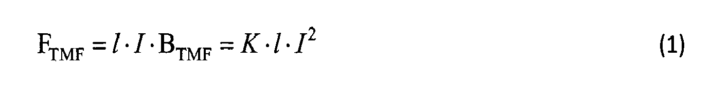
- Where l is the gap distance and I the total current flowing through the arc. For BTMF different values are possible, which also depend on details of the geometry, such as contact shape and gap distance. The proportionality factor K depends on the strength of the magnetic flux density as a function of the current.
- In the case of a magnetically driven arc, mostly a single running columnar arc for gap distances above 5mm is existing, which of course can also interact with the shield.
- Especially at high currents the dominant arc mode is no longer the columnar arc, but "anode and cathode jets vacuum arc". This arc has the tendency to move to the contact edges and form two jets into the region outside.
- The question is how these transitions to the arc modes at the contact edges appear. From the prior art, the appearance of the two-jet mode is assumed to be due to the presence of the kink-instability in a plasma column. This is one of a number of instabilities in a plasma column.
- But the kink instability occurs, if the plasma column is already distorted slightly sideways. Due to the property of the magnetic flux density being source less, a bending of a plasma column leads to an increase of the magnetic field on the inside of the bend. This leads to an increase in the magnetic force "on the inside of the kink" towards the bend direction, forcing the bended column to be bent even more.
- If a columnar arc is inside between two TMF contacts, its motion to be due dominantly by the (TMF) Lorentz force effect is expected. Therefore, a rotational motion of the arc as long as it is inside the contacts can be expected. This might lead initially to a slight arc bending, but only at the contacts edge the instability can fully develop itself and the arc is blown outside.
- The TMF forces "push" the vacuum arc to the edge and eventually blow it to the outside. From this, on the other hand, one can compare the relative importance of the driving force from the TMF magnetic field and the force driving the arc instability. This estimate can be used to get the radius of curvature R an arc must have in order to lead to a kink-instability force, which is as large than the TMF force:
- The kink-instability force F kink can be expressed in simplified way as following:

- Comparing this with the force by the TMF magnetic field from Eq. (1), the critical radius of curvature is as

- This curvature is independent of the actual short circuit current and only depends on the proportionality factor K.
- For a short circuit current I = 50kA and a gap distance of l = 10mm, a B-filed BIMF = 1.5T and a force of FTMF = 750N is chosen. Here a value of K = BIMF / I = 30mT/kA.
- For the parameters given above:

- This is of the order of the gap distance and means that unless the bending of the arc, to the outside is comparable to the driving force, we do not expect that the kink force will dominate the arc behavior. However, once the arc is established at the contacts edges, the curvature becomes more significant and the kink instability amplifies the arc bending to transform it finally to arc jets.
- One could also reduce relatively the effect of the kink-instability forces by increasing the proportionality factor K=BTMF/I which is geometry dependent.
-
- 1
- pole part
- 2
- electrical contact
- 3
- electrical connector
- 4
- vacuum housing
- 5
- jack shaft
- 6
- electromagnetic actuator
- 7
- flexible conductor
- 8
- contact shaft
- 9
- cup-shaped contact part
- 10
- contact ring
- 11
- rim section
- 12
- flange section
- 13
- first concave groove
- 14
- second concave groove
- 15
- third concave groove
- 16
- inner contact part
- X
- arc zone
Claims (10)
- Vacuum interrupter arrangement for a medium voltage circuit breaker comprising a vacuum housing (4) within which a pair of electrical contacts (2a, 2b) are coaxially arranged and concentrically surrounded by the cylindrical shaped vacuum housing (4), wherein the electrical contacts (2a, 2b) are formed in a type of TMF-contacts, each comprising a slotted cup-shaped contact part (9a; 9b) which is attached to the distal end of a contact shaft (8a; 8b) and which is covered by a contact ring (10) disposed on the rim (11) of the cup-shaped contact part (9a; 9b),
characterized in that each cup-shaped contact part (9; 9'; 9"; 9""; 9"") is provided with a vertical inward bending towards the contact ring (10), wherein the outer diameter of the bottom section of the cup-shaped contact part (9; 9'; 9"; 9""; 9"") is larger than the outer diameter of its rim section (11), in order to alter the Lorentz force on a constricted columnar arc to a respective inward direction. - Vacuum interrupter arrangement according to Claim 1,
characterized in that the vertical inward bending on the cup-shaped contact part (9) is provided with a flat flange section (12) of the cup-shaped contact part (9) which is inwardly bended. - Vacuum interrupter arrangement according to Claim 1,
characterized in that the vertical inward bending on the cup-shaped contact part (9') is provided with a concave groove (13) disposed in the inner wall of the flange section (12). - Vacuum interrupter arrangement according to Claim 1,
characterized in that the vertical inward bending on the cup-shaped contact part (9") is provided with a concave groove (14) disposed in the outer wall of the flange section (12) in the area of its rim (11). - Vacuum interrupter arrangement according to Claim 4,
characterized in that an additional concave groove (15) is disposed in the inner wall of the flange section (12) in the bottom area of the cup-shaped contact part (9"'). - Vacuum interrupter arrangement according to Claim 1,
characterized in that the contact ring (10) has the same outer diameter like the bottom section of the cup-shaped contact part (9; 9'; 9"; 9""; 9""). - Vacuum interrupter arrangement according to Claim 1,
characterized in that each electrical contact (2a; 2b) is shaped as a single cup-type TMF-contact. - Vacuum interrupter arrangement according to Claim 1,
characterized in that each electrical contact (2a; 2b) is shaped as a double-TMF contact system consisting of a discoid inner contact part (16) and a surrounding outer cup-shaped contact part (9). - Vacuum interrupter arrangement according to Claim 8,
characterized in that the inner contact part (16) is spiral slotted. - Medium voltage circuit-breaker comprising at least one vacuum interrupter arrangement as claimed in one of the preceding Claims 1 to 9 for at least one pole part (1) operated by an electromagnetic actuator (6).
Priority Applications (7)
| Application Number | Priority Date | Filing Date | Title |
|---|---|---|---|
| EP12007608.8A EP2731120A1 (en) | 2012-11-08 | 2012-11-08 | Vacuum interrupter arrangement for a medium voltage circuit breaker with cup-shaped TMF-contacts |
| PCT/EP2013/003335 WO2014072048A1 (en) | 2012-11-08 | 2013-11-06 | Vacuum interrupter arrangement for a medium voltage circuit breaker with cup-shaped tmf-contacts |
| CN201380065022.XA CN104969322A (en) | 2012-11-08 | 2013-11-06 | Vacuum interrupter arrangement for a medium voltage circuit breaker with cup-shaped TMF-contacts |
| RU2015121738A RU2612660C2 (en) | 2012-11-08 | 2013-11-06 | Vacuum circuit breaker for medium voltage circuit breaker with cup-shaped pmp-contacts |
| IN3769DEN2015 IN2015DN03769A (en) | 2012-11-08 | 2013-11-06 | |
| JP2015541034A JP2015534247A (en) | 2012-11-08 | 2013-11-06 | Vacuum interrupter device for medium voltage circuit breakers with cup-shaped TMF contacts |
| US14/707,486 US9484169B2 (en) | 2012-11-08 | 2015-05-08 | Vacuum interrupter arrangement for a medium voltage circuit breaker with cup-shaped TMF-contacts |
Applications Claiming Priority (1)
| Application Number | Priority Date | Filing Date | Title |
|---|---|---|---|
| EP12007608.8A EP2731120A1 (en) | 2012-11-08 | 2012-11-08 | Vacuum interrupter arrangement for a medium voltage circuit breaker with cup-shaped TMF-contacts |
Publications (1)
| Publication Number | Publication Date |
|---|---|
| EP2731120A1 true EP2731120A1 (en) | 2014-05-14 |
Family
ID=47189676
Family Applications (1)
| Application Number | Title | Priority Date | Filing Date |
|---|---|---|---|
| EP12007608.8A Withdrawn EP2731120A1 (en) | 2012-11-08 | 2012-11-08 | Vacuum interrupter arrangement for a medium voltage circuit breaker with cup-shaped TMF-contacts |
Country Status (7)
| Country | Link |
|---|---|
| US (1) | US9484169B2 (en) |
| EP (1) | EP2731120A1 (en) |
| JP (1) | JP2015534247A (en) |
| CN (1) | CN104969322A (en) |
| IN (1) | IN2015DN03769A (en) |
| RU (1) | RU2612660C2 (en) |
| WO (1) | WO2014072048A1 (en) |
Cited By (1)
| Publication number | Priority date | Publication date | Assignee | Title |
|---|---|---|---|---|
| CN111968877A (en) * | 2020-09-17 | 2020-11-20 | 安徽普众机电有限公司 | High-voltage vacuum circuit breaker structure |
Families Citing this family (8)
| Publication number | Priority date | Publication date | Assignee | Title |
|---|---|---|---|---|
| FR2991097B1 (en) * | 2012-05-24 | 2014-05-09 | Schneider Electric Ind Sas | ARC CONTROL DEVICE FOR VACUUM BULB |
| EP3144946A1 (en) * | 2015-09-18 | 2017-03-22 | ABB Schweiz AG | Low voltage electrical contact system with enhanced arc blow effect |
| DE102015218295A1 (en) * | 2015-09-23 | 2017-03-23 | Siemens Aktiengesellschaft | Pot contact with slanted bobbin |
| DE102015218603A1 (en) | 2015-09-28 | 2017-03-30 | Siemens Aktiengesellschaft | Pot contact with double structure |
| DE102015218616A1 (en) | 2015-09-28 | 2017-03-30 | Siemens Aktiengesellschaft | Pot contact with outer flow throughflow body |
| CN108389753B (en) * | 2018-02-07 | 2020-03-31 | 西安交通大学 | Novel cup-shaped vacuum arc-extinguishing chamber contact |
| CN108320997B (en) * | 2018-03-23 | 2019-01-08 | 西安交通大学 | Multipolar system transverse direction magnet structure direct current cut-offs vacuum interrupter and application |
| US11443910B2 (en) * | 2019-09-27 | 2022-09-13 | Gigavac, Llc | Contact levitation triggering mechanisms for use with switching devices incorporating pyrotechnic features |
Citations (5)
| Publication number | Priority date | Publication date | Assignee | Title |
|---|---|---|---|---|
| GB1095638A (en) * | 1965-12-16 | 1967-12-20 | Ass Elect Ind | Improvements in or relating to vacuum switch contacts |
| DE3035875A1 (en) * | 1980-09-23 | 1982-05-06 | Siemens AG, 1000 Berlin und 8000 München | Vacuum switch contact device for HV and heavy currents - has contact coating tapered at outer edge to direct arc inwards |
| DE3434417A1 (en) * | 1984-09-19 | 1986-03-20 | Siemens AG, 1000 Berlin und 8000 München | Contact arrangement for vacuum switches |
| WO2006002560A1 (en) | 2004-07-05 | 2006-01-12 | Abb Research Ltd | Vacuum interrupter and contact arrangement for a vacuum interrupter |
| JP2010267442A (en) * | 2009-05-13 | 2010-11-25 | Japan Ae Power Systems Corp | Vertical magnetic-field electrode for vacuum interrupter |
Family Cites Families (20)
| Publication number | Priority date | Publication date | Assignee | Title |
|---|---|---|---|---|
| JPS52155373A (en) * | 1976-05-28 | 1977-12-23 | Tokyo Shibaura Electric Co | Vacuum breaker |
| DE3332092A1 (en) * | 1983-09-02 | 1985-03-21 | Siemens AG, 1000 Berlin und 8000 München | CONTACT FOR A VACUUM SWITCH TUBE |
| US4999463A (en) * | 1988-10-18 | 1991-03-12 | Square D Company | Arc stalling eliminating device and system |
| US4982059A (en) * | 1990-01-02 | 1991-01-01 | Cooper Industries, Inc. | Axial magnetic field interrupter |
| US5438174A (en) * | 1993-11-22 | 1995-08-01 | Eaton Corporation | Vacuum interrupter with a radial magnetic field |
| KR100295905B1 (en) * | 1998-07-18 | 2001-08-07 | 이종수 | Electrode structure for vacuum interrupter |
| CN1193396C (en) * | 2001-09-12 | 2005-03-16 | 株式会社明电舍 | Vacuum circuit breaker contact and vacuum circuit breaker using said contact |
| CN100442413C (en) * | 2001-09-12 | 2008-12-10 | 株式会社明电舍 | Contact for vacuum circuit breaker and vacuum circuit breaker using said contact |
| CN2540020Y (en) * | 2002-05-31 | 2003-03-12 | 唐嘉隆 | Vacuum arc-extinguishing chamber for circuit breaker |
| DE10253866B4 (en) * | 2002-11-15 | 2005-01-05 | Siemens Ag | Contact piece with rounded slot edges |
| US7304262B2 (en) * | 2003-04-25 | 2007-12-04 | Cooper Technologies Company | Vacuum encapsulation having an empty chamber |
| DE102004031887B3 (en) * | 2004-06-30 | 2006-04-13 | Siemens Ag | Switch contact for vacuum interrupters |
| DE102006008933B4 (en) * | 2006-02-22 | 2009-06-18 | Siemens Ag | Electrical switching device |
| RU2329560C1 (en) * | 2006-12-11 | 2008-07-20 | Открытое акционерное общество "Контактор" | Automatic circuit breaker |
| ES2388554T3 (en) * | 2009-10-14 | 2012-10-16 | Abb Technology Ag | Bistable magnetic actuator for a medium voltage circuit breaker |
| CN201594490U (en) * | 2010-01-28 | 2010-09-29 | 浙江新安江开关有限公司 | Vacuum on-off tube with novel contact structure |
| JP5614721B2 (en) * | 2010-12-21 | 2014-10-29 | 株式会社明電舎 | Vacuum circuit breaker electrode |
| CN102522258B (en) * | 2011-12-09 | 2015-07-15 | 沈阳工业大学 | Disc-type gyromagnetic transverse blowing vacuum arc extinguish chamber |
| EP2787520B1 (en) * | 2013-04-02 | 2015-11-04 | ABB Technology AG | Vacuum chamber with a one-piece metallic cover for self-centering |
| US9006600B2 (en) * | 2013-06-14 | 2015-04-14 | Eaton Corporation | High current vacuum interrupter with sectional electrode and multi heat pipes |
-
2012
- 2012-11-08 EP EP12007608.8A patent/EP2731120A1/en not_active Withdrawn
-
2013
- 2013-11-06 JP JP2015541034A patent/JP2015534247A/en active Pending
- 2013-11-06 IN IN3769DEN2015 patent/IN2015DN03769A/en unknown
- 2013-11-06 RU RU2015121738A patent/RU2612660C2/en not_active IP Right Cessation
- 2013-11-06 WO PCT/EP2013/003335 patent/WO2014072048A1/en active Application Filing
- 2013-11-06 CN CN201380065022.XA patent/CN104969322A/en active Pending
-
2015
- 2015-05-08 US US14/707,486 patent/US9484169B2/en not_active Expired - Fee Related
Patent Citations (5)
| Publication number | Priority date | Publication date | Assignee | Title |
|---|---|---|---|---|
| GB1095638A (en) * | 1965-12-16 | 1967-12-20 | Ass Elect Ind | Improvements in or relating to vacuum switch contacts |
| DE3035875A1 (en) * | 1980-09-23 | 1982-05-06 | Siemens AG, 1000 Berlin und 8000 München | Vacuum switch contact device for HV and heavy currents - has contact coating tapered at outer edge to direct arc inwards |
| DE3434417A1 (en) * | 1984-09-19 | 1986-03-20 | Siemens AG, 1000 Berlin und 8000 München | Contact arrangement for vacuum switches |
| WO2006002560A1 (en) | 2004-07-05 | 2006-01-12 | Abb Research Ltd | Vacuum interrupter and contact arrangement for a vacuum interrupter |
| JP2010267442A (en) * | 2009-05-13 | 2010-11-25 | Japan Ae Power Systems Corp | Vertical magnetic-field electrode for vacuum interrupter |
Cited By (1)
| Publication number | Priority date | Publication date | Assignee | Title |
|---|---|---|---|---|
| CN111968877A (en) * | 2020-09-17 | 2020-11-20 | 安徽普众机电有限公司 | High-voltage vacuum circuit breaker structure |
Also Published As
| Publication number | Publication date |
|---|---|
| CN104969322A (en) | 2015-10-07 |
| US9484169B2 (en) | 2016-11-01 |
| JP2015534247A (en) | 2015-11-26 |
| WO2014072048A1 (en) | 2014-05-15 |
| RU2612660C2 (en) | 2017-03-13 |
| US20150248978A1 (en) | 2015-09-03 |
| RU2015121738A (en) | 2016-12-27 |
| IN2015DN03769A (en) | 2015-10-02 |
Similar Documents
| Publication | Publication Date | Title |
|---|---|---|
| EP2731120A1 (en) | Vacuum interrupter arrangement for a medium voltage circuit breaker with cup-shaped TMF-contacts | |
| EP0801798B1 (en) | Sealed relay device | |
| EP2485235B1 (en) | Vacuum interrupter for vacuum circuit breaker | |
| US9330868B2 (en) | Contact assembly for a vacuum circuit breaker | |
| EP2434513B1 (en) | Electrical contact arrangement for vacuum interrupter arrangement | |
| JP2008524815A (en) | Contact system for electrical switching devices | |
| EP2434514A1 (en) | Vacuum interrupter for a circuit breaker arrangement | |
| JPH10228848A (en) | Electric switchgear | |
| US11087940B2 (en) | Electrical interruption device | |
| TWI501280B (en) | Switchgear | |
| JP2009289660A (en) | Vacuum valve | |
| CN218730619U (en) | Electrical isolating switch | |
| JP2000268684A (en) | Switchgear | |
| RU2291513C2 (en) | Vacuum power switch | |
| CN218602329U (en) | Electrical isolating switch and switch layer thereof | |
| EP2881961A1 (en) | Low-, medium-, or high-voltage vacuum interrupter with a contact system | |
| EP2731117A1 (en) | High voltage electrical switching device with supporting tube | |
| JP4693736B2 (en) | Gas insulated disconnect switch | |
| JP5038661B2 (en) | Vacuum valve | |
| JPH04155721A (en) | Vacuum bulb | |
| JPH10321092A (en) | Bias electrode for vacuum valve and vacuum valve using the bias electrode and vacuum circuit breaker using the vacuum valve | |
| JP2013131294A (en) | Electrode for vacuum circuit breaker and vacuum circuit breaker | |
| KR20150113708A (en) | Vacuum Interrupter |
Legal Events
| Date | Code | Title | Description |
|---|---|---|---|
| PUAI | Public reference made under article 153(3) epc to a published international application that has entered the european phase |
Free format text: ORIGINAL CODE: 0009012 |
|
| 17P | Request for examination filed |
Effective date: 20121108 |
|
| AK | Designated contracting states |
Kind code of ref document: A1 Designated state(s): AL AT BE BG CH CY CZ DE DK EE ES FI FR GB GR HR HU IE IS IT LI LT LU LV MC MK MT NL NO PL PT RO RS SE SI SK SM TR |
|
| AX | Request for extension of the european patent |
Extension state: BA ME |
|
| R17P | Request for examination filed (corrected) |
Effective date: 20141103 |
|
| RBV | Designated contracting states (corrected) |
Designated state(s): AL AT BE BG CH CY CZ DE DK EE ES FI FR GB GR HR HU IE IS IT LI LT LU LV MC MK MT NL NO PL PT RO RS SE SI SK SM TR |
|
| RAP1 | Party data changed (applicant data changed or rights of an application transferred) |
Owner name: ABB SCHWEIZ AG |
|
| 17Q | First examination report despatched |
Effective date: 20161027 |
|
| GRAP | Despatch of communication of intention to grant a patent |
Free format text: ORIGINAL CODE: EPIDOSNIGR1 |
|
| INTG | Intention to grant announced |
Effective date: 20170616 |
|
| STAA | Information on the status of an ep patent application or granted ep patent |
Free format text: STATUS: THE APPLICATION IS DEEMED TO BE WITHDRAWN |
|
| 18D | Application deemed to be withdrawn |
Effective date: 20171027 |