EP1991344B1 - Flüssigkeitsbelüfter - Google Patents
Flüssigkeitsbelüfter Download PDFInfo
- Publication number
- EP1991344B1 EP1991344B1 EP07712969A EP07712969A EP1991344B1 EP 1991344 B1 EP1991344 B1 EP 1991344B1 EP 07712969 A EP07712969 A EP 07712969A EP 07712969 A EP07712969 A EP 07712969A EP 1991344 B1 EP1991344 B1 EP 1991344B1
- Authority
- EP
- European Patent Office
- Prior art keywords
- pipe
- fluid
- vessel
- aerator
- wine
- Prior art date
- Legal status (The legal status is an assumption and is not a legal conclusion. Google has not performed a legal analysis and makes no representation as to the accuracy of the status listed.)
- Not-in-force
Links
- 238000005276 aerator Methods 0.000 title claims abstract description 38
- 239000007788 liquid Substances 0.000 title claims abstract description 14
- 239000012530 fluid Substances 0.000 claims abstract description 38
- 235000014101 wine Nutrition 0.000 abstract description 65
- 239000011521 glass Substances 0.000 abstract description 14
- 238000005273 aeration Methods 0.000 description 9
- 239000000463 material Substances 0.000 description 3
- 229920003023 plastic Polymers 0.000 description 3
- 239000004033 plastic Substances 0.000 description 3
- 235000013361 beverage Nutrition 0.000 description 2
- 230000000694 effects Effects 0.000 description 2
- 239000007769 metal material Substances 0.000 description 2
- 229910000971 Silver steel Inorganic materials 0.000 description 1
- 230000006978 adaptation Effects 0.000 description 1
- 238000013019 agitation Methods 0.000 description 1
- 230000035622 drinking Effects 0.000 description 1
- 239000000796 flavoring agent Substances 0.000 description 1
- 235000019634 flavors Nutrition 0.000 description 1
- 238000000034 method Methods 0.000 description 1
- 238000007789 sealing Methods 0.000 description 1
- 239000004332 silver Substances 0.000 description 1
- 229910001220 stainless steel Inorganic materials 0.000 description 1
- 239000010935 stainless steel Substances 0.000 description 1
Images


Classifications
-
- B—PERFORMING OPERATIONS; TRANSPORTING
- B01—PHYSICAL OR CHEMICAL PROCESSES OR APPARATUS IN GENERAL
- B01F—MIXING, e.g. DISSOLVING, EMULSIFYING OR DISPERSING
- B01F23/00—Mixing according to the phases to be mixed, e.g. dispersing or emulsifying
- B01F23/20—Mixing gases with liquids
- B01F23/23—Mixing gases with liquids by introducing gases into liquid media, e.g. for producing aerated liquids
- B01F23/236—Mixing gases with liquids by introducing gases into liquid media, e.g. for producing aerated liquids specially adapted for aerating or carbonating beverages
-
- A—HUMAN NECESSITIES
- A47—FURNITURE; DOMESTIC ARTICLES OR APPLIANCES; COFFEE MILLS; SPICE MILLS; SUCTION CLEANERS IN GENERAL
- A47G—HOUSEHOLD OR TABLE EQUIPMENT
- A47G23/00—Other table equipment
-
- B—PERFORMING OPERATIONS; TRANSPORTING
- B01—PHYSICAL OR CHEMICAL PROCESSES OR APPARATUS IN GENERAL
- B01F—MIXING, e.g. DISSOLVING, EMULSIFYING OR DISPERSING
- B01F23/00—Mixing according to the phases to be mixed, e.g. dispersing or emulsifying
- B01F23/20—Mixing gases with liquids
- B01F23/23—Mixing gases with liquids by introducing gases into liquid media, e.g. for producing aerated liquids
- B01F23/234—Surface aerating
- B01F23/2341—Surface aerating by cascading, spraying or projecting a liquid into a gaseous atmosphere
- B01F23/23411—Surface aerating by cascading, spraying or projecting a liquid into a gaseous atmosphere by cascading the liquid
-
- B—PERFORMING OPERATIONS; TRANSPORTING
- B67—OPENING, CLOSING OR CLEANING BOTTLES, JARS OR SIMILAR CONTAINERS; LIQUID HANDLING
- B67C—CLEANING, FILLING WITH LIQUIDS OR SEMILIQUIDS, OR EMPTYING, OF BOTTLES, JARS, CANS, CASKS, BARRELS, OR SIMILAR CONTAINERS, NOT OTHERWISE PROVIDED FOR; FUNNELS
- B67C11/00—Funnels, e.g. for liquids
- B67C11/02—Funnels, e.g. for liquids without discharge valves
-
- B—PERFORMING OPERATIONS; TRANSPORTING
- B01—PHYSICAL OR CHEMICAL PROCESSES OR APPARATUS IN GENERAL
- B01F—MIXING, e.g. DISSOLVING, EMULSIFYING OR DISPERSING
- B01F2101/00—Mixing characterised by the nature of the mixed materials or by the application field
- B01F2101/06—Mixing of food ingredients
- B01F2101/16—Mixing wine or other alcoholic beverages; Mixing ingredients thereof
- B01F2101/17—Aeration of wine
-
- Y—GENERAL TAGGING OF NEW TECHNOLOGICAL DEVELOPMENTS; GENERAL TAGGING OF CROSS-SECTIONAL TECHNOLOGIES SPANNING OVER SEVERAL SECTIONS OF THE IPC; TECHNICAL SUBJECTS COVERED BY FORMER USPC CROSS-REFERENCE ART COLLECTIONS [XRACs] AND DIGESTS
- Y10—TECHNICAL SUBJECTS COVERED BY FORMER USPC
- Y10S—TECHNICAL SUBJECTS COVERED BY FORMER USPC CROSS-REFERENCE ART COLLECTIONS [XRACs] AND DIGESTS
- Y10S261/00—Gas and liquid contact apparatus
- Y10S261/22—Faucet aerators
Definitions
- the present invention is concerned with a liquid aerator and in particular an aerator adapted for use with small quantities of wine and other beverages known to benefit from aeration.
- the wine receptacle in FR2862241 the wine receptacle includes an agitator and in US4162129 two receptacles are interconnected to permit fluid to flow from one to the other and are attached to a motor driven oscillator.
- the wine receptacle is fed by means of a valve controlled funnel. This permits the receptacle to be tipped upside-down so that the wine may be agitated, but without any wine escaping from the end of the funnel.
- the receptacle in US5713263 is intentionally larger in capacity than a conventional wine bottle so that air remains in the receptacle even when an entire bottle has been emptied into the receptacle.
- the present invention seeks to provide a liquid aerator that is particularly adapted to aerate liquid both in larger volumes, for example 750 ml, and in smaller volumes such as that of a conventional wine glass 125 ml or 175 ml.
- the present invention therefore provides a fluid aerator in accordance with the features of claim 1, comprising a fluid vessel and a pipe extending from the interior of the fluid vessel to the exterior, the pipe having inlet means for permitting liquid to flow into the pipe from the vessel and one or more outlet holes arranged in the wall of the pipe below the inlet means, the pipe being at least partially closed at its lowermost end and being movable relative to the vessel between a first position in which the outlet holes are distant from the vessel and a second position in which the outlet holes are closer to the vessel, the fluid aerator further comprising pipe holding means for holding the pipe in at least the first and second positions.
- inlet means and outlet holes are arranged such that the rate of flow of fluid at the outlet holes is substantially the same at both the first and second positions of the pipe.
- the one or more outlet holes are arranged radially in the wall of the pipe and adjacent the lowermost closed end of the pipe.
- the inlet means comprises a perforated region of the pipe and may additionally includes a mesh filter.
- the inlet means may comprise a mesh filter inset into the wall of the pipe or a mesh filter may be provided which extends across the interior of the pipe at a position between the inlet means and the outlet hole.
- the vessel includes a plurality of fins extending outwardly from the vessel which define air channels therebetween and the one or more outlet holes are arranged with respect to the fins so that the flow of liquid from the outlet holes intersects the flow of air along the air channels.
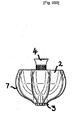
- the wine aerator 1 generally comprises a vessel or collector 2 which is open at its top and has an aperture 3 at its base and a supply pipe 4 which extends through the aperture 3 and is movable relative to the collector 2.
- the collector 2 has an inner surface 5, which in the Figures is substantially hemispherical, and which describes the boundary of a fluid collecting region 6. It will be apparent that it is not essential for the inner surface 5 of the collector to be hemispherical. Alternative shapes, for example frusto-conical, are envisaged for the inner surface of the collector as long as the shape described by the inner surface funnels liquid received in the collector towards the base of the collector.
- the outer surface of the collector 2 has a plurality of fins 7 extending outwardly from the collector.
- the fins 7 increase in size from the top rim of the collector to the aperture 3.
- the depth of the fins 7 corresponds to the length of a guide pipe which fluidly connects the fluid collecting region 6 with the aperture 3.
- the fluid aerator shown in the Figures has ten fins 7 but it will be immediately apparent that alternative numbers of fins may be employed.
- the collector diameter, measured to outside of the fins 7, varies. This enables the collector 2 to be mounted in apertures falling within a range of diameters e.g. 3 cm to 10 cm, although larger and smaller diameters are also possible, subject to the size of the collector 2.
- An o-ring or other fluid seal (not illustrated) is provided in the interior wall of the guide pipe and engages with the supply pipe 4 which is dimensioned to form a sliding fit with the walls of the guide pipe.
- the inner wall of the guide pipe functions as pipe holding means to hold the supply pipe in position relative to the guide pipe.
- the supply pipe 4 is cylindrical in the Figures, alternative shapes for the supply pipe may be employed as long as the guide pipe and aperture 3 match.
- the supply pipe 4 is closed at its lowermost end.
- a plurality of small feed holes 8 are arranged radially around the wall of the supply pipe adjacent the closed end of the supply pipe.
- the number and arrangement of the feed holes 8 may be varied.
- a single small feed hole would provide aeration of the wine but would take time to dispense the wine.
- Increasing the number of feed holes increases the speed with which the wine can be dispensed without loss of aeration function.
- the supply pipe 4 need not be fully closed at its lowermost end. Instead, the end of the supply pipe 4 may be adapted to restrict the flow of wine so that wine is caused to flow from both the end of the pipe and the one or more feed holes 8 arranged in the wall of the supply pipe.
- an upper region 9 of the supply pipe, above the feed holes 8, is perforated to function as a liquid inlet means; the perforations providing fluid passage between the exterior and the interior of the supply pipe 4.
- the supply pipe 4 additionally includes a radially extending rib 10.
- the rib 10 acts as a detent which engages with the guide pipe so as to restrict further movement of the supply pipe in a downward direction beyond a predetermined position.
- the supply pipe is arranged for substantially fluid-sealing but sliding movement relative to the collector 2.
- the supply pipe 4 In a first position, illustrated in Figures 1 and 2 , the supply pipe 4 is at its most downward position in which the feed holes 8 are distant from the aperture 3 in the collector.
- a second position, illustrated in Figure 3 the supply pipe is at its uppermost position in which the feed holes 8 are positioned closer, and preferably adjacent, the aperture 3 of the collector.
- the guide pipe acts to hold the supply pipe in these positions and in any position between these two extremes.
- the wine aerator 1 is positioned in the opening of the receptacle into which the wine or other fluid is to be poured. Where an entire bottle of wine (e.g. 750 ml) is to be aerated, the supply pipe 4 is placed in its first position with the feed holes 8 distant from the aperture 3. Moreover, in this first position the wine aerator 1 is fully capable of handling even larger volumes of wine such as the volumes found with methusaleh and salmanazar sized bottles.
- the adjustable position of the supply pipe 4 relative to the collector 2 is required so as to ensure that the feed holes 8 in the supply pipe do not become submerged as the glass or other receptacle is being filled.
- the first position of the supply pipe 4, in which the feed holes 8 are distant from the aperture 3, generally achieves greater aeration of the wine, as greater air circulation can be achieved.
- the supply pipe 4 by enabling the supply pipe 4 to be movable to a second position where the feed holes 8 are adjacent the aperture 3, it is still possible to ensure aeration of a significant proportion of the wine even where the receptacle is to be filled close to its uppermost edge. In this way, smaller volumes of wine, namely less than 750 ml, and more preferably 250 ml or less, may be aerated directly into a glass or other small volume receptacle.
- the inner surface of the collector 2 may include one or more markings (not illustrated) to indicate the level to which the collector 2 should be filled with wine in order to dispense a standard wine glass measure (e.g. 125 ml or 175 ml).
- a standard wine glass measure e.g. 125 ml or 175 ml
- the engagement of the fins 7, provided on the exterior of the collector 2, with the opening of the wine glass or other receptacle defines a plurality of air passages or channels therebetween.
- the fins 7 are arranged so that the air passages are aligned with one or more of the feed holes 8. These air passages are believed to provide additional aeration to the wine as it flows from the feed holes 8. This is believed to be because the flow of wine intersects the natural flow of air along the air passages, resulting in a greater agitation of the air and the wine further increasing the percentage of wine which is successfully exposed to the air.
- the wine aerator describe above is a simple yet efficient means for aerating both larger quantities of wine, such as an entire bottle or more, and smaller quantities of wine such as a single glass.
- larger quantities of wine such as an entire bottle or more
- smaller quantities of wine such as a single glass.
- the perforations 9 in the supply pipe are replaced with a mesh which acts as a filter preventing any residue or other foreign bodies passing from the collector 2 to the feed holes 8.
- the mesh may be additional to the perforations or may be arranged to extend across the interior of the supply pipe 4 below the perforated region 9 but above the feed holes 8.
- the collector may be made of a metallic material which is substantially inert in the presence of liquids such as wine. Examples of suitable metallic materials are silver or stainless steel.
- the collector may be made of a hard plastics material. In the latter case, the plastics material is preferably partially translucent so that the collector appears striped as a result of the greater thickness of each of the fins relative to the wall of the collector between the fins. The plastics material may additionally be coloured to emphasise the striped effect.
Landscapes
- Chemical & Material Sciences (AREA)
- Chemical Kinetics & Catalysis (AREA)
- Devices For Dispensing Beverages (AREA)
- Filling Of Jars Or Cans And Processes For Cleaning And Sealing Jars (AREA)
- Aeration Devices For Treatment Of Activated Polluted Sludge (AREA)
- Table Devices Or Equipment (AREA)
- Cosmetics (AREA)
- Agricultural Chemicals And Associated Chemicals (AREA)
- Apparatus Associated With Microorganisms And Enzymes (AREA)
Claims (11)
- Flüssigkeitsbelüfter, umfassend ein Flüssigkeitsgefäß (2) und ein Rohr (4), das aus dem Inneren des Flüssigkeitsgefäßes (2) heraus nach außen verläuft, wobei das Rohr (4) über Einlassmittel (9) verfügt, die das Einlaufen von Flüssigkeit in das Rohr (4) aus dem Gefäß (2) ermöglichen, und über ein oder mehrere Auslasslöcher (8) verfügt, die unterhalb der Einlassmittel (9) in der Wand des Rohrs (4) angeordnet sind, wobei das Rohr (4) an seinem untersten Ende zumindest teilweise verschlossen ist und der Flüssigkeitsbelüfter dadurch gekennzeichnet ist, dass das Rohr (4) im Verhältnis zu dem Gefäß (2) beweglich ist zwischen einer ersten Position, in der sich die Auslasslöcher (8) entfernt vom Gefäß (2) befinden, und einer zweiten Position, in der sich die Auslasslöcher (8) näher zum Gefäß (2) befinden, und dass der Flüssigkeitsbelüfter (1) des Weiteren Rohrhaltemittel (10) zum Halten des Rohrs (4) in mindestens der ersten und der zweiten Position umfasst.
- Flüssigkeitsbelüfter gemäß Anspruch 1, wobei die Einlassmittel (9) und die Auslasslöcher (8) so angeordnet sind, dass die Flüssigkeitsdurchflussrate an den Auslasslöchern (8) sowohl in der ersten als auch in der zweiten Position des Rohrs (4) im Wesentlichen dieselbe ist.
- Flüssigkeitsbelüfter gemäß Anspruch 1 oder 2, wobei das eine oder die mehreren Auslasslöcher (8) radial in der Wand des Rohrs (4) angeordnet sind.
- Flüssigkeitsbelüfter gemäß einem der Ansprüche 1 bis 3, wobei sich das eine oder die mehreren Auslasslöcher (8) in unmittelbarer Nähe zum untersten verschlossenen Ende des Rohrs (4) befindet bzw. befinden.
- Flüssigkeitsbelüfter gemäß einem der vorherigen Ansprüche, wobei das Rohr (4) einen Flüssigkeitsverschluss mit dem Gefäß (2) bildet.
- Flüssigkeitsbelüfter gemäß einem der vorherigen Ansprüche, wobei die Einlassmittel (9) einen perforierten Bereich des Rohrs (4) umfassen.
- Flüssigkeitsbelüfter gemäß Anspruch 6, wobei der perforierte Bereich (9) zusätzlich einen Siebfilter enthält.
- Flüssigkeitsbelüfter gemäß einem der Ansprüche 1 bis 5, wobei die Einlassmittel (9) einen Siebfilter, der in der Wand des Rohrs (4) eingesetzt ist, umfassen.
- Flüssigkeitsbelüfter gemäß einem der Ansprüche 1 bis 5, wobei sich ein Siebfilter an einer Position zwischen den Einlassmitteln (9) und dem Auslassloch (8) über das Innere des Rohrs (4) erstreckt.
- Flüssigkeitsbelüfter gemäß einem der vorherigen Ansprüche, wobei das Gefäß (2) eine Mehrzahl von sich von dem Gefäß (2) aus nach außen erstreckende Rippen (7) enthält, welche Luftkanäle zwischen sich definieren.
- Flüssigkeitsbelüfter gemäß Anspruch 10, wobei das eine oder die mehreren Auslasslöcher (8) in Bezug auf die Rippen (7) so angeordnet sind, dass der Flüssigkeitsdurchfluss aus den Auslasslöchern (8) die Strömung der Luft entlang den Luftkanälen kreuzt.
Applications Claiming Priority (2)
| Application Number | Priority Date | Filing Date | Title |
|---|---|---|---|
| GBGB0603834.3A GB0603834D0 (en) | 2006-02-27 | 2006-02-27 | Liquid aerator |
| PCT/GB2007/050086 WO2007096676A1 (en) | 2006-02-27 | 2007-02-27 | Liquid aerator |
Publications (2)
| Publication Number | Publication Date |
|---|---|
| EP1991344A1 EP1991344A1 (de) | 2008-11-19 |
| EP1991344B1 true EP1991344B1 (de) | 2010-03-17 |
Family
ID=36178792
Family Applications (1)
| Application Number | Title | Priority Date | Filing Date |
|---|---|---|---|
| EP07712969A Not-in-force EP1991344B1 (de) | 2006-02-27 | 2007-02-27 | Flüssigkeitsbelüfter |
Country Status (10)
| Country | Link |
|---|---|
| US (1) | US8196906B2 (de) |
| EP (1) | EP1991344B1 (de) |
| JP (1) | JP4980378B2 (de) |
| CN (1) | CN101421026B (de) |
| AT (1) | ATE460975T1 (de) |
| AU (1) | AU2007217153B2 (de) |
| DE (1) | DE602007005359D1 (de) |
| ES (1) | ES2342687T3 (de) |
| GB (1) | GB0603834D0 (de) |
| WO (1) | WO2007096676A1 (de) |
Families Citing this family (36)
| Publication number | Priority date | Publication date | Assignee | Title |
|---|---|---|---|---|
| US20100058933A1 (en) * | 2008-09-11 | 2010-03-11 | Cheng Peter S | Wine aerator |
| US8101222B2 (en) * | 2008-11-18 | 2012-01-24 | Chevalier Collection, Ltd. | Beverage glass with internal decanting, filtering, mixing and aerating cell |
| US8757048B2 (en) | 2008-11-18 | 2014-06-24 | James R. Burroughs | Beverage glass with internal decanting, filtering, mixing and aerating cell |
| US20110005401A1 (en) | 2008-11-18 | 2011-01-13 | Chevalier Collection Ltd. | Beverage glass with internal decanting, filtering,mixing and aerating cell |
| CN101824375A (zh) * | 2009-11-27 | 2010-09-08 | 林波 | 彩虹鸡尾酒调制机 |
| JP4937420B2 (ja) * | 2010-03-23 | 2012-05-23 | 株式会社薬膳壷焼本舗五行 | 流体下降装置及びその支持具 |
| US8430023B2 (en) * | 2010-05-04 | 2013-04-30 | India Hynes | Adjustable wine aerator |
| US8807358B2 (en) | 2010-09-29 | 2014-08-19 | Mars Aerator Llc | Within bottle aerator |
| US9033187B2 (en) | 2010-10-06 | 2015-05-19 | Aerawine Llc | Bottle top liquid aerator |
| US8590865B2 (en) | 2011-08-11 | 2013-11-26 | Vinomax Llc | Liquid aerator |
| US8727324B2 (en) | 2011-12-02 | 2014-05-20 | Prime Wine Products Llc | Wine aerator |
| US9649606B2 (en) | 2012-02-06 | 2017-05-16 | Jason Ruff | Method and apparatus for aerating liquid |
| US20130255505A1 (en) * | 2012-03-29 | 2013-10-03 | James M. Verbicky | Venturi-Type Wine Aerator With Adjustable Aeration |
| WO2013166181A2 (en) | 2012-05-02 | 2013-11-07 | Connors Robert W | Gas diffusion apparatus for liquid aeration and carbonated liquids |
| US9204744B2 (en) * | 2012-05-24 | 2015-12-08 | Margarita D. Vacanti | Drinkware |
| US9283526B2 (en) * | 2012-05-31 | 2016-03-15 | Owens-Brockway Glass Container Inc. | Beverage aeration |
| USD696067S1 (en) | 2012-07-20 | 2013-12-24 | Margarita D. Vacanti | Drinkware |
| CA2795974A1 (en) * | 2012-11-14 | 2014-05-14 | Gabriel Castanon | Wine aerator |
| USD732890S1 (en) | 2012-11-27 | 2015-06-30 | Robert W. Connors | Gas diffusion apparatus |
| US8561970B1 (en) * | 2013-01-23 | 2013-10-22 | Brookstone Purchasing, Inc. | Aeration system |
| US20140263461A1 (en) * | 2013-03-13 | 2014-09-18 | David M. Prokop | Motorized aerator pourer |
| DE102013114391A1 (de) | 2013-12-18 | 2015-06-18 | Airbus Operations Gmbh | Druckrumpf eines Flugzeuges, umfassend ein bewegbar relativ zur Rumpfstruktur befestigtes Druckschott |
| US9795934B2 (en) | 2015-01-12 | 2017-10-24 | Robert W. Connors | Wine and spirits aerator |
| CN107921380B (zh) | 2015-03-19 | 2020-09-08 | 赛菲特有限责任公司 | 用于选择性地使饮料充气的组件 |
| WO2018058142A1 (en) * | 2016-09-26 | 2018-03-29 | Amnity Llc | A tap and aerator apparatus |
| US10328397B2 (en) * | 2016-11-03 | 2019-06-25 | Kyle Perfette | Systems and methods for a wine aeration apparatus |
| US11219871B2 (en) * | 2017-03-10 | 2022-01-11 | Pronto Concepts Inc. | Liquid diffusing filter |
| ES2961588T3 (es) | 2017-04-12 | 2024-03-12 | Gaia Usa Inc | Aparato y procedimiento para generar y mezclar burbujas de gas ultrafinas en una solución acuosa de alta concentración de gas |
| US11000813B2 (en) * | 2017-11-21 | 2021-05-11 | Rocco Giardullo | Beverage aerator, beverage decanter, and related methods |
| US11084708B2 (en) * | 2018-01-19 | 2021-08-10 | Vijay Singh | Compact apparatus for fermentation and pressing of wine |
| USD855392S1 (en) | 2018-04-10 | 2019-08-06 | Greenfield World Trade, Inc. | Wine aerator |
| CA3086300C (en) | 2018-06-01 | 2021-07-13 | Gaia Usa, Inc. | Apparatus in the form of a unitary, single-piece structure configured to generate and mix ultra-fine gas bubbles into a high gas concentration aqueous solution |
| US12357952B2 (en) | 2020-12-07 | 2025-07-15 | Üllo LLC | Assembly for selectively aerating and changing the temperature of a beverage |
| US12420244B2 (en) | 2021-01-07 | 2025-09-23 | Üllo LLC | Assembly for selectively aerating a beverage |
| US11980853B2 (en) * | 2021-12-01 | 2024-05-14 | Gennady Bekker | Wine aeration devices and methods of aerating wine |
| USD1121102S1 (en) * | 2023-10-06 | 2026-03-31 | Design Bunker, Inc. | Aerator |
Family Cites Families (22)
| Publication number | Priority date | Publication date | Assignee | Title |
|---|---|---|---|---|
| US2818090A (en) * | 1954-09-27 | 1957-12-31 | Paroselite Cayetano Francisco | Funnels with automatic sealing |
| DE2729379C2 (de) * | 1976-07-07 | 1987-03-26 | Gernot Dr.rer.nat. Donnerskirchen Graefe | Verfahren zur Herstellung eines Düngemittels aus Traubentrester |
| US4042510A (en) * | 1976-09-02 | 1977-08-16 | Canton Textile Mills, Inc. | Liquid aeration device |
| US4162129A (en) | 1977-08-29 | 1979-07-24 | Wine Breather, Inc. | Wine aerator |
| US4494452A (en) | 1983-05-02 | 1985-01-22 | Craig Barzso | Wine aerator |
| CA1259304A (en) * | 1985-09-06 | 1989-09-12 | Hans C. Rasmusen | Motionless mixer for gas/liquid mixing |
| AU648910B2 (en) | 1991-06-13 | 1994-05-05 | Alun Frederich Bartsch | Wine breather |
| JPH0699937A (ja) * | 1992-09-24 | 1994-04-12 | Toyo Jidoki Co Ltd | 液状物の充填装置 |
| US5713263A (en) | 1995-06-14 | 1998-02-03 | Burks, Iii; Vance R. | Wine aerator |
| CN2242887Y (zh) * | 1995-10-26 | 1996-12-18 | 陈庭良 | 组合式散流曝气器 |
| US5762833A (en) * | 1996-09-09 | 1998-06-09 | Aeromix Systems, Inc. | Aerator with a removable stator and method of repairing the same |
| DE29723901U1 (de) | 1997-11-19 | 1999-08-12 | Klingenberg, Gero, 14197 Berlin | Einrichtung zur Belüftung von Flüssigkeiten |
| US5931382A (en) * | 1997-12-19 | 1999-08-03 | Aeromix Systems, Inc. | Aerating fountain with selectable nozzle |
| BE1011884A7 (nl) * | 1998-04-23 | 2000-02-01 | New Art Graphic Nv Sa | Het verluchten van wijn. |
| USD472096S1 (en) | 2002-08-30 | 2003-03-25 | Sharper Image Corporation | Wine aerator |
| ITTO20021012A1 (it) * | 2002-11-20 | 2004-05-21 | Gimar Tecno S R L | Dispositivo ausiliario di irrorazione e ricircolo per |
| FR2862241B1 (fr) | 2003-11-13 | 2006-03-17 | Eurl Ingimeca | Appareil viticole de pulverisation d'un liquide a l'interieur d'une cuve de reserve de vins, pour le brassage de ce vin en cours d'elaboration et/ou pour le lavage de cette cuve. |
| US7299743B2 (en) * | 2004-03-16 | 2007-11-27 | Moore James R | Aerating decanter with dispensing valve |
| CN2760015Y (zh) * | 2004-12-21 | 2006-02-22 | 上海万森水处理有限公司 | 双层布气散流式曝气器 |
| USD535559S1 (en) * | 2006-03-08 | 2007-01-23 | Concept Solutions Limited | Wine aerator |
| AU321796S (en) * | 2008-01-18 | 2008-10-30 | Westport Global Ltd | Wine aerator |
| USD619431S1 (en) * | 2008-05-07 | 2010-07-13 | Barry Wax | Wine aerator |
-
2006
- 2006-02-27 GB GBGB0603834.3A patent/GB0603834D0/en not_active Ceased
-
2007
- 2007-02-27 EP EP07712969A patent/EP1991344B1/de not_active Not-in-force
- 2007-02-27 DE DE602007005359T patent/DE602007005359D1/de active Active
- 2007-02-27 WO PCT/GB2007/050086 patent/WO2007096676A1/en not_active Ceased
- 2007-02-27 AU AU2007217153A patent/AU2007217153B2/en not_active Ceased
- 2007-02-27 ES ES07712969T patent/ES2342687T3/es active Active
- 2007-02-27 AT AT07712969T patent/ATE460975T1/de not_active IP Right Cessation
- 2007-02-27 CN CN2007800129097A patent/CN101421026B/zh not_active Expired - Fee Related
- 2007-02-27 US US12/224,452 patent/US8196906B2/en not_active Expired - Fee Related
- 2007-02-27 JP JP2008555884A patent/JP4980378B2/ja not_active Expired - Fee Related
Also Published As
| Publication number | Publication date |
|---|---|
| JP4980378B2 (ja) | 2012-07-18 |
| ES2342687T3 (es) | 2010-07-12 |
| HK1119995A1 (en) | 2009-03-20 |
| WO2007096676A1 (en) | 2007-08-30 |
| EP1991344A1 (de) | 2008-11-19 |
| AU2007217153A1 (en) | 2007-08-30 |
| AU2007217153B2 (en) | 2011-03-10 |
| US20100025867A1 (en) | 2010-02-04 |
| GB0603834D0 (en) | 2006-04-05 |
| DE602007005359D1 (de) | 2010-04-29 |
| US8196906B2 (en) | 2012-06-12 |
| JP2009528223A (ja) | 2009-08-06 |
| CN101421026A (zh) | 2009-04-29 |
| CN101421026B (zh) | 2011-08-31 |
| ATE460975T1 (de) | 2010-04-15 |
Similar Documents
| Publication | Publication Date | Title |
|---|---|---|
| EP1991344B1 (de) | Flüssigkeitsbelüfter | |
| US20160039583A1 (en) | Continuous, Complete, Automatic, Non-Leaking, Non-Aerating, Positive Pressure One-Piece Vent And Pouring Combination Utilizing One Direct Venting Aperture | |
| US6035907A (en) | Combined measuring cup, funnel and strainer utensil | |
| EP2415705B1 (de) | Getränkespender | |
| US8783665B2 (en) | Interchangeable bottletop aerator | |
| EP3324804B1 (de) | Lebensmittelverarbeitungssystem mit einer leitströmungsanordnung und verfahren zur verwendung davon | |
| CA2327821C (en) | Transfer funnel | |
| GB2419586A (en) | Drink pouring dispenser | |
| US20130202757A1 (en) | Apparatus for aerating and filtering wine | |
| US8631814B2 (en) | Flow control device | |
| JPS6077872A (ja) | 插入式注出器 | |
| HK1119995B (en) | Liquid aerator | |
| US20230030350A1 (en) | Multipurpose Vented Funnel | |
| KR20090057098A (ko) | 워터 디스펜서용 물이송 제어수단 | |
| KR20170081794A (ko) | 주류 혼합장치 | |
| US20070235103A1 (en) | Method and apparatus for forming an unmixed layer of a first liquid in or on a second liquid contained in a vessel | |
| JP7687092B2 (ja) | 混合装置 | |
| GB2433252A (en) | Pouring aid having a telescopic funnel | |
| PL239529B1 (pl) | Nalewak maszyny rozlewniczej do napełniania butelek mlekiem | |
| EP1413525A1 (de) | Ausgiesser | |
| HK1024741A (en) | Combined measuring cup, funnel and strainer utensil | |
| AU2012202447A1 (en) | Drink pouring dispenser | |
| AU2005201418A1 (en) | Drink pouring dispenser |
Legal Events
| Date | Code | Title | Description |
|---|---|---|---|
| PUAI | Public reference made under article 153(3) epc to a published international application that has entered the european phase |
Free format text: ORIGINAL CODE: 0009012 |
|
| 17P | Request for examination filed |
Effective date: 20080919 |
|
| AK | Designated contracting states |
Kind code of ref document: A1 Designated state(s): AT BE BG CH CY CZ DE DK EE ES FI FR GB GR HU IE IS IT LI LT LU LV MC NL PL PT RO SE SI SK TR |
|
| RAP1 | Party data changed (applicant data changed or rights of an application transferred) |
Owner name: WESTPORT GLOBAL LIMITED |
|
| REG | Reference to a national code |
Ref country code: HK Ref legal event code: DE Ref document number: 1119995 Country of ref document: HK |
|
| GRAP | Despatch of communication of intention to grant a patent |
Free format text: ORIGINAL CODE: EPIDOSNIGR1 |
|
| RIC1 | Information provided on ipc code assigned before grant |
Ipc: B67C 11/02 20060101ALI20090928BHEP Ipc: A47G 19/00 20060101ALI20090928BHEP Ipc: B01F 3/04 20060101AFI20090928BHEP |
|
| GRAS | Grant fee paid |
Free format text: ORIGINAL CODE: EPIDOSNIGR3 |
|
| GRAA | (expected) grant |
Free format text: ORIGINAL CODE: 0009210 |
|
| AK | Designated contracting states |
Kind code of ref document: B1 Designated state(s): AT BE BG CH CY CZ DE DK EE ES FI FR GB GR HU IE IS IT LI LT LU LV MC NL PL PT RO SE SI SK TR |
|
| REG | Reference to a national code |
Ref country code: GB Ref legal event code: FG4D |
|
| REG | Reference to a national code |
Ref country code: CH Ref legal event code: EP |
|
| REG | Reference to a national code |
Ref country code: IE Ref legal event code: FG4D |
|
| REF | Corresponds to: |
Ref document number: 602007005359 Country of ref document: DE Date of ref document: 20100429 Kind code of ref document: P |
|
| REG | Reference to a national code |
Ref country code: HK Ref legal event code: GR Ref document number: 1119995 Country of ref document: HK |
|
| REG | Reference to a national code |
Ref country code: SE Ref legal event code: TRGR |
|
| REG | Reference to a national code |
Ref country code: ES Ref legal event code: FG2A Ref document number: 2342687 Country of ref document: ES Kind code of ref document: T3 |
|
| REG | Reference to a national code |
Ref country code: NL Ref legal event code: VDEP Effective date: 20100317 |
|
| PG25 | Lapsed in a contracting state [announced via postgrant information from national office to epo] |
Ref country code: LT Free format text: LAPSE BECAUSE OF FAILURE TO SUBMIT A TRANSLATION OF THE DESCRIPTION OR TO PAY THE FEE WITHIN THE PRESCRIBED TIME-LIMIT Effective date: 20100317 |
|
| LTIE | Lt: invalidation of european patent or patent extension |
Effective date: 20100317 |
|
| PG25 | Lapsed in a contracting state [announced via postgrant information from national office to epo] |
Ref country code: AT Free format text: LAPSE BECAUSE OF FAILURE TO SUBMIT A TRANSLATION OF THE DESCRIPTION OR TO PAY THE FEE WITHIN THE PRESCRIBED TIME-LIMIT Effective date: 20100317 Ref country code: LV Free format text: LAPSE BECAUSE OF FAILURE TO SUBMIT A TRANSLATION OF THE DESCRIPTION OR TO PAY THE FEE WITHIN THE PRESCRIBED TIME-LIMIT Effective date: 20100317 Ref country code: SI Free format text: LAPSE BECAUSE OF FAILURE TO SUBMIT A TRANSLATION OF THE DESCRIPTION OR TO PAY THE FEE WITHIN THE PRESCRIBED TIME-LIMIT Effective date: 20100317 Ref country code: PL Free format text: LAPSE BECAUSE OF FAILURE TO SUBMIT A TRANSLATION OF THE DESCRIPTION OR TO PAY THE FEE WITHIN THE PRESCRIBED TIME-LIMIT Effective date: 20100317 Ref country code: FI Free format text: LAPSE BECAUSE OF FAILURE TO SUBMIT A TRANSLATION OF THE DESCRIPTION OR TO PAY THE FEE WITHIN THE PRESCRIBED TIME-LIMIT Effective date: 20100317 |
|
| PG25 | Lapsed in a contracting state [announced via postgrant information from national office to epo] |
Ref country code: EE Free format text: LAPSE BECAUSE OF FAILURE TO SUBMIT A TRANSLATION OF THE DESCRIPTION OR TO PAY THE FEE WITHIN THE PRESCRIBED TIME-LIMIT Effective date: 20100317 Ref country code: CY Free format text: LAPSE BECAUSE OF FAILURE TO SUBMIT A TRANSLATION OF THE DESCRIPTION OR TO PAY THE FEE WITHIN THE PRESCRIBED TIME-LIMIT Effective date: 20100317 Ref country code: BE Free format text: LAPSE BECAUSE OF FAILURE TO SUBMIT A TRANSLATION OF THE DESCRIPTION OR TO PAY THE FEE WITHIN THE PRESCRIBED TIME-LIMIT Effective date: 20100317 Ref country code: RO Free format text: LAPSE BECAUSE OF FAILURE TO SUBMIT A TRANSLATION OF THE DESCRIPTION OR TO PAY THE FEE WITHIN THE PRESCRIBED TIME-LIMIT Effective date: 20100317 Ref country code: NL Free format text: LAPSE BECAUSE OF FAILURE TO SUBMIT A TRANSLATION OF THE DESCRIPTION OR TO PAY THE FEE WITHIN THE PRESCRIBED TIME-LIMIT Effective date: 20100317 Ref country code: GR Free format text: LAPSE BECAUSE OF FAILURE TO SUBMIT A TRANSLATION OF THE DESCRIPTION OR TO PAY THE FEE WITHIN THE PRESCRIBED TIME-LIMIT Effective date: 20100618 |
|
| PG25 | Lapsed in a contracting state [announced via postgrant information from national office to epo] |
Ref country code: BG Free format text: LAPSE BECAUSE OF FAILURE TO SUBMIT A TRANSLATION OF THE DESCRIPTION OR TO PAY THE FEE WITHIN THE PRESCRIBED TIME-LIMIT Effective date: 20100617 Ref country code: SK Free format text: LAPSE BECAUSE OF FAILURE TO SUBMIT A TRANSLATION OF THE DESCRIPTION OR TO PAY THE FEE WITHIN THE PRESCRIBED TIME-LIMIT Effective date: 20100317 Ref country code: IS Free format text: LAPSE BECAUSE OF FAILURE TO SUBMIT A TRANSLATION OF THE DESCRIPTION OR TO PAY THE FEE WITHIN THE PRESCRIBED TIME-LIMIT Effective date: 20100717 Ref country code: CZ Free format text: LAPSE BECAUSE OF FAILURE TO SUBMIT A TRANSLATION OF THE DESCRIPTION OR TO PAY THE FEE WITHIN THE PRESCRIBED TIME-LIMIT Effective date: 20100317 |
|
| PLBE | No opposition filed within time limit |
Free format text: ORIGINAL CODE: 0009261 |
|
| STAA | Information on the status of an ep patent application or granted ep patent |
Free format text: STATUS: NO OPPOSITION FILED WITHIN TIME LIMIT |
|
| PG25 | Lapsed in a contracting state [announced via postgrant information from national office to epo] |
Ref country code: PT Free format text: LAPSE BECAUSE OF FAILURE TO SUBMIT A TRANSLATION OF THE DESCRIPTION OR TO PAY THE FEE WITHIN THE PRESCRIBED TIME-LIMIT Effective date: 20100719 Ref country code: DK Free format text: LAPSE BECAUSE OF FAILURE TO SUBMIT A TRANSLATION OF THE DESCRIPTION OR TO PAY THE FEE WITHIN THE PRESCRIBED TIME-LIMIT Effective date: 20100317 |
|
| 26N | No opposition filed |
Effective date: 20101220 |
|
| PG25 | Lapsed in a contracting state [announced via postgrant information from national office to epo] |
Ref country code: MC Free format text: LAPSE BECAUSE OF NON-PAYMENT OF DUE FEES Effective date: 20110228 |
|
| REG | Reference to a national code |
Ref country code: CH Ref legal event code: PL |
|
| PG25 | Lapsed in a contracting state [announced via postgrant information from national office to epo] |
Ref country code: LI Free format text: LAPSE BECAUSE OF NON-PAYMENT OF DUE FEES Effective date: 20110228 Ref country code: CH Free format text: LAPSE BECAUSE OF NON-PAYMENT OF DUE FEES Effective date: 20110228 |
|
| REG | Reference to a national code |
Ref country code: IE Ref legal event code: MM4A |
|
| PG25 | Lapsed in a contracting state [announced via postgrant information from national office to epo] |
Ref country code: IE Free format text: LAPSE BECAUSE OF NON-PAYMENT OF DUE FEES Effective date: 20110227 |
|
| PG25 | Lapsed in a contracting state [announced via postgrant information from national office to epo] |
Ref country code: LU Free format text: LAPSE BECAUSE OF NON-PAYMENT OF DUE FEES Effective date: 20110227 |
|
| PG25 | Lapsed in a contracting state [announced via postgrant information from national office to epo] |
Ref country code: TR Free format text: LAPSE BECAUSE OF FAILURE TO SUBMIT A TRANSLATION OF THE DESCRIPTION OR TO PAY THE FEE WITHIN THE PRESCRIBED TIME-LIMIT Effective date: 20100317 |
|
| PG25 | Lapsed in a contracting state [announced via postgrant information from national office to epo] |
Ref country code: HU Free format text: LAPSE BECAUSE OF FAILURE TO SUBMIT A TRANSLATION OF THE DESCRIPTION OR TO PAY THE FEE WITHIN THE PRESCRIBED TIME-LIMIT Effective date: 20100317 |
|
| REG | Reference to a national code |
Ref country code: FR Ref legal event code: PLFP Year of fee payment: 9 |
|
| REG | Reference to a national code |
Ref country code: FR Ref legal event code: PLFP Year of fee payment: 10 |
|
| REG | Reference to a national code |
Ref country code: FR Ref legal event code: PLFP Year of fee payment: 11 |
|
| REG | Reference to a national code |
Ref country code: FR Ref legal event code: PLFP Year of fee payment: 12 |
|
| PGFP | Annual fee paid to national office [announced via postgrant information from national office to epo] |
Ref country code: ES Payment date: 20190301 Year of fee payment: 13 Ref country code: IT Payment date: 20190226 Year of fee payment: 13 |
|
| PGFP | Annual fee paid to national office [announced via postgrant information from national office to epo] |
Ref country code: SE Payment date: 20190221 Year of fee payment: 13 Ref country code: DE Payment date: 20190227 Year of fee payment: 13 Ref country code: FR Payment date: 20190227 Year of fee payment: 13 |
|
| REG | Reference to a national code |
Ref country code: DE Ref legal event code: R119 Ref document number: 602007005359 Country of ref document: DE |
|
| REG | Reference to a national code |
Ref country code: SE Ref legal event code: EUG |
|
| PG25 | Lapsed in a contracting state [announced via postgrant information from national office to epo] |
Ref country code: SE Free format text: LAPSE BECAUSE OF NON-PAYMENT OF DUE FEES Effective date: 20200228 |
|
| PG25 | Lapsed in a contracting state [announced via postgrant information from national office to epo] |
Ref country code: FR Free format text: LAPSE BECAUSE OF NON-PAYMENT OF DUE FEES Effective date: 20200229 Ref country code: DE Free format text: LAPSE BECAUSE OF NON-PAYMENT OF DUE FEES Effective date: 20200901 |
|
| REG | Reference to a national code |
Ref country code: ES Ref legal event code: FD2A Effective date: 20210708 |
|
| PG25 | Lapsed in a contracting state [announced via postgrant information from national office to epo] |
Ref country code: IT Free format text: LAPSE BECAUSE OF NON-PAYMENT OF DUE FEES Effective date: 20200227 |
|
| PG25 | Lapsed in a contracting state [announced via postgrant information from national office to epo] |
Ref country code: ES Free format text: LAPSE BECAUSE OF NON-PAYMENT OF DUE FEES Effective date: 20200228 |
|
| PGFP | Annual fee paid to national office [announced via postgrant information from national office to epo] |
Ref country code: GB Payment date: 20230331 Year of fee payment: 17 |
|
| GBPC | Gb: european patent ceased through non-payment of renewal fee |
Effective date: 20240227 |
|
| PG25 | Lapsed in a contracting state [announced via postgrant information from national office to epo] |
Ref country code: GB Free format text: LAPSE BECAUSE OF NON-PAYMENT OF DUE FEES Effective date: 20240227 |
|
| PG25 | Lapsed in a contracting state [announced via postgrant information from national office to epo] |
Ref country code: GB Free format text: LAPSE BECAUSE OF NON-PAYMENT OF DUE FEES Effective date: 20240227 |