EP1990895A2 - Stress distributing permanent magnet rotor geometry for electric machines - Google Patents
Stress distributing permanent magnet rotor geometry for electric machines Download PDFInfo
- Publication number
- EP1990895A2 EP1990895A2 EP07024336A EP07024336A EP1990895A2 EP 1990895 A2 EP1990895 A2 EP 1990895A2 EP 07024336 A EP07024336 A EP 07024336A EP 07024336 A EP07024336 A EP 07024336A EP 1990895 A2 EP1990895 A2 EP 1990895A2
- Authority
- EP
- European Patent Office
- Prior art keywords
- permanent magnet
- recited
- rotor
- magnets
- rotor core
- Prior art date
- Legal status (The legal status is an assumption and is not a legal conclusion. Google has not performed a legal analysis and makes no representation as to the accuracy of the status listed.)
- Granted
Links
Images




Classifications
-
- H—ELECTRICITY
- H02—GENERATION; CONVERSION OR DISTRIBUTION OF ELECTRIC POWER
- H02K—DYNAMO-ELECTRIC MACHINES
- H02K1/00—Details of the magnetic circuit
- H02K1/06—Details of the magnetic circuit characterised by the shape, form or construction
- H02K1/22—Rotating parts of the magnetic circuit
- H02K1/27—Rotor cores with permanent magnets
- H02K1/2706—Inner rotors
- H02K1/272—Inner rotors the magnetisation axis of the magnets being perpendicular to the rotor axis
- H02K1/274—Inner rotors the magnetisation axis of the magnets being perpendicular to the rotor axis the rotor consisting of two or more circumferentially positioned magnets
- H02K1/2753—Inner rotors the magnetisation axis of the magnets being perpendicular to the rotor axis the rotor consisting of two or more circumferentially positioned magnets the rotor consisting of magnets or groups of magnets arranged with alternating polarity
- H02K1/276—Magnets embedded in the magnetic core, e.g. interior permanent magnets [IPM]
- H02K1/2766—Magnets embedded in the magnetic core, e.g. interior permanent magnets [IPM] having a flux concentration effect
Definitions
- the present invention relates to an electric motor, and more particularly, to a permanent embedded magnet-type motor.
- PMSM permanent magnet synchronous motors
- IPM interior permanent magnet
- PMR permanent magnet reluctance
- a PMR motor includes a rotor having one or more permanent magnets embedded therein and generates a higher torque than a motor with a surface mounted magnet rotor. It is because the permanent magnets are positioned in the rotor core in such a way as to provide saliency in the magnetic circuit in the rotor core, which produces an additional reluctance torque.
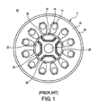
- FIG. 1 shows a schematic cross sectional view of a conventional IPM motor 10 with magnets disposed in the rotor core.
- FIG. 2 is an enlarged view of a portion of the motor in FIG. 1 .
- the motor 10 includes a stator core 11 having a hollow cylindrical ring 20 and a core portion 15 formed inside the ring 20.
- the core portion 15 has slots 12 punched therethrough and coils 14 are wound around the slots 12.
- the motor 10 also includes a cylindrical rotor core 16 disposed on the inner side of the stator core 11, wherein a plurality of holes 18 are formed in the rotor core.
- Each hole 18 corresponds to a pole, extends through in the axial direction, and has a U-shaped cross section.
- Three permanent magnets 26 are inserted in each hole 18.
- Reference numeral 22 represents a magnetio-flux holding portion or center pole section that is located on the radially outward side of the hole 18.
- Numeral 24 represents a bridge that is disposed between the end of a magnet hole 18 and the outer periphery of the rotor 16.
- Reference numeral 28 denotes a rotor-shaft inserting hole.
- the centrifugal force acting on the permanent magnets 26 and the centrifugal force acting on the center pole section 22 are concentrated in the bridges 24 of the rotor core 16. For this reason, the radial width of the bridges 24 must be large enough to maintain the required mechanical strength.
- the ring 23, which is formed of highly rigid nonmagnetic material, provides additional strength for the bridges 24.
- the amount of magnetic flux leakage through the bridges 24 is a compromise with the mechanical strength of the rotor core under the centrifugal forces imparted by rotation.
- FIGS. 3 and 4 show schematic transverse cross sectional diagrams of rotor cores described in the '444 patent.
- the rotor core 34 in FIG. 3 includes a plurality of poles, wherein each pole has three trapezoidal shaped magnet holes 35 and three permanent magnets 36 inserted in the magnet insertion holes 35. Both the holes 35 and permanent magnets 36 have prismatic shapes. Between neighboring holes 35 there are disposed ribs 37 that prevent the centrifugal force acting on the permanent magnets 36 and center pole section 39 from being concentrated in the bridges 38, thereby enhancing the rotational speed limit without increasing the radial width of the bridges 38.
- the multiple magnet insertion holes 35 and ribs 37 increase magnetic flux leakage between neighboring poles and reduce torque production, i.e., a higher rotational speed may be obtained at the expense of torque reduction.
- the rotor core 40 in FIG. 4 includes U-shaped permanent magnet insertion holes 43 and permanent magnets 44 inserted in the holes.
- the rotor core 40 also includes an annular nonmagnetic ring 42 that covers the outer peripheral portion of the rotor core.
- the ring 42 which is formed of highly rigid nonmagnetic material, is used in place of bridges or in addition to the bridges. Because the annular nonmagnetic ring 42 is fitted over the outer peripheral portion of the rotor core 40, the structure is able to resist the breakage of the rotor due to the centrifugal force acting on the magnets 44 and center pole section 46 during operation.
- the magnetic flux leakage from the center pole section 46 is reduced, thereby making it possible to obtain a high magnetic flux density in the center pole section 46.
- the size of the permanent magnets 44 can be made large and the magnetic flux density produced in the center pole section 46 as well as the saliency in the rotor core 40 can increase, the overall torque can be increased.
- the disadvantage of incorporating the nonmagnetic ring 42 is that it significantly increases the manufacturing cost.
- the gap between the rotor core 40 and stator decreases and eddy current loss may increase if the ring 42 is metallic. Thus, there is a need for low cost motors with enhanced rotational speeds, power, and torque densities.
- a permanent magnet rotor includes: a rotor core having a generally cylindrical shape with an outer circumferential surface and a rotational axis; a plurality of magnet insertion holes formed in the rotor core and arranged circumferentially at a preset angular interval about the rotational axis, each hole extending in a direction parallel to the rotational axis and having a cross section of a generally elongated slit; the elongated slit curved concave relative to the circumferential surface and having a radially inward side, a radially outward side, and two ends that are respectively spaced apart from the circumferential surface by two bridges thereby to form a rotor center core section located circumferentially between the bridges and located radially between the radially outward side of the slit and the outer circumferential surface of the rotor core, each of the bridges having thicker and thinner portions that are respectively positioned near the radially inward and outward sides;
- an electrical motor in another embodiment, includes: a stator having a generally hollow cylindrical shape with an inner circumferential surface and including one or more coils coupled to a power source; a rotor core positioned within the inner circumferential surface of the stator and having a generally cylindrical shape with an outer circumferential surface and a rotational axis, the outer circumferential surface being positioned coaxially with respect to the inner surface of the stator in a spaced apart relationship; a plurality of magnet insertion holes formed in the rotor core and arranged circumferentially at a preset angular interval about the rotational axis, each hole extending in a direction parallel to the rotational axis and having a cross section of a generally elongated slit; the elongated slit curved concave relative to the outer circumferential surface and having a radially inward side, a radially outward side, and two ends that are respectively spaced apart from the outer circumferential surface by two bridges, each of the bridges
- a permanent magnet rotor includes: a rotor core having a generally cylindrical shape with an outer circumferential surface and a rotational axis; a plurality of magnet insertion holes formed in the rotor core and arranged circumferentially at a preset angular interval about the rotational axis, each hole extending in a direction parallel to the rotational axis and having a cross section of a generally elongated slit; the elongated slit curved concave relative to the circumferential surface and having a radially inward side, a radially outward side, and two ends that are respectively spaced apart from the circumferential surface by two bridges, each of the bridges having thicker and thinner portions that are respectively positioned near the radially inward and outward sides; and a center magnet and two outer magnets inserted in each of the holes, each of the center and outer magnets having a generally trapezoidal cross section, each of the two outer magnets having a first non-paralle
- FIG. 1 shows a schematic cross sectional view of a conventional IPM motor having permanent magnets disposed in its rotor.
- FIG. 2 is an enlarged view of a portion of the motor in FIG. 1 .
- FIGS. 3 and 4 show schematic cross sectional views of rotors described in prior art.
- FIG. 5 shows a schematic sectional view of a motor in accordance with one embodiment.
- FIG. 6 shows a schematic perspective view of the rotor core in FIG. 5 .
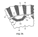
- FIG. 7A shows a schematic partial cross sectional view of the motor in FIG. 6 .
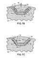
- FIG. 7B shows a schematic partial cross sectional view of the rotor core in FIG. 7A during operation with deflection exaggerated
- FIG. 7C shows a schematic partial cross sectional view of another embodiment of a rotor core.
- FIG. 7D shows a schematic partial cross sectional view of yet another embodiment of a rotor core.
- FIG. 8 shows a schematic cross sectional view of the rotor core in FIG. 6 .
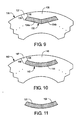
- FIG. 9 shows a schematic partial cross sectional view of yet another embodiment of a rotor core.
- FIG. 10 shows a schematic partial cross sectional view of still another embodiment of a rotor core.
- FIG. 11 shows a schematic cross sectional view of an embodiment of two permanent magnets.
- the preferred embodiments provide various rotor designs, more specifically, various configurations of the permanent magnet insertion holes formed in rotor cores.
- One or more permanent magnets are inserted in each hole that corresponds to a magnetic pole, wherein each hole is designed to relieve the bridges from carrying the full centrifugal load acting on the permanent magnets during operation of the rotor core, thereby reducing mechanical stress in the bridges.
- the reduction in mechanical stress allows the bridge thickness to be reduced and the magnetic flux leakage between adjacent poles to be reduced.
- FIG. 5 shows a sectional view of an interior permanent magnet (IPM) motor, taken along a direction parallel to the rotational axis of rotor, in accordance with one embodiment of the present invention.
- the motor 100 includes a rotor core 104 disposed inside a stator core 102, and a motor output shaft 106 that rotates with the rotor core 104 along the central axis of rotation.
- the shaft 106 is attached to the stator core 102 by means of a bearing 108.
- the stator core 102 has a generally cylindrical shape and includes coils or windings coupled to a power source for providing alternating current for the coils during operation.
- FIG. 6 shows a schematic perspective view of the rotor core 104 in FIG. 5 .
- the rotor core 104 includes a plurality of permanent magnet insertion slits or holes 110 arranged circumferentially at a preset angular interval about the rotational axis of the rotor core and has a generally cylindrical shape
- the rotor core 104 is formed by a single member or by laminating a multiplicity of punched plates, made from material, such as, but not limited to, Fe, SiFe, NiFe, SiFeCo, and SiFeP, or any material classified as an electrical steel, a soft magnetic composite, or any other material with a magnetic permeability greater than air.
- Each hole 110 which corresponds to a magnet pole, has a generally U-shaped cross section and extends through the rotor core 104 in a direction parallel to the rotational axis of the rotor core, thereby forming an elongated hollow shape. It should be apparent to those of ordinary skill in the art that the rotor core 104 may have other suitable numbers of holes 110. Also, it should be apparent that the rotor core 104 may be used in other suitable types of permanent magnet motors.
- FIG. 7A shows a schematic partial cross sectional view of the motor 100 in FIG. 6 , taken along a direction normal to the rotational axis of the rotor core 104.
- three permanent magnets 112a, 112b, 112c are inserted in the hole 110 to form a permanent magnetic pole.
- the three permanent magnets 112 may be replaced by a permanent magnet having the same cross sectional shape as the hole 110.
- Each permanent magnet 112 has a prismatic shape, i.e., each magnet has an elongated shape with a trapezoidal cross section.
- the length of the magnets 112 along the rotational axis of the rotor core 104 is the same as that of the hole 110.
- the cross section of the magnets 112 is dimensioned such that three permanent magnets are fitted in the hole 110, preferably filling the entire space of the hole.
- the stator core 102 includes teeth 114 formed along the inner periphery thereof at a preset angular interval and windings or coils 116 wound around the teeth.
- the coils 116 may be, for instance, three-phase windings, if a three-phase alternating current is allowed to flow through the coils 116.
- the rotor core 104 is caused to rotate by permanent magnetic field torque due to the interaction between the current flowing through the coil 116 and the magnetic flux of the permanent magnets 112. Also, each permanent magnet 112 tends to align itself in the minimum reluctance position relative to the magnetic field generated by the current flowing through the coils 116, thereby generating the reluctance torque that also turns the rotor core 104 with respect to the stator core 102.
- the permanent magnets 112 inserted in the holes 110 change their orientation with respect to the coils 116 during spinning.
- Different shapes such as a V-shape or an arc-shape, may be used as detailed in FIGS. 9-10 .
- the hole 110 is assumed to have a generally U-shape in the following disclosure.
- the rotor core 104 includes bridges 117, which refer to the region between the tips of the U-shaped hole 110 and the outer periphery of the rotor core 104.
- the bridge 117 has a non-uniform radial thickness and includes a minor bridge thickness (equivalently, minor bridge portion or thinner portion) 120 and a major bridge thickness (equivalently, major bridge portion or thicker portion) 122.
- Each U-shaped hole 110 accommodates three permanent magnets 112 and each magnet has a prismatic shape.
- the center pole section 118 which refers to a portion of the rotor core that is located circumferentially between the bridges 117 and located radially between the radially outward surface of the U-shaped hole 110 and outer circumferential surface of rotor core 104, is a region having a high magnetic flux density.
- center pole section is used interchangeably with the term “rotor center core section.”
- the center pole section 118 is connected to the main central portion 119 of the rotor 104 by the bridges 117, thereby forming an integral body of the rotor core.
- the dimension of the U-shaped hole 110 along the outer periphery of the rotor core 104 is determined by the number of magnetic poles in the rotor core 104 as well as the interval between two neighboring teeth 114 of the stator core 102.
- the thickness of the U-shaped hole 110 is determined in conjunction with the material of permanent magnets 112 as well as the rotational speed limit and the magnetic flux density in the center pole section 118.
- the cross section of the magnets 112a-112c are designed such that one magnet makes a tight contact with neighboring permanent magnet(s) in the hole 110 during operation, i.e., one side surface of the center magnet 112b is in contact or would be forced to be in contact with a side surface of the left outer magnet 112a under excitation from a centrifugal or radial force during operation. Likewise, the other side surface of the center magnet 112b is in contact or would be forced in contact with a side surface of the right outer magnet 112c under excitation from a centrifugal force. The centrifugal force acting on the permanent magnets 112a-112c during operation is then transmitted through the permanent magnets to some portion of the bridge between the minor and major bridge portions.
- the U-shaped configuration of the hole 110 allows the force transmitted to the minor bridge portion 120 to be limited to the centrifugal force acting on the center pole section 118 alone.
- the stress in minor bridge portions 120 will be relieved. Absent the force transmission mechanism of FIG. 7A , the centrifugal forces acting on the magnets 112a - 112c would be transferred to the center core section 118 and thereby carried substantially by the minor bridge portions 120.
- the stress in the minor bridge portions 120 are greatly relieved.
- FIG. 7B shows a schematic (not scaled) partial cross sectional view of the rotor core in FIG. 7A during operation.
- the radial deflection of the center pole section 118 is exaggerated in FIG. 7B .
- the center pole section 118 is deformed to bend away from the rotational axis of the rotor 104 by the centrifugal force 125 acting on the center pole section 118, developing an air space or gap 123 between the center pole section and the magnets 112 and thereby separating the radially inward side of the center pole section 118 from the permanent magnets 112 during operation. Due to the gap 123, the centrifugal forces acting on the magnets 112 are not transmitted to the center pole section 118.
- centrifugal forces are transmitted through the outer magnets 112a, 112c, as indicated by arrows 127, so that the stress due to the transmitted centrifugal force is mostly diverted to the major bridge portion 122 or some portion of the bridge between the major and minor bridge portions.
- Transmitting the centrifugal force from the center magnet 112b to the outer magnets 112a, 112c directs the centrifugal force imparted on the magnets 112 away from the center pole section 118, thereby relieving the force transmitted to the minor bridge portion 120.
- the magnets 112 are in tight contact with each other during operation so that the centrifugal force acting on the center magnet 112b is transmitted to the outer magnets 112a, 112c.
- the U-shaped cross sectional geometry of the hole 110 incorporates a way of reducing the mechanical stress in the bridge 117 by transferring the magnet's centrifugal load to the major bridge portion 122. Thus, a ring is not necessary.
- the U-shaped geometry allows the magnets 112 to be in tight contact (or, equivalently locked) with each other within the rotor core during operation without imparting the full centrifugal force to the minor bridge portion 120, thereby reducing the mechanical stress in the minor bridge portion. Reducing the stress in the minor bridge portion 120 allows the minor bridge portion to be made smaller for a given rotor speed rating, thereby lessening the magnetic flux leakage and increasing the output torque of the motor 100.
- a smaller minor bridge portion 120 magnetically saturates with a smaller amount of flux leakage from the permanent magnets 112, preventing further flux leakage from the permanent magnets 112 or the stator windings 116.
- the design feature that limits the force being applied to the center pole section 118 and provides the contacting action between the magnets leads to the benefits described herein.
- the conventional rotor 10 includes both an annular ring 23 and outer peripheral bridges 24 to retain the magnets 26 within a single U-Shaped magnet insertion hole 18.
- the magnets 26 are not constructed in a prismatic shape that would allow transmission of the centrifugal force acting on the magnets 26 to the outer periphery bridges 24 directly. Instead, the magnets 26 have rectangular cross sections, and therefore, the magnets 26 transmit the centrifugal force directly to the center pole section 22 during operation, increasing the mechanical stress in the bridges 24.
- the bridges 24 are preferably of non-uniform thickness needed to complete the necessary geometry to provide the locking action of the magnets within the core.
- the previously referenced patent discloses a rotor core 34 having U-shaped magnet insertion holes 35, wherein each hole corresponds to a pole and is divided with additional bridges or ribs 37 to make multiple magnet insertion holes per pole.
- the embodiment of the rotor core 104 in FIGS. 6-7A has only one hole per pole and multiple magnets 112 are fitted in the hole 110, allowing the permanent magnets 112 to contact each other and to transmit the centrifugal force exerted on the permanent magnets 112 through the permanent magnets.
- the U-shaped magnet insertion hole 110 can be made shallow so that the center pole section 118 has a low mass.
- FIG. 7C shows a schematic partial cross sectional view of another embodiment of a rotor core 160.
- the components of the rotor core 160 are similar to those of the rotor core 104, with the difference that the outer permanent magnets 162a, 162c inserted into a hole 166 have rounded corners on the minor bridge portion sides 172.
- the rounding of the corners generates air spaces or gaps 164 between the magnets 162a, 162c and the minor bridge portions 172 while the magnets 162a, 162c are in contact with the major bridge portions 170. Due to the gaps 164, the centrifugal forces transmitted through the outer magnets 162a, 162c in the directions of arrows 168 are mostly transferred to the major bridge portions 170, thereby relieving the stress in the minor bridge portions 172.
- FIG. 7D shows a schematic partial cross sectional view of yet another embodiment of a rotor core 180.
- the components of the rotor core 180 are similar to those of the rotor core 104, with the difference that there are recesses 184 in the bridges 185 that are open and not filled with the magnets 182a, 182c.
- the portions (or, equivalently, recesses) 184 are most likely air gaps or filled with structural adhesive if the magnets 182a - 182c are inserted with structural adhesive.
- the centrifugal forces transmitted through the outer magnets 182a, 182c in the directions of arrows 188 are mostly transferred to the major bridge portions 190 instead of uniformly across the bridges 185, thereby relieving the stress in the minor bridge portions 192.
- a single magnet having the same cross sectional shape as the hole 110 may be used in place of the three magnets 112.
- the single magnet may have rounded corners to form gaps that are similar to the gaps 164 so that the stress in the minor bridge portions is reduced during operation.
- FIG. 8 shows a schematic cross sectional view of the rotor core 104 in FIG. 6 , taken along a direction normal to the rotational axis of the rotor core.
- polarities of the permanent magnets 112 of adjacent U-shaped holes 110 are arranged to be opposite to each other.
- the three permanent magnets 112 in each hole 110 are arranged such that the center pole section 118 surrounded by the three magnets faces the same polarity of the three permanent magnets. It is noted that twelve poles are shown in FIG. 8 for the purpose of illustration, even though other suitable number of poles may be used without deviating from the spirit of the present teachings.
- FIG. 9 shows a partial cross sectional view of another embodiment of a rotor core suitable for use in the motor 100.
- the rotor core 130 includes a plurality of magnet insertion holes 132 and permanent magnets 134a, 134b inserted in the holes.
- the rotor core 130 is similar to that shown in FIG. 6 , with the differences that the hole 132 has a V-shape in place of a U-shape and that two permanent magnets 134a, 134b are inserted in each hole 132.
- Each of the magnets 134a, 134b has an elongated shape with a trapezoidal cross section.
- a single permanent magnet having the same cross sectional shape as the hole 132 may be used in place of the two magnets 134a, 134b.
- the two permanent magnets 134a, 134b are arranged within the hole 132 such that one magnet tightly contacts (or, equivalently interlocks) the other magnet during operation, i.e., a side surface of the left magnet 134a is in contact or would be forced to be in contact with a side surface of the right magnet 134b under excitation from centrifugal force during operation. This centrifugal force is then mostly transmitted to the major bridge portion 136 of the bridge 137 or some portion of the bridge 137 between the major bridge portion 136 and minor bridge portion 138 of the bridge.
- the V-shaped configuration of the hole 132 allows the force transmitted to the minor bridge portion 138 to be limited to the centrifugal force acting on the center pole section 135 alone. Directing the centrifugal force imparted on the magnets 134a, 134b away from the center pole section 135 relieves the force transmitted to the minor bridge portion 138, reducing the mechanical stress in the minor bridge portion 138.
- FIG. 10 shows a partial cross sectional view of yet another embodiment of a rotor core suitable for use in the motor 100.
- the rotor core 140 is similar to that shown in FIG. 6 , with the differences that the hole 142 has an arc-shape in place of a U-shape and that each hole 142 has one permanent magnet having the same cross sectional shape as the hole 142.
- the radial force acting on the magnet 144 is mostly transmitted to the major bridge portion 146 of the bridge 147 or some portion of the bridge 147 between the major bridge portion 146 and minor bridge portion 148 of the bridge.
- the arc-shaped configuration of the hole 142 allows the force transmitted to minor bridge portion 148 to be limited to the centrifugal force acting on the center pole section 145 alone. Directing the centrifugal force imparted on the magnets 144 away from the center pole section 145 relieves the force transmitted to the minor bridge portion 148, thereby reducing the mechanical stress in the minor bridge portion 148.
- FIG. 11 shows a cross sectional view of another embodiment of two permanent magnets suitable for use in the rotor 140 depicted in FIG. 10 .
- the cross sections of the two permanent magnets 150 are dimensioned such that the magnets 150 fit in the arc-shaped hole 142 in FIG. 10 and tightly contact each other during operation.
- the two magnets 150 have the similar operational mechanism as the permanent magnet 144 in FIG. 10 to reduce the mechanical stress in the minor bridge portion 148.
- the magnets 134 may have rounded corners to form gaps that are similar to the gaps 164 ( FIG. 7C ).
- the single magnet may have rounded corners to form the similar gaps, reducing the mechanical stress in the minor bridge portion 137 during operation.
- the bridges 137 FIG. 9 ), 147 ( FIG. 10 ) may have recesses that are similar to the recesses 184 ( FIG. 7D ).
- the permanent magnets depicted in embodiments of FIGS. 6 - 11 may be glued to the inner surfaces of the holes so that the permanent magnets are secured in place during operation. Conventional glues that can provide the required mechanical strength may be used.
Landscapes
- Engineering & Computer Science (AREA)
- Power Engineering (AREA)
- Permanent Field Magnets Of Synchronous Machinery (AREA)
- Iron Core Of Rotating Electric Machines (AREA)
Abstract
Description
- The present invention relates to an electric motor, and more particularly, to a permanent embedded magnet-type motor.
- In recent years, the drive for energy efficiency and low cost motors has led to development of many types of electric motors and generators for various applications. Among the electric motors, permanent magnet synchronous motors (PMSM) are known to have high power density and efficiency. An interior permanent magnet (IPM) motor, which is a specific type of PMSM and also called permanent magnet reluctance (PMR) motor because of its hybrid ability to produce reluctance torque as well as permanent magnet torque, is one of the most prevalent types. A PMR motor includes a rotor having one or more permanent magnets embedded therein and generates a higher torque than a motor with a surface mounted magnet rotor. It is because the permanent magnets are positioned in the rotor core in such a way as to provide saliency in the magnetic circuit in the rotor core, which produces an additional reluctance torque.
- During operation, each magnet embedded in the rotor core is subject to centrifugal force. In order to retain the magnets within the rotor core under the centrifugal force and also minimize flux leakage to other poles within the rotor core, narrow sections of rotor core material are often retained between the ends of a magnet pole and the outer periphery of the rotor core. These narrow sections are often called "bridges" or bridge areas.
FIG. 1 shows a schematic cross sectional view of aconventional IPM motor 10 with magnets disposed in the rotor core.FIG. 2 is an enlarged view of a portion of the motor inFIG. 1 . As depicted, themotor 10 includes astator core 11 having a hollowcylindrical ring 20 and acore portion 15 formed inside thering 20. Thecore portion 15 hasslots 12 punched therethrough andcoils 14 are wound around theslots 12. Themotor 10 also includes acylindrical rotor core 16 disposed on the inner side of thestator core 11, wherein a plurality ofholes 18 are formed in the rotor core. Eachhole 18 corresponds to a pole, extends through in the axial direction, and has a U-shaped cross section. Threepermanent magnets 26 are inserted in eachhole 18.Reference numeral 22 represents a magnetio-flux holding portion or center pole section that is located on the radially outward side of thehole 18.Numeral 24 represents a bridge that is disposed between the end of amagnet hole 18 and the outer periphery of therotor 16.Reference numeral 28 denotes a rotor-shaft inserting hole. - During operation, the centrifugal force acting on the
permanent magnets 26 and the centrifugal force acting on thecenter pole section 22 are concentrated in thebridges 24 of therotor core 16. For this reason, the radial width of thebridges 24 must be large enough to maintain the required mechanical strength. The ring 23, which is formed of highly rigid nonmagnetic material, provides additional strength for thebridges 24. However, with this arrangement of magnets, the amount of magnetic flux leakage through thebridges 24 is a compromise with the mechanical strength of the rotor core under the centrifugal forces imparted by rotation. Two types of flux leakages occur through thebridge areas 24 and need to be reduced; 1) the flux leakage from thepermanent magnets 26 needs to be reduced so that more of the magnet flux is allowed to link thestator core 11, thereby increasing the magnetic repulsion/attraction torque, 2) flux produced by thecoils 14 and induced in therotor core 16 at the direct-axis rotor position also needs to be minimal in leakage across thebridges 24 so as to increase the reluctance torque produced by themotor 10. A difficulty in theconventional motor 10 may be that thebridge portions 24 need to be made thick to meet the mechanical strength requirement at the expense of a higher flux leakage that leads to a lower torque production. Conversely, thinner bridges lead to a reduction in rotor strength limiting the speed capability of themotor 10. This trade-off relationship between the mechanical strength and magnetic flux leakage has limited the development of higher-speed, higher torque motors. -
U.S. Patent 6,906,444 discloses various types of rotors configured to address the trade-off issue.FIGS. 3 and 4 show schematic transverse cross sectional diagrams of rotor cores described in the '444 patent. Therotor core 34 inFIG. 3 includes a plurality of poles, wherein each pole has three trapezoidalshaped magnet holes 35 and threepermanent magnets 36 inserted in themagnet insertion holes 35. Both theholes 35 andpermanent magnets 36 have prismatic shapes. Between neighboringholes 35 there are disposedribs 37 that prevent the centrifugal force acting on thepermanent magnets 36 andcenter pole section 39 from being concentrated in thebridges 38, thereby enhancing the rotational speed limit without increasing the radial width of thebridges 38. However, the multiplemagnet insertion holes 35 andribs 37 increase magnetic flux leakage between neighboring poles and reduce torque production, i.e., a higher rotational speed may be obtained at the expense of torque reduction. - The
rotor core 40 inFIG. 4 includes U-shaped permanentmagnet insertion holes 43 andpermanent magnets 44 inserted in the holes. Therotor core 40 also includes an annularnonmagnetic ring 42 that covers the outer peripheral portion of the rotor core. Thering 42, which is formed of highly rigid nonmagnetic material, is used in place of bridges or in addition to the bridges. Because the annularnonmagnetic ring 42 is fitted over the outer peripheral portion of therotor core 40, the structure is able to resist the breakage of the rotor due to the centrifugal force acting on themagnets 44 andcenter pole section 46 during operation. Also, the magnetic flux leakage from thecenter pole section 46 is reduced, thereby making it possible to obtain a high magnetic flux density in thecenter pole section 46. As the size of thepermanent magnets 44 can be made large and the magnetic flux density produced in thecenter pole section 46 as well as the saliency in therotor core 40 can increase, the overall torque can be increased. However, the disadvantage of incorporating thenonmagnetic ring 42 is that it significantly increases the manufacturing cost. Also, the gap between therotor core 40 and stator (not shown inFIG. 4 ) decreases and eddy current loss may increase if thering 42 is metallic. Thus, there is a need for low cost motors with enhanced rotational speeds, power, and torque densities. - The above obiect(s) has been achieved by the invention as defined in the claims.
- In one embodiment, a permanent magnet rotor includes: a rotor core having a generally cylindrical shape with an outer circumferential surface and a rotational axis; a plurality of magnet insertion holes formed in the rotor core and arranged circumferentially at a preset angular interval about the rotational axis, each hole extending in a direction parallel to the rotational axis and having a cross section of a generally elongated slit; the elongated slit curved concave relative to the circumferential surface and having a radially inward side, a radially outward side, and two ends that are respectively spaced apart from the circumferential surface by two bridges thereby to form a rotor center core section located circumferentially between the bridges and located radially between the radially outward side of the slit and the outer circumferential surface of the rotor core, each of the bridges having thicker and thinner portions that are respectively positioned near the radially inward and outward sides; and one or more permanent magnets inserted in each of the holes and arranged to transfer the centrifugal forces imparted on the magnets during rotation, directly to portions of the bridges reducing the transfer of the forces to the rotor center core section.
- In another embodiment, an electrical motor includes: a stator having a generally hollow cylindrical shape with an inner circumferential surface and including one or more coils coupled to a power source; a rotor core positioned within the inner circumferential surface of the stator and having a generally cylindrical shape with an outer circumferential surface and a rotational axis, the outer circumferential surface being positioned coaxially with respect to the inner surface of the stator in a spaced apart relationship; a plurality of magnet insertion holes formed in the rotor core and arranged circumferentially at a preset angular interval about the rotational axis, each hole extending in a direction parallel to the rotational axis and having a cross section of a generally elongated slit; the elongated slit curved concave relative to the outer circumferential surface and having a radially inward side, a radially outward side, and two ends that are respectively spaced apart from the outer circumferential surface by two bridges, each of the bridges having thicker and thinner portions that are respectively positioned near the radially inward and outward sides; and one or more permanent magnets inserted in each of the holes and arranged to transfer centrifugal forces acting on the magnets during operation to portions of the bridges. The rotor core rotates along the rotational axis when the power source provides an electrical current to the coils.
- In still another embodiment, a permanent magnet rotor includes: a rotor core having a generally cylindrical shape with an outer circumferential surface and a rotational axis; a plurality of magnet insertion holes formed in the rotor core and arranged circumferentially at a preset angular interval about the rotational axis, each hole extending in a direction parallel to the rotational axis and having a cross section of a generally elongated slit; the elongated slit curved concave relative to the circumferential surface and having a radially inward side, a radially outward side, and two ends that are respectively spaced apart from the circumferential surface by two bridges, each of the bridges having thicker and thinner portions that are respectively positioned near the radially inward and outward sides; and a center magnet and two outer magnets inserted in each of the holes, each of the center and outer magnets having a generally trapezoidal cross section, each of the two outer magnets having a first non-parallel side in contact with a non-parallel side of the center magnet and a second non-parallel side in contact with one of the bridges.
-
FIG. 1 shows a schematic cross sectional view of a conventional IPM motor having permanent magnets disposed in its rotor. -
FIG. 2 is an enlarged view of a portion of the motor inFIG. 1 . -
FIGS. 3 and 4 show schematic cross sectional views of rotors described in prior art. -
FIG. 5 shows a schematic sectional view of a motor in accordance with one embodiment. -
FIG. 6 shows a schematic perspective view of the rotor core inFIG. 5 . -
FIG. 7A shows a schematic partial cross sectional view of the motor inFIG. 6 . -
FIG. 7B shows a schematic partial cross sectional view of the rotor core inFIG. 7A during operation with deflection exaggerated, -
FIG. 7C shows a schematic partial cross sectional view of another embodiment of a rotor core. -
FIG. 7D shows a schematic partial cross sectional view of yet another embodiment of a rotor core. -
FIG. 8 shows a schematic cross sectional view of the rotor core inFIG. 6 . -
FIG. 9 shows a schematic partial cross sectional view of yet another embodiment of a rotor core. -
FIG. 10 shows a schematic partial cross sectional view of still another embodiment of a rotor core. -
FIG. 11 shows a schematic cross sectional view of an embodiment of two permanent magnets. - Broadly, the preferred embodiments provide various rotor designs, more specifically, various configurations of the permanent magnet insertion holes formed in rotor cores. One or more permanent magnets are inserted in each hole that corresponds to a magnetic pole, wherein each hole is designed to relieve the bridges from carrying the full centrifugal load acting on the permanent magnets during operation of the rotor core, thereby reducing mechanical stress in the bridges. The reduction in mechanical stress allows the bridge thickness to be reduced and the magnetic flux leakage between adjacent poles to be reduced.
-
FIG. 5 shows a sectional view of an interior permanent magnet (IPM) motor, taken along a direction parallel to the rotational axis of rotor, in accordance with one embodiment of the present invention. As depicted, themotor 100 includes arotor core 104 disposed inside astator core 102, and amotor output shaft 106 that rotates with therotor core 104 along the central axis of rotation. Theshaft 106 is attached to thestator core 102 by means of abearing 108. Thestator core 102 has a generally cylindrical shape and includes coils or windings coupled to a power source for providing alternating current for the coils during operation. -
FIG. 6 shows a schematic perspective view of therotor core 104 inFIG. 5 . As depicted, therotor core 104 includes a plurality of permanent magnet insertion slits orholes 110 arranged circumferentially at a preset angular interval about the rotational axis of the rotor core and has a generally cylindrical shape, Therotor core 104 is formed by a single member or by laminating a multiplicity of punched plates, made from material, such as, but not limited to, Fe, SiFe, NiFe, SiFeCo, and SiFeP, or any material classified as an electrical steel, a soft magnetic composite, or any other material with a magnetic permeability greater than air. Eachhole 110, which corresponds to a magnet pole, has a generally U-shaped cross section and extends through therotor core 104 in a direction parallel to the rotational axis of the rotor core, thereby forming an elongated hollow shape. It should be apparent to those of ordinary skill in the art that therotor core 104 may have other suitable numbers ofholes 110. Also, it should be apparent that therotor core 104 may be used in other suitable types of permanent magnet motors. -
FIG. 7A shows a schematic partial cross sectional view of themotor 100 inFIG. 6 , taken along a direction normal to the rotational axis of therotor core 104. As depicted, threepermanent magnets hole 110 to form a permanent magnetic pole. Alternatively, the threepermanent magnets 112 may be replaced by a permanent magnet having the same cross sectional shape as thehole 110. Eachpermanent magnet 112 has a prismatic shape, i.e., each magnet has an elongated shape with a trapezoidal cross section. The length of themagnets 112 along the rotational axis of therotor core 104 is the same as that of thehole 110. The cross section of themagnets 112 is dimensioned such that three permanent magnets are fitted in thehole 110, preferably filling the entire space of the hole. - The
stator core 102 includesteeth 114 formed along the inner periphery thereof at a preset angular interval and windings or coils 116 wound around the teeth. Thecoils 116 may be, for instance, three-phase windings, if a three-phase alternating current is allowed to flow through thecoils 116. Therotor core 104 is caused to rotate by permanent magnetic field torque due to the interaction between the current flowing through thecoil 116 and the magnetic flux of thepermanent magnets 112. Also, eachpermanent magnet 112 tends to align itself in the minimum reluctance position relative to the magnetic field generated by the current flowing through thecoils 116, thereby generating the reluctance torque that also turns therotor core 104 with respect to thestator core 102. - The
permanent magnets 112 inserted in theholes 110 change their orientation with respect to thecoils 116 during spinning. Different shapes, such as a V-shape or an arc-shape, may be used as detailed inFIGS. 9-10 . For the purpose of illustration, thehole 110 is assumed to have a generally U-shape in the following disclosure. - The
rotor core 104 includesbridges 117, which refer to the region between the tips of theU-shaped hole 110 and the outer periphery of therotor core 104. Thebridge 117 has a non-uniform radial thickness and includes a minor bridge thickness (equivalently, minor bridge portion or thinner portion) 120 and a major bridge thickness (equivalently, major bridge portion or thicker portion) 122. EachU-shaped hole 110 accommodates threepermanent magnets 112 and each magnet has a prismatic shape. Thecenter pole section 118, which refers to a portion of the rotor core that is located circumferentially between thebridges 117 and located radially between the radially outward surface of theU-shaped hole 110 and outer circumferential surface ofrotor core 104, is a region having a high magnetic flux density. Hereinafter, the term "center pole section "is used interchangeably with the term " rotor center core section." - The
center pole section 118 is connected to the maincentral portion 119 of therotor 104 by thebridges 117, thereby forming an integral body of the rotor core. The dimension of theU-shaped hole 110 along the outer periphery of therotor core 104 is determined by the number of magnetic poles in therotor core 104 as well as the interval between two neighboringteeth 114 of thestator core 102. As the centrifugal force acting on thepermanent magnets 112 is transferred to thebridges 117 and the centrifugal force is proportional to the mass of thepermanent magnets 112 as well as the rotational speed squared, the thickness of theU-shaped hole 110 is determined in conjunction with the material ofpermanent magnets 112 as well as the rotational speed limit and the magnetic flux density in thecenter pole section 118. - The cross section of the
magnets 112a-112c are designed such that one magnet makes a tight contact with neighboring permanent magnet(s) in thehole 110 during operation, i.e., one side surface of thecenter magnet 112b is in contact or would be forced to be in contact with a side surface of the leftouter magnet 112a under excitation from a centrifugal or radial force during operation. Likewise, the other side surface of thecenter magnet 112b is in contact or would be forced in contact with a side surface of the rightouter magnet 112c under excitation from a centrifugal force. The centrifugal force acting on thepermanent magnets 112a-112c during operation is then transmitted through the permanent magnets to some portion of the bridge between the minor and major bridge portions. Thus, the U-shaped configuration of thehole 110 allows the force transmitted to theminor bridge portion 120 to be limited to the centrifugal force acting on thecenter pole section 118 alone. By reducing or relieving forces transferred to the rotorcenter core section 118, the stress inminor bridge portions 120 will be relieved. Absent the force transmission mechanism ofFIG. 7A , the centrifugal forces acting on themagnets 112a - 112c would be transferred to thecenter core section 118 and thereby carried substantially by theminor bridge portions 120. By transferring some of the forces tobridges 117, the stress in theminor bridge portions 120 are greatly relieved. -
FIG. 7B shows a schematic (not scaled) partial cross sectional view of the rotor core inFIG. 7A during operation. For the purpose of illustration, the radial deflection of thecenter pole section 118 is exaggerated inFIG. 7B . As depicted, thecenter pole section 118 is deformed to bend away from the rotational axis of therotor 104 by thecentrifugal force 125 acting on thecenter pole section 118, developing an air space orgap 123 between the center pole section and themagnets 112 and thereby separating the radially inward side of thecenter pole section 118 from thepermanent magnets 112 during operation. Due to thegap 123, the centrifugal forces acting on themagnets 112 are not transmitted to thecenter pole section 118. Instead, the centrifugal forces are transmitted through theouter magnets arrows 127, so that the stress due to the transmitted centrifugal force is mostly diverted to themajor bridge portion 122 or some portion of the bridge between the major and minor bridge portions. - Transmitting the centrifugal force from the
center magnet 112b to theouter magnets magnets 112 away from thecenter pole section 118, thereby relieving the force transmitted to theminor bridge portion 120. Themagnets 112 are in tight contact with each other during operation so that the centrifugal force acting on thecenter magnet 112b is transmitted to theouter magnets FIG. 4 ) that requires anadditional ring 42 to strengthen thebridges 24, the U-shaped cross sectional geometry of thehole 110 incorporates a way of reducing the mechanical stress in thebridge 117 by transferring the magnet's centrifugal load to themajor bridge portion 122. Thus, a ring is not necessary. - The U-shaped geometry allows the
magnets 112 to be in tight contact (or, equivalently locked) with each other within the rotor core during operation without imparting the full centrifugal force to theminor bridge portion 120, thereby reducing the mechanical stress in the minor bridge portion. Reducing the stress in theminor bridge portion 120 allows the minor bridge portion to be made smaller for a given rotor speed rating, thereby lessening the magnetic flux leakage and increasing the output torque of themotor 100. A smallerminor bridge portion 120 magnetically saturates with a smaller amount of flux leakage from thepermanent magnets 112, preventing further flux leakage from thepermanent magnets 112 or thestator windings 116. The design feature that limits the force being applied to thecenter pole section 118 and provides the contacting action between the magnets leads to the benefits described herein. - As discussed with reference to
FIG. 1 , theconventional rotor 10 includes both an annular ring 23 and outerperipheral bridges 24 to retain themagnets 26 within a single U-Shapedmagnet insertion hole 18. However, as depicted inFIG. 1 , themagnets 26 are not constructed in a prismatic shape that would allow transmission of the centrifugal force acting on themagnets 26 to the outer periphery bridges 24 directly. Instead, themagnets 26 have rectangular cross sections, and therefore, themagnets 26 transmit the centrifugal force directly to thecenter pole section 22 during operation, increasing the mechanical stress in thebridges 24. In addition, thebridges 24 are preferably of non-uniform thickness needed to complete the necessary geometry to provide the locking action of the magnets within the core. - As discussed in conjunction with
FIG. 3 , the previously referenced patent discloses arotor core 34 having U-shaped magnet insertion holes 35, wherein each hole corresponds to a pole and is divided with additional bridges orribs 37 to make multiple magnet insertion holes per pole. In contrast, the embodiment of therotor core 104 inFIGS. 6-7A has only one hole per pole andmultiple magnets 112 are fitted in thehole 110, allowing thepermanent magnets 112 to contact each other and to transmit the centrifugal force exerted on thepermanent magnets 112 through the permanent magnets. The U-shapedmagnet insertion hole 110 can be made shallow so that thecenter pole section 118 has a low mass. By use of the hole configuration inFIGS. 6-7A , it is possible to obtain large torque while themotor 100 can operate at higher speeds. -
FIG. 7C shows a schematic partial cross sectional view of another embodiment of arotor core 160. The components of therotor core 160 are similar to those of therotor core 104, with the difference that the outerpermanent magnets hole 166 have rounded corners on the minor bridge portion sides 172. The rounding of the corners generates air spaces orgaps 164 between themagnets magnets major bridge portions 170. Due to thegaps 164, the centrifugal forces transmitted through theouter magnets arrows 168 are mostly transferred to themajor bridge portions 170, thereby relieving the stress in the minor bridge portions 172. -
FIG. 7D shows a schematic partial cross sectional view of yet another embodiment of arotor core 180. The components of therotor core 180 are similar to those of therotor core 104, with the difference that there arerecesses 184 in thebridges 185 that are open and not filled with themagnets magnets 182a - 182c are inserted with structural adhesive. In this embodiment, the centrifugal forces transmitted through theouter magnets arrows 188 are mostly transferred to themajor bridge portions 190 instead of uniformly across thebridges 185, thereby relieving the stress in theminor bridge portions 192. - A discussed above, a single magnet having the same cross sectional shape as the
hole 110 may be used in place of the threemagnets 112. In this case, the single magnet may have rounded corners to form gaps that are similar to thegaps 164 so that the stress in the minor bridge portions is reduced during operation. -
FIG. 8 shows a schematic cross sectional view of therotor core 104 inFIG. 6 , taken along a direction normal to the rotational axis of the rotor core. As depicted, polarities of thepermanent magnets 112 of adjacentU-shaped holes 110 are arranged to be opposite to each other. The threepermanent magnets 112 in eachhole 110 are arranged such that thecenter pole section 118 surrounded by the three magnets faces the same polarity of the three permanent magnets. It is noted that twelve poles are shown inFIG. 8 for the purpose of illustration, even though other suitable number of poles may be used without deviating from the spirit of the present teachings. -
FIG. 9 shows a partial cross sectional view of another embodiment of a rotor core suitable for use in themotor 100. As depicted, therotor core 130 includes a plurality of magnet insertion holes 132 andpermanent magnets rotor core 130 is similar to that shown inFIG. 6 , with the differences that thehole 132 has a V-shape in place of a U-shape and that twopermanent magnets hole 132. Each of themagnets hole 132 may be used in place of the twomagnets - The two
permanent magnets hole 132 such that one magnet tightly contacts (or, equivalently interlocks) the other magnet during operation, i.e., a side surface of theleft magnet 134a is in contact or would be forced to be in contact with a side surface of theright magnet 134b under excitation from centrifugal force during operation. This centrifugal force is then mostly transmitted to themajor bridge portion 136 of thebridge 137 or some portion of thebridge 137 between themajor bridge portion 136 andminor bridge portion 138 of the bridge. Thus, as in the cases ofFIGS, 7A and7C , the V-shaped configuration of thehole 132 allows the force transmitted to theminor bridge portion 138 to be limited to the centrifugal force acting on thecenter pole section 135 alone. Directing the centrifugal force imparted on themagnets center pole section 135 relieves the force transmitted to theminor bridge portion 138, reducing the mechanical stress in theminor bridge portion 138. -
FIG. 10 shows a partial cross sectional view of yet another embodiment of a rotor core suitable for use in themotor 100. Therotor core 140 is similar to that shown inFIG. 6 , with the differences that thehole 142 has an arc-shape in place of a U-shape and that eachhole 142 has one permanent magnet having the same cross sectional shape as thehole 142. During operation, the radial force acting on the magnet 144 is mostly transmitted to themajor bridge portion 146 of thebridge 147 or some portion of thebridge 147 between themajor bridge portion 146 andminor bridge portion 148 of the bridge. Thus, as in the cases ofFIGS. 7A and7C , the arc-shaped configuration of thehole 142 allows the force transmitted tominor bridge portion 148 to be limited to the centrifugal force acting on thecenter pole section 145 alone. Directing the centrifugal force imparted on the magnets 144 away from thecenter pole section 145 relieves the force transmitted to theminor bridge portion 148, thereby reducing the mechanical stress in theminor bridge portion 148. -
FIG. 11 shows a cross sectional view of another embodiment of two permanent magnets suitable for use in therotor 140 depicted inFIG. 10 . The cross sections of the twopermanent magnets 150 are dimensioned such that themagnets 150 fit in the arc-shapedhole 142 inFIG. 10 and tightly contact each other during operation. The twomagnets 150 have the similar operational mechanism as the permanent magnet 144 inFIG. 10 to reduce the mechanical stress in theminor bridge portion 148. - It is noted that the magnets 134 (
FIG. 9 ), 144 (FIG. 10 ), and 150 (FIG. 11 ) may have rounded corners to form gaps that are similar to the gaps 164 (FIG. 7C ). Also, in the case where a single magnet is used in place of the two magnets 134 inFIG. 9 , the single magnet may have rounded corners to form the similar gaps, reducing the mechanical stress in theminor bridge portion 137 during operation. Alternatively, the bridges 137 (FIG. 9 ), 147 (FIG. 10 ) may have recesses that are similar to the recesses 184 (FIG. 7D ). - It is also noted that the permanent magnets depicted in embodiments of
FIGS. 6 - 11 may be glued to the inner surfaces of the holes so that the permanent magnets are secured in place during operation. Conventional glues that can provide the required mechanical strength may be used. - While the invention has been described in detail with reference to specific embodiments thereof, it will be apparent to those skilled in the art that various changes and modifications can be made, and equivalents employed, without departing from the scope of the appended claims.
Claims (30)
- A permanent magnet rotor, comprising:a rotor core having a generally cylindrical shape with an outer circumferential surface and a rotational axis;a plurality of magnet insertion holes formed in the rotor core and arranged circumferentially at a preset angular interval about the rotational axis, each hole extending in a direction parallel to the rotational axis and having a cross section of a generally elongated slit;at least one, such as all of the elongated slit curved concave relative to the circumferential surface and having a radially inward side, a radially outward side, and two ends that are respectively spaced apart from the circumferential surface by two bridges thereby to form a rotor center core section located circumferentially between the bridges and located radially between the radially outward side of the slit and the outer circumferential surface of the rotor core, each of the bridges having a thicker portion and a thinner portion that are respectively positioned near the radially inward and outward sides; andone or more permanent magnets inserted in each of the holes;wherein, if there are more than one permanent magnet in each hole, the magnets in each hole are arranged such that each of the magnets is in direct contact with an adjacent magnet so that centrifugal forces imparted on a center portion of the magnets is transferred through outer portions of the magnets to the bridges.
- The permanent magnet rotor as recited in claim 1, wherein each of the elongated slits has a generally U-shape, a V-shape, or an arc-shape.
- The permanent magnet rotor as recited in any one of claims 1 and 2, wherein at least one, such as all of the elongated slit has a U-shape and three permanent magnets are inserted in each of the holes and interlock each other during rotation.
- The permanent magnet rotor as recited in any one of claims 1 and 2, wherein at least one, such as all of the elongated slit has a V-shape and two permanent magnets are inserted in each of the holes and interlock each other during rotation.
- The permanent magnet rotor as recited in any one of the preceding claims, wherein each of the permanent magnets has a trapezoidal cross section.
- The permanent magnet rotor as recited in any one of claims 1 and 2, wherein the elongated slit has an arc-shape and one permanent magnet is inserted in each of the holes.
- The permanent magnet rotor as recited in claim 6, wherein each of the permanent magnets has a curve slit-shaped cross section.
- The permanent magnet rotor as recited in any one of the preceding claims, wherein the rotor core is formed of a single body.
- The permanent magnet rotor as recited in any one of the preceding claims, wherein the rotor core includes a plurality of plates stacked along the rotational axis, each of the plate being punched to form the elongated slit.
- The permanent magnet rotor as recited in any one of the preceding claims, wherein the rotor core is made from solid soft magnetic composite material.
- The permanent magnet rotor as recited in any one of the preceding claims, wherein the rotor core material is selected from the group consisting of Fe, SiFe, NiFe, SiFeCo, and SiFeP, or any material classified as an electrical steel, a soft magnetic composite, or any other material with a magnetic permeability greater than air.
- The permanent magnet rotor as recited in any one of the preceding claims, wherein the rotor core material is any material classified as an electrical steel, a soft magnetic composite, or any other material with a magnetic permeability greater than air.
- The permanent magnet rotor as recited in any one of the preceding claims, wherein the permanent magnets have rounded corners on the sides of the thinner portions thereby to form gaps between the permanent magnets and the thinner portions.
- The permanent magnet rotor as recited in any one of the preceding claims, wherein the bridges have recesses on the sides of the thinner portions thereby to form gaps between the permanent magnets and the thinner portions.
- The permanent magnet rotor as recited in any one of claims 13 and 14, wherein the gaps are filled with air or structural adhesive.
- The permanent magnet rotor as recited in any one of the preceding claims, wherein the permanent magnets are arranged to prevent a contact between the permanent magnets and the radially outward side of the elongated slit during rotation.
- The permanent magnet rotor as recited in any one of the preceding claims, wherein the one or more permanent magnets are attached to a corresponding one of the holes preferably by glue.
- An electrical motor, optionally comprising a permanent magnet rotor as recited in any one of the preceding claims, said electrical motor comprising:a stator having a generally hollow cylindrical shape with an inner circumferential surface and including one or more coils coupled to a power source;a rotor core positioned within the inner circumferential surface of the stator and having a generally cylindrical shape with an outer circumferential surface and a rotational axis, the outer circumferential surface being positioned coaxially with respect to the inner surface of the stator in a spaced apart relationship;a plurality of magnet insertion holes formed in the rotor core and arranged circumferentially at a preset angular interval about the rotational axis, each hole extending in a direction parallel to the rotational axis and having a cross section of a generally elongated slit;at least one, such as all of the elongated slit curved concave relative to the outer circumferential surface and having a radially inward side, a radially outward side, and two ends that are respectively spaced apart from the outer circumferential surface by two bridges, each of the bridges having a thicker portion and a thinner portion that are respectively positioned near the radially inward and outward sides; andone or more permanent magnets inserted in each of the holes and arranged to transfer a centrifugal force from a center portion of the permanent magnets to portions of the bridges,wherein the rotor core rotates along the rotational axis when the power source provides an electrical current to the coils.
- The electrical motor as recited in claim 18, wherein the motor is a permanent magnet reluctance (PMR) motor.
- A permanent magnet rotor optionally as recited in any one of claims 1-17, said permanent magnet rotor comprising:a rotor core having a generally cylindrical shape with an outer circumferential surface and a rotational axis;a plurality of magnet insertion holes formed in the rotor core and arranged circumferentially at a preset angular interval about the rotational axis, each hole extending in a direction parallel to the rotational axis and having a cross section of a generally elongated slit;at least one, such as all of the elongated slit curved concave relative to the circumferential surface and having a radially inward side, a radially outward side, and two ends that are respectively spaced apart from the circumferential surface by two bridges, each of the bridges having a thicker portion and a thinner portion that are respectively positioned near the radially inward and outward sides; anda center magnet and two outer magnets inserted in each of the holes, each of the center and outer magnets having a generally trapezoidal cross section, each of the two outer magnets having a first non-parallel side in contact with a non-parallel side of the center magnet and a second non-parallel side in contact with one of the bridges.
- The permanent magnet rotor as recited in claim 20, wherein the rotor core is formed of a single body.
- The permanent magnet rotor as recited in any one of claims 20 and 21, wherein the rotor core includes a plurality of plates stacked along the rotational axis, each of the plates being punched to form the elongated slits.
- The permanent magnet rotor as recited in any one of claims 20-22, wherein the rotor core is made of material selected from the group consisting of Fe, SiFe, SiFeCo, and SiFeP.
- The permanent magnet rotor as recited in any one of claims 20-23, wherein the outer magnets have rounded corners on the sides of the thinner portions thereby to form gaps between the outer magnets and the thinner portions.
- The permanent magnet rotor as recited in any one of claims 20-24, wherein the bridges have recesses on the sides of the thinner portions thereby to form gaps between the permanent magnets and the thinner portions.
- The permanent magnet rotor as recited in any one of claims 24 and 25, wherein the gaps are filled with air or structural adhesive.
- A method of operating a rotor according to any one of claims 1-17 and 20-26, said method comprising:mounting the rotor within a stator operative to impart a rotational force on the rotor upon receipt of electrical power;providing electrical power to the stator to cause the rotor to rotate with respect to the rotational axis and thereby to impart centrifugal force on the center magnet; andtransmitting the centrifugal force through the outer magnets to portions of the bridges.
- The method as recited in claim 27, wherein the outer magnets have rounded corners on the sides of the thinner portions thereby to form gaps between the outer magnets and the thinner portions.
- The method as recited in any one of claims 27 and 28, wherein the rotor core includes a plurality of plates stacked along the rotational axis, each of the plates being punched to form the elongated slits.
- The method as recited in any one of claims 27, 28 and 29, wherein the rotor core is formed of solid soft magnetic composite material.
Applications Claiming Priority (1)
| Application Number | Priority Date | Filing Date | Title |
|---|---|---|---|
| US11/746,125 US7598645B2 (en) | 2007-05-09 | 2007-05-09 | Stress distributing permanent magnet rotor geometry for electric machines |
Publications (3)
| Publication Number | Publication Date |
|---|---|
| EP1990895A2 true EP1990895A2 (en) | 2008-11-12 |
| EP1990895A3 EP1990895A3 (en) | 2016-04-06 |
| EP1990895B1 EP1990895B1 (en) | 2022-07-13 |
Family
ID=39712038
Family Applications (1)
| Application Number | Title | Priority Date | Filing Date |
|---|---|---|---|
| EP07024336.5A Active EP1990895B1 (en) | 2007-05-09 | 2007-12-14 | Stress distributing permanent magnet rotor geometry for electric machines |
Country Status (3)
| Country | Link |
|---|---|
| US (1) | US7598645B2 (en) |
| EP (1) | EP1990895B1 (en) |
| CA (1) | CA2615115C (en) |
Cited By (7)
| Publication number | Priority date | Publication date | Assignee | Title |
|---|---|---|---|---|
| DE102010010434A1 (en) | 2010-02-26 | 2011-09-01 | Dr. Ing. H.C. F. Porsche Aktiengesellschaft | Rotor for electric machine i.e. permanent magnet-excited electric machine, has pair of V-shaped recesses provided in such manner that curved outer contours of loaf magnets runs parallel to external periphery of rotor body |
| WO2011122996A1 (en) * | 2010-03-30 | 2011-10-06 | Volvo Technology Corporation | Rotor of an electric machine with embedded permanent magnets and electric machine |
| EP2741399A4 (en) * | 2011-08-05 | 2016-01-06 | Gree Electric Appliances Inc | Motor rotor and motor having same |
| US9246363B2 (en) | 2010-05-20 | 2016-01-26 | Nidec Sr Drives, Ltd | Reducing stress in electric-machine rotors by optimizing holes |
| CN106849417A (en) * | 2015-09-23 | 2017-06-13 | 西门子公司 | Motor with the highly stable rotor of revolution |
| CN111030339A (en) * | 2019-12-16 | 2020-04-17 | 珠海格力电器股份有限公司 | Electric motor rotor and alternating-pole electric motor |
| DE102024112536A1 (en) | 2024-05-03 | 2025-11-06 | Dr. Ing. H.C. F. Porsche Aktiengesellschaft | Rotor of an electric machine designed as a permanent magnet synchronous machine, electric machine and motor vehicle |
Families Citing this family (38)
| Publication number | Priority date | Publication date | Assignee | Title |
|---|---|---|---|---|
| JP5085071B2 (en) * | 2006-08-11 | 2012-11-28 | 株式会社東芝 | Permanent magnet type rotating electrical machine rotor |
| CN101978576A (en) * | 2008-03-19 | 2011-02-16 | 三洋电机株式会社 | Permanent magnet synchronization motor |
| JP5159577B2 (en) * | 2008-11-19 | 2013-03-06 | 株式会社東芝 | Permanent magnet rotating electric machine |
| US8754560B2 (en) | 2009-11-25 | 2014-06-17 | Uqm Technologies, Inc. | Rotor for a permanent magnet electric machine |
| US9577503B2 (en) * | 2010-05-03 | 2017-02-21 | The Board Of Regents Of The University Of Texas System | Rotating machines using trapped field magnets and related methods |
| CA2828527C (en) * | 2011-02-28 | 2016-09-13 | Danfoss Power Solutuins (Us) Company | Brushless pm machine construction enabling low coercivity magnets |
| KR101243491B1 (en) * | 2011-04-13 | 2013-03-13 | 뉴모텍(주) | Rotor for Motor |
| CN102769365A (en) * | 2011-07-28 | 2012-11-07 | 珠海格力电器股份有限公司 | Permanent magnet synchronous motor |
| CN102780291A (en) * | 2011-08-05 | 2012-11-14 | 珠海格力电器股份有限公司 | Motor rotor and motor with same |
| CN104321952B (en) * | 2012-05-22 | 2017-07-28 | 三菱电机株式会社 | Permanent magnet embedded rotating electrical machine |
| JP2013255326A (en) * | 2012-06-06 | 2013-12-19 | Hitachi Appliances Inc | Permanent magnet synchronous machine |
| JP5901436B2 (en) * | 2012-06-08 | 2016-04-13 | 日立アプライアンス株式会社 | Permanent magnet synchronous machine |
| WO2014050154A1 (en) * | 2012-09-28 | 2014-04-03 | ダイキン工業株式会社 | Rotor and rotary electric machine |
| CN104685763B (en) * | 2012-09-29 | 2018-07-03 | 艾默生电气公司 | Rotor and associated electric machine and compressor with segmented magnet construction |
| JP6002619B2 (en) * | 2013-04-10 | 2016-10-05 | 株式会社日立産機システム | Permanent magnet synchronous machine and compressor using the same |
| US9641054B2 (en) | 2013-05-17 | 2017-05-02 | General Electric Company | Segmented magnet component for electric machine and method of assembly |
| US9985485B2 (en) * | 2014-04-01 | 2018-05-29 | GM Global Technology Operations LLC | Magnet insert design for rotor lamination |
| US10439456B2 (en) * | 2016-04-25 | 2019-10-08 | General Electric Company | Sleeve rotor synchronous reluctance electric machine |
| FR3067880B1 (en) * | 2017-06-15 | 2020-07-17 | Moteurs Leroy-Somer | ROTATING ELECTRIC MACHINE |
| TWM576750U (en) | 2017-07-25 | 2019-04-11 | 美商米沃奇電子工具公司 | Electrical composition, electric device system, battery pack, electric motor, motor assembly and electric motor assembly |
| CN107394920A (en) * | 2017-08-01 | 2017-11-24 | 珠海格力节能环保制冷技术研究中心有限公司 | Rotor and motor |
| IT201700100814A1 (en) * | 2017-09-08 | 2019-03-08 | S M E S P A | Procedure for the assembly of a rotor of a synchronous motor with variable reluctance and this rotor |
| CN108768015B (en) * | 2018-07-20 | 2020-04-17 | 珠海格力电器股份有限公司 | Rotor assembly and motor |
| CN216398138U (en) | 2019-02-18 | 2022-04-29 | 米沃奇电动工具公司 | impact tool |
| JP7404653B2 (en) * | 2019-05-17 | 2023-12-26 | Tdk株式会社 | rotating electric machine |
| KR102853097B1 (en) | 2019-10-25 | 2025-08-29 | 자코비 모터스 엘엘씨 | Magnetization and control method of variable flux memory motor |
| CN113098166B (en) * | 2020-01-09 | 2022-11-04 | 蜂巢传动系统(江苏)有限公司保定研发分公司 | Rotor punching sheet and rotor iron core |
| US11996739B2 (en) * | 2020-01-09 | 2024-05-28 | Jacobi Motors LLC | Curved magnets for a variable-flux memory motor |
| US11710994B2 (en) * | 2020-02-25 | 2023-07-25 | Tdk Corporation | Rotating electrical machine |
| US11936256B2 (en) | 2020-04-24 | 2024-03-19 | Jacobi Motors, Llc | Flux-mnemonic permanent magnet synchronous machine and magnetizing a flux-mnemonic permanent magnet synchronous machine |
| CN116526713B (en) * | 2022-01-20 | 2026-07-07 | 芜湖美的厨卫电器制造有限公司 | Rotor assembly and motor |
| DE102022106874A1 (en) * | 2022-03-23 | 2023-09-28 | Borgwarner Inc. | Reluctance machine |
| DE102022208504A1 (en) * | 2022-08-16 | 2024-02-22 | Rolls-Royce Deutschland Ltd & Co Kg | Rotor for an electrical machine of an aircraft |
| US12620920B2 (en) | 2022-10-26 | 2026-05-05 | Jacobi Motors, Llc | System and method for shifting operation modes of variable flux memory motors |
| CN115882633A (en) * | 2022-12-05 | 2023-03-31 | 东风本田发动机有限公司 | Rotor punching sheet, motor rotor, motor and manufacturing process of rotor punching sheet |
| JP7903414B2 (en) * | 2023-01-31 | 2026-08-12 | マツダ株式会社 | Rotor structure |
| US12558980B2 (en) | 2023-11-09 | 2026-02-24 | Jacobi Motors, Llc | Integrated variable flux memory motor charger |
| US12614998B2 (en) | 2024-03-04 | 2026-04-28 | Jacobi Motors, Llc | System for multi-variable flux memory motor configuration |
Citations (1)
| Publication number | Priority date | Publication date | Assignee | Title |
|---|---|---|---|---|
| US6906444B2 (en) | 2001-07-10 | 2005-06-14 | Teijin Seiki Co., Ltd. | Permanent magnet motor |
Family Cites Families (21)
| Publication number | Priority date | Publication date | Assignee | Title |
|---|---|---|---|---|
| US4327302A (en) * | 1979-09-21 | 1982-04-27 | General Electric Company | Electronically commutated motor, stationary and rotatable assemblies therefore, and lamination |
| US4570333A (en) * | 1983-10-28 | 1986-02-18 | General Electric Company | Method of making a permanent magnet rotor |
| US5191256A (en) * | 1989-12-15 | 1993-03-02 | American Motion Systems | Interior magnet rotary machine |
| US5510662A (en) | 1993-05-26 | 1996-04-23 | Kabushiki Kaisha Toshiba | Permanent magnet motor |
| EP0746079B1 (en) * | 1995-05-31 | 2003-08-13 | Matsushita Electric Industrial Co., Ltd. | Motor with built-in permanent magnets |
| JPH09298852A (en) * | 1996-04-30 | 1997-11-18 | Aichi Emerson Electric Co Ltd | Brushless DC motor |
| JP3818340B2 (en) * | 1997-09-26 | 2006-09-06 | 株式会社富士通ゼネラル | Permanent magnet motor |
| JP4089072B2 (en) * | 1998-10-23 | 2008-05-21 | 三菱電機株式会社 | Permanent magnet embedded motor |
| JP2001314052A (en) * | 2000-02-25 | 2001-11-09 | Nissan Motor Co Ltd | Rotor structure of synchronous motor |
| JP2001251825A (en) * | 2000-03-01 | 2001-09-14 | Hitachi Ltd | Permanent magnet synchronous motor and air conditioner using the same |
| JP2002078259A (en) * | 2000-08-31 | 2002-03-15 | Yamaha Motor Co Ltd | Permanent magnet rotor |
| JP3616338B2 (en) * | 2001-01-24 | 2005-02-02 | アイチエレック株式会社 | Electric motor rotor |
| CN1579043B (en) | 2002-03-29 | 2010-05-05 | 松下电器产业株式会社 | Motor |
| JP2004104962A (en) * | 2002-09-12 | 2004-04-02 | Toshiba Industrial Products Manufacturing Corp | Permanent magnet type reluctance type rotating electric machine |
| DE10318624A1 (en) * | 2003-04-24 | 2004-11-25 | Minebea Co., Ltd. | Rotor body for an electric motor |
| EP1471621A3 (en) * | 2003-04-24 | 2005-12-14 | Minebea Co., Ltd. | Rotor element for an electrical motor |
| US20040251763A1 (en) | 2003-06-13 | 2004-12-16 | Matsushita Electric Industrial Co., Ltd. | Motor |
| US7981359B2 (en) | 2004-04-06 | 2011-07-19 | Hitachi Metals, Ltd. | Rotor and process for manufacturing the same |
| JP2006325348A (en) * | 2005-05-19 | 2006-11-30 | Nidec Shibaura Corp | Rotor |
| JP2007097387A (en) * | 2005-08-31 | 2007-04-12 | Toshiba Corp | Rotating electric machine |
| JP4815967B2 (en) * | 2005-09-21 | 2011-11-16 | トヨタ自動車株式会社 | Permanent magnet rotating electric machine |
-
2007
- 2007-05-09 US US11/746,125 patent/US7598645B2/en active Active
- 2007-12-14 EP EP07024336.5A patent/EP1990895B1/en active Active
- 2007-12-17 CA CA2615115A patent/CA2615115C/en active Active
Patent Citations (1)
| Publication number | Priority date | Publication date | Assignee | Title |
|---|---|---|---|---|
| US6906444B2 (en) | 2001-07-10 | 2005-06-14 | Teijin Seiki Co., Ltd. | Permanent magnet motor |
Cited By (9)
| Publication number | Priority date | Publication date | Assignee | Title |
|---|---|---|---|---|
| DE102010010434A1 (en) | 2010-02-26 | 2011-09-01 | Dr. Ing. H.C. F. Porsche Aktiengesellschaft | Rotor for electric machine i.e. permanent magnet-excited electric machine, has pair of V-shaped recesses provided in such manner that curved outer contours of loaf magnets runs parallel to external periphery of rotor body |
| WO2011122996A1 (en) * | 2010-03-30 | 2011-10-06 | Volvo Technology Corporation | Rotor of an electric machine with embedded permanent magnets and electric machine |
| US8896175B2 (en) | 2010-03-30 | 2014-11-25 | Volvo Technology Corporation | Rotor of an electric machine with embedded permanent magnets and electric machine |
| EP2553792A4 (en) * | 2010-03-30 | 2017-11-01 | Volvo Technology Corporation | Rotor of an electric machine with embedded permanent magnets and electric machine |
| US9246363B2 (en) | 2010-05-20 | 2016-01-26 | Nidec Sr Drives, Ltd | Reducing stress in electric-machine rotors by optimizing holes |
| EP2741399A4 (en) * | 2011-08-05 | 2016-01-06 | Gree Electric Appliances Inc | Motor rotor and motor having same |
| CN106849417A (en) * | 2015-09-23 | 2017-06-13 | 西门子公司 | Motor with the highly stable rotor of revolution |
| CN111030339A (en) * | 2019-12-16 | 2020-04-17 | 珠海格力电器股份有限公司 | Electric motor rotor and alternating-pole electric motor |
| DE102024112536A1 (en) | 2024-05-03 | 2025-11-06 | Dr. Ing. H.C. F. Porsche Aktiengesellschaft | Rotor of an electric machine designed as a permanent magnet synchronous machine, electric machine and motor vehicle |
Also Published As
| Publication number | Publication date |
|---|---|
| US20080278021A1 (en) | 2008-11-13 |
| CA2615115A1 (en) | 2008-11-09 |
| CA2615115C (en) | 2011-05-10 |
| US7598645B2 (en) | 2009-10-06 |
| EP1990895B1 (en) | 2022-07-13 |
| EP1990895A3 (en) | 2016-04-06 |
Similar Documents
| Publication | Publication Date | Title |
|---|---|---|
| CA2615115C (en) | Stress distributing permanent magnet rotor geometry for electric machines | |
| US6906444B2 (en) | Permanent magnet motor | |
| CN111149281B (en) | Permanent magnet type rotating electrical machine | |
| US12119712B2 (en) | Rotor of rotary electric machine | |
| US9680341B2 (en) | Rotating electric machine including rotor core with slots having protrusions | |
| US11799337B2 (en) | Rotating electric machine | |
| JP5902563B2 (en) | Rotor and rotating electric machine using the same | |
| CN104393730A (en) | Spoke permanent magnet machine with reduced torque ripple and method of manufacture | |
| WO2011002043A1 (en) | Permanent magnet type rotary electrical machine | |
| CN102939699A (en) | Rotor of an electric machine with embedded permanent magnets and electric machine | |
| JP5347588B2 (en) | Embedded magnet motor | |
| JP2004357489A (en) | Unidirectionally magnetized permanent magnet motor | |
| US11837919B2 (en) | Rotary electric machine | |
| US20070057589A1 (en) | Interior permanent magnet rotor and interior permanent magnet motor | |
| EP1643618A2 (en) | Rotor for rotary electric machine | |
| WO2018008502A1 (en) | Rotor for rotary electric machine | |
| JP2010200480A (en) | Embedded magnetic motor | |
| CN113273057A (en) | Interior permanent magnet machine with flux distribution gap | |
| CN109997290B (en) | Synchronous reluctance type rotating electrical machine | |
| JP2023102517A (en) | Rotor and rotary electric machine | |
| CN113206564A (en) | Rotating electrical machine | |
| JP2022055707A (en) | Rotary electric machine | |
| US20240221987A1 (en) | Apparatus for manufacturing rotor | |
| JP2025067124A (en) | Rotary electric machine rotor | |
| JP2022055714A (en) | Rotary electric machine |
Legal Events
| Date | Code | Title | Description |
|---|---|---|---|
| PUAI | Public reference made under article 153(3) epc to a published international application that has entered the european phase |
Free format text: ORIGINAL CODE: 0009012 |
|
| AK | Designated contracting states |
Kind code of ref document: A2 Designated state(s): AT BE BG CH CY CZ DE DK EE ES FI FR GB GR HU IE IS IT LI LT LU LV MC MT NL PL PT RO SE SI SK TR |
|
| AX | Request for extension of the european patent |
Extension state: AL BA HR MK RS |
|
| 17P | Request for examination filed |
Effective date: 20101117 |
|
| RAP1 | Party data changed (applicant data changed or rights of an application transferred) |
Owner name: UQM TECHNOLOGIES, INC. |
|
| PUAL | Search report despatched |
Free format text: ORIGINAL CODE: 0009013 |
|
| AK | Designated contracting states |
Kind code of ref document: A3 Designated state(s): AT BE BG CH CY CZ DE DK EE ES FI FR GB GR HU IE IS IT LI LT LU LV MC MT NL PL PT RO SE SI SK TR |
|
| AX | Request for extension of the european patent |
Extension state: AL BA HR MK RS |
|
| RIC1 | Information provided on ipc code assigned before grant |
Ipc: H02K 1/27 20060101AFI20160229BHEP |
|
| AKX | Designation fees paid |
Designated state(s): AT BE BG CH CY CZ DE DK EE ES FI FR GB GR HU IE IS IT LI LT LU LV MC MT NL PL PT RO SE SI SK TR |
|
| AXX | Extension fees paid |
Extension state: RS Extension state: BA Extension state: MK Extension state: AL Extension state: HR |
|
| STAA | Information on the status of an ep patent application or granted ep patent |
Free format text: STATUS: EXAMINATION IS IN PROGRESS |
|
| 17Q | First examination report despatched |
Effective date: 20181126 |
|
| RAP1 | Party data changed (applicant data changed or rights of an application transferred) |
Owner name: DANFOSS POWER SOLUTIONS (US) COMPANY |
|
| GRAP | Despatch of communication of intention to grant a patent |
Free format text: ORIGINAL CODE: EPIDOSNIGR1 |
|
| STAA | Information on the status of an ep patent application or granted ep patent |
Free format text: STATUS: GRANT OF PATENT IS INTENDED |
|
| INTG | Intention to grant announced |
Effective date: 20210329 |
|
| GRAJ | Information related to disapproval of communication of intention to grant by the applicant or resumption of examination proceedings by the epo deleted |
Free format text: ORIGINAL CODE: EPIDOSDIGR1 |
|
| STAA | Information on the status of an ep patent application or granted ep patent |
Free format text: STATUS: EXAMINATION IS IN PROGRESS |
|
| INTC | Intention to grant announced (deleted) | ||
| GRAP | Despatch of communication of intention to grant a patent |
Free format text: ORIGINAL CODE: EPIDOSNIGR1 |
|
| STAA | Information on the status of an ep patent application or granted ep patent |
Free format text: STATUS: GRANT OF PATENT IS INTENDED |
|
| INTG | Intention to grant announced |
Effective date: 20220307 |
|
| GRAS | Grant fee paid |
Free format text: ORIGINAL CODE: EPIDOSNIGR3 |
|
| GRAA | (expected) grant |
Free format text: ORIGINAL CODE: 0009210 |
|
| STAA | Information on the status of an ep patent application or granted ep patent |
Free format text: STATUS: THE PATENT HAS BEEN GRANTED |
|
| AK | Designated contracting states |
Kind code of ref document: B1 Designated state(s): AT BE BG CH CY CZ DE DK EE ES FI FR GB GR HU IE IS IT LI LT LU LV MC MT NL PL PT RO SE SI SK TR |
|
| REG | Reference to a national code |
Ref country code: GB Ref legal event code: FG4D |
|
| REG | Reference to a national code |
Ref country code: CH Ref legal event code: EP |
|
| REG | Reference to a national code |
Ref country code: DE Ref legal event code: R096 Ref document number: 602007061543 Country of ref document: DE |
|
| REG | Reference to a national code |
Ref country code: IE Ref legal event code: FG4D |
|
| REG | Reference to a national code |
Ref country code: AT Ref legal event code: REF Ref document number: 1504772 Country of ref document: AT Kind code of ref document: T Effective date: 20220815 |
|
| REG | Reference to a national code |
Ref country code: SE Ref legal event code: TRGR |
|
| REG | Reference to a national code |
Ref country code: FI Ref legal event code: FGE |
|
| REG | Reference to a national code |
Ref country code: LT Ref legal event code: MG9D |
|
| REG | Reference to a national code |
Ref country code: NL Ref legal event code: MP Effective date: 20220713 |
|
| PG25 | Lapsed in a contracting state [announced via postgrant information from national office to epo] |
Ref country code: PT Free format text: LAPSE BECAUSE OF FAILURE TO SUBMIT A TRANSLATION OF THE DESCRIPTION OR TO PAY THE FEE WITHIN THE PRESCRIBED TIME-LIMIT Effective date: 20221114 Ref country code: NL Free format text: LAPSE BECAUSE OF FAILURE TO SUBMIT A TRANSLATION OF THE DESCRIPTION OR TO PAY THE FEE WITHIN THE PRESCRIBED TIME-LIMIT Effective date: 20220713 Ref country code: LV Free format text: LAPSE BECAUSE OF FAILURE TO SUBMIT A TRANSLATION OF THE DESCRIPTION OR TO PAY THE FEE WITHIN THE PRESCRIBED TIME-LIMIT Effective date: 20220713 Ref country code: LT Free format text: LAPSE BECAUSE OF FAILURE TO SUBMIT A TRANSLATION OF THE DESCRIPTION OR TO PAY THE FEE WITHIN THE PRESCRIBED TIME-LIMIT Effective date: 20220713 Ref country code: ES Free format text: LAPSE BECAUSE OF FAILURE TO SUBMIT A TRANSLATION OF THE DESCRIPTION OR TO PAY THE FEE WITHIN THE PRESCRIBED TIME-LIMIT Effective date: 20220713 |
|
| REG | Reference to a national code |
Ref country code: AT Ref legal event code: MK05 Ref document number: 1504772 Country of ref document: AT Kind code of ref document: T Effective date: 20220713 |
|
| PG25 | Lapsed in a contracting state [announced via postgrant information from national office to epo] |
Ref country code: PL Free format text: LAPSE BECAUSE OF FAILURE TO SUBMIT A TRANSLATION OF THE DESCRIPTION OR TO PAY THE FEE WITHIN THE PRESCRIBED TIME-LIMIT Effective date: 20220713 Ref country code: IS Free format text: LAPSE BECAUSE OF FAILURE TO SUBMIT A TRANSLATION OF THE DESCRIPTION OR TO PAY THE FEE WITHIN THE PRESCRIBED TIME-LIMIT Effective date: 20221113 Ref country code: GR Free format text: LAPSE BECAUSE OF FAILURE TO SUBMIT A TRANSLATION OF THE DESCRIPTION OR TO PAY THE FEE WITHIN THE PRESCRIBED TIME-LIMIT Effective date: 20221014 |
|
| REG | Reference to a national code |
Ref country code: DE Ref legal event code: R097 Ref document number: 602007061543 Country of ref document: DE |
|
| PG25 | Lapsed in a contracting state [announced via postgrant information from national office to epo] |
Ref country code: RO Free format text: LAPSE BECAUSE OF FAILURE TO SUBMIT A TRANSLATION OF THE DESCRIPTION OR TO PAY THE FEE WITHIN THE PRESCRIBED TIME-LIMIT Effective date: 20220713 Ref country code: DK Free format text: LAPSE BECAUSE OF FAILURE TO SUBMIT A TRANSLATION OF THE DESCRIPTION OR TO PAY THE FEE WITHIN THE PRESCRIBED TIME-LIMIT Effective date: 20220713 Ref country code: CZ Free format text: LAPSE BECAUSE OF FAILURE TO SUBMIT A TRANSLATION OF THE DESCRIPTION OR TO PAY THE FEE WITHIN THE PRESCRIBED TIME-LIMIT Effective date: 20220713 Ref country code: AT Free format text: LAPSE BECAUSE OF FAILURE TO SUBMIT A TRANSLATION OF THE DESCRIPTION OR TO PAY THE FEE WITHIN THE PRESCRIBED TIME-LIMIT Effective date: 20220713 |
|
| PLBE | No opposition filed within time limit |
Free format text: ORIGINAL CODE: 0009261 |
|
| STAA | Information on the status of an ep patent application or granted ep patent |
Free format text: STATUS: NO OPPOSITION FILED WITHIN TIME LIMIT |
|
| PG25 | Lapsed in a contracting state [announced via postgrant information from national office to epo] |
Ref country code: SK Free format text: LAPSE BECAUSE OF FAILURE TO SUBMIT A TRANSLATION OF THE DESCRIPTION OR TO PAY THE FEE WITHIN THE PRESCRIBED TIME-LIMIT Effective date: 20220713 Ref country code: EE Free format text: LAPSE BECAUSE OF FAILURE TO SUBMIT A TRANSLATION OF THE DESCRIPTION OR TO PAY THE FEE WITHIN THE PRESCRIBED TIME-LIMIT Effective date: 20220713 |
|
| 26N | No opposition filed |
Effective date: 20230414 |
|
| P01 | Opt-out of the competence of the unified patent court (upc) registered |
Effective date: 20230621 |
|
| REG | Reference to a national code |
Ref country code: CH Ref legal event code: PL |
|
| REG | Reference to a national code |
Ref country code: BE Ref legal event code: MM Effective date: 20221231 |
|
| PG25 | Lapsed in a contracting state [announced via postgrant information from national office to epo] |
Ref country code: SI Free format text: LAPSE BECAUSE OF FAILURE TO SUBMIT A TRANSLATION OF THE DESCRIPTION OR TO PAY THE FEE WITHIN THE PRESCRIBED TIME-LIMIT Effective date: 20220713 Ref country code: LU Free format text: LAPSE BECAUSE OF NON-PAYMENT OF DUE FEES Effective date: 20221214 |
|
| PG25 | Lapsed in a contracting state [announced via postgrant information from national office to epo] |
Ref country code: LI Free format text: LAPSE BECAUSE OF NON-PAYMENT OF DUE FEES Effective date: 20221231 Ref country code: IE Free format text: LAPSE BECAUSE OF NON-PAYMENT OF DUE FEES Effective date: 20221214 Ref country code: CH Free format text: LAPSE BECAUSE OF NON-PAYMENT OF DUE FEES Effective date: 20221231 |
|
| PG25 | Lapsed in a contracting state [announced via postgrant information from national office to epo] |
Ref country code: BE Free format text: LAPSE BECAUSE OF NON-PAYMENT OF DUE FEES Effective date: 20221231 |
|
| PG25 | Lapsed in a contracting state [announced via postgrant information from national office to epo] |
Ref country code: HU Free format text: LAPSE BECAUSE OF FAILURE TO SUBMIT A TRANSLATION OF THE DESCRIPTION OR TO PAY THE FEE WITHIN THE PRESCRIBED TIME-LIMIT; INVALID AB INITIO Effective date: 20071214 |
|
| PG25 | Lapsed in a contracting state [announced via postgrant information from national office to epo] |
Ref country code: CY Free format text: LAPSE BECAUSE OF FAILURE TO SUBMIT A TRANSLATION OF THE DESCRIPTION OR TO PAY THE FEE WITHIN THE PRESCRIBED TIME-LIMIT Effective date: 20220713 |
|
| PG25 | Lapsed in a contracting state [announced via postgrant information from national office to epo] |
Ref country code: MC Free format text: LAPSE BECAUSE OF FAILURE TO SUBMIT A TRANSLATION OF THE DESCRIPTION OR TO PAY THE FEE WITHIN THE PRESCRIBED TIME-LIMIT Effective date: 20220713 |
|
| PG25 | Lapsed in a contracting state [announced via postgrant information from national office to epo] |
Ref country code: TR Free format text: LAPSE BECAUSE OF FAILURE TO SUBMIT A TRANSLATION OF THE DESCRIPTION OR TO PAY THE FEE WITHIN THE PRESCRIBED TIME-LIMIT Effective date: 20220713 Ref country code: MC Free format text: LAPSE BECAUSE OF FAILURE TO SUBMIT A TRANSLATION OF THE DESCRIPTION OR TO PAY THE FEE WITHIN THE PRESCRIBED TIME-LIMIT Effective date: 20220713 |
|
| PG25 | Lapsed in a contracting state [announced via postgrant information from national office to epo] |
Ref country code: BG Free format text: LAPSE BECAUSE OF FAILURE TO SUBMIT A TRANSLATION OF THE DESCRIPTION OR TO PAY THE FEE WITHIN THE PRESCRIBED TIME-LIMIT Effective date: 20220713 |
|
| PG25 | Lapsed in a contracting state [announced via postgrant information from national office to epo] |
Ref country code: MT Free format text: LAPSE BECAUSE OF FAILURE TO SUBMIT A TRANSLATION OF THE DESCRIPTION OR TO PAY THE FEE WITHIN THE PRESCRIBED TIME-LIMIT Effective date: 20220713 |
|
| PGFP | Annual fee paid to national office [announced via postgrant information from national office to epo] |
Ref country code: DE Payment date: 20251104 Year of fee payment: 19 |
|
| PGFP | Annual fee paid to national office [announced via postgrant information from national office to epo] |
Ref country code: GB Payment date: 20251114 Year of fee payment: 19 |
|
| PGFP | Annual fee paid to national office [announced via postgrant information from national office to epo] |
Ref country code: IT Payment date: 20251121 Year of fee payment: 19 Ref country code: FI Payment date: 20251211 Year of fee payment: 19 |
|
| PGFP | Annual fee paid to national office [announced via postgrant information from national office to epo] |
Ref country code: FR Payment date: 20251124 Year of fee payment: 19 |
|
| PGFP | Annual fee paid to national office [announced via postgrant information from national office to epo] |
Ref country code: SE Payment date: 20251112 Year of fee payment: 19 |