EP1990630B1 - Spektralbildverarbeitungsverfahren, spektralbildverarbeitungsprogramm und spektralabbildungssystem - Google Patents
Spektralbildverarbeitungsverfahren, spektralbildverarbeitungsprogramm und spektralabbildungssystem Download PDFInfo
- Publication number
- EP1990630B1 EP1990630B1 EP07707885.5A EP07707885A EP1990630B1 EP 1990630 B1 EP1990630 B1 EP 1990630B1 EP 07707885 A EP07707885 A EP 07707885A EP 1990630 B1 EP1990630 B1 EP 1990630B1
- Authority
- EP
- European Patent Office
- Prior art keywords
- spectral image
- observed
- image processing
- spectral
- unmixing
- Prior art date
- Legal status (The legal status is an assumption and is not a legal conclusion. Google has not performed a legal analysis and makes no representation as to the accuracy of the status listed.)
- Not-in-force
Links
Images


Classifications
-
- G—PHYSICS
- G01—MEASURING; TESTING
- G01N—INVESTIGATING OR ANALYSING MATERIALS BY DETERMINING THEIR CHEMICAL OR PHYSICAL PROPERTIES
- G01N21/00—Investigating or analysing materials by the use of optical means, i.e. using sub-millimetre waves, infrared, visible or ultraviolet light
- G01N21/62—Systems in which the material investigated is excited whereby it emits light or causes a change in wavelength of the incident light
- G01N21/63—Systems in which the material investigated is excited whereby it emits light or causes a change in wavelength of the incident light optically excited
- G01N21/64—Fluorescence; Phosphorescence
- G01N21/645—Specially adapted constructive features of fluorimeters
- G01N21/6456—Spatial resolved fluorescence measurements; Imaging
- G01N21/6458—Fluorescence microscopy
-
- G—PHYSICS
- G01—MEASURING; TESTING
- G01N—INVESTIGATING OR ANALYSING MATERIALS BY DETERMINING THEIR CHEMICAL OR PHYSICAL PROPERTIES
- G01N21/00—Investigating or analysing materials by the use of optical means, i.e. using sub-millimetre waves, infrared, visible or ultraviolet light
- G01N21/62—Systems in which the material investigated is excited whereby it emits light or causes a change in wavelength of the incident light
- G01N21/63—Systems in which the material investigated is excited whereby it emits light or causes a change in wavelength of the incident light optically excited
- G01N21/64—Fluorescence; Phosphorescence
- G01N2021/6417—Spectrofluorimetric devices
-
- G—PHYSICS
- G01—MEASURING; TESTING
- G01N—INVESTIGATING OR ANALYSING MATERIALS BY DETERMINING THEIR CHEMICAL OR PHYSICAL PROPERTIES
- G01N21/00—Investigating or analysing materials by the use of optical means, i.e. using sub-millimetre waves, infrared, visible or ultraviolet light
- G01N21/62—Systems in which the material investigated is excited whereby it emits light or causes a change in wavelength of the incident light
- G01N21/63—Systems in which the material investigated is excited whereby it emits light or causes a change in wavelength of the incident light optically excited
- G01N21/64—Fluorescence; Phosphorescence
- G01N21/6428—Measuring fluorescence of fluorescent products of reactions or of fluorochrome labelled reactive substances, e.g. measuring quenching effects, using measuring "optrodes"
- G01N2021/6439—Measuring fluorescence of fluorescent products of reactions or of fluorochrome labelled reactive substances, e.g. measuring quenching effects, using measuring "optrodes" with indicators, stains, dyes, tags, labels, marks
- G01N2021/6441—Measuring fluorescence of fluorescent products of reactions or of fluorochrome labelled reactive substances, e.g. measuring quenching effects, using measuring "optrodes" with indicators, stains, dyes, tags, labels, marks with two or more labels
Definitions
- the present invention relates to a spectral image processing method of processing a spectral image acquired by a microscope or the like and a computer-executable spectral image processing program. Further, the present invention relates to a spectral imaging system such as a spectral-imaging fluorescent laser microscope.
- a sample is labeled by a fluorescent material such as a fluorescent reagent or a fluorescent protein and observed by an optical microscope such as a fluorescent laser microscope in some cases.
- a fluorescent material such as a fluorescent reagent or a fluorescent protein
- an optical microscope such as a fluorescent laser microscope in some cases.
- Non-Patent Document 1 emission spectral data of the respective materials disclosed by manufacturers of reagents or the like is used.
- Patent Document 1 Timo Zimmermann, JensRietdorf, Rainer Pepperkok, "Spectral imaging and its applications in live cell microsopy", FEBS Letters 546(2003), P87-P92, 16 May 2003
- JP 2005 181276 A relates to a spectral deconvolution method which eliminates pixels that degrade the calculation.
- WO 03/021231 A3 relates to a method and apparatus for normalization and deconvolution of assay data. Images of samples have resonance light scattering ("RLS”) particle labels are captured, processed and analysed using algorithms to separate and analyse detected light that contains information from two orm ore different types of sizes of RLS particles.
- RLS resonance light scattering
- measurement noise is superimposed on a spectral image being measured data due to instability of a light source of an optical microscope, electric noise of a light detecting element of the optical microscope, and so on, which exerts a strong influence on the accuracy of unmixing.
- an object of the present invention is to provide a spectral image processing method of performing robust unmixing on measurement noise and a spectral image processing program. Further, an object of the present invention is to provide a high-performance spectral imaging system.
- a spectral image processing method of the present invention as set out in claim 1.
- the predicted spectral image may be a spectral image obtained by smoothing the observed spectral image in a spatial direction.
- reliability of the observed spectral image may be evaluated with respect to each wavelength component and each spatial component.
- a component, whose reliability is evaluated as low, of the observed spectral image may be excluded from a computation object of the unmixing.
- the unmixing may be performed by weighted least squares method of estimating the contribution after weighting error of each component of the observed spectral image, and in the reflecting step, a content of the weighting may be set according to the result of the evaluation.
- a spectral image processing program of the present invention causes a computer to execute any spectral image processing method of the present invention.
- a spectral imaging system of the present invention includes: a spectral imaging unit which acquires an observed spectral image from a specimen; and a spectral image processing unit which imports the acquired spectral image and executes any spectral image processing method of the present invention.
- a spectral image processing method of performing robust unmixing on measurement noise and a spectral image processing imaging system is realized.
- This embodiment is an embodiment of a spectral imaging fluorescent confocal laser microscope system.
- Fig. 1 is a configuration diagram of this system. As shown in Fig. 1 , this system includes a main body of a microscope 10, a computer 20 connected thereto, and an input device 30 and a displaying device 40 connected thereto.
- the input device 30 is a mouse, a device 30 and a displaying device 40 connected thereto.
- the input device 30 is a mouse, a keyboard, and so on, and the displaying device 40 is an LCD or the like.
- a laser light source 11, a dichroic mirror 12, an optical scanner 13, an objective lens 14, a sample 15, an observation lens 16, a pinhole mask 17, a spectroscopic element 18, and a multichannel-light detector 19 are placed.
- the sample 15 is labeled by plural types (for example, three types) of fluorescent reagents, and the multichannel-light detector 19 has many (for example, 32) wavelength channels.
- the computer 20 includes a CPU 23, a ROM 24 into which a basic operation program of the CPU 23 is written, a RAM 25 used as a temporary storage means while the CPU 23 is operating, a hard disk drive 26 to save data for a long time, an interface circuit 27 interfacing the input device 30 and the displaying device 40, A/D converting circuits 21 1 , 21 2 , ..., 21 32 of the same number as wavelength channels of the multichannel-light detector 19, and frame memories 22 1 , 22 2 , ..., 22 32 of the same number as the A/D converting circuits.
- the frame memories 22 1 , 22 2 , ..., 22 32 , the hard disk drive 26, the CPU 23, the ROM 24, the RAM 25, and the interface circuit 27 are connected via a bus 20B.
- An operation program of the CPU 23 necessary for this system is previously stored in the hard disk drive 26.
- Laser light (for example, having a wavelength of 488 nm) is emitted from the laser light source 11 of the main body of the microscope 10. This laser light is reflected by the dichroic mirror 12 and collected at a point on the sample 15 via the optical scanner 13 and the objective lens 14 in order. At the light collecting point, fluorescence (for example, having a wavelength of 510 nm to 550 nm) is generated, and when entering the dichroic mirror 12 via the objective lens 14 and the optical scanner 13 in order, the fluorescence is observation lens 16.
- This pinhole mask 17 forms a conjugate relation with the sample 15 by the observation lens 16 and the objective lens 14 and has a function of letting only a necessary ray of light of the fluorescence generated on the sample 15 pass therethrough.
- the fluorescence which has passed through the pinhole mask 17 is separated into plural wavelength components. These respective wavelength components enter the wavelength channels different from each other of the multichannel-light detector 19 and detected independently and simultaneously.
- the respective wavelength channels (here, 32 wavelength channels) of the multichannel-light detector 19 detect, for example, 32 kinds of wavelength components different in steps of 5 nm in a wavelength range from 510 nm to 550 nm. Respective signals outputted from the 32 wavelength channels are imported in parallel into the computer 20 and individually inputted to the frame memories 22 1 , 22 2 , ..., 22 32 via the A/D converting circuits 21 1 , 21 2 , ..., 21 32 .
- This multichannel-light detector 19 and the optical scanner 13 are synchronously driven, and thereby the signals are repeatedly outputted from the multichannel-light detector 19 during a period of two-dimensional scanning at the light collecting point on the sample 15.
- images of the respective wavelength channels of the sample 15 are gradually accumulated in the frame memories 22 1 , 22 2 , ..., 22 32 .
- the images (channels images D 1 , D 2 , ..., D 32 ) of the respective wavelength channels accumulated in the frame memories 22 1 , 22 2 , ..., 22 32 are read in appropriate timing by the CPU 23, integrated into one spectral image F, and then stored in the hard disk drive 26.
- emission spectral data of the fluorescent reagents used for the sample 15 is previously stored.
- This emission spectral data is disclosed by manufactures of the fluorescent reagents or the like and loaded into the computer 20, for example, by the Internet, a storage medium, or the like.
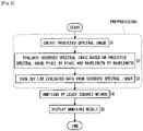
- Fig. 2 is an operational flowchart of the CPU 23. As shown in Fig. 2 , after executing preprocessing constituted by creation processing of a predicted spectral image (step S1), evaluating processing (step S2), and thinning out processing (step S3), the CPU 23 executes unmixing processing (step S4), and displaying processing (step S5). These steps will be described below step by step.
- step S1 Creation Processing of Predicted Spectral Image
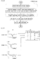
- the CPU 23 refers to spectra of respective pixels of the spectral image F.
- Fig. 3(A) spectral curves of some four pixels (a first pixel, second pixel, third pixel, fourth pixel) are shown.
- the horizontal axis of Fig. 3(A) is a wavelength channel, and the vertical axis thereof is a brightness value.
- the CPU 23 normalizes the spectra of the respective pixels such that their brightness integral values A (the areas of regions each enclosed by the spectral curve and the horizontal axis) become one.
- A the areas of regions each enclosed by the spectral curve and the horizontal axis
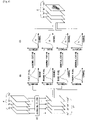
- a spectral image constituted by the spectra after the normalization is represented as F'
- respective wavelength components (channel images) of the spectral image F' are represented as D 1 ', D 2 ', ..., D 32 '.
- the CPU 23 performs averaging filter processing on each of the channel images D 1 ', D 2 ', ..., D 32 '. Consequently, each of the channel images D 1 ', D 2 ', ..., D 32 ' is smoothed in a spatial direction.
- a mask (which is a computational mask), for example, having an opening of three pixels high by three pixels wide is used. This mask is put into the channel image D', and the brightness value of a target pixel located at the center of the opening of the mask is replaced with a brightness mean value of all the pixels in the opening. By repeatedly performing this processing while shifting a mask position on the channel image D', the whole channel image D' is smoothed.
- the CPU 23 denomalizes spectra of the respective pixels constituting the spectral image F" such that their brightness integral values return to the brightness integral values before the normalization (see Fig. 3(A) ).
- an denormalizing coefficient (brightness integral value before normalization/current brightness integral value).
- a spectral image constituted by the spectra after the denormalization is represented as a predicted spectral image E.
- the original spectral image F is called an "observed spectral image F" in order to be distinguished from this predicted spectral image E.
- the CPU 23 refers to a spectrum (predicted spectrum) of some pixel of the predicted spectral image E and a spectrum (observed spectrum) of the same pixel of the observed spectral image F.
- a spectrum predicted spectrum
- a spectrum observed spectrum
- the CPU 23 calculates, as evaluating values of respective wavelength channels of the observed spectrum, distances
- is an absolute value of a brightness difference of an ith wavelength channel.
- has higher reliability, and a wavelength channel with a larger distance
- the CPU 23 performs the above processing on the respective pixels, respectively, to calculate evaluating values
- Fig. 6(A) examples of the evaluating values
- this wavelength channels of some pixel to a threshold value d T predetermined as shown in Fig. 6(A) finds out the one which exceeds the threshold value d T from them, and regards a wavelength channel corresponding thereto as a wavelength channel evaluated particularly low in this pixel.
- this wavelength channel is called a "noise channel”.
- the CPU 23 performs the above processing on all the pixels, respectively, to find noise channels of all the pixels.
- noise channels of the respective pixels are recognized by the CPU 23, for example, as shown in Fig. 6(B) .
- the number of noise channels is sometimes one and sometimes a plural number according to the pixels. Note, however, that if the number of noise channels of some pixel is too large, unmixing of this pixel (described later) becomes difficult, so that it is desirable that the threshold value d T in Fig. 6(A) be preset to such a value that unmixing does not become difficult by experiment or simulation.
- the CPU 23 thins out data on the wavelength channels regarded as the noise channels from the respective pixels of the observed spectral image F. Note, however, that if the data is actually excluded from the observed spectral image F, original data on the observed spectral image F is not saved, so that here, instead of actually excluding the data, the CPU 23 creates a mask matrix M which computationally masks the data and applies it in subsequent steps.
- this mask matrix M an element corresponding to a component to be masked is zero, and an element corresponding to a component other than this is one. The CPU 23 completes this step by the creation of this mask matrix M.
- the CPU 23 reads the emission spectral data of the fluorescent reagents from the hard disk drive 26.
- the emission spectral data represents emission spectra S 1 , S 2 , S 3 of three types of fluorescent reagents (a first reagent, second reagent, third reagent).
- These emission spectra S 1 , S 2 , S 3 are each represented by a one-dimensional matrix such as shown in equation (1).
- S 2 s 12 s 22 s 32 ⁇ s 322
- S 3 s 13 s 23 s 33 ⁇ s 323
- an element S ij in equation (1) is a brightness value of an ith wavelength of a jth reagent.
- the number i of this wavelength corresponds to the number i of the wavelength channel of the observed spectral image F.
- a spectrum f of some pixel of the observed spectral image F is represented by a one-dimensional matrix such as shown in equation (2).
- An element f i is a brightness value of an ith wavelength channel of this pixel.
- Equation (3) holds between the spectrum f of this pixel and the contribution ratios p 1 , p 2 , p 3 .
- this matrix S is called an “emission spectrum S”
- this matrix P is called a “contribution ratio P”.
- S T is a transposed matrix of S.
- the CPU 23 calculates the contribution ratio P by assigning the data on the spectrum f of this pixel contained in the observed spectral image F and the data on the emission spectrum S indicated by the emission spectral data to equation (8). Note, however, that at that time, the CPU 23 applies the mask matrix M (see Fig. 6(B) ) and excludes a term regarding the noise channel of this pixel from equation (8). Consequently, the number of terms of equation (8) (which corresponds to the order of equation (7)) decreases, but the number of terms necessary to calculate the contribution ratio P (order of equation (7)) is secured since the above threshold value d T (see Fig. 6(A) ) is set appropriately. Accordingly, the contribution ratio P to this pixel can be certainly found by the unmixing of this pixel.
- the CPU 23 performs the above unmixing on the respective pixels of the observed spectral image F, respectively, to calculate the contribution ratios P of the respective pixels. Thus, this step is completed.
- the unmixing processing in this step is performed by the well-known least squares method, but by the application of the mask matrix M ( Fig. 6(B) ), components with low reliability of the observed spectral image F are not reflected at all in the computation of the unmixing processing. Accordingly, the accuracy of this unmixing processing becomes higher than that of the conventional one.
- the CPU 23 displays the data on the contribution ratios P (contribution ratios of the respective fluorescent reagents) to the respective pixels found by the unmixing processing on the displaying device 40.
- the data on the contribution ratios P to the respective pixels may be displayed as numeric data, but in order to intuitively inform a user of it, it is desirable that the CPU 23 creates an unmixed image colored according to the contribution ratios P of the respective pixels and displays it.
- the computer 20 of this system evaluates reliability of respective components (here, respective wavelength channel of each pixel) of the observed spectral image F and reflects a result of this evaluation in the unmixing processing, so that robust unmixing processing can be performed on measurement noise Hence, the accuracy of the unmixing processing, that is, the performance of this system is certainly improved.
- a second embodiment of the present invention will be described.
- This embodiment is an embodiment of a spectral imaging fluorescent confocal laser microscope system.
- the point of difference is in the operation of the CPU 23.
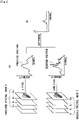
- Fig. 8 is an operational flowchart of the CPU 23 of this embodiment.
- the CPU 23 of this embodiment executes creation processing of a weighting matrix (step S3') instead of the thinning out processing (step S3), and executes unmixing processing by a weighted least squares method (step S4') instead of the unmixing processing by the least squares method (step S4).
- steps S3', S4' will be described below step by step.
- of the respective wavelength channels of each pixel are already calculated (See Fig. 5(A) ).
- the CPU 23 of this step refers to the evaluating values
- the weight values of the respective wavelength channels are reciprocals of the evaluating values
- the CPU 23 creates a weighting matrix W regarding this pixel by the weight values (1/
- the CPU 23 performs the above processing on all the pixels, respectively, to create weighting matrixes W 1 , W 2 , ..., W L (L: number of pixels) of all the pixels as shown in Fig. 9(B) ,, and completes this step.
- W is a weighting matrix of a pixel to be unmixed.
- the CPU 23 calculates the contribution ratio P by assigning data on the spectrum f of this pixel contained in the observed spectral image F, data on the emission spectrum S indicated by the emission spectral data, and the weighting matrix W created regarding this pixel (see equation (9)) to equation (10).
- the error of each wavelength channel (which corresponds to ⁇ in equation (7)) is weighted by the weighting matrix W. Besides, according to this weighting matrix W (see equation (9)), a larger weight is given to the error of each wavelength channel whose reliability is lower.
- the reliability of respective components (here, respective wavelength channels of each pixel) of the observed spectral image F is evaluated and a result of this evaluation is reflected in the unmixing processing, so that the accuracy of the unmixing processing, that is, the performance of this system is certainly improved.
- the standards of the normalization and the denormalization of the spectra are set to the brightness integral value, but may be set to a brightness maximum value or a brightness intermediate value instead of the brightness integral value.
- the averaging filter processing is applied to the smoothing processing, but instead of the averaging filter processing, a different spatial filter processing such as weighted averaging filter processing or median-filter processing may be applied.
- the predicted spectral image E is created by three steps of (1) normalization of the spectra, (2) smoothing in the spatial directions of the spectra, (3) denormalization of the spectra, but the predicted spectral image E may be created by a different step.
- the predicted spectral image E may be the one obtained by simply smoothing the observed spectral image F in the spatial direction.
- the predicted spectral image E is created based on only the observed spectral image F, but may be created based on a different spectral image.
- the predicted spectral image E may be created.
- the operation program of the CPU 23 is previously stored in the hard disk drive 26, but part or all of the program may be installed into the computer 20 from outside via the Internet, a storage medium, or the like.
- each processing is executed by the computer 20, but part or all of the operations of the computer 20 may be executed by a device (control/image processing device) dedicated to the main body of the microscope 10.
- the main body of the microscope 10 of the above respective embodiments uses the multichannel-light detector 19 to detect respective wavelength components of incident light, but instead of the multichannel-light detector 19, a combination of one-channel light detector and a movable mask, a combination of plural one-channel light detectors and plural filters, or the like may be used. Note, however, that the use of the multichannel-light detector 19 enables both simultaneous direction of respective channels and space saving.
- the main body of the microscope 10 of the above respective embodiments is a fluorescent microscope which detects fluorescence generated on the sample 15, but may be a microscope which detects transmitted light or reflected light of light illuminating the sample 15. In this case, instead of the dichroic mirror 12, a beam splitter is used.
- the main body of the microscope 10 of the above respective embodiments is a microscope (confocal microscope) which confocally detects light from the sample 15, but the function of this confocal detection may be omitted. In this case, the pinhole mask 17 becomes unnecessary.
- the main body of the microscope 10 of the above respective embodiments is a scanning microscope which optically scans the sample 15, but may be transformed into a non-scanning microscope. In this case, the optical scanner 13 becomes unnecessary.
- the present invention can be applied to various devices which perform spectral imaging.
Landscapes
- Health & Medical Sciences (AREA)
- Nuclear Medicine, Radiotherapy & Molecular Imaging (AREA)
- Physics & Mathematics (AREA)
- Life Sciences & Earth Sciences (AREA)
- Chemical & Material Sciences (AREA)
- Analytical Chemistry (AREA)
- Biochemistry (AREA)
- General Health & Medical Sciences (AREA)
- General Physics & Mathematics (AREA)
- Immunology (AREA)
- Pathology (AREA)
- Investigating, Analyzing Materials By Fluorescence Or Luminescence (AREA)
- Investigating Or Analysing Materials By The Use Of Chemical Reactions (AREA)
Claims (6)
- Spektralbildverarbeitungsverfahren des Entmischens (S4), auf der Basis eines von einer Probe (15) gewonnenen beobachteten Spektralbildes und von Emissionsspektraldaten von jedem von mehreren in der Probe enthaltenen Materialien, eines Beitrags jedes der genannten mehreren Materialien zu dem genannten beobachteten Spektralbild, gekennzeichnet durch:einen Bewertungsschritt (S2) des Bewertens, auf der Basis eines vorhergesagten Spektralbildes des genannten beobachteten Spektralbildes, wobei das vorhergesagte Spektralbild ein Spektralbild ist, das durch Glätten des genannten beobachteten Spektralbildes in einer räumlichen Richtung erhalten wird, der Zuverlässigkeit jeder Komponente des beobachteten Spektralbildes; undeinen Reflexionsschritt des Reflektierens eines Ergebnisses der genannten Bewertung in einem Inhalt des genannten Entmischens, wobeider Bewertungsschritt (S2) das Berechnen absoluter Abstände zwischen jeweiligen Wellenlängenkanälen des beobachteten Spektrums und entsprechenden Wellenlängenkanälen des vorhergesagten Spektrums beinhaltet, wobei ein Wellenlängenkanal mit einem kleineren absoluten Abstand eine höhere Zuverlässigkeit und ein Wellenlängenkanal mit einem größeren absoluten Abstand eine geringere Zuverlässigkeit hat.
- Spektralbildverarbeitungsverfahren nach Anspruch 1, wobei in dem genannten Bewertungsschritt (S2) die Zuverlässigkeit des genannten beobachteten Spektralbildes in Bezug auf jede Wellenlängenkomponente und jede räumliche Komponente bewertet wird.
- Spektralbildverarbeitungsverfahren nach Anspruch 1 oder 2, wobei in dem genannten Reflexionsschritt eine Komponente des genannten beobachteten Spektralbildes, deren genannte Zuverlässigkeit als niedrig bewertet wird, von einem Berechnungsobjekt der genannten Entmischung ausgeschlossen wird.
- Spektralbildverarbeitungsverfahren nach Anspruch 1 oder 2, wobeidas genannte Entmischen (S4) mit der Gewichtete-Kleinste-Quadrate-Methode des Schätzens des genannten Beitrags nach dem Gewichten des Fehlers jeder Komponente des genannten beobachteten Spektralbildes durchgeführt wird, undin dem genannten Reflexionsschritt ein Inhalt der genannten Gewichtung entsprechend dem Ergebnis der genannten Bewertung festgelegt wird.
- Computerlesbares Speichermedium, auf dem computerausführbare Prozessschritte zum Durchführen des Verfahrens nach einem der Ansprüche 1 bis 4 gespeichert sind.
- Spektralabbildungssystem, das Folgendes umfasst:eine Spektralabbildungseinheit (19), die ein beobachtetes Spektralbild von einer Probe (15) erfasst; undeine Spektralbildverarbeitungseinheit (20), die das erfasste Spektralbild importiert und das Spektralbildverarbeitungsverfahren nach einem der Ansprüche 1 bis 4 ausführt.
Applications Claiming Priority (2)
| Application Number | Priority Date | Filing Date | Title |
|---|---|---|---|
| JP2006046509 | 2006-02-23 | ||
| PCT/JP2007/051699 WO2007097171A1 (ja) | 2006-02-23 | 2007-02-01 | スペクトル画像処理方法、スペクトル画像処理プログラム、及びスペクトルイメージングシステム |
Publications (3)
| Publication Number | Publication Date |
|---|---|
| EP1990630A1 EP1990630A1 (de) | 2008-11-12 |
| EP1990630A4 EP1990630A4 (de) | 2015-09-23 |
| EP1990630B1 true EP1990630B1 (de) | 2022-08-24 |
Family
ID=38437210
Family Applications (1)
| Application Number | Title | Priority Date | Filing Date |
|---|---|---|---|
| EP07707885.5A Not-in-force EP1990630B1 (de) | 2006-02-23 | 2007-02-01 | Spektralbildverarbeitungsverfahren, spektralbildverarbeitungsprogramm und spektralabbildungssystem |
Country Status (4)
| Country | Link |
|---|---|
| US (1) | US8045153B2 (de) |
| EP (1) | EP1990630B1 (de) |
| JP (1) | JP4872914B2 (de) |
| WO (1) | WO2007097171A1 (de) |
Families Citing this family (21)
| Publication number | Priority date | Publication date | Assignee | Title |
|---|---|---|---|---|
| US20090192742A1 (en) * | 2008-01-30 | 2009-07-30 | Mensur Omerbashich | Procedure for increasing spectrum accuracy |
| JP5178226B2 (ja) * | 2008-02-08 | 2013-04-10 | オリンパス株式会社 | 画像処理装置および画像処理プログラム |
| US9581723B2 (en) * | 2008-04-10 | 2017-02-28 | Schlumberger Technology Corporation | Method for characterizing a geological formation traversed by a borehole |
| US8725477B2 (en) | 2008-04-10 | 2014-05-13 | Schlumberger Technology Corporation | Method to generate numerical pseudocores using borehole images, digital rock samples, and multi-point statistics |
| CA3194784A1 (en) | 2008-05-20 | 2009-11-26 | University Health Network | Device and method for fluorescence-based imaging and monitoring |
| JP5228729B2 (ja) * | 2008-09-16 | 2013-07-03 | 株式会社ニコン | スペクトル画像処理方法、スペクトル画像処理プログラム、及びスペクトルイメージングシステム |
| US20110004447A1 (en) * | 2009-07-01 | 2011-01-06 | Schlumberger Technology Corporation | Method to build 3D digital models of porous media using transmitted laser scanning confocal mircoscopy and multi-point statistics |
| US8311788B2 (en) | 2009-07-01 | 2012-11-13 | Schlumberger Technology Corporation | Method to quantify discrete pore shapes, volumes, and surface areas using confocal profilometry |
| JP5721959B2 (ja) * | 2010-03-16 | 2015-05-20 | オリンパス株式会社 | 蛍光内視鏡装置 |
| JP5985140B2 (ja) * | 2010-04-28 | 2016-09-06 | ソニー株式会社 | 蛍光強度補正方法、蛍光強度算出方法及び蛍光強度算出装置 |
| KR101352769B1 (ko) * | 2012-05-09 | 2014-01-22 | 서강대학교산학협력단 | 배경과 관심조직을 구별하는 방법 및 장치 |
| JP5839077B2 (ja) * | 2014-05-02 | 2016-01-06 | 株式会社ニコン | レーザ励起蛍光顕微鏡 |
| DK3171765T3 (da) | 2014-07-24 | 2021-11-01 | Univ Health Network | Indsamling og analyse af data til diagnostiske formål |
| WO2019049442A1 (ja) | 2017-09-08 | 2019-03-14 | ソニー株式会社 | 微小粒子測定装置、情報処理装置および情報処理方法 |
| DE102017221187B4 (de) * | 2017-11-27 | 2020-08-13 | Carl Zeiss Meditec Ag | Verfahren zur Bestimmung der Konzentration von verschiedenen, in einem Objekt enthaltenen Fluoreszenzemittern und Mikroskopiesystem |
| CN118980626A (zh) * | 2018-12-28 | 2024-11-19 | 贝克顿·迪金森公司 | 用于对样本的荧光团进行光谱解析的方法及其系统 |
| WO2021154561A1 (en) * | 2020-01-31 | 2021-08-05 | Becton, Dickinson And Company | Methods and systems for classifying fluorescent flow cytometer data |
| JP2021143988A (ja) * | 2020-03-13 | 2021-09-24 | ソニーグループ株式会社 | 粒子解析システムおよび粒子解析方法 |
| JP7647751B2 (ja) * | 2020-06-30 | 2025-03-18 | ソニーグループ株式会社 | 情報処理装置、情報処理方法、プログラム、顕微鏡システム及び解析システム |
| CN112254814B (zh) * | 2020-10-21 | 2023-04-25 | 辽宁新华印务有限公司 | 多维光谱颜色空间的构建方法、装置和电子设备 |
| DE102022130251A1 (de) * | 2022-11-16 | 2024-05-16 | Carl Zeiss Microscopy Gmbh | Mikroskopanordnung und Verfahren zur Untersuchung einer mit mehreren Farbstoffen gefärbten Probe |
Family Cites Families (31)
| Publication number | Priority date | Publication date | Assignee | Title |
|---|---|---|---|---|
| US5798262A (en) | 1991-02-22 | 1998-08-25 | Applied Spectral Imaging Ltd. | Method for chromosomes classification |
| US5991456A (en) * | 1996-05-29 | 1999-11-23 | Science And Technology Corporation | Method of improving a digital image |
| US6015667A (en) * | 1996-06-03 | 2000-01-18 | The Perkin-Emer Corporation | Multicomponent analysis method including the determination of a statistical confidence interval |
| JP3783815B2 (ja) | 1997-12-18 | 2006-06-07 | 株式会社リコー | 画像処理装置 |
| US6341257B1 (en) * | 1999-03-04 | 2002-01-22 | Sandia Corporation | Hybrid least squares multivariate spectral analysis methods |
| US6415233B1 (en) * | 1999-03-04 | 2002-07-02 | Sandia Corporation | Classical least squares multivariate spectral analysis |
| US6750964B2 (en) * | 1999-08-06 | 2004-06-15 | Cambridge Research And Instrumentation, Inc. | Spectral imaging methods and systems |
| US6888963B2 (en) * | 2000-07-18 | 2005-05-03 | Matsushita Electric Industrial Co., Ltd. | Image processing apparatus and image processing method |
| US6894699B2 (en) * | 2000-07-21 | 2005-05-17 | Mitsubishi Denki Kabushiki Kaisha | Image display device employing selective or asymmetrical smoothing |
| JP3815188B2 (ja) | 2000-07-21 | 2006-08-30 | 三菱電機株式会社 | 画像表示装置および画像表示方法 |
| US20020047907A1 (en) * | 2000-08-30 | 2002-04-25 | Nikon Corporation | Image processing apparatus and storage medium for storing image processing program |
| JP2002152762A (ja) | 2000-08-30 | 2002-05-24 | Nikon Corp | 画像処理装置および画像処理プログラムを記録した記録媒体 |
| JP3690271B2 (ja) * | 2000-11-29 | 2005-08-31 | 株式会社島津製作所 | 核酸の塩基配列決定のためのマトリックス値を得る方法 |
| AU2002331833A1 (en) * | 2001-09-05 | 2003-03-18 | Genicon Sciences Corporation | Method and apparatus for normalization and deconvolution of assay data |
| JP2003083894A (ja) | 2001-09-14 | 2003-03-19 | Sumitomo Electric Ind Ltd | 蛍光値補正方法、蛍光値補正装置、蛍光値補正プログラム及び前記蛍光値補正プログラムを記録した記録媒体 |
| DE10222779A1 (de) * | 2002-05-16 | 2004-03-04 | Carl Zeiss Jena Gmbh | Verfahren und Anordnung zur Untersuchung von Proben |
| US6763308B2 (en) * | 2002-05-28 | 2004-07-13 | Sas Institute Inc. | Statistical outlier detection for gene expression microarray data |
| US6906859B2 (en) * | 2002-06-05 | 2005-06-14 | Nikon Corporation | Epi-illumination apparatus for fluorescent observation and fluorescence microscope having the same |
| US7480083B2 (en) * | 2002-07-30 | 2009-01-20 | Canon Kabushiki Kaisha | Image processing system, apparatus, and method, and color reproduction method |
| JP3903000B2 (ja) * | 2002-11-14 | 2007-04-11 | アークレイ株式会社 | 測定装置、蛍光測定装置及び蛍光測定方法 |
| US7471831B2 (en) * | 2003-01-16 | 2008-12-30 | California Institute Of Technology | High throughput reconfigurable data analysis system |
| US7283684B1 (en) * | 2003-05-20 | 2007-10-16 | Sandia Corporation | Spectral compression algorithms for the analysis of very large multivariate images |
| WO2005013622A1 (ja) | 2003-06-30 | 2005-02-10 | Nikon Corporation | 色成分の混在配列された画像を処理する画像処理装置、画像処理プログラム、電子カメラ、および画像処理方法 |
| US7321791B2 (en) * | 2003-09-23 | 2008-01-22 | Cambridge Research And Instrumentation, Inc. | Spectral imaging of deep tissue |
| WO2005036143A1 (ja) * | 2003-10-10 | 2005-04-21 | Hamamatsu Photonics K.K. | 蛍光色素の濃度を定量する方法およびシステム |
| JP4021414B2 (ja) * | 2003-11-26 | 2007-12-12 | オリンパス株式会社 | スペクトラルデコンボリューション法及びスペクトラルブラインドデコンボリューション法 |
| ATE527619T1 (de) * | 2005-01-27 | 2011-10-15 | Cambridge Res & Instrumentation Inc | Klassifizierung der bildeigenschaften |
| JP4537231B2 (ja) * | 2005-03-07 | 2010-09-01 | 独立行政法人理化学研究所 | 多重蛍光からの蛍光色素濃度の推定方法および多重蛍光からの蛍光強度の推定方法 |
| US20070088535A1 (en) * | 2005-10-17 | 2007-04-19 | Eastman Kodak Company | Generic spectral model for imaging devices |
| US20070099535A1 (en) * | 2005-11-03 | 2007-05-03 | Riebersal Michael A | Water throwing toy |
| WO2007097170A1 (ja) * | 2006-02-23 | 2007-08-30 | Nikon Corporation | スペクトル画像処理方法、コンピュータ実行可能なスペクトル画像処理プログラム、スペクトルイメージングシステム |
-
2007
- 2007-02-01 EP EP07707885.5A patent/EP1990630B1/de not_active Not-in-force
- 2007-02-01 JP JP2007526097A patent/JP4872914B2/ja not_active Expired - Fee Related
- 2007-02-01 WO PCT/JP2007/051699 patent/WO2007097171A1/ja not_active Ceased
- 2007-02-01 US US11/913,294 patent/US8045153B2/en not_active Expired - Fee Related
Also Published As
| Publication number | Publication date |
|---|---|
| JPWO2007097171A1 (ja) | 2009-07-09 |
| US8045153B2 (en) | 2011-10-25 |
| EP1990630A4 (de) | 2015-09-23 |
| EP1990630A1 (de) | 2008-11-12 |
| JP4872914B2 (ja) | 2012-02-08 |
| US20090128806A1 (en) | 2009-05-21 |
| WO2007097171A1 (ja) | 2007-08-30 |
Similar Documents
| Publication | Publication Date | Title |
|---|---|---|
| EP1990630B1 (de) | Spektralbildverarbeitungsverfahren, spektralbildverarbeitungsprogramm und spektralabbildungssystem | |
| US8055035B2 (en) | Spectral image processing method, computer-executable spectral image processing program, and spectral imaging system | |
| US11158049B2 (en) | Methods and systems for assessing histological stains | |
| EP1484595B1 (de) | Farbraum-Transformationen zur Identifikation interessanter Objekte in biologischen Proben | |
| Bolte et al. | A guided tour into subcellular colocalization analysis in light microscopy | |
| US8290236B2 (en) | Quantitative, multispectral image analysis of tissue specimens stained with quantum dots | |
| US8649580B2 (en) | Image processing method, image processing apparatus, and computer-readable recording medium storing image processing program | |
| US20140270474A1 (en) | Detecting Defects on a Wafer | |
| JP2012117813A (ja) | 質量分析データ処理方法及び装置 | |
| US20240393248A1 (en) | Information processing device, biological sample observation system, and image generation method | |
| JP5228729B2 (ja) | スペクトル画像処理方法、スペクトル画像処理プログラム、及びスペクトルイメージングシステム | |
| EP1947441B1 (de) | Vorrichtung zur Bestimmung der Positionen von in einer Probe enthaltenen Objekten | |
| US20120242858A1 (en) | Device and method for compensating for relief in hyperspectral images | |
| US20240329382A1 (en) | Systems and methods for fluorescence microscopy channel crosstalk mitigation | |
| Haaland et al. | Advanced Approaches to Multivariate Curve Resolution Analysis of Hyperspectral Fluorescence Images. |
Legal Events
| Date | Code | Title | Description |
|---|---|---|---|
| PUAI | Public reference made under article 153(3) epc to a published international application that has entered the european phase |
Free format text: ORIGINAL CODE: 0009012 |
|
| 17P | Request for examination filed |
Effective date: 20071030 |
|
| AK | Designated contracting states |
Kind code of ref document: A1 Designated state(s): AT BE BG CH CY CZ DE DK EE ES FI FR GB GR HU IE IS IT LI LT LU LV MC NL PL PT RO SE SI SK TR |
|
| RAP1 | Party data changed (applicant data changed or rights of an application transferred) |
Owner name: NIKON CORPORATION |
|
| DAX | Request for extension of the european patent (deleted) | ||
| RAP1 | Party data changed (applicant data changed or rights of an application transferred) |
Owner name: NIKON CORPORATION |
|
| RA4 | Supplementary search report drawn up and despatched (corrected) |
Effective date: 20150824 |
|
| RIC1 | Information provided on ipc code assigned before grant |
Ipc: G01N 21/64 20060101AFI20150818BHEP |
|
| RIN1 | Information on inventor provided before grant (corrected) |
Inventor name: MIMURA, MASAFUMI Inventor name: OKUGAWA, HISASHI |
|
| STAA | Information on the status of an ep patent application or granted ep patent |
Free format text: STATUS: EXAMINATION IS IN PROGRESS |
|
| 17Q | First examination report despatched |
Effective date: 20191209 |
|
| GRAP | Despatch of communication of intention to grant a patent |
Free format text: ORIGINAL CODE: EPIDOSNIGR1 |
|
| STAA | Information on the status of an ep patent application or granted ep patent |
Free format text: STATUS: GRANT OF PATENT IS INTENDED |
|
| INTG | Intention to grant announced |
Effective date: 20220407 |
|
| GRAS | Grant fee paid |
Free format text: ORIGINAL CODE: EPIDOSNIGR3 |
|
| GRAA | (expected) grant |
Free format text: ORIGINAL CODE: 0009210 |
|
| STAA | Information on the status of an ep patent application or granted ep patent |
Free format text: STATUS: THE PATENT HAS BEEN GRANTED |
|
| AK | Designated contracting states |
Kind code of ref document: B1 Designated state(s): AT BE BG CH CY CZ DE DK EE ES FI FR GB GR HU IE IS IT LI LT LU LV MC NL PL PT RO SE SI SK TR |
|
| REG | Reference to a national code |
Ref country code: GB Ref legal event code: FG4D |
|
| REG | Reference to a national code |
Ref country code: CH Ref legal event code: EP |
|
| REG | Reference to a national code |
Ref country code: IE Ref legal event code: FG4D |
|
| REG | Reference to a national code |
Ref country code: AT Ref legal event code: REF Ref document number: 1513985 Country of ref document: AT Kind code of ref document: T Effective date: 20220915 Ref country code: DE Ref legal event code: R096 Ref document number: 602007061565 Country of ref document: DE |
|
| REG | Reference to a national code |
Ref country code: LT Ref legal event code: MG9D |
|
| REG | Reference to a national code |
Ref country code: NL Ref legal event code: MP Effective date: 20220824 |
|
| PG25 | Lapsed in a contracting state [announced via postgrant information from national office to epo] |
Ref country code: SE Free format text: LAPSE BECAUSE OF FAILURE TO SUBMIT A TRANSLATION OF THE DESCRIPTION OR TO PAY THE FEE WITHIN THE PRESCRIBED TIME-LIMIT Effective date: 20220824 Ref country code: PT Free format text: LAPSE BECAUSE OF FAILURE TO SUBMIT A TRANSLATION OF THE DESCRIPTION OR TO PAY THE FEE WITHIN THE PRESCRIBED TIME-LIMIT Effective date: 20221226 Ref country code: NL Free format text: LAPSE BECAUSE OF FAILURE TO SUBMIT A TRANSLATION OF THE DESCRIPTION OR TO PAY THE FEE WITHIN THE PRESCRIBED TIME-LIMIT Effective date: 20220824 Ref country code: LV Free format text: LAPSE BECAUSE OF FAILURE TO SUBMIT A TRANSLATION OF THE DESCRIPTION OR TO PAY THE FEE WITHIN THE PRESCRIBED TIME-LIMIT Effective date: 20220824 Ref country code: LT Free format text: LAPSE BECAUSE OF FAILURE TO SUBMIT A TRANSLATION OF THE DESCRIPTION OR TO PAY THE FEE WITHIN THE PRESCRIBED TIME-LIMIT Effective date: 20220824 Ref country code: FI Free format text: LAPSE BECAUSE OF FAILURE TO SUBMIT A TRANSLATION OF THE DESCRIPTION OR TO PAY THE FEE WITHIN THE PRESCRIBED TIME-LIMIT Effective date: 20220824 Ref country code: ES Free format text: LAPSE BECAUSE OF FAILURE TO SUBMIT A TRANSLATION OF THE DESCRIPTION OR TO PAY THE FEE WITHIN THE PRESCRIBED TIME-LIMIT Effective date: 20220824 |
|
| REG | Reference to a national code |
Ref country code: AT Ref legal event code: MK05 Ref document number: 1513985 Country of ref document: AT Kind code of ref document: T Effective date: 20220824 |
|
| PG25 | Lapsed in a contracting state [announced via postgrant information from national office to epo] |
Ref country code: PL Free format text: LAPSE BECAUSE OF FAILURE TO SUBMIT A TRANSLATION OF THE DESCRIPTION OR TO PAY THE FEE WITHIN THE PRESCRIBED TIME-LIMIT Effective date: 20220824 Ref country code: IS Free format text: LAPSE BECAUSE OF FAILURE TO SUBMIT A TRANSLATION OF THE DESCRIPTION OR TO PAY THE FEE WITHIN THE PRESCRIBED TIME-LIMIT Effective date: 20221224 Ref country code: GR Free format text: LAPSE BECAUSE OF FAILURE TO SUBMIT A TRANSLATION OF THE DESCRIPTION OR TO PAY THE FEE WITHIN THE PRESCRIBED TIME-LIMIT Effective date: 20221125 |
|
| PG25 | Lapsed in a contracting state [announced via postgrant information from national office to epo] |
Ref country code: RO Free format text: LAPSE BECAUSE OF FAILURE TO SUBMIT A TRANSLATION OF THE DESCRIPTION OR TO PAY THE FEE WITHIN THE PRESCRIBED TIME-LIMIT Effective date: 20220824 Ref country code: DK Free format text: LAPSE BECAUSE OF FAILURE TO SUBMIT A TRANSLATION OF THE DESCRIPTION OR TO PAY THE FEE WITHIN THE PRESCRIBED TIME-LIMIT Effective date: 20220824 Ref country code: CZ Free format text: LAPSE BECAUSE OF FAILURE TO SUBMIT A TRANSLATION OF THE DESCRIPTION OR TO PAY THE FEE WITHIN THE PRESCRIBED TIME-LIMIT Effective date: 20220824 Ref country code: AT Free format text: LAPSE BECAUSE OF FAILURE TO SUBMIT A TRANSLATION OF THE DESCRIPTION OR TO PAY THE FEE WITHIN THE PRESCRIBED TIME-LIMIT Effective date: 20220824 |
|
| REG | Reference to a national code |
Ref country code: DE Ref legal event code: R097 Ref document number: 602007061565 Country of ref document: DE |
|
| PG25 | Lapsed in a contracting state [announced via postgrant information from national office to epo] |
Ref country code: SK Free format text: LAPSE BECAUSE OF FAILURE TO SUBMIT A TRANSLATION OF THE DESCRIPTION OR TO PAY THE FEE WITHIN THE PRESCRIBED TIME-LIMIT Effective date: 20220824 Ref country code: EE Free format text: LAPSE BECAUSE OF FAILURE TO SUBMIT A TRANSLATION OF THE DESCRIPTION OR TO PAY THE FEE WITHIN THE PRESCRIBED TIME-LIMIT Effective date: 20220824 |
|
| PGFP | Annual fee paid to national office [announced via postgrant information from national office to epo] |
Ref country code: DE Payment date: 20221229 Year of fee payment: 17 |
|
| P01 | Opt-out of the competence of the unified patent court (upc) registered |
Effective date: 20230517 |
|
| PLBE | No opposition filed within time limit |
Free format text: ORIGINAL CODE: 0009261 |
|
| STAA | Information on the status of an ep patent application or granted ep patent |
Free format text: STATUS: NO OPPOSITION FILED WITHIN TIME LIMIT |
|
| 26N | No opposition filed |
Effective date: 20230525 |
|
| PG25 | Lapsed in a contracting state [announced via postgrant information from national office to epo] |
Ref country code: SI Free format text: LAPSE BECAUSE OF FAILURE TO SUBMIT A TRANSLATION OF THE DESCRIPTION OR TO PAY THE FEE WITHIN THE PRESCRIBED TIME-LIMIT Effective date: 20220824 |
|
| PG25 | Lapsed in a contracting state [announced via postgrant information from national office to epo] |
Ref country code: MC Free format text: LAPSE BECAUSE OF FAILURE TO SUBMIT A TRANSLATION OF THE DESCRIPTION OR TO PAY THE FEE WITHIN THE PRESCRIBED TIME-LIMIT Effective date: 20220824 |
|
| REG | Reference to a national code |
Ref country code: CH Ref legal event code: PL |
|
| REG | Reference to a national code |
Ref country code: BE Ref legal event code: MM Effective date: 20230228 |
|
| GBPC | Gb: european patent ceased through non-payment of renewal fee |
Effective date: 20230201 |
|
| PG25 | Lapsed in a contracting state [announced via postgrant information from national office to epo] |
Ref country code: LU Free format text: LAPSE BECAUSE OF NON-PAYMENT OF DUE FEES Effective date: 20230201 Ref country code: LI Free format text: LAPSE BECAUSE OF NON-PAYMENT OF DUE FEES Effective date: 20230228 Ref country code: CH Free format text: LAPSE BECAUSE OF NON-PAYMENT OF DUE FEES Effective date: 20230228 |
|
| REG | Reference to a national code |
Ref country code: IE Ref legal event code: MM4A |
|
| PG25 | Lapsed in a contracting state [announced via postgrant information from national office to epo] |
Ref country code: GB Free format text: LAPSE BECAUSE OF NON-PAYMENT OF DUE FEES Effective date: 20230201 |
|
| PG25 | Lapsed in a contracting state [announced via postgrant information from national office to epo] |
Ref country code: IE Free format text: LAPSE BECAUSE OF NON-PAYMENT OF DUE FEES Effective date: 20230201 Ref country code: GB Free format text: LAPSE BECAUSE OF NON-PAYMENT OF DUE FEES Effective date: 20230201 Ref country code: FR Free format text: LAPSE BECAUSE OF NON-PAYMENT OF DUE FEES Effective date: 20230228 |
|
| PG25 | Lapsed in a contracting state [announced via postgrant information from national office to epo] |
Ref country code: BE Free format text: LAPSE BECAUSE OF NON-PAYMENT OF DUE FEES Effective date: 20230228 |
|
| PG25 | Lapsed in a contracting state [announced via postgrant information from national office to epo] |
Ref country code: IT Free format text: LAPSE BECAUSE OF FAILURE TO SUBMIT A TRANSLATION OF THE DESCRIPTION OR TO PAY THE FEE WITHIN THE PRESCRIBED TIME-LIMIT Effective date: 20220824 |
|
| REG | Reference to a national code |
Ref country code: DE Ref legal event code: R119 Ref document number: 602007061565 Country of ref document: DE |
|
| PG25 | Lapsed in a contracting state [announced via postgrant information from national office to epo] |
Ref country code: BG Free format text: LAPSE BECAUSE OF FAILURE TO SUBMIT A TRANSLATION OF THE DESCRIPTION OR TO PAY THE FEE WITHIN THE PRESCRIBED TIME-LIMIT Effective date: 20220824 |
|
| PG25 | Lapsed in a contracting state [announced via postgrant information from national office to epo] |
Ref country code: BG Free format text: LAPSE BECAUSE OF FAILURE TO SUBMIT A TRANSLATION OF THE DESCRIPTION OR TO PAY THE FEE WITHIN THE PRESCRIBED TIME-LIMIT Effective date: 20220824 |
|
| PG25 | Lapsed in a contracting state [announced via postgrant information from national office to epo] |
Ref country code: DE Free format text: LAPSE BECAUSE OF NON-PAYMENT OF DUE FEES Effective date: 20240903 |
|
| PG25 | Lapsed in a contracting state [announced via postgrant information from national office to epo] |
Ref country code: DE Free format text: LAPSE BECAUSE OF NON-PAYMENT OF DUE FEES Effective date: 20240903 |
|
| PG25 | Lapsed in a contracting state [announced via postgrant information from national office to epo] |
Ref country code: CY Free format text: LAPSE BECAUSE OF FAILURE TO SUBMIT A TRANSLATION OF THE DESCRIPTION OR TO PAY THE FEE WITHIN THE PRESCRIBED TIME-LIMIT; INVALID AB INITIO Effective date: 20070201 |
|
| PG25 | Lapsed in a contracting state [announced via postgrant information from national office to epo] |
Ref country code: HU Free format text: LAPSE BECAUSE OF FAILURE TO SUBMIT A TRANSLATION OF THE DESCRIPTION OR TO PAY THE FEE WITHIN THE PRESCRIBED TIME-LIMIT; INVALID AB INITIO Effective date: 20070201 |
|
| PG25 | Lapsed in a contracting state [announced via postgrant information from national office to epo] |
Ref country code: TR Free format text: LAPSE BECAUSE OF FAILURE TO SUBMIT A TRANSLATION OF THE DESCRIPTION OR TO PAY THE FEE WITHIN THE PRESCRIBED TIME-LIMIT Effective date: 20220824 |