EP1990212A1 - Dispositif de sécurité unique pour l'identification et l'authentification de marchandises de valeur, processus de fabrication et processus de sécurisation de marchandises de valeur utilisant une telle sécurité unique - Google Patents
Dispositif de sécurité unique pour l'identification et l'authentification de marchandises de valeur, processus de fabrication et processus de sécurisation de marchandises de valeur utilisant une telle sécurité unique Download PDFInfo
- Publication number
- EP1990212A1 EP1990212A1 EP07107615A EP07107615A EP1990212A1 EP 1990212 A1 EP1990212 A1 EP 1990212A1 EP 07107615 A EP07107615 A EP 07107615A EP 07107615 A EP07107615 A EP 07107615A EP 1990212 A1 EP1990212 A1 EP 1990212A1
- Authority
- EP
- European Patent Office
- Prior art keywords
- security device
- polymers
- blob
- microstructures
- substrate
- Prior art date
- Legal status (The legal status is an assumption and is not a legal conclusion. Google has not performed a legal analysis and makes no representation as to the accuracy of the status listed.)
- Withdrawn
Links
Images


Classifications
-
- G—PHYSICS
- G06—COMPUTING; CALCULATING OR COUNTING
- G06K—GRAPHICAL DATA READING; PRESENTATION OF DATA; RECORD CARRIERS; HANDLING RECORD CARRIERS
- G06K19/00—Record carriers for use with machines and with at least a part designed to carry digital markings
- G06K19/06—Record carriers for use with machines and with at least a part designed to carry digital markings characterised by the kind of the digital marking, e.g. shape, nature, code
- G06K19/08—Record carriers for use with machines and with at least a part designed to carry digital markings characterised by the kind of the digital marking, e.g. shape, nature, code using markings of different kinds or more than one marking of the same kind in the same record carrier, e.g. one marking being sensed by optical and the other by magnetic means
- G06K19/083—Constructional details
- G06K19/086—Constructional details with markings consisting of randomly placed or oriented elements, the randomness of the elements being useable for generating a unique identifying signature of the record carrier, e.g. randomly placed magnetic fibers or magnetic particles in the body of a credit card
-
- B—PERFORMING OPERATIONS; TRANSPORTING
- B42—BOOKBINDING; ALBUMS; FILES; SPECIAL PRINTED MATTER
- B42D—BOOKS; BOOK COVERS; LOOSE LEAVES; PRINTED MATTER CHARACTERISED BY IDENTIFICATION OR SECURITY FEATURES; PRINTED MATTER OF SPECIAL FORMAT OR STYLE NOT OTHERWISE PROVIDED FOR; DEVICES FOR USE THEREWITH AND NOT OTHERWISE PROVIDED FOR; MOVABLE-STRIP WRITING OR READING APPARATUS
- B42D25/00—Information-bearing cards or sheet-like structures characterised by identification or security features; Manufacture thereof
- B42D25/20—Information-bearing cards or sheet-like structures characterised by identification or security features; Manufacture thereof characterised by a particular use or purpose
- B42D25/23—Identity cards
-
- B—PERFORMING OPERATIONS; TRANSPORTING
- B42—BOOKBINDING; ALBUMS; FILES; SPECIAL PRINTED MATTER
- B42D—BOOKS; BOOK COVERS; LOOSE LEAVES; PRINTED MATTER CHARACTERISED BY IDENTIFICATION OR SECURITY FEATURES; PRINTED MATTER OF SPECIAL FORMAT OR STYLE NOT OTHERWISE PROVIDED FOR; DEVICES FOR USE THEREWITH AND NOT OTHERWISE PROVIDED FOR; MOVABLE-STRIP WRITING OR READING APPARATUS
- B42D25/00—Information-bearing cards or sheet-like structures characterised by identification or security features; Manufacture thereof
- B42D25/20—Information-bearing cards or sheet-like structures characterised by identification or security features; Manufacture thereof characterised by a particular use or purpose
- B42D25/29—Securities; Bank notes
-
- B—PERFORMING OPERATIONS; TRANSPORTING
- B42—BOOKBINDING; ALBUMS; FILES; SPECIAL PRINTED MATTER
- B42D—BOOKS; BOOK COVERS; LOOSE LEAVES; PRINTED MATTER CHARACTERISED BY IDENTIFICATION OR SECURITY FEATURES; PRINTED MATTER OF SPECIAL FORMAT OR STYLE NOT OTHERWISE PROVIDED FOR; DEVICES FOR USE THEREWITH AND NOT OTHERWISE PROVIDED FOR; MOVABLE-STRIP WRITING OR READING APPARATUS
- B42D25/00—Information-bearing cards or sheet-like structures characterised by identification or security features; Manufacture thereof
- B42D25/40—Manufacture
- B42D25/405—Marking
- B42D25/43—Marking by removal of material
- B42D25/445—Marking by removal of material using chemical means, e.g. etching
Definitions
- the present invention relates to a unique security device that may be applied on a valuable good to prevent counterfeiting of the latter or to allow its identification or authentication.
- valuable goods on which such a mark may be applied are works of art like paintings, or consumer goods such as watches.
- the invention also concerns a process for the fabrication of such a security device, as well as a method of identification or authentication of a valuable good based on the use of such a security device.
- microstructure(s) will be used not only for designating structures the size of which is of the order of the micron but also for designating more generally structures in the submicron ranges.
- Patent application GB 2 324 065 A discloses a security device comprising, for example, an epoxy resin in which small beads are embedded with a random distribution. Such devices however have become easy to reproduce, given their features and dimensions.
- patent publication WO 2005/104008 discloses a security device comprising a medium in which taggants are embedded according to a random pattern.
- a representation of the random pattern may be obtained by exposing the device to such radiations. The obtained representation may then be compared to a previously recorded reference representation in order to authenticate the object carrying the security device.
- the security device is based mainly on the fact that the taggants are invisible to the human eye, a specific detector being necessary to create the representation to be compared to the reference.
- An object of the present invention is to alleviate the drawbacks of the prior art by proposing a security device which presents structural features making it non-reproducible and, at the same time, readable in efficient and reliable ways.
- blob it is generally meant a geometrical domain having a worm-like shape, regardless its length.
- the lateral size of the considered blobs imaged using optical means should preferably be in the range of 1 ⁇ m to 20 ⁇ m. With current technologies, it is indeed difficult to characterize structures below 1 ⁇ m using a standard optical microscope. Structures larger than 20 ⁇ m are about to be reproduced using state of the art ink-jet printing systems. For fingerprints imaged using Atomic Force Microscope, the considered blob size may further be in the range of 20nm to 1 ⁇ m.
- the material layer may include a film comprising at least a first and a second polymers arranged respectively within a first and a second phases defining the microstructures.
- a third polymer which is a block copolymer based on either the first or the second polymer to which a functional group may further be added in the film, the latter containing optically detectable nanoparticles.
- the functional group is thus advantageously chosen to be able to interact with the nanoparticles so that they are mainly located within the phase corresponding to the polymer on which the block polymer is based.
- the material layer is integral with a part made of PET, quartz, silicon, glass or sapphire, the micro/submicrostructures being defined by etched portions of the material layer having the shape of blob holes.
- the blob holes preferably have a depth substantially between tens of nanometres and a few tens of ⁇ m.
- a security device presenting the required features can be fabricated so that identification or authentication of a valuable good can be implemented in a reliable manner.
- the present invention also relates to a method for securing a valuable good against counterfeiting, comprising the steps consisting in producing a security device according to the present invention, creating a reference image data of the security device to be stored in a security database, applying the security device on a surface of the valuable good, creating a verification image data of at least part of the security device, comparing the verification image data to reference image data stored in the security database, identifying or authenticating the valuable good if the verification image data matches one of the reference image data stored in the security database.
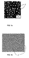
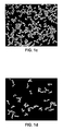
- FIG. 1a, 1b , 1c and 1d show schematic representations, respectively, of an example of a prior art security device image, of an example of a security device image according to the present invention, of the latter after a first filtering operation, and of the same after a second filtering operation;
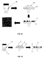
- FIG. 2a shows, schematically, various steps of a process for fabricating a security device corresponding to the representation of FIG. 1b according to a first preferred embodiment
- FIG. 2b shows, schematically, an alternate embodiment of the process illustrated on FIG. 2a ;
- FIG. 2c shows, schematically, further steps of a process for fabricating an alternate security device according to a second preferred embodiment
- FIG. 3 shows a schematic representation of an example of a security device, resulting from the process shown in FIG. 2c ;
- FIG. 4 shows a schematic representation of an optical instrument adapted for the creation of an image of a security device according to the present invention
- FIG. 5a and 5b illustrate, schematically, exemplary operations which may be conducted during analysis of an image of a security device according to the present invention.
- the present invention aims at providing a security device to help preventing counterfeiting of valuable goods, and which can make a corresponding authenticity test of such an item available to a non-expert user.
- stochastic security device or mark
- the stochastic mark has to be made unique and non replicable, even by the process that created it in the first place. In some applications, it is important that the stochastic mark cannot be extracted from an object and placed on another one.
- FIG. 1a illustrates a random pattern that may be fabricated by a demixing process of a two polymer blend, mixed in meta-stable proportions.
- the two polymers are first mixed in an appropriate solvent and, when the latter is removed during a demixing process through which a film is formed, circular spots 1 appears at random locations in the film originating from a phase separation of the polymers. This phenomenon is called “nucleation and growth" and corresponds to the formation of droplets of one of the polymers embedded in a matrix of the second polymer.
- FIG. 1b represents the resulting image taken from a security device comprising a material layer in which, for example, two different phases are randomly distributed on the surface or two different mean height levels are provided, so that the image includes bright and dark zones, here represented in black and white in a non limiting manner.
- FIG. 1b corresponds to a situation where blobs having a Cx value greater than or equal to 2 cover approximately 26% of the security device surface.
- FIG. 1c and FIG. 1d show respective images based on the image of FIG. 1b to which a filtering operation has been applied to let visible only the blobs which present a complexity value Cx larger than, respectively, 2 and 4.
- the use of security devices according to the present invention allows not only to scan the blob positions, as done in the prior art, but also their shapes which leads to an upper degree of reliability in authentication or identification of valuable goods.
- a preferred technique employed to create the random pattern is based on polymer demixing.
- a polymer blend solution 20 consisting of at least two polymers and a solvent is spin coated on a substrate 21 to form a polymer layer having the shape of a thin film 22.
- the starting solution is dilute enough to ensure the coexistence of the two polymers in a single phase.
- solvent evaporates and the concentration increases.
- a threshold concentration reached, the system becomes unstable and phase separates.
- a biphasic polymer film 22 is obtained, each phase corresponding to one of the polymer.
- advantages of this technique are the production of unique stochastic structures, the flexibility of the patterning process, i.e. tunable size and shape of resulting structures, and a potential extension to much smaller features (submicrometer structures).
- phase separation of polymer blends is a well-known effect which occurs both in bulk materials and in thin polymer films. There is a diversity of parameters affecting the final size and morphologies of the structures obtained. Potential parameters to tune the microstructures include:
- spin speed spin speed
- concentration of the solution concentration of the solution
- composition composition, surface energy of the substrate, humidity
- changes in composition will lead in drastic changes in the morphology since the mechanism of phase separation will differ.
- the blend is symmetrical, the system is unstable and the phase separation will follow a spinodal decomposition, the final structure of which is a bi-continuous structure, as apparent from FIG. 1b .
- the range of composition for which a spinodal decomposition is obtained may also differ depending on the respective molecular weight of the two polymers.
- Preferred materials which are suitable for using as a substrate are polymeric (such as PET or polycarbonate), metallic (such as Ti or stainless steel), metal-oxides (such as TiO 2 or sapphire) and silicon-based (such as Silicon, silicon oxides or glass) materials. Other plastics may be used without departing from the scope of the invention.
- polymer pairs suited to create a security device according to the above process are mentioned here, in a non-restricting way: (pairs of polymers which are soluble in organic solvents) PS and PMMA, PS and PVME, PMMA and SAN, PS and PI, PVP and PS, PS and PBrS, PMMA and PVP.
- polymer solutions based on aqueous solvents may also be used to carry out the present invention, such solutions containing pairs of polymers which are soluble in aqueous solvents, such as PVA and PDADMAC.
- PVA and PDADMAC aqueous solvents
- the one skilled in the art will be able to use additional adapted pairs of polymers without going beyond the scope of the present invention.
- the film fabricated through implementation of this process can be used as such, by being applied, eventually glued, on a surface of a valuable good after a reference image data has been created to be stored in a security reference database.
- a verification image data is created by using an appropriate reader, as the one that will be described in connection with FIG. 4 for example, and compared to the reference image data stored in the reference database.
- the valuable good is then identified or authenticated if the verification image data matches one of the reference image data stored in the reference database.
- a first alternate embodiment of the above process of fabrication is provided for improving the legibility of the security device microstructures, by incorporating fluorescent particles, in one of the two phases present in the two polymer device, which will be detected with a fluorescence reader in the verification process. This embodiment is illustrated on FIG. 2b .
- core-shell nanoparticles 25 such as CdSe/ZnS for example, are added to the two polymer blend.
- These fluorescent nanoparticles are first incorporated in the starting polymer blend solution 20 which is then spin coated on the substrate in order to form a thin film 26 as presented on the drawing.
- the two used polymers are polystyrene (PS) and polymethylmethacrylate (PMMA).
- PS polystyrene
- PMMA polymethylmethacrylate
- the polystyrene may be replaced, for example, by a block copolymer containing a block of poly-2-vinyl pyridine which coordinates to the metallic atoms of the nanoparticles.
- PS-b-P2VP block copolymer containing a block of poly-2-vinyl pyridine which coordinates to the metallic atoms of the nanoparticles.
- PS-b-P2VP block copolymer There are two advantages arising from the PS-b-P2VP block copolymer. First, it allows the stabilisation of the nanoparticles and prevents aggregation. Second, it permits the control of the location of the nanoparticles in the phase-separated polymer film. Indeed, in that case the nanoparticle sequester in the PS phase since the block copolymer contains PS and P2VP. The resulting film shows thus structures both in optical and fluorescence microscopy.
- the choice of the block copolymer is however critical since a too long P2VP chain in the block copolymer can lead to the formation of micelles, which modifies strongly the phase separation process.
- the length of the PS block may be of 81 kDa while the length of that of P2VP would be only of 13kDa.
- PS-b-P2VP is more expensive than PS in the given example.
- Such a process may comprise the steps consisting in:
- the polymer thin film containing the nanoparticles can be fabricated on suitable transparent polymer foils which can subsequently be cut in several pieces before being stuck on valuable items and used as a label as previously explained.
- the polymer solution may comprise approximately between 10 and 100g.L -1 of polymer, while the ratio between PS and PS-b-P2VP may preferably be of the order of 50% for the above mentioned reasons. However, this ratio may be different from a technical point of view.
- microstructures having a thickness approximately between 100 and 300nm, while the microstructures had sizes approximately between 5 and 8 ⁇ m, it being possible to get microstructure size approximately between 1 and 10 ⁇ m, by changing the polymer concentration and/or the spin-coating speed.
- the nanoparticles may preferably be CdSe or CdSe/ZnS particles the size of which should be comprised approximately between 1,9 and 5,2nm, so that their corresponding emitting wavelength is included approximately within a 490 to 620 nm range.
- Such nanoparticles are commercially available generally under a ligand stabilized form.
- the ligand should be soluble in the solvent used for the polymer solution.
- the nanoparticle concentration may be adapted as a function of their size.
- the maximal concentrations that have been tested by the Applicant for different nanoparticle sizes are given hereunder in a non-limiting manner:
- alternate functional groups can be used for the block co-polymer.
- phosphines, amines, amides, ammonium, thiols, sulphates, sulphites, disulfide, sulfonic acid, carboxylic, carboxylate groups may also be used for interacting with the nanoparticles.
- the base polymer should preferably be several times heavier than the block co-polymer to avoid formation of micelles in the polymer solution. For example, in the tested case, we can note that PS has a molecular weight six times higher than that of P2VP.
- a second alternate embodiment of the above process of fabrication is provided for improving the legibility of the security device micro/submicrostructures, as illustrated on FIG. 2c .
- this second process allows a better control of both the lateral size and the depth of the microstructures created on the security device.
- a polymer layer or film 22 After a polymer layer or film 22 is created through the process illustrated on FIG. 2a , it may be used to fabricate a metal etch-mask using a lift-off process. This allows implementation of a transfer of the microstructures into the substrate by means of an etching process (wet or dry etching).
- one 27 of the two polymers 27, 28 is dissolved by means of a selective solvent, from step a) to step b) of FIG. 2c .
- a first dry etching is conducted down to the substrate surface in step c), as schematically illustrated by arrows.
- a metal 29 deposition is implemented in step d) before a lift-off operation is conducted in step e) to remove the second polymer 28 down to the substrate 21 surface.
- a second dry etching step is implemented in f) to transfer the microstructures down into the substrate), as schematically illustrated again by arrows.
- the substrate is a PET foil and the dry etching may be done by means of oxygen plasma.
- FIG. 3 shows an AFM image of such a sample.
- This other technology enables to engrave a unique signature directly on the material of a valuable item.
- the glass or the case of a luxury watch may be marked through such a process of engraving.
- the latter offers a broader range of applications and guarantees a better stability over time than the two preceding embodiments.
- the signatures resulting from the transfer of the microstructures may however be replicated using state of the art molding-processes.
- three alternate options are proposed by the applicant.
- the first option consists in filling the micro/submicro-structured surface with a material having a slightly different refractive index than the substrate.
- the second option is to coat the structures with a thin metal layer and fill the micro/submicro-structured surface with a transparent material. For both of these cases, this permits the creation of an optical contrast over the sample and planarizes the surface of the signature.
- the microstructures may be filled with a material containing fluorescent dyes or nanoparticles. The resulting signatures can then be characterized by means of fluorescence microscopy.
- a preferred general method may comprise the steps consisting in producing a security device as previously mentioned, creating a reference image data of the security device to be stored in a security database, applying the security device on a surface of a valuable good, creating a verification image data of at least part of the security device, comparing the verification image data to reference image data stored in the security database, identifying or authenticating the valuable good if the verification image data matches one of the reference image data stored in the security database.
- the above step of creating a verification image data should comprise an operation of reading the security device with a handheld digital microscope including a head intended to be applied against the surface of the valuable good to allow a still positioning of the microscope with respect to the security device during the verification data image creation step.
- FIG. 4 An example of such a microscope 40 is schematically illustrated on FIG. 4 .
- the microscope has an adjustable head 41 screwed on a microscope main tube through a thread 42, and serving two purposes: on the one hand, it allows a setting of the focus distance H between a microscope lens 43 enclosed within the main tube and the examined security device; on the other hand, it ensures that there are no spurious motions between the microscope and the security device thanks to the contact between the head and the substrate. Indeed, it is important to note that if motion occurs, it is impossible to get a sufficiently sharp image for carrying out a later comparison step. This last feature enables a hand-held use of the microscope, even on a vertical surface.
- the distance H can be adjusted by turning the microscope head 41 on its screw thread 42.
- the microscope has a light source 44, which might be a ultra-violet light source (when the polymer film contains fluorescent particles), or a conventional light source, for emitting a light beam which is intended to be reflected by a semi-transparent mirror 45, and focussed on the security device film 22 through the transparent substrate 21.
- the light beam gets absorbed and re-emitted by the film and is projected by the microscope lens 43 on a digital camera 46, while crossing the semi-transparent mirror 45.
- the digital camera is arranged to continuously record and transmit images to a host computer, which then performs a recognition procedure.
- the portable digital microscope may have a 10X magnifying microscope lens, and a digital camera with a pixel pitch which ranges from 2 to 5 ⁇ m (depending on the camera type).
- a digital camera with a pixel pitch which ranges from 2 to 5 ⁇ m (depending on the camera type).
- the security device with a resolution of 0,2 to 0,5 ⁇ m.
- these must ideally have a width of about 2 to 5 ⁇ m (thus a width of 10 pixels).
- the digital microscope may further be provided with an optional optical filter 47.
- the optional filter is advantageously chosen to filter out all the light except a narrow frequency band around the emission frequency of the nanoparticles. This allows enhancing the image contrast, and discards counterfeited fingerprints which have the wrong nanoparticles.
- the above microscope can be put on a standard microscope stand and used without its adjustable head.
- a 20X or a 50X magnifying optics can be used in this case-since everything is static-, which allows for even smaller structures, down to 1 ⁇ m width (below 1 micron the imaging strategy exposed here tends to break down, because it approaches the wavelength of light while having to traverse the substrate).
- Two other devices i.e. a spectrophotometer and a fluorimeter, may be used to verify that the fingerprint has been built with the right process, thus in a complementary way with respect to the use of the digital microscope. These devices may be implemented in their commercially available forms.
- the spectrophotometer aims at delivering a spectrum.
- This spectrum can be correlated to a model spectrum, which corresponds to the one measured with the same spectrophotometer model on a reference security device.
- One spectrum only is needed for all the security devices produced using a given procedure. If a given security device correlation is above a predefined threshold, the device is considered to be build with the right procedure.
- a fluorimeter can be adjusted to the wavelength of the light used to lighten the security device. It measures an emission spectrum for each excitation wavelength. Using correlation on a reference security device recorded with a fluorimeter, it is possible to determine if the device is built with the right process. The use of the fluorimeter is more complex, but will reveal any errors in the materials chosen to build the security device.
- a recognition procedure can be carried out which enables to check the authenticity of a valuable item given the fingerprint data issued from the reading device.
- the image delivered by its video camera is in constant motion and focus changes.
- a selection of the best pictures may consist in writing a real-time routine that measures how sharp the image is, selects the most promising ones and sends an acknowledgement to the system when enough data has been collected. Being able to detect when the image is on focus on the right surface of the fingerprint is not trivial.
- the images are obtained by slightly varying the angle between the microscope and the fingerprint, thus varying the distance between the fingerprint surface and the focal plane.
- 5 sub-images for example may be extracted from the security device image.
- a Fast Fourier Transform may be applied to the sub-images, and the sum of the values may be computed in two circular regions R+ and R-, which are defined according to the stochastic properties of the fingerprint and according to the magnification ratio of the reading device.
- I the fingerprint image
- I* its Fourier transform If ⁇ R + I * 2 > Tp and ⁇ R - I * 2 ⁇ Tm , then the image is assumed to be an image of a fingerprint. Tp and Tm are chosen experimentally.
- the image is accepted if it is an image of a fingerprint and if the 5 sub-images have respective sharpness S 1 to S 5 larger than a threshold Ts, found experimentally.
- the sharpest i.e. the one that has the largest S value is chosen for executing the recognition.
- the signature exhibits sufficient information density.
- the phase blobs exhibit complex shapes.
- a weak identification process may be implemented, for the purpose of aligning a fingerprint image on its reference image (extracted from the security database). It may consist in encoding and extracting only specific parts of the image of the fingerprint. The coordinates of each part is stored with a description of the neighbourhood of that location. When a new image is presented to the system, a similar set of neighbourhoods are extracted and encoded. They are compared to the ones in the security database, and grouped into pairs. Their location in the image is then checked for consistency.
- FIG. 5a illustrates the result of this search on two images of an experimental fingerprint taken under a desktop microscope.
- a neighbourhood of n ⁇ n pixels around location P is stored in a vector B.
- the process can be repeated with blurred and sub-sampled version of I, to form a set of vectors with associated positions and scales V : ⁇ B i , P i ,s i ⁇ .
- the coordinates in P are expressed with respect to the original image size.
- the locations P must be chosen in a systematic way, for example using extrema in a difference of Gaussian pyramid, a Harris-affine detector, a salient region detector or any other known technique that identifies atypical phase blobs using a connected components approach. It is important that once the method is chosen, the system sticks with this method.
- function f () depends of the embodiment of the system. For example, it can be a collection of orientation histograms, a singular value decomposition, a combination of both, or a function that extracts a synthesised description of the phase blobs and their close neighbours.
- T be a fingerprint image to be identified (T stands for "Test image”).
- T stands for "Test image”
- a set of features ⁇ F T ⁇ are extracted from T using the technique just described.
- the next step in the identification process consists in finding corresponding feature pairs F i T ⁇ F j between the reference image I and the test image T.
- the features are paired if they encode the exact same part of the fingerprint in both images.
- two features ⁇ F T i , F j ⁇ are paired if the distance D between them is significantly smaller than the distance between F T i and any other features F k,k ⁇ j in image I, resulting in a feature set pair S, S : ⁇ F T i , P T i , F j , P j ⁇ D ( F T i , F j ) ⁇ d ⁇ D ( F T i , F k ), where d is a parameter tuned on experimental data ( d> 1 ), and D ( ⁇ , ⁇ ) any suitable distance metric, for example the Euclidean distance.
- the last step in the weak identification process verifies that the set of feature pairs ⁇ F T i , F j ⁇ are associated with consistent locations ⁇ P T i P j ⁇ in the image.
- M is a two dimensional transformation
- M ⁇ x ⁇ y ⁇ 1 ⁇ cos ⁇ 2 - sin ⁇ 2 sin ⁇ 2 cos ⁇ 2 ⁇ x y + ⁇ 3 ⁇ 4
- x and y are the horizontal and vertical coordinates in the image, respectively.
- the identification is declared successful if it fulfils the following two conditions:
- a laplacian pyramid is built, a list of local maxima is found, and are located in the corresponding lowpass image of the pyramid as described in A. Oppenheim and R. Schafer, "Discrete-Time Signal Processing", 2nd Ed, Prentice Hall, Engelwood Cliffs, New Jersey 07632, 1989 .
- a local orientation is computed using the local image gradient, and a 17x17 neighbourhood is extracted around the maxima locations.
- the 17 ⁇ 17 neighbourhood can be represented by a vector B of dimension 289.
- the features F are computed by a simple matrix multiplication with matrix R, and have dimension 32.
- a set of vectors F are computed out of the fingerprint image, and are placed in a Kd-Tree structure, using the method described in S. Arya, D. Mount, N. professor, R. Silverman, and A. Wu. "An optimal algorithm for approximate nearest neighbor searching fixed dimensions". Journal of the ACM, 45(6):891-923, 1998 .
- Position, scale and orientation associated with vector F are recorded resulting in a set V : ⁇ F i , P i ,s i ,o i ,ID ⁇ which also contains an ID. There is one single unique ID for each fingerprint.
- the resulting Kd-Tree is stored in the reference image data.
- a list of Vector F (and a list of sets V ) is built using the above described method. For each vector, the closest vector F (contained in set V ) in the Kd-Tree is found using the algorithm described in the last mentioned reference, and the corresponding coordinates P is extracted from set V. This results in a set of coordinate pairs ⁇ P T i , P j ⁇ . The rest of the computation follows exactly the method described in the former section. A coordinate pair is accepted if the matching error is below 5 pixels, and if the subset U of valid pairs is at least as big as 80% of all the feature pairs.
- the fingerprint image is transformed into a binary image. Pixels that have values above a local mean are given value 1, the others are given value 0. To avoid merging two contiguous blobs, a morphological operation of erosion followed by dilation can be performed. Then, a connected component procedure is run. The result is an image whose pixel values are integer indices: the pixels inside a polymer blob have all the same index, and the pixel of two distinct blobs have different values. From this representation, it is trivial to treat each blob separately in a new window.
- the centre of gravity of the blob is used to define the position P of the blob in the image.
- the blob is copied in a n ⁇ n sub-image, where n is large enough to contain the largest blob, and where the centre of gravity of the blob is set in the centre of the image.
- vector F The rest of the computation is exactly the same as in the previous example. More components are just kept in vector F, i.e. the size of vector F should be approximately 30% of the size of vector B.
- I T is called the registered image. Because of imperfections in the reading device, of imperfections in the illumination and of the aging of the fingerprint, the above equation is only approximate.
- the purpose of the strong assessment method is to determine to which extent the registered image I T resembles the image being tested (T).
- the final step consists in synthesising the blob contour comparison D % .
- the number of potentially detected blobs depends on the quality of the test image T.
- the most common distortion of the test image T with respect to the reference image I is blur.
- a measure of blur is performed on image T, by analysing the width of the transition between polymer 1 and polymer 2 on the detected blobs (cf P. Marziliano, F. Dufaux, S. Winkler, and T. Ebrahimi, "A No-Reference Perceptual Blur Metric", IEEE Proc. International Conference on Image Processing, Rochester, NY, Sept. 22-25, 2002 ).
- This width defines the smallest possible blob size S b that can be detected, and also contributes to the measure of confidence of the test.
- the system can ask to take more measurements of the fingerprint. If S b is acceptable, and D % large enough, then the fingerprint passes the strong assessment method.
- the method according to the present invention is unique in the sense that it checks for the shape of blobs. It actually checks first for the shape, then for the position, and finally for the shape and position combination. It does also a check on the statistical properties of the fingerprint, to be able to accept only a family of fingerprint, thus minimising the danger of having fake fingerprints in the system.
- An alternative method of using the features F extracted from a fingerprint image is possible.
- To efficiently retrieve a reference image from the security database that corresponds to a given fingerprint image it is possible to build a huge tree containing all feature sets V of all the existing reference images, using the method described in S. Arya, D. Mount, N. professor, R. Silverman, and A. Wu. "An optimal algorithm for approximate nearest neighbor searching fixed dimensions". Journal of the ACM, 45(6):891-923, 1998 . Then the incoming vectors F are matched to the ones in the tree. For each vector F, n nearest neighbours are found (n ⁇ 10..50 for 1 million images in the database) using approximate nearest neighbor search method.
- the reference image data ID s are collected for each of these n neighbours (of each vector F ), and a weak identification procedure is performed for the reference image data which ID s appear most often. In this way, by performing approximately 10 weak identification procedures a reference image data can be found in a list of 1 million.
- this method requires vector F to be sufficiently discriminative.
- a single vector F must contain a sufficient amount of information to be distinguishable from all the others. This works well when there are enough polymer blobs with a complexity value above 2 in the image. In the contrary, this does not work if the blobs are of circular shape, which have complexity equal to 1, or with blobs whose shape approaches a circle.
- Another advantage of the control over the complexity is that the statistics of the complexity of the polymer blobs can be used to determine if the fingerprint is created by a given process, and provides simple mean to verify for the presence of a fingerprint without having the reference image data.
- the security device image data may be combined to further complementary information in the reference security database, such as a metadata of the secured valuable item which may include a set of data of commercial interest for the application that uses the anti-counterfeiting method (i.e. name of the author for an artwork, name of the owner, ownership history, authenticity check history, name of the expert who created the reference data, date and place of fabrication, etc..), or possibly a visual of the item.
- the recognition method may include additional checking operations related to this complementary information.
Landscapes
- Engineering & Computer Science (AREA)
- Finance (AREA)
- General Physics & Mathematics (AREA)
- Theoretical Computer Science (AREA)
- Business, Economics & Management (AREA)
- Accounting & Taxation (AREA)
- Physics & Mathematics (AREA)
- Chemical & Material Sciences (AREA)
- Chemical Kinetics & Catalysis (AREA)
- General Chemical & Material Sciences (AREA)
- Manufacturing & Machinery (AREA)
- Credit Cards Or The Like (AREA)
- Investigating, Analyzing Materials By Fluorescence Or Luminescence (AREA)
- Inspection Of Paper Currency And Valuable Securities (AREA)
Priority Applications (6)
| Application Number | Priority Date | Filing Date | Title |
|---|---|---|---|
| EP07107615A EP1990212A1 (fr) | 2007-05-07 | 2007-05-07 | Dispositif de sécurité unique pour l'identification et l'authentification de marchandises de valeur, processus de fabrication et processus de sécurisation de marchandises de valeur utilisant une telle sécurité unique |
| PCT/EP2008/055606 WO2008135586A2 (fr) | 2007-05-07 | 2008-05-07 | Dispositif de sécurité unique pour identification ou authentification de biens de valeur, processus de fabrication et procédé pour sécuriser des biens de valeur au moyen dudit dispositif de sécurité |
| DE602008004832T DE602008004832D1 (de) | 2007-05-07 | 2008-05-07 | Einmalige sicherheitsvorrichtung zur identifizierung oder authentifizierung hochwertiger güter, hersrtiger güter mit einer solchen einmaligen sicherheitsvorrichtung |
| US12/599,412 US9430733B2 (en) | 2007-05-07 | 2008-05-07 | Unique security device for the identification or authentication of valuable goods, fabrication process and method for securing valuable goods using such a unique security device |
| AT08750128T ATE497446T1 (de) | 2007-05-07 | 2008-05-07 | Einmalige sicherheitsvorrichtung zur identifizierung oder authentifizierung hochwertiger güter, herstellungsverfahren und verfahren zum sichern hochwertiger güter mit einer solchen einmaligen sicherheitsvorrichtung |
| EP08750128A EP2142380B1 (fr) | 2007-05-07 | 2008-05-07 | Dispositif de sécurité unique pour l'identification et l'authentification de marchandises de valeur, processus de fabrication et processus de sécurisation de marchandises de valeur utilisant une telle sécurité unique |
Applications Claiming Priority (1)
| Application Number | Priority Date | Filing Date | Title |
|---|---|---|---|
| EP07107615A EP1990212A1 (fr) | 2007-05-07 | 2007-05-07 | Dispositif de sécurité unique pour l'identification et l'authentification de marchandises de valeur, processus de fabrication et processus de sécurisation de marchandises de valeur utilisant une telle sécurité unique |
Publications (1)
| Publication Number | Publication Date |
|---|---|
| EP1990212A1 true EP1990212A1 (fr) | 2008-11-12 |
Family
ID=38662698
Family Applications (2)
| Application Number | Title | Priority Date | Filing Date |
|---|---|---|---|
| EP07107615A Withdrawn EP1990212A1 (fr) | 2007-05-07 | 2007-05-07 | Dispositif de sécurité unique pour l'identification et l'authentification de marchandises de valeur, processus de fabrication et processus de sécurisation de marchandises de valeur utilisant une telle sécurité unique |
| EP08750128A Active EP2142380B1 (fr) | 2007-05-07 | 2008-05-07 | Dispositif de sécurité unique pour l'identification et l'authentification de marchandises de valeur, processus de fabrication et processus de sécurisation de marchandises de valeur utilisant une telle sécurité unique |
Family Applications After (1)
| Application Number | Title | Priority Date | Filing Date |
|---|---|---|---|
| EP08750128A Active EP2142380B1 (fr) | 2007-05-07 | 2008-05-07 | Dispositif de sécurité unique pour l'identification et l'authentification de marchandises de valeur, processus de fabrication et processus de sécurisation de marchandises de valeur utilisant une telle sécurité unique |
Country Status (5)
| Country | Link |
|---|---|
| US (1) | US9430733B2 (fr) |
| EP (2) | EP1990212A1 (fr) |
| AT (1) | ATE497446T1 (fr) |
| DE (1) | DE602008004832D1 (fr) |
| WO (1) | WO2008135586A2 (fr) |
Cited By (6)
| Publication number | Priority date | Publication date | Assignee | Title |
|---|---|---|---|---|
| US20100108874A1 (en) * | 2007-05-23 | 2010-05-06 | Loessil Fariborz Martin Zahedi | Film element for detecting authenticity |
| ITMI20091635A1 (it) * | 2009-09-25 | 2011-03-26 | Augusto Capello | Procedura di autenticazione mediante codici univoci |
| EP2333749A1 (fr) * | 2009-12-10 | 2011-06-15 | Universität Bayreuth | Empreinte artificielle |
| WO2015128350A1 (fr) * | 2014-02-26 | 2015-09-03 | Georg-August-Universität Göttingen Stiftung Öffentlichen Rechts | Identification d'un objet original de manière infalsifiable |
| EP3407559A1 (fr) * | 2017-05-26 | 2018-11-28 | Authentic Vision GmbH | Système et procédé de gestion de privilèges basé sur l'authentification d'un dispositif de sécurité non clonable |
| WO2020162177A1 (fr) * | 2019-02-05 | 2020-08-13 | 東京応化工業株式会社 | Objet d'authentification, système d'authentification et procédé de production de support d'utilisation d'authentification |
Families Citing this family (23)
| Publication number | Priority date | Publication date | Assignee | Title |
|---|---|---|---|---|
| GB0702092D0 (en) * | 2007-02-02 | 2007-03-14 | Fracture Code Corp Aps | Graphic Code Application Apparatus and Method |
| EP2073175A1 (fr) * | 2007-12-17 | 2009-06-24 | Gemalto SA | Support d'identification sécurisé et procédé de sécurisation d'un tel support |
| FR2934709B1 (fr) * | 2008-08-01 | 2010-09-10 | Commissariat Energie Atomique | Structure d'echange thermique et dispositif de refroidissement comportant une telle structure. |
| US8253536B2 (en) * | 2009-04-22 | 2012-08-28 | Simon Fraser University | Security document with electroactive polymer power source and nano-optical display |
| US8659391B2 (en) * | 2009-08-18 | 2014-02-25 | Indian Institute Of Technology Madras | Multielement and multiproperty tagging |
| US9176105B2 (en) | 2010-08-20 | 2015-11-03 | President And Fellows Of Harvard College | Density-based separation of biological analytes using multiphase systems |
| EP4152278A1 (fr) * | 2011-03-17 | 2023-03-22 | New York University | Systèmes, procédés et supports accessibles par ordinateur pour authentification et vérification d'objets physiques |
| US9461193B2 (en) * | 2011-05-13 | 2016-10-04 | The Regents Of The University Of Michigan | Focusing luminescent and thermal radiation concentrators |
| US8657114B2 (en) * | 2011-06-03 | 2014-02-25 | Kimberly-Clark Worldwide, Inc. | Package with contrasting graphics |
| US8939955B2 (en) | 2011-06-03 | 2015-01-27 | Kimberly-Clark Worldwide, Inc. | Absorbent article with contrasting wrapper graphics |
| WO2013143829A2 (fr) * | 2012-03-27 | 2013-10-03 | Sicpa Holding Sa | Flocon multicouches comportant un haut niveau de codage |
| US9589343B2 (en) * | 2012-09-27 | 2017-03-07 | Hitachi High-Technologies Corporation | Pattern measurement device, evaluation method of polymer compounds used in self-assembly lithography, and computer program |
| US9903821B2 (en) | 2013-05-01 | 2018-02-27 | Indian Institute Of Technology Madras | Coated mesoflowers for molecular detection and smart barcode materials |
| EP3066612B1 (fr) | 2013-11-07 | 2019-01-02 | Scantrust SA | Code à barres bidimensionnel et son procédé d'authentification |
| US9424653B2 (en) * | 2014-04-29 | 2016-08-23 | Adobe Systems Incorporated | Method and apparatus for identifying a representative area of an image |
| US9694518B2 (en) * | 2014-06-20 | 2017-07-04 | The Regents Of The University Of Michigan | Breath-activated images and anti-counterfeit authentication features formed of nanopillar arrays |
| MA40917A (fr) * | 2014-11-03 | 2017-09-12 | Micali Silvio | Prévention de la contrefaçon |
| US9418327B1 (en) * | 2016-01-29 | 2016-08-16 | International Business Machines Corporation | Security key system |
| KR101953123B1 (ko) * | 2016-09-23 | 2019-02-28 | 현대자동차주식회사 | 패턴이 형성되는 잠금 키와, 이에 결합하는 키 박스와, 이들을 포함하는 잠금 유닛과, 이를 제조하는 방법 |
| JP7048064B2 (ja) * | 2016-09-30 | 2022-04-05 | 株式会社環境レジリエンス | 個別認証媒体を用いた個別認証システム |
| US10312200B2 (en) | 2017-07-27 | 2019-06-04 | International Business Machines Corporation | Integrated circuit security |
| WO2022032199A1 (fr) * | 2020-08-06 | 2022-02-10 | Arizona Board Of Regents On Behalf Of Arizona State University | Formation de dendrites pour marquage sécurisé au moyen de systèmes multi-fluides |
| DE102021110607A1 (de) * | 2021-04-26 | 2022-10-27 | Semikron Elektronik Gmbh & Co. Kg | Gerät mit Funktionskomponente und Kunststoffgehäuseelement und Verfahren zur Überprüfung der Echtheit eines solches Geräts |
Citations (10)
| Publication number | Priority date | Publication date | Assignee | Title |
|---|---|---|---|---|
| GB2221870A (en) * | 1988-05-31 | 1990-02-21 | De La Rue Co Plc | Security device |
| US5719939A (en) * | 1990-06-15 | 1998-02-17 | Unicate B.V. | System and method of verifying the legitimacy of a product against forgery |
| GB2324065A (en) * | 1997-04-09 | 1998-10-14 | James Howard Slater | An identification code for banknotes or credit cards comprising a pattern of random beads |
| US6309690B1 (en) * | 1999-04-01 | 2001-10-30 | Microtrace, Inc. | System for retrospective identification and method of marking articles for retrospective identification |
| DE10155780A1 (de) * | 2001-11-14 | 2003-05-22 | Vision Tools Hard Und Software | Verfahren und Anordnung zur Sicherung von Gegenständen gegen Fälschung und/oder Nachahmung, optional in Verbindung mit der Identifikation der ungefälschten Gegenstände |
| DE10204870A1 (de) * | 2002-02-06 | 2003-08-14 | Infineon Technologies Ag | Verfahren zur Fälschungssicherung eines Wertträgers, Wertträger und Verfahren zur Überprüfung seiner Echtheit |
| WO2004070667A2 (fr) * | 2003-02-05 | 2004-08-19 | Informium Ag | Procede de production de marques de securite |
| WO2005080088A1 (fr) * | 2004-02-18 | 2005-09-01 | Tullis Russel Papermakers Limited | Appareil et procede d'identification d'un objet presentant des elements d'identification repartis de maniere aleatoire |
| US20050239207A1 (en) * | 2004-04-22 | 2005-10-27 | Daniel Gelbart | Covert authentication method and apparatus |
| WO2006022808A2 (fr) * | 2004-08-11 | 2006-03-02 | Victor Zazzu | Carte comportant des caracteristiques de securite ameliorees |
Family Cites Families (3)
| Publication number | Priority date | Publication date | Assignee | Title |
|---|---|---|---|---|
| ATE410315T1 (de) * | 2003-04-30 | 2008-10-15 | Hewlett Packard Development Co | Authentifizierungsverfahren und -system |
| ATE504909T1 (de) | 2005-06-29 | 2011-04-15 | Eidgenoess Tech Hochschule | Eindeutige label für ein identifikations- oder sicherheitssystem |
| US7549592B2 (en) * | 2006-10-31 | 2009-06-23 | Xerox Corporation | Method for embedding machine-readable information with fluorescent materials |
-
2007
- 2007-05-07 EP EP07107615A patent/EP1990212A1/fr not_active Withdrawn
-
2008
- 2008-05-07 DE DE602008004832T patent/DE602008004832D1/de active Active
- 2008-05-07 US US12/599,412 patent/US9430733B2/en active Active
- 2008-05-07 AT AT08750128T patent/ATE497446T1/de not_active IP Right Cessation
- 2008-05-07 EP EP08750128A patent/EP2142380B1/fr active Active
- 2008-05-07 WO PCT/EP2008/055606 patent/WO2008135586A2/fr active Application Filing
Patent Citations (10)
| Publication number | Priority date | Publication date | Assignee | Title |
|---|---|---|---|---|
| GB2221870A (en) * | 1988-05-31 | 1990-02-21 | De La Rue Co Plc | Security device |
| US5719939A (en) * | 1990-06-15 | 1998-02-17 | Unicate B.V. | System and method of verifying the legitimacy of a product against forgery |
| GB2324065A (en) * | 1997-04-09 | 1998-10-14 | James Howard Slater | An identification code for banknotes or credit cards comprising a pattern of random beads |
| US6309690B1 (en) * | 1999-04-01 | 2001-10-30 | Microtrace, Inc. | System for retrospective identification and method of marking articles for retrospective identification |
| DE10155780A1 (de) * | 2001-11-14 | 2003-05-22 | Vision Tools Hard Und Software | Verfahren und Anordnung zur Sicherung von Gegenständen gegen Fälschung und/oder Nachahmung, optional in Verbindung mit der Identifikation der ungefälschten Gegenstände |
| DE10204870A1 (de) * | 2002-02-06 | 2003-08-14 | Infineon Technologies Ag | Verfahren zur Fälschungssicherung eines Wertträgers, Wertträger und Verfahren zur Überprüfung seiner Echtheit |
| WO2004070667A2 (fr) * | 2003-02-05 | 2004-08-19 | Informium Ag | Procede de production de marques de securite |
| WO2005080088A1 (fr) * | 2004-02-18 | 2005-09-01 | Tullis Russel Papermakers Limited | Appareil et procede d'identification d'un objet presentant des elements d'identification repartis de maniere aleatoire |
| US20050239207A1 (en) * | 2004-04-22 | 2005-10-27 | Daniel Gelbart | Covert authentication method and apparatus |
| WO2006022808A2 (fr) * | 2004-08-11 | 2006-03-02 | Victor Zazzu | Carte comportant des caracteristiques de securite ameliorees |
Cited By (12)
| Publication number | Priority date | Publication date | Assignee | Title |
|---|---|---|---|---|
| US20100108874A1 (en) * | 2007-05-23 | 2010-05-06 | Loessil Fariborz Martin Zahedi | Film element for detecting authenticity |
| ITMI20091635A1 (it) * | 2009-09-25 | 2011-03-26 | Augusto Capello | Procedura di autenticazione mediante codici univoci |
| EP2333749A1 (fr) * | 2009-12-10 | 2011-06-15 | Universität Bayreuth | Empreinte artificielle |
| WO2011069630A1 (fr) | 2009-12-10 | 2011-06-16 | Universität Bayreuth | Empreinte digitale artificielle |
| WO2015128350A1 (fr) * | 2014-02-26 | 2015-09-03 | Georg-August-Universität Göttingen Stiftung Öffentlichen Rechts | Identification d'un objet original de manière infalsifiable |
| US9659360B2 (en) | 2014-02-26 | 2017-05-23 | Georg-August-Universitaet Goettingen Stiftung Oeffentlichen Rechts | Identifying an original object in a forgery-proof way |
| EP3407559A1 (fr) * | 2017-05-26 | 2018-11-28 | Authentic Vision GmbH | Système et procédé de gestion de privilèges basé sur l'authentification d'un dispositif de sécurité non clonable |
| WO2018215637A1 (fr) * | 2017-05-26 | 2018-11-29 | Authentic Vision Gmbh | Système et procédé de gestion de privilèges |
| US12052262B2 (en) | 2017-05-26 | 2024-07-30 | Authentic Vision Gmbh | System and method to manage privileges |
| WO2020162177A1 (fr) * | 2019-02-05 | 2020-08-13 | 東京応化工業株式会社 | Objet d'authentification, système d'authentification et procédé de production de support d'utilisation d'authentification |
| CN113396412A (zh) * | 2019-02-05 | 2021-09-14 | 东京应化工业株式会社 | 被认证物、认证系统以及认证用介质的生成方法 |
| JPWO2020162177A1 (ja) * | 2019-02-05 | 2021-12-02 | 東京応化工業株式会社 | 被認証物、認証システム、及び認証用媒体の生成方法 |
Also Published As
| Publication number | Publication date |
|---|---|
| WO2008135586A2 (fr) | 2008-11-13 |
| US9430733B2 (en) | 2016-08-30 |
| EP2142380A2 (fr) | 2010-01-13 |
| WO2008135586A3 (fr) | 2009-01-08 |
| ATE497446T1 (de) | 2011-02-15 |
| US20100195916A1 (en) | 2010-08-05 |
| DE602008004832D1 (de) | 2011-03-17 |
| EP2142380B1 (fr) | 2011-02-02 |
Similar Documents
| Publication | Publication Date | Title |
|---|---|---|
| EP1990212A1 (fr) | Dispositif de sécurité unique pour l'identification et l'authentification de marchandises de valeur, processus de fabrication et processus de sécurisation de marchandises de valeur utilisant une telle sécurité unique | |
| EP1747540B1 (fr) | Procede de reconnaissance et de suivi de supports fibreux, ainsi que les applications d'un tel procede dans le domaine informatique notamment | |
| KR101355389B1 (ko) | 편광입자를 사용하여 문서나 아이템에 마킹하는 방법, 마킹된 문서 또는 아이템을 식별하는 방법 및 장치 | |
| EA023501B1 (ru) | Аутентификационная метка, способ ее изготовления и способ проверки подлинности продукта, содержащего ее | |
| CN102955930B (zh) | 一种利用物质自身物理特征识别的防伪方法和系统 | |
| US20100008590A1 (en) | Signature of Moulded Article | |
| JP5763071B2 (ja) | セキュリティ文書、特に紙幣の認証 | |
| DE102018108741A1 (de) | Verfahren für optische Produktauthentifizierung | |
| EP3380987B1 (fr) | Procede d'authentification et/ou de controle d'integrite d'un sujet | |
| CN111695658A (zh) | 一种基于puf的防伪方法、puf防伪标签及其制备方法 | |
| CA3000153A1 (fr) | Procede d'analyse d'un document structure susceptible d'etre deforme | |
| US20210157888A1 (en) | Secure access with dendritic identifiers | |
| US11823003B2 (en) | Method for authenticating a magnetically induced mark with a portable device | |
| Centeno et al. | Identity Document and banknote security forensics: a survey | |
| WO2023069471A9 (fr) | Authentification d'identifiants par diffusion de lumière | |
| US20230377115A1 (en) | Anti-tamper protection using dendrites | |
| Nieto‐Villena et al. | Atomic force microscopy as a tool for binder identification in ancient photographic processes | |
| FR3011768A1 (fr) | Procede de marquage de produits manufactures | |
| DE102008016803A1 (de) | Authentifizierung von Objekten mittels Bilderkennung | |
| WO2020025790A1 (fr) | Procede de securisation d'une bouteille et verification de la bouteille. | |
| EP3810432A1 (fr) | Procédé pour délivrer à un objet une marque unique | |
| Patel et al. | Versatile authentication using an identifier based on optical variable nanostructures | |
| Penn et al. | Nanobarcodes particles as covert security tags for documents and product security | |
| Berenguel Centeno | Analysis of background textures in banknotes and identity documents for counterfeit detection | |
| 배형종 | PROGRAMMABLE WRINKLE PATTERNING ON MICROPARTICLES |
Legal Events
| Date | Code | Title | Description |
|---|---|---|---|
| PUAI | Public reference made under article 153(3) epc to a published international application that has entered the european phase |
Free format text: ORIGINAL CODE: 0009012 |
|
| AK | Designated contracting states |
Kind code of ref document: A1 Designated state(s): AT BE BG CH CY CZ DE DK EE ES FI FR GB GR HU IE IS IT LI LT LU LV MC MT NL PL PT RO SE SI SK TR |
|
| AX | Request for extension of the european patent |
Extension state: AL BA HR MK RS |
|
| AKX | Designation fees paid | ||
| REG | Reference to a national code |
Ref country code: DE Ref legal event code: 8566 |
|
| STAA | Information on the status of an ep patent application or granted ep patent |
Free format text: STATUS: THE APPLICATION IS DEEMED TO BE WITHDRAWN |
|
| 18D | Application deemed to be withdrawn |
Effective date: 20090513 |