EP1989758B1 - Antenna system configuration for mobile phones - Google Patents
Antenna system configuration for mobile phones Download PDFInfo
- Publication number
- EP1989758B1 EP1989758B1 EP06839451A EP06839451A EP1989758B1 EP 1989758 B1 EP1989758 B1 EP 1989758B1 EP 06839451 A EP06839451 A EP 06839451A EP 06839451 A EP06839451 A EP 06839451A EP 1989758 B1 EP1989758 B1 EP 1989758B1
- Authority
- EP
- European Patent Office
- Prior art keywords
- antenna
- mobile phone
- mhz
- flip
- hearing aid
- Prior art date
- Legal status (The legal status is an assumption and is not a legal conclusion. Google has not performed a legal analysis and makes no representation as to the accuracy of the status listed.)
- Ceased
Links
- 230000005669 field effect Effects 0.000 claims abstract description 4
- 230000001808 coupling effect Effects 0.000 claims description 3
- 238000000926 separation method Methods 0.000 abstract description 4
- 230000005404 monopole Effects 0.000 description 7
- 238000004891 communication Methods 0.000 description 4
- 230000008878 coupling Effects 0.000 description 3
- 238000010168 coupling process Methods 0.000 description 3
- 238000005859 coupling reaction Methods 0.000 description 3
- 230000005672 electromagnetic field Effects 0.000 description 3
- 239000003990 capacitor Substances 0.000 description 2
- 230000000694 effects Effects 0.000 description 2
- 238000011156 evaluation Methods 0.000 description 2
- 238000005259 measurement Methods 0.000 description 2
- 230000006978 adaptation Effects 0.000 description 1
- 239000000969 carrier Substances 0.000 description 1
- 238000000034 method Methods 0.000 description 1
- 230000001902 propagating effect Effects 0.000 description 1
Images


Classifications
-
- H—ELECTRICITY
- H01—ELECTRIC ELEMENTS
- H01Q—ANTENNAS, i.e. RADIO AERIALS
- H01Q1/00—Details of, or arrangements associated with, antennas
- H01Q1/12—Supports; Mounting means
- H01Q1/22—Supports; Mounting means by structural association with other equipment or articles
- H01Q1/24—Supports; Mounting means by structural association with other equipment or articles with receiving set
- H01Q1/241—Supports; Mounting means by structural association with other equipment or articles with receiving set used in mobile communications, e.g. GSM
- H01Q1/242—Supports; Mounting means by structural association with other equipment or articles with receiving set used in mobile communications, e.g. GSM specially adapted for hand-held use
- H01Q1/245—Supports; Mounting means by structural association with other equipment or articles with receiving set used in mobile communications, e.g. GSM specially adapted for hand-held use with means for shaping the antenna pattern, e.g. in order to protect user against rf exposure
-
- H—ELECTRICITY
- H01—ELECTRIC ELEMENTS
- H01Q—ANTENNAS, i.e. RADIO AERIALS
- H01Q1/00—Details of, or arrangements associated with, antennas
- H01Q1/12—Supports; Mounting means
- H01Q1/22—Supports; Mounting means by structural association with other equipment or articles
- H01Q1/24—Supports; Mounting means by structural association with other equipment or articles with receiving set
- H01Q1/241—Supports; Mounting means by structural association with other equipment or articles with receiving set used in mobile communications, e.g. GSM
- H01Q1/242—Supports; Mounting means by structural association with other equipment or articles with receiving set used in mobile communications, e.g. GSM specially adapted for hand-held use
- H01Q1/243—Supports; Mounting means by structural association with other equipment or articles with receiving set used in mobile communications, e.g. GSM specially adapted for hand-held use with built-in antennas
- H01Q1/244—Supports; Mounting means by structural association with other equipment or articles with receiving set used in mobile communications, e.g. GSM specially adapted for hand-held use with built-in antennas extendable from a housing along a given path
-
- H—ELECTRICITY
- H04—ELECTRIC COMMUNICATION TECHNIQUE
- H04B—TRANSMISSION
- H04B1/00—Details of transmission systems, not covered by a single one of groups H04B3/00 - H04B13/00; Details of transmission systems not characterised by the medium used for transmission
- H04B1/38—Transceivers, i.e. devices in which transmitter and receiver form a structural unit and in which at least one part is used for functions of transmitting and receiving
- H04B1/3827—Portable transceivers
- H04B1/3833—Hand-held transceivers
- H04B1/3838—Arrangements for reducing RF exposure to the user, e.g. by changing the shape of the transceiver while in use
Definitions
- a hearing aid operates by using a microphone to pick up sound waves in the air and convert the sound waves to electrical signals. The signals are then amplified as needed and converted back to audible sounds for the user to hear.
- the hearing aid microphone does not always work well in conjunction with audio devices like mobile phone handsets.
- the acoustic connection made between the audio device and the hearing aid can be poor and can create distortions in the sound.
- the surrounding noise in the area of the user is often picked up by the hearing aid and interferes with the desired audio.
- RF radio frequency
- US 2006/0009156 A1 discloses a mobile phone with improved hearing aid compatibility.
- US 6147651 , EP 10 69 641 and DE 19639642 relate to extendable mobile phone antennas of the prior art.
- HAC hearing aid compatibility
- the FCC defines HAC for mobile phones in terms of two parameters; radio-frequency (RF) emissions (M-scale) and telecoil coupling (T-scale).
- RF radio-frequency
- T-scale telecoil coupling
- Mobile phones that comply with the FCC's hearing aid compatibility rule must receive a minimum rating of M3 for RF emissions and T3 for telecoil coupling.
- the FCC requires that nationwide carriers offer a range of phones that comply with HAC regulations beginning in September 2005 for microphone (M) mode and in September 2006 for (T) telecoil mode.
- HAC hearing aid compatibility
- Handsets that receive a hearing aid compatibility rating of M3 or M4 have met or surpassed the ANSI hearing aid compatibility standard as adopted by the Federal Communications Commission.
- An M3-rating indicates the mobile phone has satisfied the ANSI standard.
- An M4-rating indicates the mobile phone has exceeded the ANSI standard. The higher the M-rating the mobile phone has the lower the radio frequency (RF) emissions level and higher signal quality the mobile phone will have to the hearing aid device, assuming that the phone is still performing efficiently.
- RF radio frequency
- T rating refers to a mobile phone's coupling ability and is intended for use with hearing aids in the telecoil mode. The higher the "T” number the more likely you will be able to use your phone with your hearing aid in telecoil mode.
- the FCC regulations require that cell phones be manufactured for use with hearing aids on telecoil setting by September 2006. For purposes of the present invention, however, only the M rating aspect of HAC is addressed.
- a phone For a phone to be HAC compliant, it must be compliant in all US frequency bands of operation for mobile phones. These include the 850-MHz and 1900-MHz bands. Moreover, the mobile phones must, in these operating bands, exhibit, at a minimum, an M3 rating meaning RF emissions from a digital wireless mobile phone are not to exceed -11.9 dB A/m for H-field and 38.6 dB V/m for E-field. To the inventor's best knowledge, there has not been any mobile phone that meets the M3 rating concurrently in the 850-MHz and 1900-MHz frequency bands of operation.
- a flip type mobile phone that includes a speaker component near the top end of the upper flip portion of the mobile phone and an extendable antenna configuration in a retracted position.
- the antenna configuration is designed to reduce, to a hearing aid compatibility (HAC) M3 rating or better, any scattered EM field effects that can cause interference to an active hearing aid when the flip type mobile phone is operated in relatively close proximity to the active hearing aid.
- the antenna configuration comprises a halfwave type antenna retractable into the lower flip portion of the mobile phone.
- An antenna feed contact is not in direct contact with the antenna in the retracted position.
- the antenna is capacitively fed via a coupling effect that is achieved between the antenna and the antenna feed contact.
- An antenna ground contact positioned a distance, x, up from the bottom tip of the antenna and contacting the antenna when in the retracted position.
- the distance x is determined based on the tuning requirements of the antenna configuration to maximize efficiency in the 850 MHZ GSM frequency band.
- An antenna matching circuit is coupled between the antenna ground contact and the ground for finer frequency tuning.
- An antenna matching network coupled between the antenna feed contact and the antenna can also be included.
- the antenna matching network is for tuning the antenna configuration to operate in the 850 MHZ, 900 MHz, 1800 MHZ, and 1900 MHz GSM frequency bands.
- the antenna matching network also attenuates the antenna configuration based on the values of its discrete components to further maximize antenna performance operate in the 850 MHZ, 900 MHz, 1800 MHZ, and 1900 MHz GSM frequency bands.
- the present invention discloses an antenna system or configuration for a mobile phone that reduces the scattered EM field effects to hearing aids.
- the present invention is designed to meet the United States Federal Communications Commission (FCC) RF emission minimum rating of M3.
- FCC Federal Communications Commission
- Noise in a hearing aid device is generated by electromagnetic (EM) fields emanating from the mobile phone. These EM fields come directly from the antenna and from the fields generated due to the induced ground current flowing in the PCB of the mobile phone. In the lower 850 MHz frequency band this ground current can be strong, creating strong fields propagating toward the hearing aid device.
- EM electromagnetic
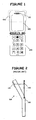
- Figure 1 is an illustration of a typical flip type mobile phone 100 showing an outline of a near field scan area 130 in the top-flip around a speaker 110 and partially encompassing the mobile phone's display 120. This is the area of greatest concern since it is the point at which a user with a hearing aid will be in closest proximity to the E-M scattering effect.
- FIG 2 is a prior art simplified side view of a flip or clamshell type mobile phone 100 illustrating an antenna 140 in the extended position.
- the antenna is coupled with an antenna feed contact 150 to establish an electrical connection with the pertinent components within the mobile phone 100.
- the speaker 110 (or speaker location) is also illustrated in this side view.
- the antenna 140 is shown in its extended position which is in the same vertical axis as the bottom flip portion of the mobile phone 100.
- the task of extending and retracting the antenna is kept simple.
- the problem with this configuration is that the actual distance (d) between the antenna and the near field scan area 130 around the speaker 110 is minimized. This is significant because this distance has an appreciable effect on the intensity of EM fields in the near field scan area 130. The smaller the distance the greater the intensity of EM fields in the near field scan area 130.
- Figure 3 is a simplified side view of a flip or clamshell type mobile phone illustrating an antenna in the extended position.
- Figure 3 is similar to Figure 2 except that antenna 140 extends outward at an angle that is not in the same vertical axis as the bottom flip portion of the mobile phone 100.
- the antenna 140 extends outward from the bottom flip portion of the mobile phone 100 such that it forms a tilt angle ( ⁇ ) with the top flip portion of the mobile phone 100 that is greater than the angle formed had the antenna extended in the same vertical axis as the bottom flip portion of the mobile phone 100.
- Tilt angle ( ⁇ ) in Figure 3 creates more separation (D) between the antenna 140 and the near field scan area 130 around the speaker 110.
- the distance (D) in Figure 3 is greater than the distance (d) in Figure 2 .
- the tilt angle is one aspect of the present invention that reduces the intensity of EM fields in the near field scan area 130.
- Another aspect involves the choice of antenna type.
- the antenna type is chosen such that ground current flowing on the printed circuit board (PCB) is minimized.
- PCB printed circuit board
- a halfwave antenna exhibits such a behavior.
- These types of antenna include a halfwave monopole and a halfwave top-loaded monopole.
- an antenna matching network 400 has been included for two purposes.
- the first purpose is to tune the antenna 140 to the frequencies of interest.
- the antenna 140 is designed to operate in all four GSM bands (850 MHz, 900 MHz, 1800 MHz, and 1900 MHz).
- the second purpose is to use the antenna matching network 400 to attenuate the output power if the antenna tilt angle ( ⁇ ) previously discussed cannot be made large enough to meet HAC requirements.
- the antenna matching network 400 can be designed to further attenuate output power when necessary while not attenuating the power at operating bands that do not need any. Based on the discrete component values given in the example of Figure 4 , the antenna matching network 400 attenuates the 850-MHz band while it does not attenuate the 1800 MHz and 1900 MHz.
- the antenna matching network 400 is a relatively simple circuit comprised of an inductor 420 coupled on one end with the antenna 140.
- a second inductor 430 is coupled (shunted) to ground on one end and between the first inductor 420 and a capacitor 440 on the other end.
- the capacitor is also coupled with the antenna feed contact 150.
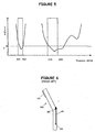
- FIG 5 illustrates the voltage standing wave ratio (VSWR) values across the GSM operating bands of interest for the antenna 140 in the extended position as illustrated in Figure 3 .
- Results were measured with the antenna 140 in the extended position using a clamshell-phone prototype with a tilt angle ( ⁇ ) of 37° between the top flip portion of the mobile phone 100 and the antenna 140.
- the antenna 140 is a halfwave top-loaded monopole composed of a straight monopole of 85 mm long loaded with a helical part of 9.5 mm height, 6 mm diameter, and 2.5 mm pitch separation.
- the antenna matching circuit is of a T-network type configuration with discrete component values shown in Figure 4 .
- VSWR is a figure of merit to show the antenna impedance match to RF front end of the mobile phone.
- a VSWR equal to 1 is a perfect match and no mismatch loss occurs.
- a VSWR of 3 or less is generally a good VSWR value.
- the antenna configuration illustrated in Figure 3 is capable of operating in all four GSM frequency bands, 850 MHz, 900 MHz, 1800 MHz, and 1900 MHz bands in the extended position.
- TRP total radiated power
- Table 3 summarizes the results for the antenna in the extended position. Values for HAC evaluation in the table represent the margin value in dB in compliance with the required M3 rating. Since mobile phone conducted power was calibrated at 32 dBm for 850 MHz and 900 MHz bands and 30.0 dBm for 1800 MHz and 1900 MHz bands, antenna total efficiency can be computed, as shown in Table 3.
- Table 3 illustrates that a clamshell or flip type mobile phone using the extended antenna configuration of the present invention is in compliance with HAC requirements according to the M3 rating in all the US operating bands while still maintaining good radiated performance.
- FIG. 6 is a prior art simplified side view of a flip or clamshell type mobile phone 100 illustrating an antenna 140 in the retracted position.
- the antenna 140 is retracted within the mobile phone 100 such that the top end is in contact with the antenna feed contact 150 and the bottom end is in contact with a ground contact 160.
- FIG 7 is a simplified side view of a flip or clamshell type mobile phone 100 illustrating an antenna 140 in the retracted position according to an embodiment of the present invention.
- Figure 7 is similar to Figure 6 except that antenna 140 contacts the ground contact 160 at a different location when retracted.
- the antenna 140 When the antenna 140 is in the retracted position the antenna 140 is not in direct contact with the antenna feed contact 150. In this case, the feeding mechanism is achieved through a coupling effect from the antenna feed contact 150 to the antenna 140.
- a part of the antenna 140 located a certain distance x from its bottom tip is contacting directly to ground 160. This permits the antenna to operate effectively in the 850-MHz band. Without the ground contact 160 positioned as it is when the antenna 140 is in the retracted position, the mobile phone 100 would not perform well in the 850-MHz band.
- a top-loaded halfwave monopole antenna is capacitively fed (non-contact feeding) at the bottom of its helical stub.
- a matching network can be added to the antenna feed to tune the antenna operating frequency and/or attenuate output power if needed.
- a key characteristic of this embodiment is the grounding of the antenna at distance x from its bottom tip as opposed to grounding the antenna at its bottom tip. By varying x, the frequency tuning in the low-band can be controlled.
- a matching circuit like that in Figure 4 can be included between the antenna contact to ground 160 and the ground for finer frequency tuning.
- Figure 8 illustrates the VSWR values across the GSM operating bands of interest for the antenna 140 in the retracted position as illustrated in Figure 7 .
- results were measured for an antenna ground contact 160 that touches the antenna 140 at 19mm from the antenna bottom tip.
- the antenna 140 is a halfwave top-loaded monopole composed of a straight monopole of 85 mm long loaded with a helical part of 9.5 mm height, 6 mm diameter, and 2.5 mm pitch separation.
- the antenna matching circuit is of a T-network type configuration with discrete component values shown in Figure 4 .
- the antenna configuration illustrated in Figure 7 is capable of operating in all four GSM frequency bands, 850 MHz, 900 MHz, 1800 MHz, and 1900 MHz bands in the retracted position.
- Table 4 summarizes the results for the antenna in the retracted position. Values for HAC evaluation in the table represent the margin value in dB in compliance with the required M3 rating. Since mobile phone conducted power was calibrated at 32 dBm for 850 MHz and 900 MHz bands and 30.0 dBm for 1800 MHz and 1900 MHz bands, antenna total efficiency can be computed, as shown in Table 4.
- TABLE 4 Retracted Antenna Position 850 MHz 900 MHz 1800 MHz 1900 MHz TRP (dBm) 27.8 23.3 24.2 23.5 Antenna Total Efficiency (dB) - 4.2 - 8.7 - 5.8 - 6.5 HAC M3 Compliance Margin (dB) 4.1 7.6
- Table 4 illustrates that a clamshell or flip type mobile phone using the retracted antenna configuration of the present invention is in compliance with HAC requirements according to the M3 rating in all the US operating bands while still maintaining good radiated performance.
Landscapes
- Engineering & Computer Science (AREA)
- Computer Networks & Wireless Communication (AREA)
- Signal Processing (AREA)
- Support Of Aerials (AREA)
- Details Of Aerials (AREA)
- Telephone Set Structure (AREA)
- Details Of Audible-Bandwidth Transducers (AREA)
- Transceivers (AREA)
- Telephone Function (AREA)
Abstract
Description
- In general, a hearing aid operates by using a microphone to pick up sound waves in the air and convert the sound waves to electrical signals. The signals are then amplified as needed and converted back to audible sounds for the user to hear. The hearing aid microphone, however, does not always work well in conjunction with audio devices like mobile phone handsets. The acoustic connection made between the audio device and the hearing aid can be poor and can create distortions in the sound. In addition, the surrounding noise in the area of the user is often picked up by the hearing aid and interferes with the desired audio.
- Mobile phones are often incompatible with many hearing aids due to the potential for radio frequency (RF) interference in the form of scattered EM fields generated by the mobile phone while in use. When a mobile phone is in communication with its network, an electromagnetic field is present around the mobile phone antenna. When the mobile phone is in use this field pulses. It is this pulsing energy that may be picked up by the hearing aid's microphone or telecoil circuitry and heard as a buzzing sound (i.e., interference) through the hearing aid.
-
US 2006/0009156 A1 discloses a mobile phone with improved hearing aid compatibility.US 6147651 ,EP 10 69 641 andDE 19639642 relate to extendable mobile phone antennas of the prior art. - To address this situation the United States Federal Communications Commission (FCC) has promulgated hearing aid compatibility (HAC) rules to minimize the interference between a mobile handset and a hearing aid. As of September 16, 2005 mobile phone handset makers are to include at least 4 or 25% of their mobile phone handset offerings that meet or exceed the ANSI (American National's Standard Institute) hearing aid compatibility (HAC) standard.
- The FCC defines HAC for mobile phones in terms of two parameters; radio-frequency (RF) emissions (M-scale) and telecoil coupling (T-scale). Mobile phones that comply with the FCC's hearing aid compatibility rule must receive a minimum rating of M3 for RF emissions and T3 for telecoil coupling. The FCC requires that nationwide carriers offer a range of phones that comply with HAC regulations beginning in September 2005 for microphone (M) mode and in September 2006 for (T) telecoil mode.
- As part of hearing aid compatibility (HAC) assessment, near-field components of electromagnetic fields are measured. These components comprise electric and magnetic fields. Tables 1 and 2 illustrate the electric and magnetic field M ratings for the FCC HAC standards.
TABLE 1 - M Ratings for HAC in standard units Category E-Field Emission Limits (V/m) H-Field Emission Limits (A/m) M1 149.6-266.1 0.45-0.8 M2 84.1-149.6 0.25-0.45 M3 47.3-84.1 0.15-0.25 M4 < 47.3 < 0.15 TABLE 2 - M Ratings for HAC converted to dB values Category E-Field Emission Limits (dBV/m) H-Field Emission Limits (dBA/m) M1 43.5-48.5 -6.9--1.9 M2 38.5-43.5 -11.9--6.9 M3 33.5-38.5 -16.9--11.9 M4 < 33.5 < -16.9 - Handsets that receive a hearing aid compatibility rating of M3 or M4 have met or surpassed the ANSI hearing aid compatibility standard as adopted by the Federal Communications Commission. An M3-rating indicates the mobile phone has satisfied the ANSI standard. An M4-rating indicates the mobile phone has exceeded the ANSI standard. The higher the M-rating the mobile phone has the lower the radio frequency (RF) emissions level and higher signal quality the mobile phone will have to the hearing aid device, assuming that the phone is still performing efficiently.
- "T" rating refers to a mobile phone's coupling ability and is intended for use with hearing aids in the telecoil mode. The higher the "T" number the more likely you will be able to use your phone with your hearing aid in telecoil mode. The FCC regulations require that cell phones be manufactured for use with hearing aids on telecoil setting by September 2006. For purposes of the present invention, however, only the M rating aspect of HAC is addressed.
- For a phone to be HAC compliant, it must be compliant in all US frequency bands of operation for mobile phones. These include the 850-MHz and 1900-MHz bands. Moreover, the mobile phones must, in these operating bands, exhibit, at a minimum, an M3 rating meaning RF emissions from a digital wireless mobile phone are not to exceed -11.9 dB A/m for H-field and 38.6 dB V/m for E-field.
To the inventor's best knowledge, there has not been any mobile phone that meets the M3 rating concurrently in the 850-MHz and 1900-MHz frequency bands of operation. - The invention is defined in the appended claims.
- According to an embodiment of the present invention, there is a flip type mobile phone that includes a speaker component near the top end of the upper flip portion of the mobile phone and an extendable antenna configuration in a retracted position. The antenna configuration is designed to reduce, to a hearing aid compatibility (HAC) M3 rating or better, any scattered EM field effects that can cause interference to an active hearing aid when the flip type mobile phone is operated in relatively close proximity to the active hearing aid. The antenna configuration comprises a halfwave type antenna retractable into the lower flip portion of the mobile phone. An antenna feed contact is not in direct contact with the antenna in the retracted position. The antenna is capacitively fed via a coupling effect that is achieved between the antenna and the antenna feed contact. An antenna ground contact positioned a distance, x, up from the bottom tip of the antenna and contacting the antenna when in the retracted position. The distance x is determined based on the tuning requirements of the antenna configuration to maximize efficiency in the 850 MHZ GSM frequency band. An antenna matching circuit is coupled between the antenna ground contact and the ground for finer frequency tuning.
- An antenna matching network coupled between the antenna feed contact and the antenna can also be included. The antenna matching network is for tuning the antenna configuration to operate in the 850 MHZ, 900 MHz, 1800 MHZ, and 1900 MHz GSM frequency bands. The antenna matching network also attenuates the antenna configuration based on the values of its discrete components to further maximize antenna performance operate in the 850 MHZ, 900 MHz, 1800 MHZ, and 1900 MHz GSM frequency bands.
-
-
Figure 1 is an illustration of a typical flip or clamshell type mobile phone showing an outline of a near field scan area where electromagnetic (EM) fields emanating from the mobile phone are most problematic. -
Figure 2 is a prior art simplified side view of a flip or clamshell type mobile phone illustrating an antenna in the extended position. -
Figure 3 is a simplified side view of a flip or clamshell type mobile phone illustrating an antenna in the extended position. -
Figure 4 is an antenna matching network for use with the antenna illustrated infigure 2 .Figure 5 is a graph illustrating the voltage standing wave ratio (VSWR) for the antenna illustrated infigure 2 when the mobile phone is in operation. -
Figure 6 is a prior art simplified side view of a flip or clamshell type mobile phone illustrating an antenna in the retracted position. -
Figure 7 is a simplified side view of a flip or clamshell type mobile phone illustrating an antenna in the retracted position according to an embodiment of the present invention. -
Figure 8 is a graph illustrating the voltage standing wave ratio (VSWR) for the antenna illustrated infigure 7 when the mobile phone is in operation. - The present invention discloses an antenna system or configuration for a mobile phone that reduces the scattered EM field effects to hearing aids. Specifically, the present invention is designed to meet the United States Federal Communications Commission (FCC) RF emission minimum rating of M3.
- Noise in a hearing aid device is generated by electromagnetic (EM) fields emanating from the mobile phone. These EM fields come directly from the antenna and from the fields generated due to the induced ground current flowing in the PCB of the mobile phone. In the lower 850 MHz frequency band this ground current can be strong, creating strong fields propagating toward the hearing aid device.
-
Figure 1 is an illustration of a typical flip typemobile phone 100 showing an outline of a nearfield scan area 130 in the top-flip around aspeaker 110 and partially encompassing the mobile phone'sdisplay 120. This is the area of greatest concern since it is the point at which a user with a hearing aid will be in closest proximity to the E-M scattering effect. -
Figure 2 is a prior art simplified side view of a flip or clamshell typemobile phone 100 illustrating anantenna 140 in the extended position. The antenna is coupled with anantenna feed contact 150 to establish an electrical connection with the pertinent components within themobile phone 100. The speaker 110 (or speaker location) is also illustrated in this side view. Theantenna 140 is shown in its extended position which is in the same vertical axis as the bottom flip portion of themobile phone 100. By keeping theantenna 140 in the same vertical axis as the bottom flip portion of themobile phone 100, the task of extending and retracting the antenna is kept simple. The problem with this configuration, however, is that the actual distance (d) between the antenna and the nearfield scan area 130 around thespeaker 110 is minimized. This is significant because this distance has an appreciable effect on the intensity of EM fields in the nearfield scan area 130. The smaller the distance the greater the intensity of EM fields in the nearfield scan area 130. -
Figure 3 is a simplified side view of a flip or clamshell type mobile phone illustrating an antenna in the extended position.Figure 3 is similar toFigure 2 except thatantenna 140 extends outward at an angle that is not in the same vertical axis as the bottom flip portion of themobile phone 100. Theantenna 140 extends outward from the bottom flip portion of themobile phone 100 such that it forms a tilt angle (α) with the top flip portion of themobile phone 100 that is greater than the angle formed had the antenna extended in the same vertical axis as the bottom flip portion of themobile phone 100. Tilt angle (α) inFigure 3 creates more separation (D) between theantenna 140 and the nearfield scan area 130 around thespeaker 110. The distance (D) inFigure 3 is greater than the distance (d) inFigure 2 . - The tilt angle is one aspect of the present invention that reduces the intensity of EM fields in the near
field scan area 130. Another aspect involves the choice of antenna type. The antenna type is chosen such that ground current flowing on the printed circuit board (PCB) is minimized. A halfwave antenna exhibits such a behavior. These types of antenna include a halfwave monopole and a halfwave top-loaded monopole. - In addition, an
antenna matching network 400 has been included for two purposes. The first purpose is to tune theantenna 140 to the frequencies of interest. In this case, theantenna 140 is designed to operate in all four GSM bands (850 MHz, 900 MHz, 1800 MHz, and 1900 MHz). The second purpose is to use theantenna matching network 400 to attenuate the output power if the antenna tilt angle (α) previously discussed cannot be made large enough to meet HAC requirements. Theantenna matching network 400 can be designed to further attenuate output power when necessary while not attenuating the power at operating bands that do not need any. Based on the discrete component values given in the example ofFigure 4 , theantenna matching network 400 attenuates the 850-MHz band while it does not attenuate the 1800 MHz and 1900 MHz. Theantenna matching network 400 is a relatively simple circuit comprised of aninductor 420 coupled on one end with theantenna 140. Asecond inductor 430 is coupled (shunted) to ground on one end and between thefirst inductor 420 and acapacitor 440 on the other end. The capacitor is also coupled with theantenna feed contact 150. -
Figure 5 illustrates the voltage standing wave ratio (VSWR) values across the GSM operating bands of interest for theantenna 140 in the extended position as illustrated inFigure 3 . Results were measured with theantenna 140 in the extended position using a clamshell-phone prototype with a tilt angle (α) of 37° between the top flip portion of themobile phone 100 and theantenna 140. Theantenna 140 is a halfwave top-loaded monopole composed of a straight monopole of 85 mm long loaded with a helical part of 9.5 mm height, 6 mm diameter, and 2.5 mm pitch separation. The antenna matching circuit is of a T-network type configuration with discrete component values shown inFigure 4 . - VSWR is a figure of merit to show the antenna impedance match to RF front end of the mobile phone. A VSWR equal to 1 is a perfect match and no mismatch loss occurs. A VSWR of 3 or less is generally a good VSWR value. According to the graph in
Figure 5 , the antenna configuration illustrated inFigure 3 is capable of operating in all four GSM frequency bands, 850 MHz, 900 MHz, 1800 MHz, and 1900 MHz bands in the extended position. - Measurements of electromagnetic fields on the prototype mobile phone having an antenna configuration as described herein to evaluate HAC performance were done according a measurement procedure in compliance with the specifications outlined by the FCC. In order the show that the phone has good radiated performance, total radiated power (TRP) was also measured in free-space environment at all the GSM bands.
- Table 3 summarizes the results for the antenna in the extended position. Values for HAC evaluation in the table represent the margin value in dB in compliance with the required M3 rating. Since mobile phone conducted power was calibrated at 32 dBm for 850 MHz and 900 MHz bands and 30.0 dBm for 1800 MHz and 1900 MHz bands, antenna total efficiency can be computed, as shown in Table 3.
TABLE 3 Extended Antenna Position 850 MHz 900 MHz 1800 MHz 1900 MHz TRP (dBm) 28.7 27.3 24.8 25.3 Antenna Total Efficiency (dB) - 3.3 - 4.7 - 5.2 - 4.7 HAC M3 Compliance Margin (dB) 1.0 3.2 - Table 3 illustrates that a clamshell or flip type mobile phone using the extended antenna configuration of the present invention is in compliance with HAC requirements according to the M3 rating in all the US operating bands while still maintaining good radiated performance.
-
Figure 6 is a prior art simplified side view of a flip or clamshell typemobile phone 100 illustrating anantenna 140 in the retracted position. Theantenna 140 is retracted within themobile phone 100 such that the top end is in contact with theantenna feed contact 150 and the bottom end is in contact with aground contact 160. -
Figure 7 is a simplified side view of a flip or clamshell typemobile phone 100 illustrating anantenna 140 in the retracted position according to an embodiment of the present invention.Figure 7 is similar toFigure 6 except thatantenna 140 contacts theground contact 160 at a different location when retracted. When theantenna 140 is in the retracted position theantenna 140 is not in direct contact with theantenna feed contact 150. In this case, the feeding mechanism is achieved through a coupling effect from theantenna feed contact 150 to theantenna 140. Additionally in the retracted position, a part of theantenna 140 located a certain distance x from its bottom tip is contacting directly toground 160. This permits the antenna to operate effectively in the 850-MHz band. Without theground contact 160 positioned as it is when theantenna 140 is in the retracted position, themobile phone 100 would not perform well in the 850-MHz band. - This configuration can be used to meet HAC M3 requirement when used in the retracted position. A top-loaded halfwave monopole antenna is capacitively fed (non-contact feeding) at the bottom of its helical stub. Like the antenna in the extended position, a matching network can be added to the antenna feed to tune the antenna operating frequency and/or attenuate output power if needed. A key characteristic of this embodiment is the grounding of the antenna at distance x from its bottom tip as opposed to grounding the antenna at its bottom tip. By varying x, the frequency tuning in the low-band can be controlled. Furthermore, a matching circuit like that in
Figure 4 can be included between the antenna contact to ground 160 and the ground for finer frequency tuning. -
Figure 8 illustrates the VSWR values across the GSM operating bands of interest for theantenna 140 in the retracted position as illustrated inFigure 7 . With theantenna 140 in the retracted position, results were measured for anantenna ground contact 160 that touches theantenna 140 at 19mm from the antenna bottom tip. - Just as in the extended scenario, the
antenna 140 is a halfwave top-loaded monopole composed of a straight monopole of 85 mm long loaded with a helical part of 9.5 mm height, 6 mm diameter, and 2.5 mm pitch separation. The antenna matching circuit is of a T-network type configuration with discrete component values shown inFigure 4 . - According to the graph in
Figure 8 , the antenna configuration illustrated inFigure 7 is capable of operating in all four GSM frequency bands, 850 MHz, 900 MHz, 1800 MHz, and 1900 MHz bands in the retracted position. - Table 4 summarizes the results for the antenna in the retracted position. Values for HAC evaluation in the table represent the margin value in dB in compliance with the required M3 rating. Since mobile phone conducted power was calibrated at 32 dBm for 850 MHz and 900 MHz bands and 30.0 dBm for 1800 MHz and 1900 MHz bands, antenna total efficiency can be computed, as shown in Table 4.
TABLE 4 Retracted Antenna Position 850 MHz 900 MHz 1800 MHz 1900 MHz TRP (dBm) 27.8 23.3 24.2 23.5 Antenna Total Efficiency (dB) - 4.2 - 8.7 - 5.8 - 6.5 HAC M3 Compliance Margin (dB) 4.1 7.6 - Table 4 illustrates that a clamshell or flip type mobile phone using the retracted antenna configuration of the present invention is in compliance with HAC requirements according to the M3 rating in all the US operating bands while still maintaining good radiated performance.
- The terminology used herein is for the purpose of describing particular embodiments only and is not intended to be limiting of the invention. As used herein, the singular forms "a", "an" and "the" are intended to include the plural forms as well, unless the context clearly indicates otherwise. It will be further understood that the terms "comprises" and/or "comprising," when used in this specification, specify the presence of stated features, integers, steps, operations, elements, and/or components, but do not preclude the presence or addition of one or more other features, integers, steps, operations, elements, components, and/or groups thereof.
- Although specific embodiments have been illustrated and described herein, those of ordinary skill in the art appreciate that any arrangement which is calculated to achieve the same purpose may be substituted for the specific embodiments shown and that the invention has other applications in other environments. This application is intended to cover any adaptations or variations of the present invention. The following claims are in no way intended to limit the scope of the invention to the specific embodiments described herein.
Claims (4)
- A flip type mobile phone [100] comprising
an upper flip portion and lower flip portion,
a speaker component [100] near the top end of the upper flip portion and
an extendable antenna configuration in a retracted position, the antenna configuration designed to reduce, to a hearing aid compatibility (HAC) M3 rating or better, scattered EM field effects that can cause interference to an active hearing aid
when the flip type mobile phone [100] is operated in relatively close proximity to the active hearing aid, the antenna configuration comprising:a halfwave type antenna [140] retractable into the lower flip portion of the mobile phone;an antenna feed contact [150] that is not in direct contact with the antenna [140] in the retracted positionwherein the antenna [140] is capacitively fed via a coupling effect that is achieved between the antenna [140] and the antenna feed contact [150]; andan antenna ground contact [160] positioned a distance, x, up from the bottom tip of the antenna [140] and contacting the antenna [140] when in the retracted position; andan antenna matching circuit [400] coupled between the antenna ground contact [160] and the ground, for finer frequency tuning. - The flip type mobile phone of claim 1, wherein the distance x is determined based on the tuning requirements of the antenna configuration to maximize efficiency in the 850 MHz GSM frequency band.
- The flip type mobile phone of claim 2, further comprising an antenna matching circuit [400] coupled between the antenna feed contact [150] and the antenna [140], the antenna matching circuit [400] for tuning the antenna configuration to operate in the 850 MHz, 900 MHz, 1800 MHz, and 1900 MHz GSM frequency bands.
- The flip type mobile phone of claim 3, wherein the antenna matching circuit [400] coupled between the antenna feed contact [150] and the antenna (140) also attenuates the output power based on the values of its discrete components to further maximize antenna performance to operate in the 850 MHz, 900 MHz, 1800 MHz, and 1900 MHz GSM frequency bands.
Applications Claiming Priority (2)
| Application Number | Priority Date | Filing Date | Title |
|---|---|---|---|
| US11/307,927 US7342545B2 (en) | 2006-02-28 | 2006-02-28 | Antenna system configuration for mobile phones |
| PCT/US2006/060029 WO2007100380A1 (en) | 2006-02-28 | 2006-10-17 | Antenna system configuration for mobile phones |
Publications (3)
| Publication Number | Publication Date |
|---|---|
| EP1989758A1 EP1989758A1 (en) | 2008-11-12 |
| EP1989758B1 true EP1989758B1 (en) | 2011-03-16 |
| EP1989758B8 EP1989758B8 (en) | 2012-03-21 |
Family
ID=37781791
Family Applications (1)
| Application Number | Title | Priority Date | Filing Date |
|---|---|---|---|
| EP06839451A Ceased EP1989758B8 (en) | 2006-02-28 | 2006-10-17 | Antenna system configuration for mobile phones |
Country Status (6)
| Country | Link |
|---|---|
| US (1) | US7342545B2 (en) |
| EP (1) | EP1989758B8 (en) |
| JP (2) | JP2009528772A (en) |
| CN (1) | CN101390252A (en) |
| DE (1) | DE602006020784D1 (en) |
| WO (1) | WO2007100380A1 (en) |
Families Citing this family (15)
| Publication number | Priority date | Publication date | Assignee | Title |
|---|---|---|---|---|
| US7184800B2 (en) * | 2002-10-15 | 2007-02-27 | Kyocera Wireless Corp. | Printed stubby unbalanced dipole antenna |
| EP2151890A1 (en) * | 2008-08-07 | 2010-02-10 | Laird Technologies AB | Antenna arrangement for a portable radio communication device, and portable radio communication device comprising such an antenna arrangement |
| TWI358852B (en) | 2008-09-03 | 2012-02-21 | Htc Corp | Handset device |
| TWI400928B (en) * | 2009-07-21 | 2013-07-01 | Htc Corp | Mobile device |
| US8477069B2 (en) * | 2009-08-21 | 2013-07-02 | Mediatek Inc,. | Portable electronic device and antenna thereof |
| US8847833B2 (en) * | 2009-12-29 | 2014-09-30 | Pulse Finland Oy | Loop resonator apparatus and methods for enhanced field control |
| TWI423522B (en) * | 2010-02-01 | 2014-01-11 | Compal Communications Inc | Handheld electronic device |
| CN102137176A (en) * | 2011-03-22 | 2011-07-27 | 惠州Tcl移动通信有限公司 | Mobile phone |
| US10631109B2 (en) | 2017-09-28 | 2020-04-21 | Starkey Laboratories, Inc. | Ear-worn electronic device incorporating antenna with reactively loaded network circuit |
| CN110323548B (en) * | 2018-03-31 | 2020-12-22 | Oppo广东移动通信有限公司 | electronic device |
| US10979828B2 (en) | 2018-06-05 | 2021-04-13 | Starkey Laboratories, Inc. | Ear-worn electronic device incorporating chip antenna loading of antenna structure |
| US10785582B2 (en) | 2018-12-10 | 2020-09-22 | Starkey Laboratories, Inc. | Ear-worn electronic hearing device incorporating an antenna with cutouts |
| US11902748B2 (en) | 2018-08-07 | 2024-02-13 | Starkey Laboratories, Inc. | Ear-worn electronic hearing device incorporating an antenna with cutouts |
| US10951997B2 (en) | 2018-08-07 | 2021-03-16 | Starkey Laboratories, Inc. | Hearing device incorporating antenna arrangement with slot radiating element |
| US10931005B2 (en) | 2018-10-29 | 2021-02-23 | Starkey Laboratories, Inc. | Hearing device incorporating a primary antenna in conjunction with a chip antenna |
Family Cites Families (20)
| Publication number | Priority date | Publication date | Assignee | Title |
|---|---|---|---|---|
| US3147651A (en) * | 1962-10-18 | 1964-09-08 | Seigford Robert | Hand tool tubing bender |
| US5467096A (en) | 1993-02-25 | 1995-11-14 | Nec Corporation | Antenna for a radio communication apparatus |
| US5926748A (en) * | 1993-07-23 | 1999-07-20 | Nec Corporation | Portable radio apparatus capable of keeping antenna away from user when calling |
| JP3674172B2 (en) * | 1995-09-22 | 2005-07-20 | 三菱電機株式会社 | Antenna device |
| US5812093A (en) * | 1995-09-29 | 1998-09-22 | Motorola, Inc. | Antenna assembly for a wireless-communication device |
| EP1353400A3 (en) | 1996-09-11 | 2003-11-19 | Matsushita Electric Industrial Co., Ltd. | Antenna system |
| JPH10190328A (en) * | 1996-10-23 | 1998-07-21 | Matsushita Electric Ind Co Ltd | Antenna device |
| US6034639A (en) * | 1997-12-22 | 2000-03-07 | T & M Antennas | Retractable antenna for portable communicator |
| KR100326224B1 (en) * | 1998-02-27 | 2002-02-27 | 비센트 비.인그라시아, 알크 엠 아헨 | An antenna adapted to operate in a plurality of frequency bands |
| US6272356B1 (en) * | 1999-05-10 | 2001-08-07 | Ericsson Inc. | Mechanical spring antenna and radiotelephones incorporating same |
| JP2001223514A (en) * | 2000-02-09 | 2001-08-17 | Sony Corp | Portable communication device, antenna directivity control method, and antenna transmission power control method |
| JP2001257514A (en) | 2000-03-09 | 2001-09-21 | Kyocera Corp | Portable radio |
| FR2815200B1 (en) * | 2000-10-09 | 2003-02-07 | Cit Alcatel | DEVICE AND METHOD FOR CONTROLLING AND CONTROLLING THE SIGNAL POWER OF A RADIO COMMUNICATION TERMINAL |
| JP4071452B2 (en) * | 2001-04-13 | 2008-04-02 | 松下電器産業株式会社 | Portable radio |
| KR100449436B1 (en) * | 2001-10-31 | 2004-09-21 | 주식회사 어필텔레콤 | Antenna device of wireless phone |
| US6563467B1 (en) * | 2001-12-28 | 2003-05-13 | Motorola, Inc. | Efficient antenna pattern shaping structure and associated radio circuitry and antenna |
| JP2003347959A (en) * | 2002-05-28 | 2003-12-05 | Sanyo Electric Co Ltd | Mobile phone |
| US6975273B1 (en) * | 2003-06-17 | 2005-12-13 | Samsung Electronics Co., Ltd. | Antenna with camera lens assembly for portable radiotelephone |
| JP3839001B2 (en) | 2003-07-28 | 2006-11-01 | 埼玉日本電気株式会社 | Portable radio |
| US8095073B2 (en) * | 2004-06-22 | 2012-01-10 | Sony Ericsson Mobile Communications Ab | Method and apparatus for improved mobile station and hearing aid compatibility |
-
2006
- 2006-02-28 US US11/307,927 patent/US7342545B2/en not_active Expired - Fee Related
- 2006-10-17 CN CNA2006800535486A patent/CN101390252A/en active Pending
- 2006-10-17 WO PCT/US2006/060029 patent/WO2007100380A1/en not_active Ceased
- 2006-10-17 JP JP2008557256A patent/JP2009528772A/en active Pending
- 2006-10-17 EP EP06839451A patent/EP1989758B8/en not_active Ceased
- 2006-11-08 DE DE602006020784T patent/DE602006020784D1/en active Active
-
2011
- 2011-12-16 JP JP2011276094A patent/JP5425878B2/en not_active Expired - Fee Related
Also Published As
| Publication number | Publication date |
|---|---|
| CN101390252A (en) | 2009-03-18 |
| JP5425878B2 (en) | 2014-02-26 |
| EP1989758B8 (en) | 2012-03-21 |
| EP1989758A1 (en) | 2008-11-12 |
| US7342545B2 (en) | 2008-03-11 |
| JP2012105301A (en) | 2012-05-31 |
| US20070200772A1 (en) | 2007-08-30 |
| DE602006020784D1 (en) | 2011-04-28 |
| WO2007100380A1 (en) | 2007-09-07 |
| JP2009528772A (en) | 2009-08-06 |
Similar Documents
| Publication | Publication Date | Title |
|---|---|---|
| JP5425878B2 (en) | Antenna system configuration for mobile phones | |
| US7911405B2 (en) | Multi-band low profile antenna with low band differential mode | |
| US6417816B2 (en) | Dual band bowtie/meander antenna | |
| EP1271690B1 (en) | An antenna | |
| US6667718B2 (en) | Microstrip dual band antenna | |
| CN102804487B (en) | Device for wireless communication including loop antenna | |
| EP2290742B1 (en) | Handheld device | |
| KR20020027636A (en) | Antenna arrangement and portable radio communication device | |
| KR20010075231A (en) | Capacitively-tune broadband antenna structure | |
| JP2002151949A (en) | Portable terminal | |
| US8115682B2 (en) | Multi-band HAC compatible antenna module | |
| US20110018770A1 (en) | Built-in straight mobile antenna type dual band antenna assembly with improved hac performance | |
| US7042414B1 (en) | Ultra wideband internal antenna | |
| EP1360738B1 (en) | Antenna device and method of adjusting said antenna device | |
| CN108432048B (en) | Slot antenna and terminal | |
| WO2020044212A1 (en) | Increasing bandwidth of a dipole antenna | |
| EP1969033A2 (en) | Siloxane prepolymer containing pendant cationic and polymerizable groups | |
| EP3514886B1 (en) | Conductive plane antenna | |
| CN101542828A (en) | Antenna device and portable radio communication device comprising such antenna device | |
| US20100026580A1 (en) | PIFA antenna design method | |
| US9093746B2 (en) | Wireless communication device having metal assembly and conductive assembly for reducing specific absorption rate (SAR) | |
| CN113571869B (en) | Antenna structure | |
| KR101110568B1 (en) | Mobile communication terminal | |
| CN113540763A (en) | Antenna and equipment | |
| JP3267871B2 (en) | Antenna device |
Legal Events
| Date | Code | Title | Description |
|---|---|---|---|
| PUAI | Public reference made under article 153(3) epc to a published international application that has entered the european phase |
Free format text: ORIGINAL CODE: 0009012 |
|
| 17P | Request for examination filed |
Effective date: 20080814 |
|
| AK | Designated contracting states |
Kind code of ref document: A1 Designated state(s): DE FR GB |
|
| 17Q | First examination report despatched |
Effective date: 20090115 |
|
| RBV | Designated contracting states (corrected) |
Designated state(s): DE FR GB |
|
| GRAP | Despatch of communication of intention to grant a patent |
Free format text: ORIGINAL CODE: EPIDOSNIGR1 |
|
| GRAS | Grant fee paid |
Free format text: ORIGINAL CODE: EPIDOSNIGR3 |
|
| GRAA | (expected) grant |
Free format text: ORIGINAL CODE: 0009210 |
|
| AK | Designated contracting states |
Kind code of ref document: B1 Designated state(s): DE FR GB |
|
| REG | Reference to a national code |
Ref country code: GB Ref legal event code: FG4D |
|
| REF | Corresponds to: |
Ref document number: 602006020784 Country of ref document: DE Date of ref document: 20110428 Kind code of ref document: P |
|
| REG | Reference to a national code |
Ref country code: DE Ref legal event code: R096 Ref document number: 602006020784 Country of ref document: DE Effective date: 20110428 |
|
| PLBE | No opposition filed within time limit |
Free format text: ORIGINAL CODE: 0009261 |
|
| STAA | Information on the status of an ep patent application or granted ep patent |
Free format text: STATUS: NO OPPOSITION FILED WITHIN TIME LIMIT |
|
| 26N | No opposition filed |
Effective date: 20111219 |
|
| REG | Reference to a national code |
Ref country code: DE Ref legal event code: R097 Ref document number: 602006020784 Country of ref document: DE Effective date: 20111219 |
|
| REG | Reference to a national code |
Ref country code: DE Ref legal event code: R082 Ref document number: 602006020784 Country of ref document: DE Representative=s name: ISARPATENT PATENTANWAELTE BEHNISCH, BARTH, CHA, DE Ref country code: DE Ref legal event code: R081 Ref document number: 602006020784 Country of ref document: DE Owner name: SONY MOBILE COMMUNICATIONS AB, SE Free format text: FORMER OWNER: SONY ERICSSON MOBILE COMMUNICATIONS AB, LUND, SE Ref country code: DE Ref legal event code: R081 Ref document number: 602006020784 Country of ref document: DE Owner name: SNAPTRACK, INC., SAN DIEGO, US Free format text: FORMER OWNER: SONY ERICSSON MOBILE COMMUNICATIONS AB, LUND, SE Ref country code: DE Ref legal event code: R082 Ref document number: 602006020784 Country of ref document: DE Representative=s name: ISARPATENT - PATENTANWAELTE- UND RECHTSANWAELT, DE |
|
| REG | Reference to a national code |
Ref country code: FR Ref legal event code: PLFP Year of fee payment: 10 |
|
| REG | Reference to a national code |
Ref country code: FR Ref legal event code: CD Owner name: SONY MOBILE COMMUNICATIONS AB Effective date: 20151026 |
|
| REG | Reference to a national code |
Ref country code: DE Ref legal event code: R082 Ref document number: 602006020784 Country of ref document: DE Representative=s name: ISARPATENT - PATENT- UND RECHTSANWAELTE BEHNIS, DE Ref country code: DE Ref legal event code: R082 Ref document number: 602006020784 Country of ref document: DE Representative=s name: ISARPATENT PATENTANWAELTE BEHNISCH, BARTH, CHA, DE Ref country code: DE Ref legal event code: R082 Ref document number: 602006020784 Country of ref document: DE Representative=s name: ISARPATENT - PATENTANWAELTE- UND RECHTSANWAELT, DE Ref country code: DE Ref legal event code: R081 Ref document number: 602006020784 Country of ref document: DE Owner name: SNAPTRACK, INC., SAN DIEGO, US Free format text: FORMER OWNER: SONY MOBILE COMMUNICATIONS AB, LUND, SE |
|
| REG | Reference to a national code |
Ref country code: GB Ref legal event code: 732E Free format text: REGISTERED BETWEEN 20160714 AND 20160720 |
|
| REG | Reference to a national code |
Ref country code: FR Ref legal event code: PLFP Year of fee payment: 11 |
|
| REG | Reference to a national code |
Ref country code: FR Ref legal event code: TP Owner name: SNAPTRACK, INC., US Effective date: 20161011 |
|
| REG | Reference to a national code |
Ref country code: FR Ref legal event code: PLFP Year of fee payment: 12 |
|
| PGFP | Annual fee paid to national office [announced via postgrant information from national office to epo] |
Ref country code: GB Payment date: 20170925 Year of fee payment: 12 Ref country code: FR Payment date: 20170922 Year of fee payment: 12 |
|
| PGFP | Annual fee paid to national office [announced via postgrant information from national office to epo] |
Ref country code: DE Payment date: 20171027 Year of fee payment: 12 |
|
| REG | Reference to a national code |
Ref country code: DE Ref legal event code: R119 Ref document number: 602006020784 Country of ref document: DE |
|
| GBPC | Gb: european patent ceased through non-payment of renewal fee |
Effective date: 20181017 |
|
| PG25 | Lapsed in a contracting state [announced via postgrant information from national office to epo] |
Ref country code: DE Free format text: LAPSE BECAUSE OF NON-PAYMENT OF DUE FEES Effective date: 20190501 |
|
| PG25 | Lapsed in a contracting state [announced via postgrant information from national office to epo] |
Ref country code: FR Free format text: LAPSE BECAUSE OF NON-PAYMENT OF DUE FEES Effective date: 20181031 |
|
| PG25 | Lapsed in a contracting state [announced via postgrant information from national office to epo] |
Ref country code: GB Free format text: LAPSE BECAUSE OF NON-PAYMENT OF DUE FEES Effective date: 20181017 |