EP1989068B1 - Einzelradaufhängung mit fahrwerksversteifenden gas- oder hydraulikfederungsteilen - Google Patents
Einzelradaufhängung mit fahrwerksversteifenden gas- oder hydraulikfederungsteilen Download PDFInfo
- Publication number
- EP1989068B1 EP1989068B1 EP07722924A EP07722924A EP1989068B1 EP 1989068 B1 EP1989068 B1 EP 1989068B1 EP 07722924 A EP07722924 A EP 07722924A EP 07722924 A EP07722924 A EP 07722924A EP 1989068 B1 EP1989068 B1 EP 1989068B1
- Authority
- EP
- European Patent Office
- Prior art keywords
- semi
- arm
- top plate
- wheel suspension
- independent wheel
- Prior art date
- Legal status (The legal status is an assumption and is not a legal conclusion. Google has not performed a legal analysis and makes no representation as to the accuracy of the status listed.)
- Not-in-force
Links
- 239000000725 suspension Substances 0.000 title claims abstract description 33
- 239000006096 absorbing agent Substances 0.000 claims description 7
- 230000035939 shock Effects 0.000 claims description 7
- 238000009434 installation Methods 0.000 abstract description 2
- 238000012986 modification Methods 0.000 abstract 1
- 230000004048 modification Effects 0.000 abstract 1
- 229920001971 elastomer Polymers 0.000 description 5
- 238000005096 rolling process Methods 0.000 description 5
- 239000000872 buffer Substances 0.000 description 3
- 239000011324 bead Substances 0.000 description 2
- 238000010276 construction Methods 0.000 description 2
- 239000000806 elastomer Substances 0.000 description 2
- 210000003128 head Anatomy 0.000 description 2
- 229910001018 Cast iron Inorganic materials 0.000 description 1
- 241000237942 Conidae Species 0.000 description 1
- XEEYBQQBJWHFJM-UHFFFAOYSA-N Iron Chemical group [Fe] XEEYBQQBJWHFJM-UHFFFAOYSA-N 0.000 description 1
- 229910052782 aluminium Inorganic materials 0.000 description 1
- XAGFODPZIPBFFR-UHFFFAOYSA-N aluminium Chemical compound [Al] XAGFODPZIPBFFR-UHFFFAOYSA-N 0.000 description 1
- 238000006073 displacement reaction Methods 0.000 description 1
- 238000005553 drilling Methods 0.000 description 1
- 230000010354 integration Effects 0.000 description 1
- 238000012423 maintenance Methods 0.000 description 1
- 229910052751 metal Inorganic materials 0.000 description 1
- 239000002184 metal Substances 0.000 description 1
Images


Classifications
-
- B—PERFORMING OPERATIONS; TRANSPORTING
- B60—VEHICLES IN GENERAL
- B60G—VEHICLE SUSPENSION ARRANGEMENTS
- B60G3/00—Resilient suspensions for a single wheel
- B60G3/18—Resilient suspensions for a single wheel with two or more pivoted arms, e.g. parallelogram
- B60G3/20—Resilient suspensions for a single wheel with two or more pivoted arms, e.g. parallelogram all arms being rigid
-
- B—PERFORMING OPERATIONS; TRANSPORTING
- B60—VEHICLES IN GENERAL
- B60G—VEHICLE SUSPENSION ARRANGEMENTS
- B60G11/00—Resilient suspensions characterised by arrangement, location or kind of springs
- B60G11/26—Resilient suspensions characterised by arrangement, location or kind of springs having fluid springs only, e.g. hydropneumatic springs
- B60G11/28—Resilient suspensions characterised by arrangement, location or kind of springs having fluid springs only, e.g. hydropneumatic springs characterised by means specially adapted for attaching the spring to axle or sprung part of the vehicle
-
- B—PERFORMING OPERATIONS; TRANSPORTING
- B60—VEHICLES IN GENERAL
- B60G—VEHICLE SUSPENSION ARRANGEMENTS
- B60G7/00—Pivoted suspension arms; Accessories thereof
- B60G7/02—Attaching arms to sprung part of vehicle
-
- B—PERFORMING OPERATIONS; TRANSPORTING
- B60—VEHICLES IN GENERAL
- B60G—VEHICLE SUSPENSION ARRANGEMENTS
- B60G2200/00—Indexing codes relating to suspension types
- B60G2200/40—Indexing codes relating to the wheels in the suspensions
- B60G2200/44—Indexing codes relating to the wheels in the suspensions steerable
-
- B—PERFORMING OPERATIONS; TRANSPORTING
- B60—VEHICLES IN GENERAL
- B60G—VEHICLE SUSPENSION ARRANGEMENTS
- B60G2204/00—Indexing codes related to suspensions per se or to auxiliary parts
- B60G2204/10—Mounting of suspension elements
- B60G2204/12—Mounting of springs or dampers
- B60G2204/126—Mounting of pneumatic springs
-
- B—PERFORMING OPERATIONS; TRANSPORTING
- B60—VEHICLES IN GENERAL
- B60G—VEHICLE SUSPENSION ARRANGEMENTS
- B60G2204/00—Indexing codes related to suspensions per se or to auxiliary parts
- B60G2204/40—Auxiliary suspension parts; Adjustment of suspensions
- B60G2204/43—Fittings, brackets or knuckles
- B60G2204/4302—Fittings, brackets or knuckles for fixing suspension arm on the vehicle body or chassis
-
- B—PERFORMING OPERATIONS; TRANSPORTING
- B60—VEHICLES IN GENERAL
- B60G—VEHICLE SUSPENSION ARRANGEMENTS
- B60G2206/00—Indexing codes related to the manufacturing of suspensions: constructional features, the materials used, procedures or tools
- B60G2206/01—Constructional features of suspension elements, e.g. arms, dampers, springs
- B60G2206/60—Subframe construction
- B60G2206/602—Single transverse beam
-
- B—PERFORMING OPERATIONS; TRANSPORTING
- B60—VEHICLES IN GENERAL
- B60G—VEHICLE SUSPENSION ARRANGEMENTS
- B60G2300/00—Indexing codes relating to the type of vehicle
- B60G2300/14—Buses
-
- B—PERFORMING OPERATIONS; TRANSPORTING
- B60—VEHICLES IN GENERAL
- B60G—VEHICLE SUSPENSION ARRANGEMENTS
- B60G2300/00—Indexing codes relating to the type of vehicle
- B60G2300/38—Low or lowerable bed vehicles
Definitions
- the invention relates to an independent suspension with a plurality of wheel-guiding links, wherein an upper link is a transverse or semi-trailing arm and wherein the surface spanned by the hinge points of the upper transverse or oblique link at least partially intersects a radfedernde gas or hydraulic suspension.
- the present invention is based on the problem to develop an independent suspension with upper transverse or semi-trailing, in which a arranged on a vehicle body, a subframe or mounting frame storage of the upper transverse or semi-trailing arm is designed dimensionally stable and easy to assemble and easy to maintain without changing the Achsbauraumes ,
- the gas or Hydropneumatikfederung on a bellows which is arranged between a dimensionally stable top plate and a rolling piston.
- the top plate is rigidly arranged on the vehicle body, a mounting frame or a subframe. On the top plate, the vehicle body-side joints of the upper transverse or semi-trailing arm are supported.
- a gas or Hydropneumatikfederung is changed for an independent suspension so that parts of their wheel-guiding and wheel-carrying functions can take over.
- its top plate is designed in terms of their size and design so that it is part of the support structure of the upper link bearing.
- the top plate absorbs the upper damper bearing so that an additional chassis support point is saved on the vehicle body.
- FIG. 1 shows a fixed to a ladder frame high-lift axle as the front axle of a commercial vehicle with independent suspension.
- the front axle is steered and not driven.
- the single independent suspension includes, among other things, a lower trailing arm (51), an upper wishbone (52), a wheel carrier (57) and a gas spring strut (60).
- the semi-trailing arm (51) and the transverse link (52) of the front axle are articulated to a frame-like mounting frame (10).
- the mounting frame (10) itself is directly - so not on elastomer joints - bolted to the vehicle frame (5) or to the longitudinal beams (6).
- the mounting frame (10) consists of two eg parallel longitudinal members (11), two transverse members (20, 30), two fork-like support elements (35), two front (41) and two rear wishbone supports (45).
- the tubular side members (11), e.g. have a circular cross-section, are aligned parallel to the longitudinal beams (6) and are approximately at the height level of Radcardachse (2).
- the wheel rotation axis (2) in the construction position affects the longitudinal members (11) on its underside.
- Each side member (11) is below the nearest longitudinal spar (6).
- the front ends of the longitudinal members (11) are rigidly connected via the front (20) and the rear ends via the rear cross-beam (30).
- the longitudinal members (11) are welded to the transverse members (20, 30) - seen in plan view - to form an at least approximately rectangular frame.
- the front cross member (20) lies in front of the wheel rotation axis (2), while the rear (30) is behind her (2).
- the rear cross member (30) ends on both sides - just below the longitudinal bars (6) - each in a flange (32).
- the upwardly projecting fork-like support elements (35) are welded.
- the single support member (35) has a front (37) and a rear arm (38). Both arms (37, 38), which are at least approximately parallel, have such a distance from one another that a gas spring damper leg (60) with its bellows region fits with a clearance of several millimeters or centimeters, cf. FIG. 2 ,
- the foot-side flange (36) of the respective support member (35) has the rear arm (38) a shorter distance than the front (37). The difference is about one third of the total arm distance.
- the respective rear arm (38) engages positively in the respective rear wishbone carrier (45).
- the front Arms (37) are connected in the same way to the front wishbone supports (41).
- the arms (37, 38) and the wishbone support (41, 45) are welded together.
- the front wishbone support (41) are extended downwards and additionally encompass respectively the closest tubular longitudinal member (11).
- the lower, the longitudinal beam (11) embracing end of the front transverse link carrier (41) is welded to the longitudinal member (11).
- the four transverse link carrier (41, 45) are fork-shaped at their upper ends - for receiving the vehicle body-side wishbone joints (54, 55), cf. also FIG. 4 ,
- additional forked lugs (42, 46) are welded to the wishbone supports (41, 45).
- the vehicle body-side joints (54, 55) of the transverse link (52) have here, for example, a horizontal pivot axis (56), which is also oriented at least approximately parallel to the direction of travel (9).
- Below the joint area carry the per side wheel arranged in pairs wishbone support (54, 55) on the mutually facing surfaces mounting brackets (43, 47) for the storage of Gasfederdämpferbeins (60).
- the crescent-shaped contour is to allow a possible positive engagement with the gas spring strut (60).
- FIG. 2 To FIG. 2 have the partially angularly shaped wishbone support (41, 45) a plurality of holes (48) through which the mounting frame (10) on the longitudinal beams (6) of the lead frame (5) is screwed, see. FIG. 1 ,
- the front cross-beam (20) carries at its ends three attachment points.
- the most spatially located Attachment points are the front bearings (21) of the semi-trailing arm (51).
- the attachment points arranged in the upper region of the crossbeam (20) are the joints (22) for the articulation of leaf springs of an alternatively installable rigid axle.
- the fastening points lying laterally on the end faces of the front crossbeam (20) are angle-shaped adapters (23) for fastening an impact shock absorber, the so-called crash box.
- the rear bearings (31) of the lower oblique link (51) are arranged in the central region.
- a horizontal wheel center plane (3) lying - semi-trailing arms (51) of the chassis side of the wheel (57) is articulated.
- the latter is articulated via a vertically oriented Radangoarm (58) with the wheel carrier joint (53) of the upper arm (52) coupled.
- the gas spring strut (60) is installed between the lower trailing arm (51) and the upper control arm (52). Its center line (61) is - measured in a vertical projection on a fictitious vertical vehicle transverse plane - tilted by 15 ... 20 degrees, the two upper vehicle body-side pivot points of Gasfederdämpferbeine (60) one axis closer to each other than the corresponding lower, chassis-side pivot points , A projection of the center line (61) on a vertical vehicle longitudinal plane is directed against the vertical, e.g. inclined by 2-4 degrees, with the lower pivot points in the direction of travel (9) leading the upper.
- the air suspension (62) or the gas spring portion of the Gasfederdämpferbeins (60) is arranged in a space with play through the respective longitudinal beam (6), the corresponding fork-like Supporting element (35), the wishbone support (41, 45), the wishbone (52) and the Radyesarm (57) is limited.
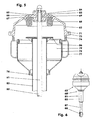
- the gas spring strut (60) includes a shock absorber (81). This is in the FIGS. 5 and 6 on the one hand the damper tube (85) with extension (87) and joint eye (88) and on the other hand, the piston rod (82) with its upper articulated support bearing (83). After the FIGS. 1 and 2 the hinge eye (88) is mounted on the trailing arm (51) near the lower wheel joint.
- the support bearing (83) rests in the form of a stiff head plate of the gas spring (62) designed as a support pot (63).
- the one-piece support pot (63) has a pot shape, which seems composed of a truncated cone shell and a cylinder jacket. It is designed, for example, as a cast iron part (GJS 400), as an aluminum cast part, as a forged part or as a deep-drawn sheet metal part. In the cylinder barrel area, it has an externally encircling stiffening rib (71) in which, for example, four threaded bores (72) are arranged, cf. FIG. 4 , In the area of the holes (72) to the rib (71) is widened. In one in the mounting frame (10) built gas spring strut (60), the rib (71) from below form positive and non-positive on the mounting brackets (43, 47) of the wishbone support (41, 45).
- the support pot (63) has to receive the support bearing (83) has a central bore (69) and eg two annular webs (65, 66), one (66) inside and one (65) outside. At the annular webs (65, 66) of the elastomeric body (84) of the support bearing (83) is securely positioned. The elastomeric body (84) is screwed clamped on the piston rod end between two discs, which are held by a sleeve at a distance.
- annular rubber buffer (68) arranged as a mechanical Federhubbegrenzung. He is held by another - the support pot (63) inside stiffening - annular web (67).
- the stop plate (86) arranged at the upper end of the damper tube (85) comes into contact with a completely spring-loaded wheel (1).
- a spring plate (76) is welded to the damper tube (85).
- the latter carries a rolling piston (75) with eg cylindrical Belgabroll Scheme.
- a hose roll (77) is arranged between the rolling piston (75) and on the support pot (63).
- the latter is held on the rolling piston (75) and on the support pot (63) in each case by means of a clamping ring.
- corresponding circumferential beads are available.
- the bead (74) of the support pot (63) lies directly below the stiffening rib (71).
- the piston rod (82) of the shock absorber (81) serves as a straight guide for the gas suspension (62).
- the support pot (63) fulfills four independent functions.
- the first function is a stiffening of the bearing of the upper arm (52).
- the support pot (63) forms together with the transverse link supports (41, 45), the longitudinal member (11) and the support element (35) a particularly dimensionally rigid assembly whose torsional rigidity is additionally increased by the screw with the lead frame (5). Further, the support pot (63) receives the support bearing (83) of the shock absorber (81), so that its separate articulation on the vehicle body (5) is eliminated.
- the wishbone (52) is used with its elastomeric joints (54, 55) on the wishbone supports (41, 45) and then the distance between the wishbone supports (41, 45) - one wheel side - is varied so that the wishbone (52 ) is movable without jamming with minimal play.
- the support pot (63) is bolted to the wishbone supports.
- the bulge of the support pot (63) of the displacer (79) is significantly increased, which is used to adjust the gas spring rate.
- FIG. 7 shows a Gasfederdämpferbein (60), which is bolted directly to the longitudinal spar (6) of the lead frame (5).
- a support flange (64) is integrally formed or attached to the support pot (63).
- the support flange is located directly on the longitudinal spar (6).
- the receptacles for the vehicle body-side joints (54, 55) of the upper transverse link (52) are additionally arranged. This solution is conceivable if the independent suspension is arranged without mounting frame on the vehicle body.
- the disassembly of the driver side strut (60) is described.
- the driver-side longitudinal spar (6) is jacked up so far that the driver-side wheel (1) can be disassembled.
- the gas spring strut (60) is disconnected from the compressed air supply and vented.
- the oblique link side joint of the Gasfederdämpferbeins (60) on the semi-trailing arm (51) is released.
- the four in the mounting brackets (43, 47) of the wishbone support (41, 45) sitting screws are loosened from above and removed.
- the joint eye (88) in the direction of travel (9) is lifted forward over the outer tie rod (98) and then taken out forward and down.
- the new gas spring strut is mounted in reverse order.
Landscapes
- Engineering & Computer Science (AREA)
- Mechanical Engineering (AREA)
- Vehicle Body Suspensions (AREA)
- Body Structure For Vehicles (AREA)
- Fluid-Damping Devices (AREA)
Applications Claiming Priority (2)
| Application Number | Priority Date | Filing Date | Title |
|---|---|---|---|
| DE102006009301A DE102006009301A1 (de) | 2006-03-01 | 2006-03-01 | Einzelradaufhängung mit fahrwerksversteifenden Gas- oder Hydraulikfederungsteilen |
| PCT/EP2007/001612 WO2007101569A1 (de) | 2006-03-01 | 2007-02-24 | Einzelradaufhängung mit fahrwerksversteifenden gas- oder hydraulikfederungsteilen |
Publications (2)
| Publication Number | Publication Date |
|---|---|
| EP1989068A1 EP1989068A1 (de) | 2008-11-12 |
| EP1989068B1 true EP1989068B1 (de) | 2010-04-21 |
Family
ID=38171234
Family Applications (1)
| Application Number | Title | Priority Date | Filing Date |
|---|---|---|---|
| EP07722924A Not-in-force EP1989068B1 (de) | 2006-03-01 | 2007-02-24 | Einzelradaufhängung mit fahrwerksversteifenden gas- oder hydraulikfederungsteilen |
Country Status (5)
| Country | Link |
|---|---|
| US (1) | US7758057B2 (enExample) |
| EP (1) | EP1989068B1 (enExample) |
| JP (1) | JP4758482B2 (enExample) |
| DE (2) | DE102006009301A1 (enExample) |
| WO (1) | WO2007101569A1 (enExample) |
Families Citing this family (7)
| Publication number | Priority date | Publication date | Assignee | Title |
|---|---|---|---|---|
| DE102012014187A1 (de) | 2012-07-18 | 2013-01-24 | Daimler Ag | Fahrzeugaufbau und Montageverfahren |
| CN102815179B (zh) * | 2012-09-04 | 2016-01-20 | 航天重型工程装备有限公司 | 一种带有油气弹簧的单纵臂式独立悬架 |
| DE102014108701A1 (de) * | 2014-06-20 | 2015-12-24 | Radkersburger Metallwarenfabrik Gmbh | Abrollkolben für eine Luftfeder |
| DE102014226225B4 (de) * | 2014-12-17 | 2020-08-27 | Zf Friedrichshafen Ag | Radaufhängungsanordnung |
| DE102015100281A1 (de) * | 2015-01-09 | 2016-07-14 | Trelleborgvibracoustic Gmbh | Verbundbauteil sowie Luftfederkomponente mit einem derartigen Verbundbauteil |
| CN109435612A (zh) * | 2018-11-15 | 2019-03-08 | 郑州智驱科技有限公司 | 轮边电机驱动客车独立悬架 |
| CN111038203B (zh) * | 2020-03-17 | 2022-11-22 | 绩溪县徽洋车桥有限责任公司 | 一种电动汽车车桥 |
Family Cites Families (15)
| Publication number | Priority date | Publication date | Assignee | Title |
|---|---|---|---|---|
| NL244801A (enExample) * | 1958-11-08 | |||
| US4332397A (en) * | 1980-07-07 | 1982-06-01 | General Motors Corporation | Steerable suspension strut with pneumatic spring |
| DE3665281D1 (en) * | 1985-07-26 | 1989-10-05 | Audi Ag | Arrangement for compensating transversal forces acting on a suspension strut and created by wheel movement |
| JP2600978B2 (ja) * | 1990-05-25 | 1997-04-16 | 日産自動車株式会社 | サスペンションのアッパリンク支持部構造 |
| JP2793429B2 (ja) * | 1992-03-11 | 1998-09-03 | 日野自動車工業株式会社 | 独立懸架式サスペンション及びリジッド式サスペンション |
| JP3488989B2 (ja) * | 1995-09-22 | 2004-01-19 | 日産自動車株式会社 | フロントサスペンション装置 |
| JP3550908B2 (ja) * | 1996-10-04 | 2004-08-04 | 日産自動車株式会社 | フロントサスペンション装置 |
| JPH10250332A (ja) * | 1997-03-14 | 1998-09-22 | Nissan Motor Co Ltd | サスペンション構造 |
| JPH11129717A (ja) * | 1997-10-31 | 1999-05-18 | Nissan Motor Co Ltd | フロントサスペンション装置 |
| EP0960046A1 (en) * | 1997-12-12 | 1999-12-01 | Holland Neway International, Inc. | Independent front suspension |
| US6398202B1 (en) * | 1999-03-06 | 2002-06-04 | Dr. Ing. H.C.F. Porsche Ag | Bearing for a shock absorber strut or a pneumatic spring |
| GB0029298D0 (en) * | 2000-12-01 | 2001-01-17 | Gibbs Int Tech Ltd | Suspension arrangement |
| US6866295B2 (en) * | 2000-12-28 | 2005-03-15 | Dana Corporation | Modular cast independent front suspension subframe |
| GB2387155B (en) * | 2002-04-05 | 2004-09-29 | Lotus Car | A road vehicle suspension unit and a method of constructing a road vehicle suspension unit and fitting the road vehicle suspension unit to a road vehicle |
| DE102004003395A1 (de) * | 2004-01-23 | 2005-08-11 | Man Nutzfahrzeuge Aktiengesellschaft | Vorderachse mit Einzelradaufhängung und lenkbaren Rädern eines Nutzfahrzeugs |
-
2006
- 2006-03-01 DE DE102006009301A patent/DE102006009301A1/de not_active Withdrawn
-
2007
- 2007-02-24 JP JP2008556694A patent/JP4758482B2/ja not_active Expired - Fee Related
- 2007-02-24 US US12/281,292 patent/US7758057B2/en not_active Expired - Fee Related
- 2007-02-24 WO PCT/EP2007/001612 patent/WO2007101569A1/de not_active Ceased
- 2007-02-24 EP EP07722924A patent/EP1989068B1/de not_active Not-in-force
- 2007-02-24 DE DE502007003508T patent/DE502007003508D1/de active Active
Also Published As
| Publication number | Publication date |
|---|---|
| JP4758482B2 (ja) | 2011-08-31 |
| US20090194966A1 (en) | 2009-08-06 |
| DE102006009301A1 (de) | 2007-09-06 |
| WO2007101569A1 (de) | 2007-09-13 |
| DE502007003508D1 (de) | 2010-06-02 |
| EP1989068A1 (de) | 2008-11-12 |
| JP2009528209A (ja) | 2009-08-06 |
| US7758057B2 (en) | 2010-07-20 |
Similar Documents
| Publication | Publication Date | Title |
|---|---|---|
| EP1989067B1 (de) | Einzelradaufhängung für eine hochlenkerachse | |
| EP1989068B1 (de) | Einzelradaufhängung mit fahrwerksversteifenden gas- oder hydraulikfederungsteilen | |
| US4193612A (en) | Elastomeric suspension system for wheeled vehicles | |
| DE102011078262B4 (de) | Einzelradaufhängung mit selbsttätiger Sturzanpassung | |
| DE102013210338A1 (de) | Mehrlenkerhinterachse für ein Fahrzeug | |
| DE102008049761A1 (de) | Einzelradaufhängung für Fahrzeugrad und damit ausgerüstete Radachse | |
| DE10304567A1 (de) | Radaufhängung für Kraftfahrzeuge | |
| EP4065392B1 (de) | Angetriebene vierlenker-hinterachse für ein kraftfahrzeug | |
| EP1557339B1 (de) | Vorderachse mit Einzelradaufhängung und lenkbaren Rädern eines Nutzfahrzeugs | |
| EP1955875B1 (de) | Radaufhängung für Kraftfahrzeuge | |
| DE19756066C2 (de) | Fahrzeugachse mit mindestens einem, mindestens einen Hebel aufweisenden, radtragenden Lenker pro Fahrzeugrad | |
| US20050263972A1 (en) | Vehicle suspension arrangement and vehicle provided with such a suspension | |
| DE102017211277B4 (de) | Radaufhängung für ein Kraftfahrzeug | |
| DE10011417B4 (de) | Einzelradaufhängung mit radführenden Schräglenkern | |
| CN102729755B (zh) | 车辆的车轮悬架 | |
| EP0642938B1 (de) | Fahrzeug-Radaufhängung | |
| DE19816803C1 (de) | Einzelradaufhängung mit einem radführenden, über eine Ausgleichswippe angelenkten Feder-Dämpferbein | |
| DE102014200420B4 (de) | Einzelradaufhängung sowie Hinterachsmodul mit Einzelradaufhängungen für ein Fahrzeug und entsprechend ausgestattetes Fahrzeug | |
| DE4339820A1 (de) | Aufhängung eines lenkbaren Vorderrades eines Kraftfahrzeugs | |
| AU648136B2 (en) | A steering axle for track-guidable commercial vehicles, particularly buses | |
| DE19949451A1 (de) | Kurbelschleifenachse mit zweiteiligen Quer- oder Schräglenkern | |
| DE102015202109A1 (de) | Einzelradaufhängung mit Luftfederelement für eine Fahrzeughinterachse sowie entsprechend ausgestattete Fahrzeughinterachse | |
| EP1348580B1 (en) | Independent suspension for a wheel of a commercial vehicle | |
| DE10250343B4 (de) | Hinterradaufhängung für ein Kraftfahrzeug | |
| DE19802488C2 (de) | Gasdruckfederung für ein radführendes Federbein |
Legal Events
| Date | Code | Title | Description |
|---|---|---|---|
| PUAI | Public reference made under article 153(3) epc to a published international application that has entered the european phase |
Free format text: ORIGINAL CODE: 0009012 |
|
| 17P | Request for examination filed |
Effective date: 20080829 |
|
| AK | Designated contracting states |
Kind code of ref document: A1 Designated state(s): DE FR SE |
|
| DAX | Request for extension of the european patent (deleted) | ||
| RBV | Designated contracting states (corrected) |
Designated state(s): DE FR SE |
|
| GRAP | Despatch of communication of intention to grant a patent |
Free format text: ORIGINAL CODE: EPIDOSNIGR1 |
|
| GRAS | Grant fee paid |
Free format text: ORIGINAL CODE: EPIDOSNIGR3 |
|
| GRAA | (expected) grant |
Free format text: ORIGINAL CODE: 0009210 |
|
| AK | Designated contracting states |
Kind code of ref document: B1 Designated state(s): DE FR SE |
|
| REF | Corresponds to: |
Ref document number: 502007003508 Country of ref document: DE Date of ref document: 20100602 Kind code of ref document: P |
|
| PG25 | Lapsed in a contracting state [announced via postgrant information from national office to epo] |
Ref country code: SE Free format text: LAPSE BECAUSE OF FAILURE TO SUBMIT A TRANSLATION OF THE DESCRIPTION OR TO PAY THE FEE WITHIN THE PRESCRIBED TIME-LIMIT Effective date: 20100421 |
|
| PLBE | No opposition filed within time limit |
Free format text: ORIGINAL CODE: 0009261 |
|
| STAA | Information on the status of an ep patent application or granted ep patent |
Free format text: STATUS: NO OPPOSITION FILED WITHIN TIME LIMIT |
|
| 26N | No opposition filed |
Effective date: 20110124 |
|
| REG | Reference to a national code |
Ref country code: FR Ref legal event code: ST Effective date: 20111102 |
|
| PG25 | Lapsed in a contracting state [announced via postgrant information from national office to epo] |
Ref country code: FR Free format text: LAPSE BECAUSE OF NON-PAYMENT OF DUE FEES Effective date: 20110228 |
|
| PGFP | Annual fee paid to national office [announced via postgrant information from national office to epo] |
Ref country code: DE Payment date: 20170428 Year of fee payment: 11 |
|
| REG | Reference to a national code |
Ref country code: DE Ref legal event code: R119 Ref document number: 502007003508 Country of ref document: DE |
|
| PG25 | Lapsed in a contracting state [announced via postgrant information from national office to epo] |
Ref country code: DE Free format text: LAPSE BECAUSE OF NON-PAYMENT OF DUE FEES Effective date: 20180901 |