EP1988752A1 - Led illumination device - Google Patents
Led illumination device Download PDFInfo
- Publication number
- EP1988752A1 EP1988752A1 EP07737313A EP07737313A EP1988752A1 EP 1988752 A1 EP1988752 A1 EP 1988752A1 EP 07737313 A EP07737313 A EP 07737313A EP 07737313 A EP07737313 A EP 07737313A EP 1988752 A1 EP1988752 A1 EP 1988752A1
- Authority
- EP
- European Patent Office
- Prior art keywords
- light
- emitting module
- sensor
- led luminaire
- light emitting
- Prior art date
- Legal status (The legal status is an assumption and is not a legal conclusion. Google has not performed a legal analysis and makes no representation as to the accuracy of the status listed.)
- Granted
Links
Images


Classifications
-
- F—MECHANICAL ENGINEERING; LIGHTING; HEATING; WEAPONS; BLASTING
- F21—LIGHTING
- F21V—FUNCTIONAL FEATURES OR DETAILS OF LIGHTING DEVICES OR SYSTEMS THEREOF; STRUCTURAL COMBINATIONS OF LIGHTING DEVICES WITH OTHER ARTICLES, NOT OTHERWISE PROVIDED FOR
- F21V5/00—Refractors for light sources
- F21V5/04—Refractors for light sources of lens shape
-
- F—MECHANICAL ENGINEERING; LIGHTING; HEATING; WEAPONS; BLASTING
- F21—LIGHTING
- F21V—FUNCTIONAL FEATURES OR DETAILS OF LIGHTING DEVICES OR SYSTEMS THEREOF; STRUCTURAL COMBINATIONS OF LIGHTING DEVICES WITH OTHER ARTICLES, NOT OTHERWISE PROVIDED FOR
- F21V23/00—Arrangement of electric circuit elements in or on lighting devices
- F21V23/04—Arrangement of electric circuit elements in or on lighting devices the elements being switches
- F21V23/0442—Arrangement of electric circuit elements in or on lighting devices the elements being switches activated by means of a sensor, e.g. motion or photodetectors
- F21V23/0457—Arrangement of electric circuit elements in or on lighting devices the elements being switches activated by means of a sensor, e.g. motion or photodetectors the sensor sensing the operating status of the lighting device, e.g. to detect failure of a light source or to provide feedback to the device
-
- F—MECHANICAL ENGINEERING; LIGHTING; HEATING; WEAPONS; BLASTING
- F21—LIGHTING
- F21V—FUNCTIONAL FEATURES OR DETAILS OF LIGHTING DEVICES OR SYSTEMS THEREOF; STRUCTURAL COMBINATIONS OF LIGHTING DEVICES WITH OTHER ARTICLES, NOT OTHERWISE PROVIDED FOR
- F21V5/00—Refractors for light sources
- F21V5/007—Array of lenses or refractors for a cluster of light sources, e.g. for arrangement of multiple light sources in one plane
-
- H—ELECTRICITY
- H05—ELECTRIC TECHNIQUES NOT OTHERWISE PROVIDED FOR
- H05B—ELECTRIC HEATING; ELECTRIC LIGHT SOURCES NOT OTHERWISE PROVIDED FOR; CIRCUIT ARRANGEMENTS FOR ELECTRIC LIGHT SOURCES, IN GENERAL
- H05B45/00—Circuit arrangements for operating light-emitting diodes [LED]
- H05B45/20—Controlling the colour of the light
- H05B45/22—Controlling the colour of the light using optical feedback
-
- H—ELECTRICITY
- H05—ELECTRIC TECHNIQUES NOT OTHERWISE PROVIDED FOR
- H05B—ELECTRIC HEATING; ELECTRIC LIGHT SOURCES NOT OTHERWISE PROVIDED FOR; CIRCUIT ARRANGEMENTS FOR ELECTRIC LIGHT SOURCES, IN GENERAL
- H05B45/00—Circuit arrangements for operating light-emitting diodes [LED]
- H05B45/40—Details of LED load circuits
- H05B45/44—Details of LED load circuits with an active control inside an LED matrix
- H05B45/46—Details of LED load circuits with an active control inside an LED matrix having LEDs disposed in parallel lines
-
- F—MECHANICAL ENGINEERING; LIGHTING; HEATING; WEAPONS; BLASTING
- F21—LIGHTING
- F21Y—INDEXING SCHEME ASSOCIATED WITH SUBCLASSES F21K, F21L, F21S and F21V, RELATING TO THE FORM OR THE KIND OF THE LIGHT SOURCES OR OF THE COLOUR OF THE LIGHT EMITTED
- F21Y2115/00—Light-generating elements of semiconductor light sources
- F21Y2115/10—Light-emitting diodes [LED]
-
- Y—GENERAL TAGGING OF NEW TECHNOLOGICAL DEVELOPMENTS; GENERAL TAGGING OF CROSS-SECTIONAL TECHNOLOGIES SPANNING OVER SEVERAL SECTIONS OF THE IPC; TECHNICAL SUBJECTS COVERED BY FORMER USPC CROSS-REFERENCE ART COLLECTIONS [XRACs] AND DIGESTS
- Y10—TECHNICAL SUBJECTS COVERED BY FORMER USPC
- Y10S—TECHNICAL SUBJECTS COVERED BY FORMER USPC CROSS-REFERENCE ART COLLECTIONS [XRACs] AND DIGESTS
- Y10S362/00—Illumination
- Y10S362/80—Light emitting diode
-
- Y—GENERAL TAGGING OF NEW TECHNOLOGICAL DEVELOPMENTS; GENERAL TAGGING OF CROSS-SECTIONAL TECHNOLOGIES SPANNING OVER SEVERAL SECTIONS OF THE IPC; TECHNICAL SUBJECTS COVERED BY FORMER USPC CROSS-REFERENCE ART COLLECTIONS [XRACs] AND DIGESTS
- Y10—TECHNICAL SUBJECTS COVERED BY FORMER USPC
- Y10S—TECHNICAL SUBJECTS COVERED BY FORMER USPC CROSS-REFERENCE ART COLLECTIONS [XRACs] AND DIGESTS
- Y10S362/00—Illumination
- Y10S362/803—Photo safe lamp
Definitions
- the present invention relates to a light emitting diode luminaire composed of LEDs of different colors to emit a light of desired chromaticity.
- the LED luminaire includes a circuit board mounting thereon plural kinds of LEDs of different colors (e.g., a red LED, a green LED, and a blue LED), a main body carrying the circuit board, and an optical member covering surfaces of the LEDs.
- the LED luminaire further includes a single photodiode for detecting light outputs from all of the LEDs and a controller for performing a feedback control of regulating an amount of forward electric current to each LED in order to keep the light from the individual LED at a predetermined desired level.
- the LED luminaire since the emitted light from each of LEDs is transmitted to the photodiode through an optical fiber, the LED luminaire has one disadvantage that it is difficult to detect light stably from all of the LEDs. Furthermore, since the control unit drives the red, green, and blue LEDs individually at short intervals and determines a light output level for each color, the LED luminaire has another disadvantage that it is difficult to adjust the chromaticity based upon the light of the mixed-color obtained from these LEDs. i.e., the light practically emitted from the LED luminaire.
- the present invention has been developed in view of the above problems and aims to propose an LED luminaire which is capable of accurately adjusting a mixed-color light to develop the light of a desired chromaticity.
- the LED luminaire according to the present invention includes a light emitting module having plural kinds of LEDs of emitting lights of different colors to provide the mixed-color light, a mixture of the lights from the individual LEDs, a lens unit having a lens for diffusing the mixed-color light from the light emitting module, a light output controller for controlling an electric current fed to each of the LEDs in the light emitting module, and a light sensor for sensing the mixed-color light from the light emitting module.
- the light output controller is configured to perform feedback control on the electric current fed to each of the LEDs such that the mixed-color light from the light emitting module may be adjusted at a desired chromaticity, based upon the light output levels for specific colors detected by the light sensor.
- the lens unit includes a light guide for guiding the mixed-color light from the lens to the light sensor. With the provision of the light guide, the mixed-color light, i.e., the mixture of the lights from all of the LEDs can be transmitted to the light sensor efficiently, enabling to accurately adjust the chromaticity of the mixed-color light.
- the LED luminaire in accordance with the present invention further includes a memory unit for storing reference values of the light levels for the specific colors that defines the predetermined chromaticity, such as red, green, and blue.
- the light output controller controls the electric current fed to each the LEDs based upon the reference values stored in the memory unit. Consequently, the luminaire can be realized to generate the lights of different values of chromaticity by selection of the reference values for the light level for each color in the memory unit.
- the light sensor preferably includes a plurality of color filters each selectively passing the light of each specific color, and a plurality of level sensors each detecting the light level of the specific color passed through each of the color filters.
- a plurality of color filters each selectively passing the light of each specific color
- a plurality of level sensors each detecting the light level of the specific color passed through each of the color filters.
- the light sensor may be composed of a spectroscopic element for spectrally diffracting the mixed-color light from at least one light-emitting module into the lights of the specific colors, and a level sensor for detecting the light level for each of the specific colors obtained by means of the spectroscopy.
- a light collecting part is formed integrally with the light lens unit in a vicinity of the light sensor.
- the light guide has a cross-sectional area which decreases towards the light collecting part than at a portion close to the light sensor so as to effectively transmit the mixed-color light to the light sensor.
- the present invention is preferred to include a plurality of the light emitting modules which are located at different positions with their respective lens spaced from the light sensor by the individual light guides of different optical path lengths.
- the light guide is configured to have a greater cross-sectional area than the light guide of shorter light path length.
- the light sensor may be mounted together with the light emitting module on a circuit board supported by a main body. In this case, the distance of the light guide from the lens unit to the light sensor can be shortened to realize the lens unit with a simple configuration.
- the light sensor may be disposed on a back surface of the main body.
- the light guide extends from a front surface of the main body to the back surface through the circuit board mounting the light emitting module, and is coupled to the light sensor.
- the light sensor may be incorporated into a control unit provided separately from the main body.
- the light guide extends to the back surface of the main body through the circuit board, and is coupled to the light sensor by means of an optical fiber.
- the lens unit is preferably provided with a reflector.
- the reflector reflects the external light entering from a front side of the lens unit, such that the light from the light emitting module is directed from the light guide into a path leading to the light sensor for reducing disturbances caused by an ambient light. Consequently, the light sensor can detect the mixed-color light only from the light emitting module for accurate adjustment of chromaticity.
- the reflector may be formed on one side of faces of a hollow cavity formed in the lens unit. With the reflector thus formed in the lens unit, the mixed-color light guided from the lens can be reflected toward the light sensor, so as to be efficiently collected at the light sensor.
- the LED luminaire according to the present invention can be configured to emit the light of chromaticity in match with that of an ambient light.
- an ambient light sensor for detecting the ambient light is provided to detect light levels for the specific colors corresponding to the colors of the lights emitted from the plural kinds of the LEDs.
- the detected light levels are output to the light output controller which controls the electric current fed to each of the LEDs in at least one light emitting module such that a ratio of the light levels of the mixed-color light becomes equal to that of the light levels output from the ambient light sensor.
- the LED luminaire can emit the light that has almost the same chromaticity as that of another coexisting luminaires. Consequently, it is possible to emit the light of a uniform chromaticity over a wide range with the use of the plural LED luminaires.
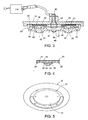
- FIG. 1 is a bottom view of an LED luminaire in accordance with a first embodiment of the present invention
- the LED luminaire in accordance with a first embodiment of the present invention will be described with reference to FIGS. 1 to 10 .
- the LED luminaire in accordance with this embodiment is configured as a ceiling light.
- the LED luminaire includes a disc-shaped main body 10 attached to a ceiling 100, a plurality of light emitting modules 20 arranged on a front surface of the main body 10 , and a lens unit 40 covering a plurality of the light emitting modules 20 on the front surface of the main body 10 .
- a circular recess 12 is formed on the front surface of the main body 10 to accommodate a plurality of the light emitting modules 20 and the lens unit 40 .
- a decorative ring 50 is attached to a periphery of the recess 12 of the main body 10 to surround the lens unit 40 , while concealing screws 15 used for securing the main body 10 to the ceiling 100 .
- the decorative ring 50 is removably attached to the main body 10 with hooks 52 projecting from a back surface of the decorative ring 50 to engage with holes 14 .
- each light emitting module 20 is configured to emit a white light by combination of the plural LEDs emitting the lights of different colors, i.e., a red LED 22 , a green LED 23 , and a blue LED which are arranged on the surface of a substrate 21 .
- the LEDs are prepared as bare chips, and these bare chips are electrically connected to circuit patterns formed on the substrate 21 by wire bonding.
- the LEDs and the wires are encapsulated with transparent sealing resins (e.g., silicone resins or an epoxy resins), to form a light emitting part 25 enclosing the LEDs. It is noted that the LEDs may be mounted on the substrate 21 by a flip-chip technique.
- Electrodes 26 electrically connected to the LEDs through the circuit pattern are formed on a periphery of the surface of the substrate 21 . Also, an organic green sheet 28 made of a dielectric material with a high thermal conductivity is formed on the back surface of the substrate 21 . Since the organic green sheet 28 is secured to the main body 10 made of metals with a higher thermal conductivity such as aluminum or copper, the heat generated in the LEDs is diffused to the main body 10 .
- the plural light emitting modules 20 are mounted on a single circuit board 30 which is accommodated in the circular recess 12 formed in the front surface of the main body 10 , and are arranged around a center of the main body 10 .
- a plurality of circular openings 34 are formed such that the light emitting part 25 of each light emitting module 20 is exposed at each of the openings 34 .
- the electrodes 26 on the periphery of the surface of the substrate 21 in each light emitting module 20 are electrically connected to the circuit patterns formed on a back surface of the circuit board 30 .
- the organic green sheet 28 is formed of a thermoplastic resin sheet material with the high thermal conductivity and a high fluidity when heated.
- the material may be an epoxy resin layer highly filled with a filler (e.g. a silica or an alumina), or the like.
- the organic green sheet 28 is secured to the main body 10 by its plastic deformation when heated.
- An electronic circuit of a light output controller 60 is composed of the circuit board 30 mounting thereon electronic components, and modifies a chromaticity of the light emitted from the light emitting module 20 by controlling the electric current fed to each of LED 22 , 23 , and 24 in each light emitting module 20 .
- a power source unit 110 is disposed on a back surface of the main body 10 to supply an electric power to the light output controller 60 through wires 32 .
- the lens unit 40 is molded from a transparent material to include a plurality of lenses 42 respectively corresponding to the light emitting modules 20 , and fastened to a front surface of the main body 10 with screws 11 in order to conceal a front surface of the circuit board 30 .
- the screws 11 are inserted from the back surface of the main body 10 into bosses 41 formed in a peripheral portion of the lens unit 40 .
- a side wall 43 is formed in the periphery of the lens unit 40 such that the lens unit is fitted within the periphery of the circular recess 12 of the main body 10 .
- Each lens 42 is designed as a Fresnel lens to distribute the light emitted from the light emitting module 20 .
- Each lens 42 has a bulge 44 projecting towards the circuit board 30 .
- An upper periphery of the bulge 44 contacts with a periphery of the circular opening 34 of the circuit board 30 to align each lens with each light emitting module 20 .
- the light emitting part 25 of the light emitting module 20 is accommodated in a concavity 45 formed in a top end of the bulge 44 .
- the outer shape of the bulge 44 is designed such that the light entering from a side wall of the concavity 45 is reflected inwardly and led to an emitting surface of the lens 42 .
- the lens unit 40 includes a light guide 47 for guiding the light emitted from each light emitting module 20 partially into a light collecting part 46 formed at a center of the lens unit 40 .
- the light collecting part 46 is shaped into a convex lens to emit the collected light toward the light sensor 80 disposed on circuit board 30 .
- a film of reflector 48 is formed on the outer surface of the light collecting part 46 in order to prevent ambient light from entering into the light sensor 80 .
- the whole lens unit 40 is molded from a transparent material, e.g., acrylic resin, polycarbonate resin, and glass, or a combination of transparent material and metallic material. In the latter case, when the light guide 47 and light collecting part 46 are made of transparent materials and the remaining parts are made of metal materials, it is possible to promote the dissipation of heat caused by light emitting of the LEDs.
- the light sensor 80 includes three kinds of color filters (not illustrated) passing selectively each of the lights emitted from the red LED 22 , the green LED 23 , and the blue LED 24 , and a light level sensor (not illustrated) composed of a plurality of photodiodes having a photo-sensitivity over a whole frequency range of visual light.
- the light sensor 80 detects light levels of red, green, and blue simultaneously, and then outputs the light levels to the light output controller 60 . It is noted that only one level sensor may be used to detect the light level of each color at predetermined time intervals by time-division processing.
- the light output controller 60 is provided with a memory unit 65 and a color signal generating unit 66 .
- the memory unit 65 holds a reference value of light level for each of red, green, and blue, and the color signal generating unit 66 determines a current command for each color such that the LED 22 , 23 , and 24 emit the lights of which the intensities are based upon the reference values.
- a driving circuit R 62 , a driving circuit G 63 , and a driving circuit B 64 operate to feed the electric currents to the LEDs 22, 23, and 24 respectively, causing the light emission from the LEDs in each of the light emitting modules 20.
- the memory unit 65 is arranged to determine reference values so as to realize a white-color light from the light emitting modules 20 by mixing the luminescent colors of the LEDs.
- the light level for each color of the light detected by the light sensor 80 is sent to the color signal generating unit 66 to perform the feedback control for determining the individual current commands such that such that the light level coincides with the reference value stored in the memory unit 65 , in order to maintain a constant chromaticity of the light emitted from each light emitting module 20 .
- the light guides 47 extending from each light emitting module 20 to the light sensor 80 have optical path lengths different from each other. Due to the differing optical lengths of the individual light paths, there would be inherent variations in an amount of the light leading to the light sensor 80 . In order to avoid the variations, the light guide 47 of a longer optical path is designed to have a larger cross-section than that of a shorter optical path, thereby assuring higher accuracy of detecting a chromaticity of the light emitted from the whole LED luminaire.
- the LED luminaire in accordance with the embodiment in addition to the light sensor 80 for sensing the light emitted from each light emitting module 20 , may be provided with an ambient light sensor 90 for sensing ambient light to perform an additional matching function in which the light emitting module 20 can emit the light in match with a chromaticity of the light emitted from an ambient light source.
- the ambient light sensor 90 is disposed on the periphery of the front surface of the main body 10 in order to detect light levels for red, green, and blue color independently.
- the color signal generating unit 66 is arranged to receive light levels for the three colors of the light detected by the ambient light sensor 90 , instead of utilizing the reference current command stored in the memory unit 65.
- FIG. 10 shows one example of an illumination system using the above matching function.
- the illumination system is configured to arrange a plurality of LED luminaires "L" around a reference luminaire "X" in order to conform the chromaticity of the light emitted from the reference luminaire to those of the lights from the LED luminaires located around it.
- the feedback control is made to regulate the electric current to each LED based upon an average value of light levels of each color detected by the two ambient light sensors 90 .
- the two ambient light sensors 90 are positioned on the periphery of the main body 10 opposite to each other in its diametrical direction.
- the number of the ambient light sensors 90 is not limited to two, but may be one or more than two.
- the LED luminaire may include a switch for selectively deactivating one or more ambient light sensors 90 for selecting only the necessary ambient light, while eliminating the influence of undesired ambient light.
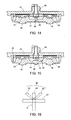
- FIG. 11 shows a first modification in the above embodiment.
- the embodiment is configured to decrease gradually the cross-sectional area, which means the thickness, of the light guide 47 extending from the lens 42 to the light collecting part 46 in a direction toward the light collecting part 46 , in order to improve light transmitting efficiency of the light entering into the light collecting part 46 .
- FIG. 12 shows a second modification in the above embodiment, in which the projecting portion of the light collecting part 46 is formed on the back surface of the lens unit 40 facing to the light sensor 80 .
- FIG. 13 shows a third modification in the above embodiment.
- the modification is configured to have the light collecting part 46 of which back surface projects towards the light sensor 80 from the reflector 48 embedded in the center of the front surface of the lens unit 40 corresponding to the light sensor 80 .
- FIG. 14 shows a fourth modification in the above embodiment.
- the modification is configured such that the reflector 48 of a triangular cross section is embedded in the center of the front surface of the lens unit 40 in order to prevent an external light from entering into the light sensor 80 and simultaneously reflect the light passing through the light guide 47 toward the light sensor 80 .
- This configuration enhances incident efficiency of the light entering into the light sensor 80 .
- FIGS. 15 and 16 show a fifth modification in the above embodiment.
- the light sensor 80 is composed of a spectroscopic element 81 by which the light "H" transmitted through the light guide 47 is spectrally diffracted into each color of red, green, and blue, and a plurality of photodiodes 82 , 83 , and 84 functioning as a level sensor for detecting the light level of each color diffracted spectrally.
- the spectroscopic element 81 is formed as a diffraction grating on the back surface of the light collecting part 46 in the lens unit 40 , it may be separately formed from the lens unit 40 .
- FIG. 17 shows an LED luminaire in accordance with a second embodiment of the present invention.
- the LED luminaire includes the light sensor 80 which is arranged at the back surface of the main body 10 to electrically to electrically connect through a wire 88 with the light output controller 60 accommodated in a control unit 70 disposed separately from the main body 10 .
- the light guide 47 formed in the lens unit 40 is configured to extend from the center of the back surface of the lens unit 40 to the back surface of the main body 10 through the circuit board 30 , and optically coupled to the light sensor 80 .
- the main body is formed at its back surface with a tube 16 holding a thermal insulation sleeve 18 which supports the light sensor 80 at its one end for reducing the insulation sleeve from the main body 10 .
- a front end of the light guide 47 is inserted into the thermal insulation sleeve 18, and outputs the light from the lens 42 to the light sensor 80 .
- the control unit 70 is connected to a power source unit to feed an electric power to each of the LEDs.
- Other parts are like those of the first embodiment, so that like parts are designated by like reference numerals.
- FIG. 18 shows a first modification of the second embodiment.
- the control unit 70 is provided separately from the main body 10 , and accommodates therein the light sensor 80 together with the light output controller 60, and the light guide 47 extending from the center of the back surface of the lens unit 40 is optically coupled to the light sensor 80 through an optical fiber 72 .
- the tip of the light guide 47 is inserted into the thermal insulation sleeve 18 which is embedded within the tube 16 projecting to the back surface of the main body 10.
- the tip is connected to one end of the optical fiber 72 .
- the other end of the optical fiber 72 is coupled to the light sensor 80 in the control unit 70 .
- the modification also includes a hollow cavity 45 at the center of the lens unit 40 .
- a film of the reflector 48 is provided on the wall of hollow cavity 45 , preventing the light from traveling to the light guide 47 extending from the back surface opposite to the hollow cavity 45 after being incident from the front surface of the lens unit 40 .
- each light emitting module is composed of the red LED 22 , the green LED 23 , and the blue LED 24
- the present invention is not limited to the composition.
- a desired mixed color may be obtained by combining any LEDs emitting the lights of colors other than red, green, and blue.
Abstract
Description
- The present invention relates to a light emitting diode luminaire composed of LEDs of different colors to emit a light of desired chromaticity.
- International Patent Publication No.
W00037904 - The present invention has been developed in view of the above problems and aims to propose an LED luminaire which is capable of accurately adjusting a mixed-color light to develop the light of a desired chromaticity. The LED luminaire according to the present invention includes a light emitting module having plural kinds of LEDs of emitting lights of different colors to provide the mixed-color light, a mixture of the lights from the individual LEDs, a lens unit having a lens for diffusing the mixed-color light from the light emitting module, a light output controller for controlling an electric current fed to each of the LEDs in the light emitting module, and a light sensor for sensing the mixed-color light from the light emitting module. The light output controller is configured to perform feedback control on the electric current fed to each of the LEDs such that the mixed-color light from the light emitting module may be adjusted at a desired chromaticity, based upon the light output levels for specific colors detected by the light sensor. A characterizing feature of the present invention is that the lens unit includes a light guide for guiding the mixed-color light from the lens to the light sensor. With the provision of the light guide, the mixed-color light, i.e., the mixture of the lights from all of the LEDs can be transmitted to the light sensor efficiently, enabling to accurately adjust the chromaticity of the mixed-color light.
- The LED luminaire in accordance with the present invention further includes a memory unit for storing reference values of the light levels for the specific colors that defines the predetermined chromaticity, such as red, green, and blue. The light output controller controls the electric current fed to each the LEDs based upon the reference values stored in the memory unit. Consequently, the luminaire can be realized to generate the lights of different values of chromaticity by selection of the reference values for the light level for each color in the memory unit.
- The light sensor preferably includes a plurality of color filters each selectively passing the light of each specific color, and a plurality of level sensors each detecting the light level of the specific color passed through each of the color filters. Thus, it is possible to detect the light level of the specific colors emitted simultaneously and individually from the plural kinds of LEDs in the light emitting module.
- Alternatively, the light sensor may be composed of a spectroscopic element for spectrally diffracting the mixed-color light from at least one light-emitting module into the lights of the specific colors, and a level sensor for detecting the light level for each of the specific colors obtained by means of the spectroscopy.
- It is preferred that a light collecting part is formed integrally with the light lens unit in a vicinity of the light sensor. In this case, the light guide has a cross-sectional area which decreases towards the light collecting part than at a portion close to the light sensor so as to effectively transmit the mixed-color light to the light sensor.
- The present invention is preferred to include a plurality of the light emitting modules which are located at different positions with their respective lens spaced from the light sensor by the individual light guides of different optical path lengths. The light guide is configured to have a greater cross-sectional area than the light guide of shorter light path length. With this arrangement, it is possible to feed the light at a uniform amount from a plurality of the light emitting modules to the light sensor, irrespective of differing optical length of the light guides, thereby giving the light of desired chromaticity to the entire light from the combination of the light emitting modules
- The light sensor may be mounted together with the light emitting module on a circuit board supported by a main body. In this case, the distance of the light guide from the lens unit to the light sensor can be shortened to realize the lens unit with a simple configuration.
- Alternatively, the light sensor may be disposed on a back surface of the main body. In this case, the light guide extends from a front surface of the main body to the back surface through the circuit board mounting the light emitting module, and is coupled to the light sensor.
- Moreover, the light sensor may be incorporated into a control unit provided separately from the main body. In this case, the light guide extends to the back surface of the main body through the circuit board, and is coupled to the light sensor by means of an optical fiber. With the above configuration, the mixed-color light from the light emitting module can be efficiently transmitted to the control unit provided separately from the main body, for increasing design flexibility of the LED luminaire.
- Furthermore, the lens unit is preferably provided with a reflector.
The reflector reflects the external light entering from a front side of the lens unit, such that the light from the light emitting module is directed from the light guide into a path leading to the light sensor for reducing disturbances caused by an ambient light. Consequently, the light sensor can detect the mixed-color light only from the light emitting module for accurate adjustment of chromaticity. - The reflector may be formed on one side of faces of a hollow cavity formed in the lens unit. With the reflector thus formed in the lens unit, the mixed-color light guided from the lens can be reflected toward the light sensor, so as to be efficiently collected at the light sensor.
- Furthermore, the LED luminaire according to the present invention can be configured to emit the light of chromaticity in match with that of an ambient light. In this case, an ambient light sensor for detecting the ambient light is provided to detect light levels for the specific colors corresponding to the colors of the lights emitted from the plural kinds of the LEDs. The detected light levels are output to the light output controller which controls the electric current fed to each of the LEDs in at least one light emitting module such that a ratio of the light levels of the mixed-color light becomes equal to that of the light levels output from the ambient light sensor. With this configuration, the LED luminaire can emit the light that has almost the same chromaticity as that of another coexisting luminaires. Consequently, it is possible to emit the light of a uniform chromaticity over a wide range with the use of the plural LED luminaires.
-
FIG. 1 is a bottom view of an LED luminaire in accordance with a first embodiment of the present invention; -
FIG. 2 is a partly broken away front view of the LED luminaire in the above embodiment; -
FIG. 3 is a cross sectional view of the LED luminaire in the above embodiment; -
FIG 4 is a cross sectional view of a light emitting module of the LED luminaire in the above embodiment; -
FIG. 5 is a perspective view of a main body of the LED luminaire in the above embodiment; -
FIG. 6 is a bottom view of a lens unit of the LED luminaire in the above embodiment; -
FIG. 7 is a cross sectional view of the above lens unit; -
FIG. 8 is a perspective view of a decorative ring of the LED luminaire in the above embodiment; -
FIG. 9 is a block diagram showing a circuit configuration of the LED luminaire in the above embodiment; -
FIG. 10 is a schematic view of one example of the LED luminaire in the above embodiment; -
FIG. 11 is a cross sectional view showing a first modification of the LED luminaire in the above embodiment; -
FIG. 12 is a cross sectional view showing a second modification of the LED luminaire in the above embodiment; -
FIG. 13 is a cross sectional view showing a third modification of the LED luminaire in the above embodiment; -
FIG. 14 is a cross sectional view showing a fourth modification of the LED luminaire in the above embodiment; -
FIG 15 is a cross sectional view showing a fifth modification of the LED luminaire in the above embodiment; -
FIG. 16 is a schematic view of a color filter of the LED luminaire shown inFIG. 14 ; -
FIG. 17 is a cross sectional view of an LED luminaire in accordance with a second embodiment of the present invention; and -
FIG. 18 is a cross sectional view showing a first modification of the LED luminaire in the above embodiment. - The LED luminaire in accordance with a first embodiment of the present invention will be described with reference to
FIGS. 1 to 10 . The LED luminaire in accordance with this embodiment is configured as a ceiling light. As shown inFIG 2 , the LED luminaire includes a disc-shapedmain body 10 attached to aceiling 100, a plurality oflight emitting modules 20 arranged on a front surface of themain body 10, and alens unit 40 covering a plurality of thelight emitting modules 20 on the front surface of themain body 10. As shown inFIG. 5 , acircular recess 12 is formed on the front surface of themain body 10 to accommodate a plurality of thelight emitting modules 20 and thelens unit 40. Furthermore, adecorative ring 50 is attached to a periphery of therecess 12 of themain body 10 to surround thelens unit 40, while concealingscrews 15 used for securing themain body 10 to theceiling 100. As shown inFIG. 8 , thedecorative ring 50 is removably attached to themain body 10 withhooks 52 projecting from a back surface of thedecorative ring 50 to engage withholes 14. - As shown in
FIG. 4 , each light emittingmodule 20 is configured to emit a white light by combination of the plural LEDs emitting the lights of different colors, i.e., ared LED 22, agreen LED 23, and a blue LED which are arranged on the surface of asubstrate 21. The LEDs are prepared as bare chips, and these bare chips are electrically connected to circuit patterns formed on thesubstrate 21 by wire bonding. The LEDs and the wires are encapsulated with transparent sealing resins (e.g., silicone resins or an epoxy resins), to form alight emitting part 25 enclosing the LEDs. It is noted that the LEDs may be mounted on thesubstrate 21 by a flip-chip technique.Electrodes 26 electrically connected to the LEDs through the circuit pattern are formed on a periphery of the surface of thesubstrate 21. Also, an organicgreen sheet 28 made of a dielectric material with a high thermal conductivity is formed on the back surface of thesubstrate 21. Since the organicgreen sheet 28 is secured to themain body 10 made of metals with a higher thermal conductivity such as aluminum or copper, the heat generated in the LEDs is diffused to themain body 10. - The plural
light emitting modules 20 are mounted on asingle circuit board 30 which is accommodated in thecircular recess 12 formed in the front surface of themain body 10, and are arranged around a center of themain body 10. In thecircuit board 30, a plurality ofcircular openings 34 are formed such that thelight emitting part 25 of each light emittingmodule 20 is exposed at each of theopenings 34. Theelectrodes 26 on the periphery of the surface of thesubstrate 21 in each light emittingmodule 20 are electrically connected to the circuit patterns formed on a back surface of thecircuit board 30. As a result of securing the organicgreen sheet 28, which is formed on the opposite surface of thesubstrate 21 in each light emittingmodule 20, to themain body 10, thecircuit board 30 is held in themain body 10. The organicgreen sheet 28 is formed of a thermoplastic resin sheet material with the high thermal conductivity and a high fluidity when heated. The material may be an epoxy resin layer highly filled with a filler (e.g. a silica or an alumina), or the like. The organicgreen sheet 28 is secured to themain body 10 by its plastic deformation when heated. - An electronic circuit of a
light output controller 60 is composed of thecircuit board 30 mounting thereon electronic components, and modifies a chromaticity of the light emitted from thelight emitting module 20 by controlling the electric current fed to each ofLED module 20. Apower source unit 110 is disposed on a back surface of themain body 10 to supply an electric power to thelight output controller 60 throughwires 32. - As shown in
FIGS. 6 and 7 , thelens unit 40 is molded from a transparent material to include a plurality oflenses 42 respectively corresponding to thelight emitting modules 20, and fastened to a front surface of themain body 10 withscrews 11 in order to conceal a front surface of thecircuit board 30. Thescrews 11 are inserted from the back surface of themain body 10 intobosses 41 formed in a peripheral portion of thelens unit 40. Aside wall 43 is formed in the periphery of thelens unit 40 such that the lens unit is fitted within the periphery of thecircular recess 12 of themain body 10. Eachlens 42 is designed as a Fresnel lens to distribute the light emitted from thelight emitting module 20. Eachlens 42 has abulge 44 projecting towards thecircuit board 30. An upper periphery of thebulge 44 contacts with a periphery of thecircular opening 34 of thecircuit board 30 to align each lens with each light emittingmodule 20. Thelight emitting part 25 of thelight emitting module 20 is accommodated in aconcavity 45 formed in a top end of thebulge 44. The outer shape of thebulge 44 is designed such that the light entering from a side wall of theconcavity 45 is reflected inwardly and led to an emitting surface of thelens 42. - The
lens unit 40 includes alight guide 47 for guiding the light emitted from each light emittingmodule 20 partially into alight collecting part 46 formed at a center of thelens unit 40. Thelight collecting part 46 is shaped into a convex lens to emit the collected light toward thelight sensor 80 disposed oncircuit board 30. On the outer surface of thelight collecting part 46, a film ofreflector 48 is formed in order to prevent ambient light from entering into thelight sensor 80. Thewhole lens unit 40 is molded from a transparent material, e.g., acrylic resin, polycarbonate resin, and glass, or a combination of transparent material and metallic material. In the latter case, when thelight guide 47 andlight collecting part 46 are made of transparent materials and the remaining parts are made of metal materials, it is possible to promote the dissipation of heat caused by light emitting of the LEDs. - The
light sensor 80 includes three kinds of color filters (not illustrated) passing selectively each of the lights emitted from thered LED 22, thegreen LED 23, and theblue LED 24, and a light level sensor (not illustrated) composed of a plurality of photodiodes having a photo-sensitivity over a whole frequency range of visual light. Thelight sensor 80 detects light levels of red, green, and blue simultaneously, and then outputs the light levels to thelight output controller 60. It is noted that only one level sensor may be used to detect the light level of each color at predetermined time intervals by time-division processing. - As shown in
FIG. 9 , thelight output controller 60 is provided with amemory unit 65 and a colorsignal generating unit 66. Thememory unit 65 holds a reference value of light level for each of red, green, and blue, and the colorsignal generating unit 66 determines a current command for each color such that theLED LEDs light emitting modules 20. Typically, thememory unit 65 is arranged to determine reference values so as to realize a white-color light from thelight emitting modules 20 by mixing the luminescent colors of the LEDs. - The light level for each color of the light detected by the
light sensor 80 is sent to the colorsignal generating unit 66 to perform the feedback control for determining the individual current commands such that such that the light level coincides with the reference value stored in thememory unit 65, in order to maintain a constant chromaticity of the light emitted from each light emittingmodule 20. - In the LED luminaire in accordance with the embodiment, as shown in
FIGS. 1 and6 , since a plurality of thelenses 42 are arranged at positions having different distances from thelight collecting part 46 located at the center of thelens unit 40, the light guides 47 extending from each light emittingmodule 20 to thelight sensor 80 have optical path lengths different from each other. Due to the differing optical lengths of the individual light paths, there would be inherent variations in an amount of the light leading to thelight sensor 80. In order to avoid the variations, thelight guide 47 of a longer optical path is designed to have a larger cross-section than that of a shorter optical path, thereby assuring higher accuracy of detecting a chromaticity of the light emitted from the whole LED luminaire. - The LED luminaire in accordance with the embodiment, in addition to the
light sensor 80 for sensing the light emitted from each light emittingmodule 20, may be provided with an ambientlight sensor 90 for sensing ambient light to perform an additional matching function in which thelight emitting module 20 can emit the light in match with a chromaticity of the light emitted from an ambient light source. Like theabove light sensor 80, the ambientlight sensor 90 is disposed on the periphery of the front surface of themain body 10 in order to detect light levels for red, green, and blue color independently. For performing the matching function, the colorsignal generating unit 66 is arranged to receive light levels for the three colors of the light detected by the ambientlight sensor 90, instead of utilizing the reference current command stored in thememory unit 65. Then, the colorsignal generating unit 66 determines the current commands based upon a ratio of the detected light levels for the three colors. Thus, the determined current commands are fed to theLED light output module 20 matches with that of the ambient light.FIG. 10 shows one example of an illumination system using the above matching function. The illumination system is configured to arrange a plurality of LED luminaires "L" around a reference luminaire "X" in order to conform the chromaticity of the light emitted from the reference luminaire to those of the lights from the LED luminaires located around it. - In the embodiment, the feedback control is made to regulate the electric current to each LED based upon an average value of light levels of each color detected by the two
ambient light sensors 90. The twoambient light sensors 90 are positioned on the periphery of themain body 10 opposite to each other in its diametrical direction. The number of the ambientlight sensors 90 is not limited to two, but may be one or more than two. When being provided with a plurality of ambientlight sensors 90, the LED luminaire may include a switch for selectively deactivating one or more ambientlight sensors 90 for selecting only the necessary ambient light, while eliminating the influence of undesired ambient light. -
FIG. 11 shows a first modification in the above embodiment. The embodiment is configured to decrease gradually the cross-sectional area, which means the thickness, of thelight guide 47 extending from thelens 42 to thelight collecting part 46 in a direction toward thelight collecting part 46, in order to improve light transmitting efficiency of the light entering into thelight collecting part 46. -
FIG. 12 shows a second modification in the above embodiment, in which the projecting portion of thelight collecting part 46 is formed on the back surface of thelens unit 40 facing to thelight sensor 80. -
FIG. 13 shows a third modification in the above embodiment. The modification is configured to have thelight collecting part 46 of which back surface projects towards thelight sensor 80 from thereflector 48 embedded in the center of the front surface of thelens unit 40 corresponding to thelight sensor 80. -
FIG. 14 shows a fourth modification in the above embodiment. The modification is configured such that thereflector 48 of a triangular cross section is embedded in the center of the front surface of thelens unit 40 in order to prevent an external light from entering into thelight sensor 80 and simultaneously reflect the light passing through thelight guide 47 toward thelight sensor 80. This configuration enhances incident efficiency of the light entering into thelight sensor 80. -
FIGS. 15 and 16 show a fifth modification in the above embodiment. In the modification, thelight sensor 80 is composed of aspectroscopic element 81 by which the light "H" transmitted through thelight guide 47 is spectrally diffracted into each color of red, green, and blue, and a plurality ofphotodiodes FIG. 15 , although thespectroscopic element 81 is formed as a diffraction grating on the back surface of thelight collecting part 46 in thelens unit 40, it may be separately formed from thelens unit 40. -
FIG. 17 shows an LED luminaire in accordance with a second embodiment of the present invention. The LED luminaire includes thelight sensor 80 which is arranged at the back surface of themain body 10 to electrically to electrically connect through awire 88 with thelight output controller 60 accommodated in acontrol unit 70 disposed separately from themain body 10. In this case, thelight guide 47 formed in thelens unit 40 is configured to extend from the center of the back surface of thelens unit 40 to the back surface of themain body 10 through thecircuit board 30, and optically coupled to thelight sensor 80. The main body is formed at its back surface with atube 16 holding athermal insulation sleeve 18 which supports the light sensor80 at its one end for reducing the insulation sleeve from themain body 10. A front end of thelight guide 47 is inserted into thethermal insulation sleeve 18, and outputs the light from thelens 42 to thelight sensor 80. Thecontrol unit 70 is connected to a power source unit to feed an electric power to each of the LEDs. Other parts are like those of the first embodiment, so that like parts are designated by like reference numerals. -
FIG. 18 shows a first modification of the second embodiment. In this modification, thecontrol unit 70 is provided separately from themain body 10, and accommodates therein thelight sensor 80 together with thelight output controller 60, and thelight guide 47 extending from the center of the back surface of thelens unit 40 is optically coupled to thelight sensor 80 through anoptical fiber 72. The tip of thelight guide 47 is inserted into thethermal insulation sleeve 18 which is embedded within thetube 16 projecting to the back surface of themain body 10. Here, the tip is connected to one end of theoptical fiber 72. The other end of theoptical fiber 72 is coupled to thelight sensor 80 in thecontrol unit 70. The modification also includes ahollow cavity 45 at the center of thelens unit 40. A film of thereflector 48 is provided on the wall ofhollow cavity 45, preventing the light from traveling to thelight guide 47 extending from the back surface opposite to thehollow cavity 45 after being incident from the front surface of thelens unit 40. - Individual features shown in each of the above embodiments and modifications can be replaced or combined with the features shown in another embodiments and modifications. Such configurations are also included in the scope of the present invention.
- Furthermore, although the above embodiments describe an example in which each light emitting module is composed of the
red LED 22, thegreen LED 23, and theblue LED 24, the present invention is not limited to the composition. A desired mixed color may be obtained by combining any LEDs emitting the lights of colors other than red, green, and blue.
Claims (13)
- A light emitting diode (LED) luminaire comprising:at least one light emitting module having plural kinds of LEDs emitting lights of different colors to emit a mixed-color light which is a mixture of the lights from the individual LEDs;a lens unit having a lens for directing the light from said at least one light emitting module;a light output controller for controlling an electric current fed to each of the plural kinds of said LEDs in said at least one light emitting module;a light sensor for sensing the mixed-color light from said at least one light emitting module; anda light guide for guiding the mixed-color light from the lens to the light sensor, the light guide being integrally formed in said lens unit,wherein the light sensor is configured to extract, from the mixed-color light, light levels respectively for specific colors respectively corresponding to the colors of the lights emitted from the plural kinds of the LEDs, andwherein the light output controller is configured to perform feedback control on the electric current fed to each of the plural kinds of LEDs based upon the light levels extracted by the light sensor such that the light of mixed-color from said at least one light emitting module has desired chromaticity.
- The LED luminaire as set forth in claim 1, further comprising:a memory means for storing a reference value for each of the light levels for the specific colors that determines said desired chromaticity,wherein the light output controller controls the electric current fed to each of the plural kinds of LEDs based on the reference values stored in the memory means.
- The LED luminaire as set forth in claim 1, wherein the light sensor comprises:a plurality of color filters configured to selectively pass the lights of the specific colors; anda plurality of level sensors configured to detect respective light levels for the specific colors of lights passing through a plurality of said color filters.
- The LED luminaire as set forth in claim 1, wherein the light sensor comprises:a spectroscopic element for spectrally diffracting the mixed-color light into the lights of the specific colors; anda level sensor detecting a light level for each of the specific colors diffracted by said spectroscopic element.
- The LED luminaire as set forth in claim 1,
wherein a light collecting part is formed integrally with said light lens unit close to said light sensor, and
wherein said light guide has a cross-sectional area which is smaller towards the light collecting part than at a portion close to said lens. - The LED luminaire as set forth in claim 1,
wherein a plurality of said light emitting modules are located at different positions with their associated lens spaced from said light sensor by the individual light guides of different optical lengths, and
wherein said light guide has a greater cross-sectional area than the light guide of shorter optical length. - The LED luminaire as set forth in claim 1, further comprising:a circuit board mounting thereon said at least one light emitting module and said light sensor; anda main body supporting the circuit board.
- The LED luminaire as set forth in claim 1, further comprising:a circuit board mounting thereon said at least one light emitting module; anda main body supporting said circuit board at a front surface thereof,wherein said light guide extends to a back surface of the main body through said circuit board to be coupled to said light sensor disposed on the back surface of the main body.
- The LED luminaire as set forth in claim 1, further comprising:a main body;a control unit provided separately from the main body to accommodate therein said light sensor; anda circuit board configured to mount said at least one light emitting module,wherein said circuit board is supported on a front surface of the main body,andwherein said light guide extends to a back surface of the main body through said circuit board, and is coupled by means of an optical fiber to said light sensor.
- The LED luminaire as set forth in claim 1, further comprising
a reflector formed on the side of said lens unit and configured to reflect an external light which enters from a front surface of the lens, preventing said external light from entering into a path extending from the light guide to the light sensor. - The LED luminaire as set forth in claim 10,
wherein said reflector is provided on one of faces of a hollow cavity formed in said lens unit. - The LED luminaire as set forth in claim 10,
wherein said reflector is formed within the lens unit to reflect the light proceeding from the lens toward the light sensor. - The LED luminaire as set forth in claim 1, further comprising:an ambient light sensor for sensing an ambient light,wherein the ambient light sensor extracts, from the ambient light, light levels for specific colors corresponding to the colors of the lights emitted from the plural kinds of said LEDs and outputs the light levels to said light output controller, andwherein the light output controller controls the electric current fed to each of the plural kinds of said LEDs in the light emitting module so that the mixed-color light from the light emitting module has the same ratio of the light levels as that of the light levels output from the ambient light sensor.
Applications Claiming Priority (3)
| Application Number | Priority Date | Filing Date | Title |
|---|---|---|---|
| JP2006047496 | 2006-02-23 | ||
| JP2006047494 | 2006-02-23 | ||
| PCT/JP2007/053320 WO2007099860A1 (en) | 2006-02-23 | 2007-02-22 | Led illumination device |
Publications (3)
| Publication Number | Publication Date |
|---|---|
| EP1988752A1 true EP1988752A1 (en) | 2008-11-05 |
| EP1988752A4 EP1988752A4 (en) | 2011-11-23 |
| EP1988752B1 EP1988752B1 (en) | 2013-01-23 |
Family
ID=38458971
Family Applications (1)
| Application Number | Title | Priority Date | Filing Date |
|---|---|---|---|
| EP07737313A Not-in-force EP1988752B1 (en) | 2006-02-23 | 2007-02-22 | Led illumination device |
Country Status (6)
| Country | Link |
|---|---|
| US (1) | US7950832B2 (en) |
| EP (1) | EP1988752B1 (en) |
| JP (1) | JP4720904B2 (en) |
| KR (1) | KR100969907B1 (en) |
| CN (1) | CN101390451B (en) |
| WO (1) | WO2007099860A1 (en) |
Cited By (23)
| Publication number | Priority date | Publication date | Assignee | Title |
|---|---|---|---|---|
| WO2009034515A3 (en) * | 2007-09-11 | 2009-07-09 | Philips Intellectual Property | Ambient light compensation sensor and procedure |
| US7826698B1 (en) | 2007-12-19 | 2010-11-02 | Oree, Inc. | Elimination of stitch artifacts in a planar illumination area |
| WO2011036028A1 (en) * | 2009-09-28 | 2011-03-31 | Siemens Aktiengesellschaft | Lighting system having a variable light source having a light sensor disposed in the beam path thereof |
| US7929816B2 (en) | 2007-12-19 | 2011-04-19 | Oree, Inc. | Waveguide sheet containing in-coupling, propagation, and out-coupling regions |
| US20110187517A1 (en) * | 2010-01-29 | 2011-08-04 | Roths Andrew J | Safety Warning Light |
| US8128272B2 (en) | 2005-06-07 | 2012-03-06 | Oree, Inc. | Illumination apparatus |
| CN102444824A (en) * | 2010-10-12 | 2012-05-09 | 松下电器产业株式会社 | Solid light emitting component module and illuminating device with the same |
| US8215815B2 (en) | 2005-06-07 | 2012-07-10 | Oree, Inc. | Illumination apparatus and methods of forming the same |
| US8231237B2 (en) | 2008-03-05 | 2012-07-31 | Oree, Inc. | Sub-assembly and methods for forming the same |
| US8272758B2 (en) | 2005-06-07 | 2012-09-25 | Oree, Inc. | Illumination apparatus and methods of forming the same |
| US8297786B2 (en) | 2008-07-10 | 2012-10-30 | Oree, Inc. | Slim waveguide coupling apparatus and method |
| US8301002B2 (en) | 2008-07-10 | 2012-10-30 | Oree, Inc. | Slim waveguide coupling apparatus and method |
| WO2012159906A1 (en) * | 2011-05-26 | 2012-11-29 | Osram Opto Semiconductors Gmbh | Lighting device |
| US8328406B2 (en) | 2009-05-13 | 2012-12-11 | Oree, Inc. | Low-profile illumination device |
| DE102012209131A1 (en) * | 2012-05-31 | 2013-12-05 | Osram Gmbh | LIGHTING DEVICE WITH SEMICONDUCTOR LIGHT SOURCES AND COMMON DIFFUSER |
| US8624527B1 (en) | 2009-03-27 | 2014-01-07 | Oree, Inc. | Independently controllable illumination device |
| EP2375870A3 (en) * | 2010-04-09 | 2014-06-18 | Zumtobel Lighting GmbH | Light control method and system |
| WO2016050523A1 (en) * | 2014-09-29 | 2016-04-07 | Siemens Aktiengesellschaft | Signal generator for a traffic light, and traffic light |
| EP3045803A1 (en) * | 2015-01-14 | 2016-07-20 | Regent Beleuchtungskörper AG | Luminaire |
| EP2488401B2 (en) † | 2009-10-16 | 2017-07-12 | Solari Di Udine Spa | Led-type luminous signaling device and relative control method |
| US9857519B2 (en) | 2012-07-03 | 2018-01-02 | Oree Advanced Illumination Solutions Ltd. | Planar remote phosphor illumination apparatus |
| EP2361489B1 (en) * | 2008-12-22 | 2018-08-29 | Tridonic AG | Led array comprising a light sensor |
| WO2022058425A1 (en) * | 2020-09-21 | 2022-03-24 | Signify Holding B.V. | An illumination system, a lens panel for such illumination system and a method for realizing such lens panel |
Families Citing this family (99)
| Publication number | Priority date | Publication date | Assignee | Title |
|---|---|---|---|---|
| JP4919982B2 (en) * | 2008-02-08 | 2012-04-18 | 首都高速道路株式会社 | LED lighting |
| DE102008049777A1 (en) * | 2008-05-23 | 2009-11-26 | Osram Opto Semiconductors Gmbh | Optoelectronic module |
| US8152334B2 (en) * | 2008-09-08 | 2012-04-10 | Lsi Industries, Inc. | LED lighting assembly with adjustment means |
| US20100073481A1 (en) * | 2008-09-19 | 2010-03-25 | Christopher Kaltenbach | Ceiling and wall surface mounted data management, remote monitoring and information display system |
| EP2374331B1 (en) | 2009-01-08 | 2013-05-01 | Electronic Theatre Controls, Inc. | Colorizer and method of operating the same |
| US20100245279A1 (en) * | 2009-03-31 | 2010-09-30 | Robe Lighting S.R.O. | Display and display control system for an automated luminaire |
| US8678612B2 (en) * | 2009-04-14 | 2014-03-25 | Phoseon Technology, Inc. | Modular light source |
| WO2010150202A2 (en) | 2009-06-24 | 2010-12-29 | Oree, Advanced Illumination Solutions Inc. | Illumination apparatus with high conversion efficiency and methods of forming the same |
| US8672518B2 (en) | 2009-10-05 | 2014-03-18 | Lighting Science Group Corporation | Low profile light and accessory kit for the same |
| US9772099B2 (en) | 2009-10-05 | 2017-09-26 | Lighting Science Group Corporation | Low-profile lighting device and attachment members and kit comprising same |
| JP5450008B2 (en) * | 2009-11-30 | 2014-03-26 | 三菱電機株式会社 | lighting equipment |
| US8813399B2 (en) * | 2010-02-04 | 2014-08-26 | Cse, Inc. | Compact LED light module |
| JP5340985B2 (en) * | 2010-02-22 | 2013-11-13 | エスペック株式会社 | Thermostatic device |
| KR101119087B1 (en) * | 2010-03-25 | 2012-03-16 | 석동호 | LED lamp for Insert type |
| USD797980S1 (en) | 2010-05-06 | 2017-09-19 | Lighting Science Group Corporation | Low profile light |
| US8624505B2 (en) * | 2010-05-28 | 2014-01-07 | Tsmc Solid State Lighting Ltd. | Light color and intensity adjustable LED |
| US20130088866A1 (en) * | 2010-06-18 | 2013-04-11 | Vialuminary Ltd. | Led street light |
| JP2012038822A (en) * | 2010-08-04 | 2012-02-23 | Toshiba Lighting & Technology Corp | Light-emitting device and luminaire |
| JP2012104256A (en) * | 2010-11-08 | 2012-05-31 | Toshiba Lighting & Technology Corp | Lighting device |
| US8779681B2 (en) * | 2011-06-03 | 2014-07-15 | Osram Sylvania Inc. | Multimode color tunable light source |
| US8591072B2 (en) | 2011-11-16 | 2013-11-26 | Oree, Inc. | Illumination apparatus confining light by total internal reflection and methods of forming the same |
| US9151477B2 (en) | 2012-02-03 | 2015-10-06 | Cree, Inc. | Lighting device and method of installing light emitter |
| US9151457B2 (en) | 2012-02-03 | 2015-10-06 | Cree, Inc. | Lighting device and method of installing light emitter |
| US9310038B2 (en) | 2012-03-23 | 2016-04-12 | Cree, Inc. | LED fixture with integrated driver circuitry |
| US10054274B2 (en) | 2012-03-23 | 2018-08-21 | Cree, Inc. | Direct attach ceiling-mounted solid state downlights |
| KR101236736B1 (en) * | 2012-06-13 | 2013-02-25 | 신경준 | Aspherical lens for a light emitting diode and light source assembly including the same |
| KR101236737B1 (en) * | 2012-06-13 | 2013-02-25 | 신경준 | Aspherical lens for a light emitting diode and light source assembly including the same |
| EP2677387A1 (en) | 2012-06-18 | 2013-12-25 | Thales Deutschland GmbH | Traffic light luminaire with colour stabilization |
| BE1020849A5 (en) * | 2012-07-26 | 2014-06-03 | Manzana Bvba | SWITCH. |
| US9140441B2 (en) | 2012-08-15 | 2015-09-22 | Cree, Inc. | LED downlight |
| EP3135983B1 (en) * | 2013-01-07 | 2018-05-30 | Jinan Lin | Solar spectrum type led eye-protection flat lamp |
| DE102013200129A1 (en) | 2013-01-08 | 2014-07-24 | Osram Gmbh | LED module |
| US11255497B2 (en) | 2013-07-05 | 2022-02-22 | DMF, Inc. | Adjustable electrical apparatus with hangar bars for installation in a building |
| US11435064B1 (en) | 2013-07-05 | 2022-09-06 | DMF, Inc. | Integrated lighting module |
| US11060705B1 (en) | 2013-07-05 | 2021-07-13 | DMF, Inc. | Compact lighting apparatus with AC to DC converter and integrated electrical connector |
| US10139059B2 (en) | 2014-02-18 | 2018-11-27 | DMF, Inc. | Adjustable compact recessed lighting assembly with hangar bars |
| US10563850B2 (en) | 2015-04-22 | 2020-02-18 | DMF, Inc. | Outer casing for a recessed lighting fixture |
| US10551044B2 (en) | 2015-11-16 | 2020-02-04 | DMF, Inc. | Recessed lighting assembly |
| US9964266B2 (en) | 2013-07-05 | 2018-05-08 | DMF, Inc. | Unified driver and light source assembly for recessed lighting |
| US10753558B2 (en) | 2013-07-05 | 2020-08-25 | DMF, Inc. | Lighting apparatus and methods |
| WO2015104624A1 (en) * | 2014-01-08 | 2015-07-16 | Koninklijke Philips N.V. | Methods and apparatus for lighting control based on detected lighting change |
| JP2014063766A (en) * | 2014-01-17 | 2014-04-10 | Sharp Corp | Lighting device |
| KR102192572B1 (en) | 2014-06-09 | 2020-12-18 | 삼성전자주식회사 | Method of manufacturing light source module |
| US10121343B2 (en) | 2014-07-30 | 2018-11-06 | Tyco Fire & Security Gmbh | Adapter bracket for notification appliance |
| CN104791677A (en) * | 2015-04-30 | 2015-07-22 | 黎香林 | Multifunctional ceiling lamp holder |
| US9634206B1 (en) | 2015-04-30 | 2017-04-25 | Cse, Inc. | LED luminaire |
| US9803836B1 (en) * | 2015-05-01 | 2017-10-31 | Cooper Technologies Company | Decorative skin for surface mount light fixture |
| CA2931588C (en) | 2015-05-29 | 2021-09-14 | DMF, Inc. | Lighting module for recessed lighting systems |
| US10004126B2 (en) * | 2015-06-22 | 2018-06-19 | Goodrich Lighting Systems, Inc. | Lighting-system color-shift detection and correction |
| US10012354B2 (en) | 2015-06-26 | 2018-07-03 | Cree, Inc. | Adjustable retrofit LED troffer |
| USD851046S1 (en) | 2015-10-05 | 2019-06-11 | DMF, Inc. | Electrical Junction Box |
| EP3181459B1 (en) * | 2015-12-17 | 2020-02-12 | Goodrich Lighting Systems GmbH | Exterior aircraft light unit and aircraft comprising the same |
| US10234127B2 (en) * | 2016-02-08 | 2019-03-19 | Cree, Inc. | LED luminaire having enhanced thermal management |
| US10203103B2 (en) | 2016-02-08 | 2019-02-12 | Cree, Inc. | LED luminaire having enhanced thermal management |
| GB201611511D0 (en) | 2016-03-10 | 2016-08-17 | Gooee Ltd | Universal smart lighting gateway |
| US10047921B2 (en) | 2016-03-11 | 2018-08-14 | Gooee Limited | System and method for performing self-test and predicting emergency lighting fixtures life expectancy |
| US9992843B2 (en) | 2016-03-11 | 2018-06-05 | Gooee Limited | Location independent lighting sensor system |
| US10159134B2 (en) | 2016-03-11 | 2018-12-18 | Gooee Limited | End of life prediction system for luminaire drivers |
| US10237939B2 (en) | 2016-03-11 | 2019-03-19 | Gooee Limited | Devices, systems, and methods for maintaining light intensity in a gateway based lighting system |
| US10021757B2 (en) | 2016-03-11 | 2018-07-10 | Gooee Limited | System and method for predicting emergency lighting fixture life expectancy |
| GB201611513D0 (en) | 2016-03-11 | 2016-08-17 | Gooee Ltd | Colour based half life prediction system |
| US10021758B2 (en) | 2016-03-11 | 2018-07-10 | Gooee Limited | Sensor board for luminaire/lighting system |
| US10321535B2 (en) | 2016-03-11 | 2019-06-11 | Gooee Limited | Devices, systems, and methods for maintaining luminaire color temperature levels in a gateway based system |
| JP2019519803A (en) * | 2016-04-26 | 2019-07-11 | ルミレッズ リミテッド ライアビリティ カンパニー | LED flash ring surrounding the camera lens |
| USD790758S1 (en) * | 2016-05-11 | 2017-06-27 | SpeedTech Lights, Inc. | LED optical lens |
| CN105953096B (en) * | 2016-06-21 | 2022-11-22 | 浙江生辉照明有限公司 | Lighting device |
| US10883701B2 (en) * | 2016-08-30 | 2021-01-05 | Opple Lighting Co., Ltd. | LED lighting device |
| USD892069S1 (en) | 2017-03-20 | 2020-08-04 | Brandon Cohen | Junction light box |
| US10295163B1 (en) * | 2017-03-20 | 2019-05-21 | Brandon Cohen | Lighting assembly with junction box support |
| US10488000B2 (en) | 2017-06-22 | 2019-11-26 | DMF, Inc. | Thin profile surface mount lighting apparatus |
| USD905327S1 (en) | 2018-05-17 | 2020-12-15 | DMF, Inc. | Light fixture |
| WO2018237294A2 (en) | 2017-06-22 | 2018-12-27 | DMF, Inc. | Thin profile surface mount lighting apparatus |
| US11067231B2 (en) | 2017-08-28 | 2021-07-20 | DMF, Inc. | Alternate junction box and arrangement for lighting apparatus |
| CA3083359A1 (en) | 2017-11-28 | 2019-06-06 | DMF, Inc. | Adjustable hanger bar assembly |
| WO2019133669A1 (en) | 2017-12-27 | 2019-07-04 | DMF, Inc. | Methods and apparatus for adjusting a luminaire |
| JP6590003B2 (en) * | 2018-01-15 | 2019-10-16 | ダイキン工業株式会社 | Light emitting unit and air conditioner |
| USD877957S1 (en) | 2018-05-24 | 2020-03-10 | DMF Inc. | Light fixture |
| CA3103255A1 (en) | 2018-06-11 | 2019-12-19 | DMF, Inc. | A polymer housing for a recessed lighting system and methods for using same |
| USD903605S1 (en) | 2018-06-12 | 2020-12-01 | DMF, Inc. | Plastic deep electrical junction box |
| WO2020072592A1 (en) | 2018-10-02 | 2020-04-09 | Ver Lighting Llc | A bar hanger assembly with mating telescoping bars |
| USD901398S1 (en) | 2019-01-29 | 2020-11-10 | DMF, Inc. | Plastic deep electrical junction box |
| USD864877S1 (en) | 2019-01-29 | 2019-10-29 | DMF, Inc. | Plastic deep electrical junction box with a lighting module mounting yoke |
| USD1012864S1 (en) | 2019-01-29 | 2024-01-30 | DMF, Inc. | Portion of a plastic deep electrical junction box |
| USD966877S1 (en) | 2019-03-14 | 2022-10-18 | Ver Lighting Llc | Hanger bar for a hanger bar assembly |
| US11725805B2 (en) | 2019-05-20 | 2023-08-15 | Amp Plus, Inc. | Lighting junction box with assembly for hanging |
| USD950824S1 (en) | 2019-08-02 | 2022-05-03 | Brandon Cohen | Integrated lighting module |
| WO2021051101A1 (en) | 2019-09-12 | 2021-03-18 | DMF, Inc. | Miniature lighting module and lighting fixtures using same |
| DE102020104754A1 (en) * | 2020-02-24 | 2021-08-26 | Tridonic Gmbh & Co Kg | Ambient light detection by means of two light sensors arranged within a luminaire |
| CA3124976A1 (en) | 2020-07-17 | 2022-01-17 | DMF, Inc. | Polymer housing for a lighting system and methods for using same |
| USD990030S1 (en) | 2020-07-17 | 2023-06-20 | DMF, Inc. | Housing for a lighting system |
| US11585517B2 (en) | 2020-07-23 | 2023-02-21 | DMF, Inc. | Lighting module having field-replaceable optics, improved cooling, and tool-less mounting features |
| JP2022055725A (en) * | 2020-09-29 | 2022-04-08 | パナソニックIpマネジメント株式会社 | Light source device |
| JP2022055932A (en) * | 2020-09-29 | 2022-04-08 | パナソニックIpマネジメント株式会社 | Light source device |
| USD927430S1 (en) | 2020-10-09 | 2021-08-10 | Brandon Cohen | Lighting junction box |
| US11466849B2 (en) | 2020-10-12 | 2022-10-11 | Brandon Cohen | Integrated lighting module |
| US11739893B2 (en) | 2021-03-23 | 2023-08-29 | Amp Plus, Inc. | Light fixture |
| US11668458B2 (en) | 2021-06-30 | 2023-06-06 | Amp Plus, Inc. | Integrated lighting module |
| US11649954B2 (en) | 2021-04-30 | 2023-05-16 | Amp Plus, Inc. | Integrated lighting module and housing therefor |
| US11300259B1 (en) | 2021-06-30 | 2022-04-12 | Brandon Cohen | Downlight module with extendable lens |
Citations (1)
| Publication number | Priority date | Publication date | Assignee | Title |
|---|---|---|---|---|
| US20020130326A1 (en) * | 2001-03-14 | 2002-09-19 | Matsushita Electric Industrial Co., Ltd. | Lighting device |
Family Cites Families (13)
| Publication number | Priority date | Publication date | Assignee | Title |
|---|---|---|---|---|
| JPH11163412A (en) | 1997-11-25 | 1999-06-18 | Matsushita Electric Works Ltd | Led illuminator |
| US6127783A (en) | 1998-12-18 | 2000-10-03 | Philips Electronics North America Corp. | LED luminaire with electronically adjusted color balance |
| JP3696839B2 (en) | 2001-03-14 | 2005-09-21 | 松下電器産業株式会社 | Lighting device |
| JP3928387B2 (en) | 2001-08-28 | 2007-06-13 | 松下電工株式会社 | lighting equipment |
| DE10216085A1 (en) * | 2002-04-11 | 2003-11-06 | Sill Franz Gmbh | Color changing spotlights |
| JP4222011B2 (en) | 2002-11-28 | 2009-02-12 | 東芝ライテック株式会社 | LED lighting fixtures |
| JP4192697B2 (en) * | 2003-06-24 | 2008-12-10 | 凸版印刷株式会社 | Light guide, lighting device, and color image display |
| CN2722025Y (en) * | 2004-06-01 | 2005-08-31 | 大地光纤股份有限公司 | Illuminator |
| US20060000963A1 (en) | 2004-06-30 | 2006-01-05 | Ng Kee Y | Light source calibration |
| JP4529573B2 (en) | 2004-07-28 | 2010-08-25 | 三菱電機株式会社 | Planar light source device and liquid crystal display device |
| ES2368839T3 (en) * | 2004-09-24 | 2011-11-22 | Koninklijke Philips Electronics N.V. | LIGHTING SYSTEM. |
| US20070170449A1 (en) * | 2006-01-24 | 2007-07-26 | Munisamy Anandan | Color sensor integrated light emitting diode for LED backlight |
| JP2008159550A (en) * | 2006-12-26 | 2008-07-10 | Toshiba Corp | Backlight control device and backlight control method |
-
2007
- 2007-02-22 WO PCT/JP2007/053320 patent/WO2007099860A1/en active Application Filing
- 2007-02-22 CN CN2007800065822A patent/CN101390451B/en active Active
- 2007-02-22 US US12/279,680 patent/US7950832B2/en active Active
- 2007-02-22 KR KR1020087020602A patent/KR100969907B1/en not_active IP Right Cessation
- 2007-02-22 JP JP2008502745A patent/JP4720904B2/en not_active Expired - Fee Related
- 2007-02-22 EP EP07737313A patent/EP1988752B1/en not_active Not-in-force
Patent Citations (1)
| Publication number | Priority date | Publication date | Assignee | Title |
|---|---|---|---|---|
| US20020130326A1 (en) * | 2001-03-14 | 2002-09-19 | Matsushita Electric Industrial Co., Ltd. | Lighting device |
Non-Patent Citations (1)
| Title |
|---|
| See also references of WO2007099860A1 * |
Cited By (35)
| Publication number | Priority date | Publication date | Assignee | Title |
|---|---|---|---|---|
| US8128272B2 (en) | 2005-06-07 | 2012-03-06 | Oree, Inc. | Illumination apparatus |
| US8272758B2 (en) | 2005-06-07 | 2012-09-25 | Oree, Inc. | Illumination apparatus and methods of forming the same |
| US8215815B2 (en) | 2005-06-07 | 2012-07-10 | Oree, Inc. | Illumination apparatus and methods of forming the same |
| WO2009034515A3 (en) * | 2007-09-11 | 2009-07-09 | Philips Intellectual Property | Ambient light compensation sensor and procedure |
| US8207676B2 (en) | 2007-09-11 | 2012-06-26 | Koninklijke Philips Electronics N.V. | Ambient light compensation sensor and procedure |
| US8064743B2 (en) | 2007-12-19 | 2011-11-22 | Oree, Inc. | Discrete light guide-based planar illumination area |
| US8550684B2 (en) | 2007-12-19 | 2013-10-08 | Oree, Inc. | Waveguide-based packaging structures and methods for discrete lighting elements |
| US8172447B2 (en) | 2007-12-19 | 2012-05-08 | Oree, Inc. | Discrete lighting elements and planar assembly thereof |
| US8238703B2 (en) | 2007-12-19 | 2012-08-07 | Oree Inc. | Waveguide sheet containing in-coupling, propagation, and out-coupling regions |
| US8182128B2 (en) | 2007-12-19 | 2012-05-22 | Oree, Inc. | Planar white illumination apparatus |
| US7826698B1 (en) | 2007-12-19 | 2010-11-02 | Oree, Inc. | Elimination of stitch artifacts in a planar illumination area |
| US7929816B2 (en) | 2007-12-19 | 2011-04-19 | Oree, Inc. | Waveguide sheet containing in-coupling, propagation, and out-coupling regions |
| US8231237B2 (en) | 2008-03-05 | 2012-07-31 | Oree, Inc. | Sub-assembly and methods for forming the same |
| US8297786B2 (en) | 2008-07-10 | 2012-10-30 | Oree, Inc. | Slim waveguide coupling apparatus and method |
| US8301002B2 (en) | 2008-07-10 | 2012-10-30 | Oree, Inc. | Slim waveguide coupling apparatus and method |
| US9164218B2 (en) | 2008-07-10 | 2015-10-20 | Oree, Inc. | Slim waveguide coupling apparatus and method |
| EP2361489B1 (en) * | 2008-12-22 | 2018-08-29 | Tridonic AG | Led array comprising a light sensor |
| US8624527B1 (en) | 2009-03-27 | 2014-01-07 | Oree, Inc. | Independently controllable illumination device |
| US8328406B2 (en) | 2009-05-13 | 2012-12-11 | Oree, Inc. | Low-profile illumination device |
| WO2011036028A1 (en) * | 2009-09-28 | 2011-03-31 | Siemens Aktiengesellschaft | Lighting system having a variable light source having a light sensor disposed in the beam path thereof |
| EP2488401B2 (en) † | 2009-10-16 | 2017-07-12 | Solari Di Udine Spa | Led-type luminous signaling device and relative control method |
| US20110187517A1 (en) * | 2010-01-29 | 2011-08-04 | Roths Andrew J | Safety Warning Light |
| EP2375870A3 (en) * | 2010-04-09 | 2014-06-18 | Zumtobel Lighting GmbH | Light control method and system |
| CN102444824A (en) * | 2010-10-12 | 2012-05-09 | 松下电器产业株式会社 | Solid light emitting component module and illuminating device with the same |
| CN103562629A (en) * | 2011-05-26 | 2014-02-05 | 欧司朗光电半导体有限公司 | Lighting device |
| CN103562629B (en) * | 2011-05-26 | 2016-04-20 | 欧司朗光电半导体有限公司 | Lighting device |
| US9528691B2 (en) | 2011-05-26 | 2016-12-27 | Osram Opto Semiconductors Gmbh | Lighting device |
| WO2012159906A1 (en) * | 2011-05-26 | 2012-11-29 | Osram Opto Semiconductors Gmbh | Lighting device |
| WO2013178597A1 (en) * | 2012-05-31 | 2013-12-05 | Osram Gmbh | Lighting device having semiconductor light sources and a common diffusor |
| DE102012209131A1 (en) * | 2012-05-31 | 2013-12-05 | Osram Gmbh | LIGHTING DEVICE WITH SEMICONDUCTOR LIGHT SOURCES AND COMMON DIFFUSER |
| US9976706B2 (en) | 2012-05-31 | 2018-05-22 | Osram Gmbh | Lighting device having semiconductor light sources and a common diffusor |
| US9857519B2 (en) | 2012-07-03 | 2018-01-02 | Oree Advanced Illumination Solutions Ltd. | Planar remote phosphor illumination apparatus |
| WO2016050523A1 (en) * | 2014-09-29 | 2016-04-07 | Siemens Aktiengesellschaft | Signal generator for a traffic light, and traffic light |
| EP3045803A1 (en) * | 2015-01-14 | 2016-07-20 | Regent Beleuchtungskörper AG | Luminaire |
| WO2022058425A1 (en) * | 2020-09-21 | 2022-03-24 | Signify Holding B.V. | An illumination system, a lens panel for such illumination system and a method for realizing such lens panel |
Also Published As
| Publication number | Publication date |
|---|---|
| CN101390451A (en) | 2009-03-18 |
| US7950832B2 (en) | 2011-05-31 |
| EP1988752B1 (en) | 2013-01-23 |
| JPWO2007099860A1 (en) | 2009-07-16 |
| JP4720904B2 (en) | 2011-07-13 |
| CN101390451B (en) | 2012-07-04 |
| US20100219760A1 (en) | 2010-09-02 |
| KR20080091248A (en) | 2008-10-09 |
| KR100969907B1 (en) | 2010-07-13 |
| WO2007099860A1 (en) | 2007-09-07 |
| EP1988752A4 (en) | 2011-11-23 |
Similar Documents
| Publication | Publication Date | Title |
|---|---|---|
| US7950832B2 (en) | LED luminaire | |
| CN101523599B (en) | A light module package | |
| US6611000B2 (en) | Lighting device | |
| JP5550690B2 (en) | LED light module with calibration function | |
| CN100383986C (en) | Multichip led package with in-package quantitative and spectral sensing capability and digital signal output | |
| KR101754585B1 (en) | Modular LED Light Bulb | |
| EP1794811B1 (en) | Illumination system | |
| JP3696839B2 (en) | Lighting device | |
| US7994526B2 (en) | Light emitting diode package and light emitting diode system having at least two heat sinks | |
| CN104379985B (en) | With semiconductor light source and the common luminaire for dispersing emitter | |
| US20130329397A1 (en) | Light source apparatus and lighting apparatus | |
| CN103502729A (en) | Light emitting diode replacement lamp | |
| CN101790661A (en) | Lighting apparatus | |
| US20130329416A1 (en) | Lighting apparatus | |
| KR101497496B1 (en) | Lighting module | |
| CN112136171B (en) | Electrical device for a vehicle pedal | |
| JP2015082474A (en) | Illumination device | |
| JP5025682B2 (en) | LED lighting device | |
| TWM405541U (en) | Lamp apparatus with light emitting diode | |
| KR20120128855A (en) | Hybrid lighting device | |
| JP6132235B2 (en) | Lighting device | |
| KR101669212B1 (en) | Light emitting diode possible color temperature adjustment and manufacturing method thereof | |
| JP2009193938A (en) | Lighting system |
Legal Events
| Date | Code | Title | Description |
|---|---|---|---|
| PUAI | Public reference made under article 153(3) epc to a published international application that has entered the european phase |
Free format text: ORIGINAL CODE: 0009012 |
|
| 17P | Request for examination filed |
Effective date: 20080731 |
|
| AK | Designated contracting states |
Kind code of ref document: A1 Designated state(s): AT BE BG CH CY CZ DE DK EE ES FI FR GB GR HU IE IS IT LI LT LU LV MC NL PL PT RO SE SI SK TR |
|
| RAP1 | Party data changed (applicant data changed or rights of an application transferred) |
Owner name: PANASONIC ELECTRIC WORKS CO., LTD. |
|
| A4 | Supplementary search report drawn up and despatched |
Effective date: 20111020 |
|
| RIC1 | Information provided on ipc code assigned before grant |
Ipc: H05B 33/08 20060101ALI20111015BHEP Ipc: F21V 23/00 20060101ALI20111015BHEP Ipc: F21V 23/04 20060101ALI20111015BHEP Ipc: H05B 37/02 20060101AFI20111015BHEP Ipc: F21V 5/04 20060101ALI20111015BHEP Ipc: F21Y 101/02 20060101ALI20111015BHEP Ipc: F21S 8/04 20060101ALI20111015BHEP |
|
| RAP1 | Party data changed (applicant data changed or rights of an application transferred) |
Owner name: PANASONIC CORPORATION |
|
| DAX | Request for extension of the european patent (deleted) | ||
| RIC1 | Information provided on ipc code assigned before grant |
Ipc: H05B 37/02 20060101AFI20120706BHEP Ipc: F21V 23/04 20060101ALI20120706BHEP Ipc: H05B 33/08 20060101ALI20120706BHEP Ipc: F21S 8/04 20060101ALI20120706BHEP Ipc: F21V 5/04 20060101ALI20120706BHEP Ipc: F21Y 101/02 20060101ALI20120706BHEP Ipc: F21V 23/00 20060101ALI20120706BHEP |
|
| GRAP | Despatch of communication of intention to grant a patent |
Free format text: ORIGINAL CODE: EPIDOSNIGR1 |
|
| RIN1 | Information on inventor provided before grant (corrected) |
Inventor name: IWAHORI, YUTAKA Inventor name: TANAKA, KENICHIRO Inventor name: SUZUKI, YUJI |
|
| GRAP | Despatch of communication of intention to grant a patent |
Free format text: ORIGINAL CODE: EPIDOSNIGR1 |
|
| GRAS | Grant fee paid |
Free format text: ORIGINAL CODE: EPIDOSNIGR3 |
|
| GRAA | (expected) grant |
Free format text: ORIGINAL CODE: 0009210 |
|
| RIN1 | Information on inventor provided before grant (corrected) |
Inventor name: IWAHORI, YUTAKA Inventor name: TANAKA, KENICHIRO Inventor name: SUZUKI, YUJI |
|
| AK | Designated contracting states |
Kind code of ref document: B1 Designated state(s): AT BE BG CH CY CZ DE DK EE ES FI FR GB GR HU IE IS IT LI LT LU LV MC NL PL PT RO SE SI SK TR |
|
| REG | Reference to a national code |
Ref country code: GB Ref legal event code: FG4D |
|
| REG | Reference to a national code |
Ref country code: CH Ref legal event code: EP |
|
| REG | Reference to a national code |
Ref country code: AT Ref legal event code: REF Ref document number: 595514 Country of ref document: AT Kind code of ref document: T Effective date: 20130215 Ref country code: CH Ref legal event code: EP |
|
| REG | Reference to a national code |
Ref country code: IE Ref legal event code: FG4D |
|
| REG | Reference to a national code |
Ref country code: DE Ref legal event code: R096 Ref document number: 602007028217 Country of ref document: DE Effective date: 20130321 |
|
| REG | Reference to a national code |
Ref country code: AT Ref legal event code: MK05 Ref document number: 595514 Country of ref document: AT Kind code of ref document: T Effective date: 20130123 |
|
| REG | Reference to a national code |
Ref country code: LT Ref legal event code: MG4D |
|
| REG | Reference to a national code |
Ref country code: NL Ref legal event code: VDEP Effective date: 20130123 |
|
| PG25 | Lapsed in a contracting state [announced via postgrant information from national office to epo] |
Ref country code: CY Free format text: LAPSE BECAUSE OF FAILURE TO SUBMIT A TRANSLATION OF THE DESCRIPTION OR TO PAY THE FEE WITHIN THE PRESCRIBED TIME-LIMIT Effective date: 20130123 Ref country code: BE Free format text: LAPSE BECAUSE OF FAILURE TO SUBMIT A TRANSLATION OF THE DESCRIPTION OR TO PAY THE FEE WITHIN THE PRESCRIBED TIME-LIMIT Effective date: 20130123 Ref country code: ES Free format text: LAPSE BECAUSE OF FAILURE TO SUBMIT A TRANSLATION OF THE DESCRIPTION OR TO PAY THE FEE WITHIN THE PRESCRIBED TIME-LIMIT Effective date: 20130504 Ref country code: AT Free format text: LAPSE BECAUSE OF FAILURE TO SUBMIT A TRANSLATION OF THE DESCRIPTION OR TO PAY THE FEE WITHIN THE PRESCRIBED TIME-LIMIT Effective date: 20130123 Ref country code: BG Free format text: LAPSE BECAUSE OF FAILURE TO SUBMIT A TRANSLATION OF THE DESCRIPTION OR TO PAY THE FEE WITHIN THE PRESCRIBED TIME-LIMIT Effective date: 20130423 Ref country code: SE Free format text: LAPSE BECAUSE OF FAILURE TO SUBMIT A TRANSLATION OF THE DESCRIPTION OR TO PAY THE FEE WITHIN THE PRESCRIBED TIME-LIMIT Effective date: 20130123 Ref country code: IS Free format text: LAPSE BECAUSE OF FAILURE TO SUBMIT A TRANSLATION OF THE DESCRIPTION OR TO PAY THE FEE WITHIN THE PRESCRIBED TIME-LIMIT Effective date: 20130523 Ref country code: LT Free format text: LAPSE BECAUSE OF FAILURE TO SUBMIT A TRANSLATION OF THE DESCRIPTION OR TO PAY THE FEE WITHIN THE PRESCRIBED TIME-LIMIT Effective date: 20130123 |
|
| PG25 | Lapsed in a contracting state [announced via postgrant information from national office to epo] |
Ref country code: PT Free format text: LAPSE BECAUSE OF FAILURE TO SUBMIT A TRANSLATION OF THE DESCRIPTION OR TO PAY THE FEE WITHIN THE PRESCRIBED TIME-LIMIT Effective date: 20130523 Ref country code: LV Free format text: LAPSE BECAUSE OF FAILURE TO SUBMIT A TRANSLATION OF THE DESCRIPTION OR TO PAY THE FEE WITHIN THE PRESCRIBED TIME-LIMIT Effective date: 20130123 Ref country code: NL Free format text: LAPSE BECAUSE OF FAILURE TO SUBMIT A TRANSLATION OF THE DESCRIPTION OR TO PAY THE FEE WITHIN THE PRESCRIBED TIME-LIMIT Effective date: 20130123 Ref country code: PL Free format text: LAPSE BECAUSE OF FAILURE TO SUBMIT A TRANSLATION OF THE DESCRIPTION OR TO PAY THE FEE WITHIN THE PRESCRIBED TIME-LIMIT Effective date: 20130123 Ref country code: SI Free format text: LAPSE BECAUSE OF FAILURE TO SUBMIT A TRANSLATION OF THE DESCRIPTION OR TO PAY THE FEE WITHIN THE PRESCRIBED TIME-LIMIT Effective date: 20130123 Ref country code: FI Free format text: LAPSE BECAUSE OF FAILURE TO SUBMIT A TRANSLATION OF THE DESCRIPTION OR TO PAY THE FEE WITHIN THE PRESCRIBED TIME-LIMIT Effective date: 20130123 Ref country code: GR Free format text: LAPSE BECAUSE OF FAILURE TO SUBMIT A TRANSLATION OF THE DESCRIPTION OR TO PAY THE FEE WITHIN THE PRESCRIBED TIME-LIMIT Effective date: 20130424 |
|
| PG25 | Lapsed in a contracting state [announced via postgrant information from national office to epo] |
Ref country code: MC Free format text: LAPSE BECAUSE OF NON-PAYMENT OF DUE FEES Effective date: 20130228 |
|
| REG | Reference to a national code |
Ref country code: CH Ref legal event code: PL |
|
| PG25 | Lapsed in a contracting state [announced via postgrant information from national office to epo] |
Ref country code: SK Free format text: LAPSE BECAUSE OF FAILURE TO SUBMIT A TRANSLATION OF THE DESCRIPTION OR TO PAY THE FEE WITHIN THE PRESCRIBED TIME-LIMIT Effective date: 20130123 Ref country code: CH Free format text: LAPSE BECAUSE OF NON-PAYMENT OF DUE FEES Effective date: 20130228 Ref country code: CZ Free format text: LAPSE BECAUSE OF FAILURE TO SUBMIT A TRANSLATION OF THE DESCRIPTION OR TO PAY THE FEE WITHIN THE PRESCRIBED TIME-LIMIT Effective date: 20130123 Ref country code: LI Free format text: LAPSE BECAUSE OF NON-PAYMENT OF DUE FEES Effective date: 20130228 Ref country code: RO Free format text: LAPSE BECAUSE OF FAILURE TO SUBMIT A TRANSLATION OF THE DESCRIPTION OR TO PAY THE FEE WITHIN THE PRESCRIBED TIME-LIMIT Effective date: 20130123 Ref country code: DK Free format text: LAPSE BECAUSE OF FAILURE TO SUBMIT A TRANSLATION OF THE DESCRIPTION OR TO PAY THE FEE WITHIN THE PRESCRIBED TIME-LIMIT Effective date: 20130123 Ref country code: EE Free format text: LAPSE BECAUSE OF FAILURE TO SUBMIT A TRANSLATION OF THE DESCRIPTION OR TO PAY THE FEE WITHIN THE PRESCRIBED TIME-LIMIT Effective date: 20130123 |
|
| PLBE | No opposition filed within time limit |
Free format text: ORIGINAL CODE: 0009261 |
|
| STAA | Information on the status of an ep patent application or granted ep patent |
Free format text: STATUS: NO OPPOSITION FILED WITHIN TIME LIMIT |
|
| REG | Reference to a national code |
Ref country code: IE Ref legal event code: MM4A |
|
| GBPC | Gb: european patent ceased through non-payment of renewal fee |
Effective date: 20130423 |
|
| PG25 | Lapsed in a contracting state [announced via postgrant information from national office to epo] |
Ref country code: IT Free format text: LAPSE BECAUSE OF FAILURE TO SUBMIT A TRANSLATION OF THE DESCRIPTION OR TO PAY THE FEE WITHIN THE PRESCRIBED TIME-LIMIT Effective date: 20130123 |
|
| 26N | No opposition filed |
Effective date: 20131024 |
|
| REG | Reference to a national code |
Ref country code: FR Ref legal event code: ST Effective date: 20131203 |
|
| PG25 | Lapsed in a contracting state [announced via postgrant information from national office to epo] |
Ref country code: IE Free format text: LAPSE BECAUSE OF NON-PAYMENT OF DUE FEES Effective date: 20130222 Ref country code: GB Free format text: LAPSE BECAUSE OF NON-PAYMENT OF DUE FEES Effective date: 20130423 Ref country code: FR Free format text: LAPSE BECAUSE OF NON-PAYMENT OF DUE FEES Effective date: 20130325 |
|
| REG | Reference to a national code |
Ref country code: DE Ref legal event code: R097 Ref document number: 602007028217 Country of ref document: DE Effective date: 20131024 |
|
| PG25 | Lapsed in a contracting state [announced via postgrant information from national office to epo] |
Ref country code: TR Free format text: LAPSE BECAUSE OF FAILURE TO SUBMIT A TRANSLATION OF THE DESCRIPTION OR TO PAY THE FEE WITHIN THE PRESCRIBED TIME-LIMIT Effective date: 20130123 |
|
| PG25 | Lapsed in a contracting state [announced via postgrant information from national office to epo] |
Ref country code: HU Free format text: LAPSE BECAUSE OF FAILURE TO SUBMIT A TRANSLATION OF THE DESCRIPTION OR TO PAY THE FEE WITHIN THE PRESCRIBED TIME-LIMIT; INVALID AB INITIO Effective date: 20070222 Ref country code: LU Free format text: LAPSE BECAUSE OF NON-PAYMENT OF DUE FEES Effective date: 20130222 |
|
| PGFP | Annual fee paid to national office [announced via postgrant information from national office to epo] |
Ref country code: DE Payment date: 20190219 Year of fee payment: 13 |
|
| REG | Reference to a national code |
Ref country code: DE Ref legal event code: R119 Ref document number: 602007028217 Country of ref document: DE |
|
| PG25 | Lapsed in a contracting state [announced via postgrant information from national office to epo] |
Ref country code: DE Free format text: LAPSE BECAUSE OF NON-PAYMENT OF DUE FEES Effective date: 20200901 |