EP1988525A2 - Notification device with test mechanism and special key for actuating test mechanism - Google Patents
Notification device with test mechanism and special key for actuating test mechanism Download PDFInfo
- Publication number
- EP1988525A2 EP1988525A2 EP08102694A EP08102694A EP1988525A2 EP 1988525 A2 EP1988525 A2 EP 1988525A2 EP 08102694 A EP08102694 A EP 08102694A EP 08102694 A EP08102694 A EP 08102694A EP 1988525 A2 EP1988525 A2 EP 1988525A2
- Authority
- EP
- European Patent Office
- Prior art keywords
- special key
- signaling device
- test mechanism
- housing
- support block
- Prior art date
- Legal status (The legal status is an assumption and is not a legal conclusion. Google has not performed a legal analysis and makes no representation as to the accuracy of the status listed.)
- Granted
Links
- 238000012360 testing method Methods 0.000 title claims abstract description 45
- 230000007246 mechanism Effects 0.000 title claims abstract description 25
- 238000006073 displacement reaction Methods 0.000 claims abstract description 22
- 238000000034 method Methods 0.000 claims abstract description 4
- 230000011664 signaling Effects 0.000 claims description 27
- 238000011990 functional testing Methods 0.000 claims description 8
- 230000033001 locomotion Effects 0.000 claims description 6
- 238000009659 non-destructive testing Methods 0.000 claims description 2
- 230000000295 complement effect Effects 0.000 claims 1
- 230000001681 protective effect Effects 0.000 claims 1
- 239000011521 glass Substances 0.000 abstract description 25
- 230000004913 activation Effects 0.000 abstract description 3
- 230000000977 initiatory effect Effects 0.000 abstract 1
- 230000001960 triggered effect Effects 0.000 description 9
- 230000008901 benefit Effects 0.000 description 3
- 238000013461 design Methods 0.000 description 3
- 230000008859 change Effects 0.000 description 2
- 238000001514 detection method Methods 0.000 description 2
- 230000000284 resting effect Effects 0.000 description 2
- 230000007704 transition Effects 0.000 description 2
- 230000009471 action Effects 0.000 description 1
- 238000011161 development Methods 0.000 description 1
- 230000000694 effects Effects 0.000 description 1
- 238000002347 injection Methods 0.000 description 1
- 239000007924 injection Substances 0.000 description 1
- 238000003780 insertion Methods 0.000 description 1
- 230000037431 insertion Effects 0.000 description 1
- 230000001105 regulatory effect Effects 0.000 description 1
Images


Classifications
-
- G—PHYSICS
- G08—SIGNALLING
- G08B—SIGNALLING OR CALLING SYSTEMS; ORDER TELEGRAPHS; ALARM SYSTEMS
- G08B25/00—Alarm systems in which the location of the alarm condition is signalled to a central station, e.g. fire or police telegraphic systems
- G08B25/12—Manually actuated calamity alarm transmitting arrangements emergency non-personal manually actuated alarm, activators, e.g. details of alarm push buttons mounted on an infrastructure
Definitions
- the invention relates to a message device with manual release, in particular a manual call point, with a housing and with a fragile element which closes the housing operator side to the user and which must be broken for manual activation of the reporting device by the user.
- Manual call points are components of often complex fire detection systems and allow a user to trigger a fire alarm by manual operation.
- the manual call points are regulated, for example, in the standard EN 54-11, whereby a distinction is made between a type A and a type B.
- type A design an alarm is triggered by destroying or even moving an element.
- type B type the manual operation of a trigger element, for example a push button, is additionally required.
- a general state of the art to manual fire alarms forms the published patent application DE 198 35 318 A1 which relates to a manually operated type B detector.
- the detector has a housing with a front view window, behind which an actuating means for triggering a message in the form of a push button is arranged, and additional display means which can give the user different information about the purpose and / or the operating state of the detector.
- a manual release alarm device in particular a manual call point indicator and / or a fire push button detector, which is preferably designed in conformity with the standard EN 54-11, in particular with regard to the types A and B with a frangible element.
- signaling devices are used, for example, as components in complex fire detection systems installed in buildings or public places.
- the signaling device has a housing which is designed, for example, as a housing lower part with a pivotable door or a housing lower part with a removable cover.
- the housing is user-terminated with a fragile element.
- the fragile element is preferably plate-shaped or formed as a plate and in particular made of glass or plastic. In the case of a plastic disc, this preferably has predetermined breaking points, so that these decays into predetermined portions upon manual activation by the user.
- the signaling device is designed such that upon manual triggering of the signaling device by the user, the fragile element is intentionally broken.
- the reporting device has a test mechanism for a nondestructive functional test, in which in particular the fragile element is not destroyed.
- the test mechanism is embodied and / or arranged in such a way that the functional test comprises a displacement of the fragile element, whereby the signaling device is activated or triggered by the displacement.
- the functional test and the resetting of the signaling device without an exchange of components is possible.
- the invention proposes a test mechanism, which moves the fragile element during the functional test, but without destroying the fragile element, in order to simulate in this way, especially with the housing closed actuation application.
- the present invention describes an advantageous message device with a frangible element, which can be tested in a simple manner, but nevertheless offers a high degree of security against intentional or unwanted false tripping.
- the test mechanism is designed such that during the functional test the displacement of the frangible element takes place along a plane that is parallel or identical to the surface extension of the frangible element.
- the direction of displacement of the fragile element is preferably formed perpendicular to the usual operating direction of the signaling device.
- the signaling device preferably has a switching element which emits a message when actuated, wherein the switching element is actuated directly or indirectly by the frangible element.
- the switching element is thus triggered directly by the fragile element, for example by the switching element and the fragile element having a common contact surface.
- the movement of the frangible element is transmitted via at least one intermediate member to the switching element in order to switch or actuate this.
- this intermediate member is formed as a sliding plate, which preferably operates the switching element directly.
- the sliding plate is slidably disposed in the housing between a normal position - in an unresolved state of the signaling device - and a reporting position - in a triggered state of the signaling device. In the Normal position, the sliding plate is positively held by the fragile element, wherein it is preferably provided that the sliding plate is biased by a weight force or a spring force. Sliding plate and fragile element are coupled in such a way that the sliding plate can be transferred to the reporting position and / or transferred by the displacement of the fragile element.
- the test mechanism comprises a support block, on which rests the fragile element and controls the displacement, wherein the fragile element preferably rests with a free side edge, in particular linearly on the support block.
- the support block is movable, in particular displaceable and / or rotatable.
- the support block has a normal support surface and a test support surface. If the fragile element lies on the normal support surface, then the optionally existing sliding plate is in the normal position. On the other hand, if the fragile element lies on the test support surface, then the fragile element is already displaced, so that the optionally present sliding plate is arranged in the reporting position. It is particularly preferred if the change of the support surface from the normal support surface to the test support surface can be implemented or implemented by a rotation of the support block, in particular about a rotation axis perpendicular to the surface extension of the fragile element.
- the support block has a rectangular shape in cross-section or is formed as a rounded rectangle, wherein the normal support surface are arranged on a narrow side and the test support surface on a longitudinal side.
- This structurally simple embodiment of the invention has the advantage that the fragile element is always kept horizontal in the normal state and in the test state by defined bearing surfaces and / or rests linear.
- the particular embodiment of the support block has the advantage that a certain force must be applied to the operation. This is due to the fact that the fragile element is initially deflected against the actual displacement direction, since due to the rotation of the support block, the fragile element is guided over the diagonal or the corner region of the support block.
- the support block must be rotated and moved for testing, with accidentally triggered by the combined sliding / rotary motion is almost impossible.
- test mechanism it is preferred that it has a mechanical interface which can be actuated exclusively by a special key section, whereas an actuation by standard tools is blocked or prevented.
- This mechanical interface can be designed, for example, as an oval opening with a central retaining mandrel, so that the test mechanism can only be triggered by the special key section adapted to it, but triggering by, for example, a screwdriver etc. is not possible.
- the mechanical interface is secured by a cap, wherein the cap and / or the reporting device has a closure or together form the intended purpose only with a another special key section is open.
- the cap can be either completely removable or hinged to the housing of the reporting device, so that it can be swung away.
- the closure comprises in particular two receiving openings in the housing, in which two nose-shaped extensions of the further special key section can engage in order to pry off the covering cap.
- Another object of the invention relates to a special key, which has the special key portion and the other special key portion, wherein the portions are designed to serve the interface of the test mechanism or the closure of the cap as intended.
- the signaling device is convertible, wherein the sliding plate has projections which are designed to interact positively with a resettable element, which is used instead of the frangible element, so that an actuation of the resettable element to a displacement of the sliding plate from the normal position into a Message position leads.
- the Special key on a third special key section which is designed as a push rod. Message device and special key are adapted to each other that the third special key portion is inserted through a housing opening in the particular closed housing and causes a displacement of the sliding plate against the displacement direction.
- Another object of the invention relates to a method for non-destructive testing of the function of the reporting device according to the features of independent claim 16.
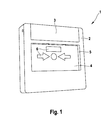
- the FIG. 1 shows in a schematic three-dimensional view obliquely from the front of a manual call point 1, which may for example be part of a complex fire alarm system.
- the manual call point detector 1 comprises a housing 2, which in plan view shows a square or rectangular basic shape and in the edge side a cover cap 3 and in the middle a glass plate 4 is arranged.
- the glass plate 4 covers from the inside of the housing 2 from a front window 5 of the housing, which has a rectangular basic shape, wherein the height of the window 5 between one third and half the height of the housing 2 makes up and the width of the window 5 to projecting edge strip extends over the entire width of the housing 2.
- the glass pane 4 To trigger the manual call point 1, the glass pane 4 must be broken by application of force, already breaking the glass plate 4 is sufficient to trigger the manual call point 1.
- areas 6 e.g. are formed as windows and / or normeetice symbols or pictograms, the background color, as will be explained in detail later.
- the manual fire detector 1 is in the untreated state with a arranged behind the glass 4 homogeneous background and in the tripped state by color highlighted areas 6.
- by striking the glass 4 a arranged inside the housing 2 switching element (not shown) triggered, which sends an electrical signal.
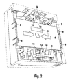
- FIG. 2 shows a schematic three-dimensional view into the housing 2 of the manual call point 1, wherein a lower housing part 7, which is for example formed as an integrally molded injection molded part, can be seen with a plurality of functional components used.
- the glass 4 which has a rectangular basic shape and is held laterally via fastening clips 8.
- the manual call point detector 1 also has a sliding plate 9, which is arranged parallel to the glass plate 4 in the interior of the housing.
- the sliding plate 9 is slidably mounted between a normal position and a reporting position along the direction of arrow 10.
- the normal position corresponds to the unreleased state of the manual call point detector 1, whereas the message position corresponds to the tripped state.
- a spring device 11 which biases the slide plate 9 in the direction 10.
- the sliding plate 9 In the normal position, the sliding plate 9 is, however, with a strip-like extension 12 on a side edge, in FIG. 2 on the lower edge of the glass pane 4, so that the sliding movement is positively locked.
- the glass plate 4 On the opposite side edge of the glass sheet 4, in FIG. 2 the upper edge, the glass plate 4 with the narrow side 13 of a support block 14 in Appendix.
- the sliding plate 9 is supported in the displacement direction 10 via the strip-like shoulder 12 at the lower edge of the glass plate 4, wherein the glass plate 4 is supported in the same direction with the upper edge on the narrow side 13 of the support block 14.
- the manual call point 1 can be dismantled or opened and the switching element, not shown, manually triggered. After this procedure, however, is not completely ruled out that the manual call point 1 is inoperative during subsequent assembly, the points in the FIGS. 1 and 2 shown hand fire detector 1 a test mechanism that allows a test of the manual call point 1 without opening the housing 2 and without destroying the glass plate 4.
- the test mechanism is realized in that the support block 14 is mounted rotatably and optionally displaceable and can be operated with the housing 2 closed.
- FIG. 3 shows the manual fire detector 1 in a test-release, wherein the glass plate 4, in contrast to the preceding figures diagrammatically transparent is shown.
- the support block 14 is rotated about a centrally disposed axis of rotation perpendicular to the surface extension of the glass plate 4, so that the glass plate 4 rests in the final state on a longitudinal side 15 of the support block 14.
- a displacement against the displacement direction 10 to solve a lock is necessary to unlock the support block 14, so that a deliberate false triggering of the manual call point 1 is made difficult by unauthorized persons.
- Due to the bias of the sliding plate 9, the glass plate 4 is offset in the sliding direction 10 together with the sliding plate 9, wherein the sliding plate 9, the switching element, not shown, is triggered.
- the glass plate 4 is supported in each case by the support block parallel to the overlying edge , in addition, it is necessary in the transition from the normal state to the test state of the support block 14 that an actuation resistance due to the corner regions of the support block 14 must be overcome, since first the glass 4 and the slide plate 9 must be moved against the direction of displacement 10.
- the support block 14 from outside the housing 2 is actuated.
- the support block 14 has a mechanical interface 16, which is formed as an oval or elliptical recess with a central mandrel in the support block 14 and via a slot-like or oval opening 17 which is arranged in the housing 2 behind the cover plate 3 is reachable. Due to the special design of the mechanical interface 16 ensures that a test-release can only be achieved by a special tool, which has a matched to the mechanical interface 16 functional section, and not, for example, with a commercially available screwdriver. This measure complicates a deliberate false triggering of the manual call point 1 by unauthorized persons.
- the shutter has two receiving openings 18, which are arranged on the upper edge of the window 5 and the beginning of Form guide channels.
- the guide channels extend in the course initially protected within the housing 2 and are open in an area below the cap 3 to the outside.
- the guide channels allow the insertion of angled, nose-like domes of a special tool, wherein the end portions of the nose-like dome extend to the outwardly open areas.
- Such a special tool 19 is shown, which engages with the angled, nose-like, parallel to each other arranged domes 20 in the receiving openings 18, so that by means of a lifting movement, the cap 3 can be levered.
- the special tool 19 has at one end the dome 20 as functional elements for levering the cap 3. At another end, a special key 21 for actuating the support block 14 is formed with a correspondingly adapted, oval cross section with a central recess. At a third end, the special tool 19 on a push rod 22, which is adapted to move the slide plate 9 from the reporting position to the normal position, as shown in the FIG. 3 is shown.
Landscapes
- Business, Economics & Management (AREA)
- Emergency Management (AREA)
- Physics & Mathematics (AREA)
- General Physics & Mathematics (AREA)
- Fire Alarms (AREA)
- Alarm Systems (AREA)
- Burglar Alarm Systems (AREA)
Abstract
Description
Die Erfindung betrifft eine Meldevorrichtung mit manueller Auslösung, insbesondere einen Handfeuermelder, mit einem Gehäuse und mit einem zerbrechlichen Element, welches das Gehäuse bedienseitig zum Benutzer abschließt und welches zur manuellen Auslösung der Meldevorrichtung durch den Benutzer zerbrochen werden muss.The invention relates to a message device with manual release, in particular a manual call point, with a housing and with a fragile element which closes the housing operator side to the user and which must be broken for manual activation of the reporting device by the user.
Handfeuermelder sind Komponenten von oftmals komplexen Feuermeldeanlagen und erlauben einem Benutzer, durch manuelle Betätigung einen Feueralarm auszulösen. Die Handfeuermelder sind zum Beispiel in der Norm EN 54-11 geregelt, wobei zwischen einem Typ A und einem Typ B unterschieden wird. Bei der Bauart Typ A wird ein Alarm durch Zerstören oder auch Verschieben eines Elements ausgelöst. Bei der Bauart Typ B ist zusätzlich die manuelle Betätigung eines Auslöseelements, zum Beispiel eines Druckknopfes, erforderlich.Manual call points are components of often complex fire detection systems and allow a user to trigger a fire alarm by manual operation. The manual call points are regulated, for example, in the standard EN 54-11, whereby a distinction is made between a type A and a type B. In type A design, an alarm is triggered by destroying or even moving an element. In the type B type, the manual operation of a trigger element, for example a push button, is additionally required.
Einen allgemeinen Stand der Technik zu Handfeuermeldern bildet die Offenlegungsschrift
Offenbarung der ErfindungDisclosure of the invention
Im Rahmen der Erfindung wird eine Meldevorrichtung mit den Merkmalen des Anspruchs 1 und ein Spezialschlüssel mit den Merkmalen des Anspruchs 14 optional in Kombination mit der Meldevorrichtung vorgeschlagen. Bevorzugte oder vorteilhafte Ausführungsformen der Erfindung ergeben sich aus den Unteransprüchen, der nachfolgenden Beschreibung und den beigefügten Figuren.In the context of the invention, a reporting device with the features of
Erfindungsgemäß wird eine Meldevorrichtung mit manueller Auslösung, insbesondere ein Handfeuermelder und/oder ein Branddruckknopfmelder vorgeschlagen, die vorzugsweise konform zu der Norm EN 54-11, insbesondere im Hinblick auf die Typen A und B mit einem zerbrechlichen Element ausgebildet ist. Derartige Meldevorrichtungen werden beispielsweise als Komponenten in komplexen Feuermeldeanlagen eingesetzt, die in Gebäuden oder öffentlichen Plätzen installiert sind.According to the invention, a manual release alarm device is proposed, in particular a manual call point indicator and / or a fire push button detector, which is preferably designed in conformity with the standard EN 54-11, in particular with regard to the types A and B with a frangible element. Such signaling devices are used, for example, as components in complex fire detection systems installed in buildings or public places.
Die Meldevorrichtung weist ein Gehäuse auf, welches beispielsweise als ein Gehäuseunterteil mit einer schwenkbaren Tür oder ein Gehäuseunterteil mit einem abnehmbaren Deckel ausgebildet ist. Das Gehäuse ist bedienseits zum Benutzer mit einem zerbrechlichen Element abgeschlossen. Das zerbrechliche Element ist vorzugsweise plattenförmig oder als Platte ausgebildet und insbesondere aus Glas oder Kunststoff gefertigt. Für den Fall einer Kunststoffscheibe weist diese bevorzugt Sollbruchstellen auf, so dass diese bei einer manuellen Auslösung durch den Benutzer in vorbestimmte Teilstücke zerfällt. Die Meldevorrichtung ist derart ausgebildet, dass bei einer manuellen Auslösung der Meldevorrichtung durch den Benutzer das zerbrechliche Element bestimmungsgemäß zerbrochen wird.The signaling device has a housing which is designed, for example, as a housing lower part with a pivotable door or a housing lower part with a removable cover. The housing is user-terminated with a fragile element. The fragile element is preferably plate-shaped or formed as a plate and in particular made of glass or plastic. In the case of a plastic disc, this preferably has predetermined breaking points, so that these decays into predetermined portions upon manual activation by the user. The signaling device is designed such that upon manual triggering of the signaling device by the user, the fragile element is intentionally broken.
Erfindungsgemäß weist die Meldevorrichtung einen Testmechanismus für einen zerstörungsfreien Funktionstest auf, bei dem insbesondere das zerbrechliche Element nicht zerstört wird. Der Testmechanismus ist dabei ausgebildet und/oder angeordnet, dass der Funktionstest eine Verschiebung des zerbrechlichen Elements umfasst, wobei durch die Verschiebung die Meldevorrichtung aktiviert bzw. ausgelöst wird. Vorzugsweise ist der Funktionstest und das Rücksetzen der Meldevorrichtung ohne ein Austausch von Komponenten möglich.According to the invention, the reporting device has a test mechanism for a nondestructive functional test, in which in particular the fragile element is not destroyed. The test mechanism is embodied and / or arranged in such a way that the functional test comprises a displacement of the fragile element, whereby the signaling device is activated or triggered by the displacement. Preferably, the functional test and the resetting of the signaling device without an exchange of components is possible.
Während bei der Verwendung von rücksetzbaren Elementen ein Funktionstest der Meldevorrichtungen einfach durchgeführt werden kann, indem die Meldevorrichtung ausgelöst und nach dem Auslösen zurückgesetzt wird, wird der Test einer Meldevorrichtung mit einem zerbrechlichen Element bislang beispielsweise durchgeführt, indem das Gehäuse der Meldevorrichtung geöffnet und eine Betätigung der Meldevorrichtung simuliert wird.While, with the use of resettable elements, a functional test of the signaling devices can be easily performed by triggering the signaling device and resetting it after tripping, the test becomes a Message device with a frangible element so far, for example, performed by the housing of the reporting device is opened and an actuation of the reporting device is simulated.
Demgegenüber schlägt die Erfindung einen Testmechanismus vor, welcher das zerbrechliche Element während des Funktionstests bewegt, jedoch ohne das zerbrechliche Element zu zerstören, um auf diese Weise insbesondere bei geschlossenem Gehäuse eine Betätigung anwendungsnah zu simulieren. Damit wird durch die vorliegende Erfindung eine vorteilhafte Meldevorrichtung mit einem zerbrechlichen Element beschrieben, welche in einfacher Weise getestet werden kann, aber dennoch eine hohe Sicherheit gegen gewollte oder ungewollte Fehlauslösung bietet.In contrast, the invention proposes a test mechanism, which moves the fragile element during the functional test, but without destroying the fragile element, in order to simulate in this way, especially with the housing closed actuation application. Thus, the present invention describes an advantageous message device with a frangible element, which can be tested in a simple manner, but nevertheless offers a high degree of security against intentional or unwanted false tripping.
Bei einer bevorzugten Ausführungsform der Erfindung ist der Testmechanismus so ausgebildet, dass während des Funktionstests die Verschiebung des zerbrechlichen Elements entlang einer Ebene erfolgt, welche parallel oder identisch zu der Flächenerstreckung des zerbrechlichen Elements ausgerichtet ist. Die Verschieberichtung des zerbrechlichen Elements ist dabei bevorzugt senkrecht zu der üblichen Betätigungsrichtung der Meldevorrichtung ausgebildet. Mit dieser Ausbildung kann der Testmechanismus in platzsparender Weise in dem Gehäuse der Meldevorrichtung integriert werden.In a preferred embodiment of the invention, the test mechanism is designed such that during the functional test the displacement of the frangible element takes place along a plane that is parallel or identical to the surface extension of the frangible element. The direction of displacement of the fragile element is preferably formed perpendicular to the usual operating direction of the signaling device. With this design, the test mechanism can be integrated in a space-saving manner in the housing of the reporting device.
Die Meldevorrichtung weist vorzugsweise ein Schaltelement auf, welches bei Betätigung eine Meldung abgibt, wobei das Schaltelement mittelbar oder unmittelbar durch das zerbrechliche Element betätigt wird. In dem erstgenannten Fall wird das Schaltelement somit direkt durch das zerbrechliche Element ausgelöst, beispielsweise indem das Schaltelement und das zerbrechliche Element eine gemeinsame Berührungsfläche aufweisen. In dem zweiten Fall wird die Bewegung des zerbrechlichen Elements über mindestens ein Zwischenglied auf das Schaltelement übertragen, um dieses zu schalten bzw. zu betätigen.The signaling device preferably has a switching element which emits a message when actuated, wherein the switching element is actuated directly or indirectly by the frangible element. In the former case, the switching element is thus triggered directly by the fragile element, for example by the switching element and the fragile element having a common contact surface. In the second case, the movement of the frangible element is transmitted via at least one intermediate member to the switching element in order to switch or actuate this.
Bei einer besonders bevorzugten Ausführungsform ist dieses Zwischenglied als eine Schiebeplatte ausgebildet, die das Schaltelement vorzugsweise unmittelbar betätigt. Die Schiebeplatte ist in dem Gehäuse zwischen einer Normalposition - in einem unausgelösten Zustand der Meldevorrichtung - und einer Meldeposition - in einem ausgelösten Zustand der Meldevorrichtung - verschiebbar angeordnet. In der Normalposition ist die Schiebeplatte durch das zerbrechliche Element formschlüssig gehalten, wobei vorzugsweise vorgesehen ist, dass die Schiebeplatte durch eine Gewichtskraft oder eine Federkraft vorgespannt ist. Schiebeplatte und zerbrechliches Element sind dabei derart gekoppelt, dass durch die Verschiebung des zerbrechlichen Elements die Schiebeplatte in die Meldeposition überführbar ist und/oder überführt wird.In a particularly preferred embodiment, this intermediate member is formed as a sliding plate, which preferably operates the switching element directly. The sliding plate is slidably disposed in the housing between a normal position - in an unresolved state of the signaling device - and a reporting position - in a triggered state of the signaling device. In the Normal position, the sliding plate is positively held by the fragile element, wherein it is preferably provided that the sliding plate is biased by a weight force or a spring force. Sliding plate and fragile element are coupled in such a way that the sliding plate can be transferred to the reporting position and / or transferred by the displacement of the fragile element.
Bei einer bevorzugten praktischen Realisierung der Erfindung umfasst der Testmechanismus einen Auflageblock, auf dem das zerbrechliche Element aufliegt und der die Verschiebung steuert, wobei das zerbrechliche Element vorzugsweise mit einer freien Seitenkante, insbesondere linienförmig auf dem Auflageblock aufliegt.In a preferred practical realization of the invention, the test mechanism comprises a support block, on which rests the fragile element and controls the displacement, wherein the fragile element preferably rests with a free side edge, in particular linearly on the support block.
Um die Verschiebung des zerbrechlichen Elements zu erreichen, ist der Auflageblock bewegbar, insbesondere verschiebbar und/oder drehbar ausgebildet. Insbesondere weist der Auflageblock eine Normalauflagefläche und eine Testauflagefläche auf. Liegt das zerbrechliche Element auf der Normalauflagefläche auf, so befindet sich die gegebenenfalls vorhandene Schiebeplatte in der Normalposition. Liegt das zerbrechliche Element dagegen auf der Testauflagefläche auf, so ist das zerbrechliche Element bereits verschoben, so dass die gegebenenfalls vorhandene Schiebeplatte in der Meldeposition angeordnet ist. Besonders bevorzugt ist es, wenn der Wechsel der Auflagefläche von der Normalauflagefläche zu der Testauflagefläche durch eine Drehung des Auflageblocks, insbesondere um eine Drehachse senkrecht zur Flächenerstreckung des zerbrechlichen Elements umsetzbar ist bzw. umgesetzt ist.In order to achieve the displacement of the fragile element, the support block is movable, in particular displaceable and / or rotatable. In particular, the support block has a normal support surface and a test support surface. If the fragile element lies on the normal support surface, then the optionally existing sliding plate is in the normal position. On the other hand, if the fragile element lies on the test support surface, then the fragile element is already displaced, so that the optionally present sliding plate is arranged in the reporting position. It is particularly preferred if the change of the support surface from the normal support surface to the test support surface can be implemented or implemented by a rotation of the support block, in particular about a rotation axis perpendicular to the surface extension of the fragile element.
Bei einer vorteilhaften und insbesondere konstruktiv einfachen Ausführungsform weist der Auflageblock im Querschnitt eine Rechtecksform auf bzw. ist als abgerundetes Rechteck ausgebildet, wobei die Normalauflagefläche an einer Schmalseite und die Testauflagefläche an einer Längsseite angeordnet sind. Diese konstruktiv einfach ausführbare Ausbildung der Erfindung hat den Vorteil, dass das zerbrechliche Element sowohl im Normalzustand als auch im Testzustand durch definierte Auflageflächen stets waagrecht gehalten wird und/oder linienförmig aufliegt. Zudem hat die besondere Ausbildungsform des Auflageblocks den Vorteil, dass eine gewisse Kraft zur Betätigung aufgebracht werden muss. Dies ist dadurch begründet, dass das zerbrechliche Element zunächst gegen die eigentliche Verschieberichtung ausgelenkt wird, da aufgrund der Drehung des Auflageblocks das zerbrechliche Element über die Diagonale oder den Eckbereich des Auflageblocks geführt wird.In an advantageous and in particular structurally simple embodiment, the support block has a rectangular shape in cross-section or is formed as a rounded rectangle, wherein the normal support surface are arranged on a narrow side and the test support surface on a longitudinal side. This structurally simple embodiment of the invention has the advantage that the fragile element is always kept horizontal in the normal state and in the test state by defined bearing surfaces and / or rests linear. In addition, the particular embodiment of the support block has the advantage that a certain force must be applied to the operation. This is due to the fact that the fragile element is initially deflected against the actual displacement direction, since due to the rotation of the support block, the fragile element is guided over the diagonal or the corner region of the support block.
Bei einer Weiterbildung der Erfindung muss der Auflageblock zum Testen gedreht und verschoben werden, wobei durch die kombinierte Schiebe-/Drehbewegung ein versehentliches Auslösen nahezu ausgeschlossen wird.In a further development of the invention, the support block must be rotated and moved for testing, with accidentally triggered by the combined sliding / rotary motion is almost impossible.
Zur Betätigung des Testmechanismus ist es bevorzugt, dass dieser eine mechanische Schnittstelle aufweist, welche ausschließlich durch einen Spezialschlüsselabschnitt betätigt werden kann, wohingegen eine Betätigung durch Standardwerkzeuge blockiert oder verhindert ist. Diese mechanische Schnittstelle kann beispielsweise als eine ovale Öffnung mit einem mittigen Haltedorn ausgeführt sein, so dass der Testmechanismus nur durch den daran angepassten Spezialschlüsselabschnitt ausgelöst werden kann, jedoch ein Auslösen durch zum Beispiel Schraubendreher etc. nicht möglich ist.To operate the test mechanism, it is preferred that it has a mechanical interface which can be actuated exclusively by a special key section, whereas an actuation by standard tools is blocked or prevented. This mechanical interface can be designed, for example, as an oval opening with a central retaining mandrel, so that the test mechanism can only be triggered by the special key section adapted to it, but triggering by, for example, a screwdriver etc. is not possible.
Ein optionaler, weiterer Schutz gegen eine gewollte Fehlauslösung, also insbesondere gegen Vandalismus, ist dadurch gegeben, dass die mechanische Schnittstelle durch eine Abdeckkappe gesichert ist, wobei die Abdeckkappe und/oder die Meldevorrichtung einen Verschluss aufweist bzw. gemeinsam bilden, der bestimmungsgemäß nur mit einem weiteren Spezialschlüsselabschnitt zu öffnen ist. Dabei kann die Abdeckkappe entweder vollständig abnehmbar oder an dem Gehäuse der Meldevorrichtung angelenkt sein, so dass diese weggeschwenkt werden kann. Bei einer bevorzugten Realisierung der Erfindung umfasst der Verschluss insbesondere zwei Aufnahmeöffnungen in dem Gehäuse, in die zwei nasenförmige Fortsätze des weiteren Spezialschlüsselabschnitts eingreifen können, um die Abdeckkappe abzuhebeln.An optional, further protection against intentional false tripping, so in particular against vandalism, is given by the fact that the mechanical interface is secured by a cap, wherein the cap and / or the reporting device has a closure or together form the intended purpose only with a another special key section is open. In this case, the cap can be either completely removable or hinged to the housing of the reporting device, so that it can be swung away. In a preferred embodiment of the invention, the closure comprises in particular two receiving openings in the housing, in which two nose-shaped extensions of the further special key section can engage in order to pry off the covering cap.
Ein weiterer Gegenstand der Erfindung betrifft einen Spezialschlüssel, welcher den Spezialschlüsselabschnitt und den weiteren Spezialschlüsselabschnitt aufweist, wobei die Abschnitte ausgebildet sind, bestimmungsgemäß die Schnittstelle des Testmechanismus bzw. den Verschluss der Abdeckkappe zu bedienen.Another object of the invention relates to a special key, which has the special key portion and the other special key portion, wherein the portions are designed to serve the interface of the test mechanism or the closure of the cap as intended.
Optional ist die Meldevorrichtung umrüstbar ausgebildet, wobei die Schiebeplatte Anformungen aufweist, welche ausgebildet sind, formschlüssig mit einem rücksetzbaren Element, welches statt dem zerbrechlichen Element eingesetzt ist, zusammenzuwirken, so dass eine Betätigung des rücksetzbaren Elements zu einer Verschiebung der Schiebeplatte von der Normalposition in eine Meldeposition führt. Insbesondere für ein Rücksetzen der Schiebeplatte, aber optional auch für die Montage des zerbrechlichen Elements, weist der Spezialschlüssel einen dritten Spezialschlüsselabschnitt auf, der als Schiebestange ausgebildet ist. Meldevorrichtung und Spezialschlüssel sind derart aneinander angepasst, dass der dritte Spezialschlüsselabschnitt durch eine Gehäuseöffnung in das insbesondere geschlossene Gehäuse einführbar ist und eine Verschiebung der Schiebeplatte gegen die Verschieberichtung bewirkt.Optionally, the signaling device is convertible, wherein the sliding plate has projections which are designed to interact positively with a resettable element, which is used instead of the frangible element, so that an actuation of the resettable element to a displacement of the sliding plate from the normal position into a Message position leads. In particular, for a reset of the sliding plate, but optionally also for the mounting of the fragile element, the Special key on a third special key section, which is designed as a push rod. Message device and special key are adapted to each other that the third special key portion is inserted through a housing opening in the particular closed housing and causes a displacement of the sliding plate against the displacement direction.
Ein weiterer Gegenstand der Erfindung betrifft ein Verfahren zum zerstörungsfreien Testen der Funktion der Meldevorrichtung gemäß den Merkmalen des unabhängigen Anspruchs 16.Another object of the invention relates to a method for non-destructive testing of the function of the reporting device according to the features of
Weitere Merkmale, Vorteile und Wirkungen der Erfindung ergeben sich aus der nachfolgenden Beschreibung und den Figuren eines bevorzugten Ausführungsbeispiels. Dabei zeigen:
Figur 1- eine schematische, dreidimensionale Draufsicht schräg von vorne auf einen Handfeuermelder als ein Ausführungsbeispiel der Erfindung;
Figur 2- eine schematische, dreidimensionale Draufsicht schräg von vorne in den geöffneten Handfeuermelder in
Figur 1 Figur 3- eine ähnliche Ansicht wie in
Figur 2 Figur 4- den geschlossenen Handfeuermelder in gleicher Darstellung wie in der
Figur 1 Figur 5- den geschlossenen Handfeuermelder in
Figur 1
- FIG. 1
- a schematic, three-dimensional plan view obliquely from the front of a manual call point as an embodiment of the invention;
- FIG. 2
- a schematic, three-dimensional plan view obliquely from the front in the open manual call point in
FIG. 1 ; - FIG. 3
- a similar view as in
FIG. 2 in the manual call point during the operation of the test mechanism; - FIG. 4
- the closed manual call point in the same representation as in the
FIG. 1 with removed cap; - FIG. 5
- the closed manual call point in
FIG. 1 in the same representation with attached special key for opening the cap.
Einander entsprechende Teile oder Größen sind in den Figuren mit einander entsprechenden oder gleichen Bezugszeichen versehen.Corresponding parts or sizes are provided in the figures with corresponding or identical reference numerals.
Die
Zur Auslösung des Handfeuermelders 1 muss die Glasscheibe 4 durch Kraftaufwendung zerbrochen werden, wobei bereits das Zerbrechen der Glasscheibe 4 ausreicht, um den Handfeuermelder 1 auszulösen. Optional wechseln zur Quittierung der erfolgten Auslösung innerhalb des Gehäuses 2 in Bereichen 6, die z.B. als Fenster und/oder normentsprechende Symbole bzw. Piktogramme ausgebildet sind, die Hintergrundfarbe, wie dies später noch ausführlich erläutert wird. Somit zeigt sich der Handfeuermelder 1 in dem unausgelösten Zustand mit einem hinter der Glasscheibe 4 angeordneten homogenen Hintergrund und in dem ausgelösten Zustand durch farblich hervorgehobene Bereiche 6. Zudem wird durch das Einschlagen der Glasscheibe 4 ein im Inneren des Gehäuses 2 angeordnetes Schaltelement (nicht gezeigt) ausgelöst, welches ein elektrisches Meldesignal absetzt.To trigger the
Die
In der Normalposition liegt die Schiebeplatte 9 jedoch mit einem leistenähnlichen Fortsatz 12 auf einer Seitenkante, in
Bei einem Übergang von dem unausgelösten Zustand in den ausgelösten Zustand wird die Glasplatte 4 als zerbrechliches Element durch Krafteinwirkung zerstört, wobei sowohl der Formschluss zwischen Glasplatte 4 und Auflageblock 14 und der Formschluss zwischen Schiebeplatte 9 und Glasplatte 4 aufgehoben wird. Als Folge des aufgehobenen Formschlusses verschiebt sich die Schiebeplatte 9 unter Krafteinwirkung der Federeinrichtung 11 in Schieberichtung 10 und wechselt von der Normalposition in die Meldeposition. Bei diesem Wechsel wird ein nicht dargestelltes Schaltelement, welches beispielsweise als Mikroschalter ausgebildet ist, betätigt und eine Meldung abgesetzt und optional zugleich der Hintergrund der Bereiche 6 farblich geändert.In a transition from the unresolved state in the tripped state, the
Zur Durchführung eines Funktionstests, um die Funktionsfähigkeit des Handfeuermelders 1 bzw. dessen Anschluss in einer Feuermeldeanlage zu überprüfen, kann der Handfeuermelder 1 demontiert bzw. geöffnet und das nicht dargestellte Schaltelement manuell ausgelöst werden. Nachdem bei dieser Vorgehensweise jedoch nicht restlos auszuschließen ist, dass der Handfeuermelder 1 bei der nachfolgenden Montage funktionsuntüchtig wird, weist der in den
Die
Wie sich aus der
Zur weiteren Sicherung gegen eine gewollte Fehlauslösung ist die Abdeckkappe 3 bzw. das Gehäuse 2 mit einem Verschluss gesichert, welcher ebenfalls nur mit einem Spezialwerkzeug zu öffnen ist. Der Verschluss weist zwei Aufnahmeöffnungen 18 auf, die an der oberen Kante des Fensters 5 angeordnet sind und die den Beginn von Führungskanälen bilden. Die Führungskanäle erstrecken sich im weiteren Verlauf zunächst geschützt innerhalb des Gehäuses 2 und sind in einem Bereich unterhalb der Abdeckkappe 3 nach außen hin geöffnet. Die Führungskanäle erlauben das Einführen von gewinkelten, nasenartigen Domen eines Spezialwerkzeugs, wobei die Endabschnitte der nasenartigen Dome sich bis zu den nach außen hin geöffneten Bereichen erstrecken. Durch eine Schwenkbewegung der Dome um Auflagepunkte, die jeweils in dem geschützten Bereich der Führungskanäle angeordnet sind, kann die Abdeckkappe 3 aufgehebelt werden.To further protect against a desired false triggering the
In der
Das Spezialwerkzeug 19 weist an einem Ende die Dome 20 als Funktionselemente zum Aufhebeln der Abdeckkappe 3 auf. An einem anderen Ende ist ein Spezialschlüssel 21 zur Betätigung des Auflageblocks 14 mit einem entsprechend angepassten, ovalen Querschnitt mit mittiger Ausnehmung angeformt. An einem dritten Ende weist das Spezialwerkzeug 19 eine Schiebestange 22 auf, welche ausgebildet ist, die Schiebeplatte 9 von der Meldeposition in die Normalposition zu verschieben, wie dies in der
Claims (15)
mit einem Gehäuse (2)
und mit einem zerbrechlichen Element (3), welches das Gehäuse (2) bedienseitig zum Benutzer abschließt und welches zur manuellen Auslösung der Meldevorrichtung (1) durch den Benutzer zerbrochen werden muss,
gekennzeichnet durch
einen Testmechanismus (14) für einen zerstörungsfreien Funktionstest der Meldevorrichtung (1), wobei der Testmechanismus (14) ausgebildet und/oder angeordnet ist, durch eine Verschiebung des zerbrechlichen Elements (4) die Meldevorrichtung (1) testend auszulösen.Signaling device (1) with manual release, in particular manual call point,
with a housing (2)
and with a frangible element (3) which closes the housing (2) to the user on the user side and which must be broken by the user for the manual triggering of the reporting device (1),
marked by
a test mechanism (14) for a nondestructive functional test of the signaling device (1), wherein the test mechanism (14) is formed and / or arranged to trigger by a displacement of the frangible element (4), the reporting device (1) testing.
Applications Claiming Priority (1)
| Application Number | Priority Date | Filing Date | Title |
|---|---|---|---|
| DE200710020282 DE102007020282A1 (en) | 2007-04-30 | 2007-04-30 | Signaling device with test mechanism and special key for actuating the test mechanism |
Publications (3)
| Publication Number | Publication Date |
|---|---|
| EP1988525A2 true EP1988525A2 (en) | 2008-11-05 |
| EP1988525A3 EP1988525A3 (en) | 2010-01-06 |
| EP1988525B1 EP1988525B1 (en) | 2015-09-23 |
Family
ID=39645509
Family Applications (1)
| Application Number | Title | Priority Date | Filing Date |
|---|---|---|---|
| EP08102694.0A Active EP1988525B1 (en) | 2007-04-30 | 2008-03-18 | Notification device with test mechanism and special key for actuating test mechanism |
Country Status (4)
| Country | Link |
|---|---|
| EP (1) | EP1988525B1 (en) |
| CN (1) | CN101299290B (en) |
| DE (1) | DE102007020282A1 (en) |
| ES (1) | ES2550360T3 (en) |
Cited By (1)
| Publication number | Priority date | Publication date | Assignee | Title |
|---|---|---|---|---|
| US10249175B2 (en) | 2015-09-18 | 2019-04-02 | Gulf Security Technology Company Limited | Push plate of manual alarm device |
Citations (3)
| Publication number | Priority date | Publication date | Assignee | Title |
|---|---|---|---|---|
| EP1503390A2 (en) | 2003-07-30 | 2005-02-02 | CQR Security Components Limited | Call point for an alarm system |
| EP1288881B1 (en) | 2001-09-03 | 2005-05-18 | Siemens Building Technologies AG | Hand-operated emergency alarm signal box |
| EP1632921B1 (en) | 2004-09-02 | 2009-11-11 | Novar GmbH | Manual hazard warning device |
Family Cites Families (2)
| Publication number | Priority date | Publication date | Assignee | Title |
|---|---|---|---|---|
| DE19835318B4 (en) | 1998-02-02 | 2007-07-26 | Robert Bosch Gmbh | Manually operated detectors |
| GB2401992B (en) * | 2003-05-17 | 2006-12-13 | Kac Alarm Company Ltd | Call points |
-
2007
- 2007-04-30 DE DE200710020282 patent/DE102007020282A1/en not_active Withdrawn
-
2008
- 2008-03-18 ES ES08102694.0T patent/ES2550360T3/en active Active
- 2008-03-18 EP EP08102694.0A patent/EP1988525B1/en active Active
- 2008-04-30 CN CN200810095999.7A patent/CN101299290B/en active Active
Patent Citations (3)
| Publication number | Priority date | Publication date | Assignee | Title |
|---|---|---|---|---|
| EP1288881B1 (en) | 2001-09-03 | 2005-05-18 | Siemens Building Technologies AG | Hand-operated emergency alarm signal box |
| EP1503390A2 (en) | 2003-07-30 | 2005-02-02 | CQR Security Components Limited | Call point for an alarm system |
| EP1632921B1 (en) | 2004-09-02 | 2009-11-11 | Novar GmbH | Manual hazard warning device |
Cited By (1)
| Publication number | Priority date | Publication date | Assignee | Title |
|---|---|---|---|---|
| US10249175B2 (en) | 2015-09-18 | 2019-04-02 | Gulf Security Technology Company Limited | Push plate of manual alarm device |
Also Published As
| Publication number | Publication date |
|---|---|
| DE102007020282A1 (en) | 2008-11-06 |
| CN101299290A (en) | 2008-11-05 |
| EP1988525B1 (en) | 2015-09-23 |
| EP1988525A3 (en) | 2010-01-06 |
| CN101299290B (en) | 2016-01-06 |
| ES2550360T3 (en) | 2015-11-06 |
Similar Documents
| Publication | Publication Date | Title |
|---|---|---|
| EP0744002B1 (en) | Alarm-triggering locking device for the catch and/or hinge region of a door or window to be protected | |
| DE3101791C2 (en) | ||
| DE4033840A1 (en) | Emergency exit door opening system - uses release spring acting on toggle lever mechanism for opening each locking element under electric control | |
| EP2058460B9 (en) | Anti-tamper locking device for building | |
| DE19633628A1 (en) | Readiness switching of burglar alarm system | |
| EP1988525B1 (en) | Notification device with test mechanism and special key for actuating test mechanism | |
| EP0779945B1 (en) | Alarm-triggering closure device for the closure and/or hinge area of a door or window to be made secure | |
| DE19603679C5 (en) | Locking device for windows or doors that triggers an alarm | |
| DE102006046839B4 (en) | Fire button alarm | |
| DE10006946C2 (en) | Strike plate that triggers the alarm | |
| DE19714594C2 (en) | Alarm-triggering striking plate for the locking area of a door or window to be secured | |
| DE2814548A1 (en) | SAFETY LOCK DEVICE | |
| EP1580363B1 (en) | Device for securing or surveillance of emergency exits or similar | |
| DE202019100117U1 (en) | Device for opening and closing a door | |
| DE2455031C2 (en) | SAFETY SWITCH | |
| EP1618581B1 (en) | Locking element for an electrical device | |
| EP1988524B1 (en) | Notification device with manual disengagement and alarm display | |
| WO2015169952A1 (en) | Device for triggering an alarm and for securing a window or door against intrusion | |
| CH703642B1 (en) | Arrangement for monitoring of the shutter members. | |
| AT509234B1 (en) | MONITORING FOR THE OPENING STATUS OF A WINDOW OR DOOR | |
| DE219746C (en) | ||
| DE3227876A1 (en) | Alarm system for protecting a passage | |
| DE19505856A1 (en) | Alarm activating retention system for lock and/or hinge region of door or window | |
| DE202018101393U1 (en) | Escape door arrangement | |
| DE19647854A1 (en) | Profile cylinder for doors of building |
Legal Events
| Date | Code | Title | Description |
|---|---|---|---|
| PUAI | Public reference made under article 153(3) epc to a published international application that has entered the european phase |
Free format text: ORIGINAL CODE: 0009012 |
|
| AK | Designated contracting states |
Kind code of ref document: A2 Designated state(s): AT BE BG CH CY CZ DE DK EE ES FI FR GB GR HR HU IE IS IT LI LT LU LV MC MT NL NO PL PT RO SE SI SK TR |
|
| AX | Request for extension of the european patent |
Extension state: AL BA MK RS |
|
| PUAL | Search report despatched |
Free format text: ORIGINAL CODE: 0009013 |
|
| AK | Designated contracting states |
Kind code of ref document: A3 Designated state(s): AT BE BG CH CY CZ DE DK EE ES FI FR GB GR HR HU IE IS IT LI LT LU LV MC MT NL NO PL PT RO SE SI SK TR |
|
| AX | Request for extension of the european patent |
Extension state: AL BA MK RS |
|
| 17P | Request for examination filed |
Effective date: 20100706 |
|
| AKX | Designation fees paid |
Designated state(s): DE ES GB IT |
|
| 17Q | First examination report despatched |
Effective date: 20100826 |
|
| GRAP | Despatch of communication of intention to grant a patent |
Free format text: ORIGINAL CODE: EPIDOSNIGR1 |
|
| GRAJ | Information related to disapproval of communication of intention to grant by the applicant or resumption of examination proceedings by the epo deleted |
Free format text: ORIGINAL CODE: EPIDOSDIGR1 |
|
| GRAP | Despatch of communication of intention to grant a patent |
Free format text: ORIGINAL CODE: EPIDOSNIGR1 |
|
| INTG | Intention to grant announced |
Effective date: 20150605 |
|
| INTG | Intention to grant announced |
Effective date: 20150625 |
|
| GRAS | Grant fee paid |
Free format text: ORIGINAL CODE: EPIDOSNIGR3 |
|
| GRAA | (expected) grant |
Free format text: ORIGINAL CODE: 0009210 |
|
| AK | Designated contracting states |
Kind code of ref document: B1 Designated state(s): DE ES GB IT |
|
| REG | Reference to a national code |
Ref country code: GB Ref legal event code: FG4D Free format text: NOT ENGLISH |
|
| REG | Reference to a national code |
Ref country code: DE Ref legal event code: R096 Ref document number: 502008013398 Country of ref document: DE |
|
| REG | Reference to a national code |
Ref country code: ES Ref legal event code: FG2A Ref document number: 2550360 Country of ref document: ES Kind code of ref document: T3 Effective date: 20151106 |
|
| REG | Reference to a national code |
Ref country code: DE Ref legal event code: R097 Ref document number: 502008013398 Country of ref document: DE |
|
| PLBE | No opposition filed within time limit |
Free format text: ORIGINAL CODE: 0009261 |
|
| STAA | Information on the status of an ep patent application or granted ep patent |
Free format text: STATUS: NO OPPOSITION FILED WITHIN TIME LIMIT |
|
| 26N | No opposition filed |
Effective date: 20160624 |
|
| PGFP | Annual fee paid to national office [announced via postgrant information from national office to epo] |
Ref country code: IT Payment date: 20230331 Year of fee payment: 16 Ref country code: ES Payment date: 20230414 Year of fee payment: 16 Ref country code: DE Payment date: 20230524 Year of fee payment: 16 |
|
| PGFP | Annual fee paid to national office [announced via postgrant information from national office to epo] |
Ref country code: GB Payment date: 20240322 Year of fee payment: 17 |