EP1988296A1 - Variations of the closing speed of a valve by using severals throttling apertures - Google Patents
Variations of the closing speed of a valve by using severals throttling apertures Download PDFInfo
- Publication number
- EP1988296A1 EP1988296A1 EP07008908A EP07008908A EP1988296A1 EP 1988296 A1 EP1988296 A1 EP 1988296A1 EP 07008908 A EP07008908 A EP 07008908A EP 07008908 A EP07008908 A EP 07008908A EP 1988296 A1 EP1988296 A1 EP 1988296A1
- Authority
- EP
- European Patent Office
- Prior art keywords
- quick
- valve
- closing
- closure element
- flow
- Prior art date
- Legal status (The legal status is an assumption and is not a legal conclusion. Google has not performed a legal analysis and makes no representation as to the accuracy of the status listed.)
- Withdrawn
Links
Images


Classifications
-
- F—MECHANICAL ENGINEERING; LIGHTING; HEATING; WEAPONS; BLASTING
- F16—ENGINEERING ELEMENTS AND UNITS; GENERAL MEASURES FOR PRODUCING AND MAINTAINING EFFECTIVE FUNCTIONING OF MACHINES OR INSTALLATIONS; THERMAL INSULATION IN GENERAL
- F16K—VALVES; TAPS; COCKS; ACTUATING-FLOATS; DEVICES FOR VENTING OR AERATING
- F16K31/00—Actuating devices; Operating means; Releasing devices
- F16K31/44—Mechanical actuating means
- F16K31/56—Mechanical actuating means without stable intermediate position, e.g. with snap action
-
- F—MECHANICAL ENGINEERING; LIGHTING; HEATING; WEAPONS; BLASTING
- F15—FLUID-PRESSURE ACTUATORS; HYDRAULICS OR PNEUMATICS IN GENERAL
- F15B—SYSTEMS ACTING BY MEANS OF FLUIDS IN GENERAL; FLUID-PRESSURE ACTUATORS, e.g. SERVOMOTORS; DETAILS OF FLUID-PRESSURE SYSTEMS, NOT OTHERWISE PROVIDED FOR
- F15B15/00—Fluid-actuated devices for displacing a member from one position to another; Gearing associated therewith
- F15B15/20—Other details, e.g. assembly with regulating devices
- F15B15/22—Other details, e.g. assembly with regulating devices for accelerating or decelerating the stroke
- F15B15/224—Other details, e.g. assembly with regulating devices for accelerating or decelerating the stroke having a piston which closes off fluid outlets in the cylinder bore by its own movement
-
- F—MECHANICAL ENGINEERING; LIGHTING; HEATING; WEAPONS; BLASTING
- F16—ENGINEERING ELEMENTS AND UNITS; GENERAL MEASURES FOR PRODUCING AND MAINTAINING EFFECTIVE FUNCTIONING OF MACHINES OR INSTALLATIONS; THERMAL INSULATION IN GENERAL
- F16K—VALVES; TAPS; COCKS; ACTUATING-FLOATS; DEVICES FOR VENTING OR AERATING
- F16K47/00—Means in valves for absorbing fluid energy
- F16K47/02—Means in valves for absorbing fluid energy for preventing water-hammer or noise
- F16K47/023—Means in valves for absorbing fluid energy for preventing water-hammer or noise for preventing water-hammer, e.g. damping of the valve movement
Definitions
- the invention relates to a quick-acting valve, which has a valve drive arranged in an upper housing part, wherein in the upper housing part at least one opening or aperture, which may be integrated in a check valve, is introduced for a control medium, wherein the valve drive has a closure element, and wherein the housing upper part a seen in the vertical direction to the opening spaced aperture is introduced.
- Such quick-acting valves are known and are used, for example, in turbomachines, e.g. Steam turbines used for fast closing of connected to the turbomachine pipes or the like lines.
- Closing the quick-closing valves with a constant closing speed produces a non-linear drop in, for example, the steam mass flow, which under certain circumstances can lead to high pressure shock loads in the connected pipeline.
- This problem occurs, for example, in steam turbines with e.g. four separate valve lines on.
- By failure of a control valve in the closing direction it can happen that three valves are shut off properly, whereas the fourth valve remains open. This results in a much higher steam mass flow through the remaining valve and thus, when shut off by the corresponding quick-closing valve, a much higher pressure surge in the steam line.
- FIG. 1 shows a quick-closing valve 1 in a partial cross-section through a housing upper part 2.
- a valve rod 3 is guided, which carries a closure element 4.
- the closure element 4 can also be referred to as a piston.
- an opening is introduced in the housing upper part 2. Through the opening, a control medium, for example hydraulic oil, can flow into the housing upper part 2. Due to the resulting overpressure, the closure element 4 is moved in the direction of the housing head.
- a control medium for example hydraulic oil
- the closure element 4 takes the valve rod 3 with it.
- the valve rod 3 protrudes into a spring housing, and carries at least one energy accumulator, for example a spiral spring, which is tensioned in accordance with the movement of the valve rod 3.
- the quick-closing valve 1 is open when the energy store is tensioned.
- the excess pressure is reduced by diverting the control medium, so that relaxes the energy storage.
- a bevel 7 arranged in cross-section is arranged so that the upper housing part 2 conically tapers in this inner wall area from the housing head in the direction of the spring housing.
- the closure element 4 has on its outer circumference a bevel 7 corresponding to the slope 8.
- low-pressure hydraulics eg 8 bar
- a diaphragm flow is realized with this configuration.
- the gap 9 becoming progressively smaller in the closing direction 11
- the closing speed of the quick-closing valve 1 slows down FIG. 1 can be used disadvantageously only in the low pressure range (eg 8 bar).
- high pressure hydraulics eg 160 bar
- very small Flow cross sections required so that it would no longer be possible to realize a diaphragm flow.
- FIG. 7 shows another, known quick-closing valve 51 with a combination of the gap flow with a diaphragm flow.
- a step 54 is arranged in the housing inner wall between an opening 52 (screen) and a panel 53 spaced apart in the vertical direction, which cooperates with a corresponding bevel 56 on the closing element 57, so that the disadvantageous gap flow results.
- the closure element 57 is also designed step-like adapted to the step 54 of the housing inner wall.
- FIG. 7 represents the designed in high pressure hydraulic valve drive.
- a diaphragm combination has been selected to realize a cushioning.
- the outlet of the hydraulic oil through two apertures 52, 53. Shortly before impingement of the drive, the flow is closed to the lower in the drawing plane (larger) aperture 53 by a cone (slope 56).
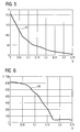
- FIG. 2 shows a linearly extending closing curve 12 wherein the stroke (Y-axis) of the closure element over time (X-axis) is plotted, wherein FIG. 2 refers to a drive for high pressure hydraulics (eg 160 bar).
- FIG. 3 shows FIG. 3 the course of the mass flow 13 during the closing of the quick-closing valve.
- Another disadvantage is that the components must be executed with extreme accuracy, which is virtually unrealizable. Even small manufacturing tolerances cause large changes in relation to the flow velocity of the control medium or the hydraulic oil, and thus to the closing speed of the quick-closing valve.
- the hydraulic oil changes its viscosity due to temperature. However, if the viscosity of the hydraulic oil changes, this also has an immediate effect on its flow velocity and thus also on the closing speed.
- the gap flow is disadvantageously temperature-dependent, which results in that the closing speed is different for cold and warm oil.
- the invention is therefore based on the object to improve a operated with high pressure hydraulic quick-closing valve with simple means to the effect that changed the discharge characteristics of the drive to relieve the steam line is, wherein the closing speed of the quick-closing valve is independent of the temperature of the control medium or the hydraulic oil and piston play or VerMitelement plausible.
- the object is achieved in that the upper housing part has in its interior at least in the range of at least one sequence of two viewed in the vertical direction to the opening spaced diaphragms parallel to its central axis rectilinear guide surface for the closure element with a correspondingly rectilinear closing surface.
- the invention is based on the finding that due to new power plant designs there is a need to use valves with high-pressure hydraulic drive and to adapt the mass flow characteristic to the effect that the resulting characteristic has as shallow a tangent as possible; ie, the requirement is that in FIG. 3 illustrated characteristic to modify that a linear as possible of the steam flow rate can be realized.
- the construction according to FIG. 1 allows adjustment of the valve closing speed to influence the characteristics of the steam mass flow to be shut off in the low pressure hydraulic. However, this is not applicable to the application in high-pressure hydraulics.
- the drive previously used in the field of high-pressure hydraulics ( FIG. 7 ) has a largely linear closing characteristic, which leads to a convex mass flow characteristic. Only in the area before the immediate placement of the cone on the seat cushioning was provided. In the relevant range, this does not affect the mass flow characteristic.
- the realization of the end position damping is not a pure diaphragm flow.
- the production cost of the quick-acting valve according to the invention is also considerably simplified since the originally cooperating bevels and / or steps on the housing inner wall and closure element are omitted. Rather, the housing inner wall or the guide surface and the closing surface of the closure element can be carried out most simply with a constant inner diameter.
- the diaphragms are preferably continuously introduced into the housing wall and connected on the outside to a medium return system or the hydraulic system, which is set to return on closing the quick-acting valve with suitable reactants.
- the at least two diaphragms are each arranged diametrically opposite to the central axis.
- the respective diametrically opposite diaphragms are arranged symmetrically at least with their mouth openings.
- the upper housing part viewed in longitudinal section with respect to its central axis, has on both sides in each case three diaphragms or diaphragm pairs which are in the vertical direction Seen in each case arranged one above the other.
- the at least two apertures in the housing upper part can also be arranged in a circular angle of less than 180 °.
- at least the orifices of the respective successive successive high aperture are each arranged at the same height.
- more than two or three apertures can be provided spaced apart in the vertical direction.
- the principle of the circumferential groove is abandoned with an aperture in the oil flow by means of the invention. Rather, two opposite holes connect the interior with the oil return. In these holes, the actual panels are inserted, preferably screwed. As a result, they can be modified comparatively easily.
- Another advantage is that the gap flow is no longer from one circumferential groove to the next. Now only gap flows with respect to the holes are relevant. The fall but due to the much smaller cross-section almost no longer significant.
- the closure element is connected to a valve rod, which protrudes from the upper side of the housing on the head side and leads to the foot side into a spring housing part adjoining the upper housing part.
- the valve rod On the foot side, the valve rod has a support element for at least one energy store, e.g. for a plate spring, which is supported opposite to the support element on the head side of the spring housing part.
- the closure element is designed as a head-side and foot-side closed cylinder, which is adapted with its cylinder wall or its closing surface to the inner diameter of the guide surface, or with little play on this, wherein the guide surface preferably sealed by a sealing device or seal is to avoid a gap flow.
- the closure element can be designed as a solid cylinder or as a hollow cylinder.
- the closure element also perform like a piston with a piston crown and a piston skirt, wherein the piston head can be arranged oriented either to the foot side or the head side of the valve rod. The piston skirt would then be arranged according to its free end oriented either to the head or to the foot of the valve rod on the piston head.
- the piston skirt is adapted with its diameter to the inner diameter of the guide surface or lies with its closing surface with little play on this.
- the piston skirt is designed as a circumferentially continuous cylinder jacket.
- the piston skirt in the circumferential direction but also be interrupted so that each piston skirt webs are arranged corresponding to the position of the mouth openings of the panels or aperture pairs, and can cover these.
- the cylinder wall of the closure element may be interrupted in the embodiment as a cylinder in the circumferential direction accordingly.
- the hydraulic oil flows through the sequence of the at least two shutters which are spaced from one another in the vertical direction, one of which is covered one after the other by the closing element closing and thus closed.
- the valve drive is thus advantageously braked by successive shut-off of superimposed diaphragms.
- a graduated barrier is thus provided by the apertures which are spaced apart from one another in the vertical direction and subsequently closing, thereby prolonging the closing time, in particular in the lower stroke region of the closure element.
- the stroke decreases steadily when closing or the stroke is smaller.
- the effective flow cross-section is reduced, which has an immediate effect on the outflow velocity of the hydraulic oil and thus affects the closing speed of the quick-acting valve. Both speeds become lower.
- the successive reduction of the closing speed of the valve causes a slowing down of the reduction of the steam mass flow through the quick-closing valve (smaller maximum gradient in the steam mass flow curve) and thus a reduction of the resulting pressure surge in the steam line.
- the closing speed of the quick-closing valves can be varied depending on how many panels are arranged one above the other.
- the more apertures are arranged one above the other or closed or concealed one after the other the longer the closing speed of the valve and thus the characteristic of the steam mass flow can be influenced.
- the arrangement of several superposed diaphragms or diaphragm pairs the characteristic (contour) of the steam mass flow can be influenced.
- a linear decrease in the valve lift causes a convex vapor mass flow curve (see prior art FIGS. 2 and 3 ).
- a concave closing curve for the valve lift is generated by means of a plurality of diaphragms or a plurality of diaphragm pairs.
- the quick-acting valve designed according to the invention has an advantageous effect, which means that a linear decrease of the steam mass flow is effected.
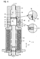
- FIG. 4 shows a quick-closing valve 21, for example, for a steam turbine, which has a arranged in a housing upper part 22 valve drive 23.
- a housing upper part 22 valve drive 23.
- the control medium is preferably hydraulic oil.
- the valve drive 23 has a closure element 26.
- the upper housing part 22 has in the vertical direction (double arrow 27) seen a series of three superimposed aperture pairs 28, 29, 31, and 32, 33, 34 and the aperture 24.
- the successive shutters 28, 29, 31, and 32, 33, 34 are relative to a central axis X of the quick-acting valve 21 diametrically opposite each other, that is arranged symmetrically to each other.
- the two panels 28 and 32 are thus arranged symmetrically to each other in the circumferential direction of the upper housing part 22, and form a diaphragm pair.
- apertures or aperture pairs 29 and 33 or 31 and 34 the same applies.
- the aperture 24 is present only once.
- the diaphragms 28, 29, 31, and 32, 33, 34 in which the diaphragm components are inserted, preferably screwed in, are inserted continuously in the housing upper part 22 and open on the inside into the interior of the housing upper part 22. On the outside, the diaphragms 28, 29 , 31, and 32, 33, 34 connected to a hydraulic system.
- the panels 28, 29, 31, and 32, 33, 34 are preferably arranged perpendicular to the central axis X extending.
- the upper housing part 22 has a cylindrical inner wall 36, which can also be referred to as a guide surface 36 for the closure element 26.
- the guide surface 36 extends in the illustrated embodiment continuously parallel or straight to the central axis X.
- the closure element 26 is connected to a valve rod 37, which protrudes from the upper housing part 22 on the head side and is guided on the foot side into a spring housing part 38.
- the valve rod 37 On the foot side, the valve rod 37 has a support element 39 for at least one energy accumulator 41, wherein the energy accumulator 41 is embodied by way of example as a plate spring, the foot rests on the support member 39 and is supported on the spring housing part 38.
- the closure element 26 is designed as an example of a piston with a piston head 42 and a piston skirt 43.
- the piston head 42 is arranged oriented to the head side of the valve rod 37, wherein the piston skirt 43 is oriented with its free end 44 in the direction of the foot side of the valve rod 37.
- the closure element 26 has an outer diameter, which is adapted to the inner diameter of the guide surface 36, so that the piston skirt 43 or the corresponding portion of the piston crown 42, so the closing surface 46, abuts the guide surface 36 with a small clearance.
- the closure element 26 or the piston head 42 has a sealing device or seal 58, which causes a seal to the guide surface 36.
- the opening 24 is a bore into which a diaphragm is integrated.
- This panel can be integrated in a check valve.
- the quick-closing valve 21 is closed. All diaphragms 28, 29, 31, and 32, 33, 34 are covered or closed by the closing surface 46 of the closure element 26.
- the control medium or the hydraulic oil is passed through the aperture 24 or through the arranged in the inlet check valve, in which the aperture 24 may be integrated, in the interior of the housing upper part 22. Due to the resulting overpressure in the upper housing part 22, the closure element 26 lifts in the direction of the head side, whereby at the same time the support element 39 is raised.
- the energy storage 41 and the diaphragm spring is tensioned.
- the quick-closing valve 21 is opened, the hub has its largest amount.
- the free end 44 of the piston skirt 43 is arranged in the tensioned position above the first aperture 31 and 34 relative to the top side of the upper housing part 22. All seen in the vertical direction and on both sides symmetrically arranged to each other screens 28, 29, 31, and 32, 33, 34 and their mouths are free when the quick-closing valve 21 is open.
- the hydraulic system is set to return. This can be done with suitable reagents.
- the hydraulic oil flows through the orifices 24; 28, 29, 31, and 32, 33, 34 out of the interior of the housing upper part 22, whereby the overpressure is reduced.
- the integration of the lowest in the drawing plane aperture 24 could be provided in a check valve.
- the closure element 26 moves with its piston skirt 43 or its free end 44 in the direction of the foot side. In this downward movement in the plane of the drawing, the piston skirt 43 initially covers the first orifice 31 and 34 simultaneously.
- the following panels 29 and 33 or 28 and 32 are each concealed or closed at the same time. The stroke becomes smaller (lower stroke range), with the stroke having a zero value when the valve is closed.
- the quick-acting valve 21 or its valve drive 23 is operated with high-pressure hydraulics (for example 160 bar).
- high-pressure hydraulics for example 160 bar.
- the flow in the respective aperture 24; 28, 29, 31, and 32, 33, 34 is only dependent on the pressure in the hydraulic oil.
- a temperature dependence (change in viscosity) is largely eliminated by means of the use of the diaphragm flow according to the invention, so that the quick-closing valve 21 closes approximately equally quickly with warm or cold hydraulic oil.
- the valve drive can also be operated with low pressure hydraulics.
- FIG. 5 the closing speed of the quick-acting valve 21 provided with the valve drive 23 according to the invention is shown. It can be seen that, in contrast to the prior art, the closing curve 47 does not run linearly but decreases in a hyperbolic manner. As FIG. 5 can be seen further, only the closing speed in the lower stroke range of the closure element 26 decreases.
- FIG. 6 shows the resulting due to the execution of the invention flow of the mass flow 48 (mass flow characteristic), wherein a to be applied to the mass flow curve 48 tangent significantly flatter than in the prior art (see FIG. 3 ). A similar flat course would result for a linearly closing valve drive ( FIG. 1 ) can only be realized if the total closing time would be significantly increased.
Abstract
Description
Die Erfindung betrifft ein Schnellschlussventil, das einen in einem Gehäuseoberteil angeordneten Ventilantrieb aufweist, wobei in dem Gehäuseoberteil zumindest eine Öffnung bzw. Blende, die in einem Rückschlagventil integriert sein kann, für ein Steuermedium eingebracht ist, wobei der Ventilantrieb ein Verschlusselement aufweist, und wobei in dem Gehäuseoberteil eine in Hochrichtung zur Öffnung gesehen beabstandete Blende eingebracht ist.The invention relates to a quick-acting valve, which has a valve drive arranged in an upper housing part, wherein in the upper housing part at least one opening or aperture, which may be integrated in a check valve, is introduced for a control medium, wherein the valve drive has a closure element, and wherein the housing upper part a seen in the vertical direction to the opening spaced aperture is introduced.
Derartige Schnellschlussventile sind bekannt und werden beispielsweise bei Strömungsmaschinen z.B. Dampfturbinen zum schnellen Schließen von an die Strömungsmaschine angeschlossenen Rohrleitungen oder dergleichen Leitungen eingesetzt.Such quick-acting valves are known and are used, for example, in turbomachines, e.g. Steam turbines used for fast closing of connected to the turbomachine pipes or the like lines.
Ein Schließen der Schnellschlussventile mit konstanter Schließgeschwindigkeit erzeugt einen nicht linearen Abfall beispielsweise des Dampfmassenstromes welcher unter Umständen zu großen Druckstoßbelastungen in der angeschlossenen Rohrleitung führen kann. Dieses Problem tritt beispielsweise bei Dampfturbinen mit z.B. vier separaten Ventilsträngen auf. Durch Ausfall eines Regelventils in Schließrichtung kann es dazu kommen, dass drei Ventile ordnungsgemäß abgesperrt werden, wohingegen das vierte Ventil offen bleibt. Daraus resultiert ein wesentlich höherer Dampfmassenstrom durch das verbleibende Ventil und damit, bei Absperrung durch das entsprechende Schnellschlussventil, ein wesentlich höherer Druckstoß in der Dampfleitung.Closing the quick-closing valves with a constant closing speed produces a non-linear drop in, for example, the steam mass flow, which under certain circumstances can lead to high pressure shock loads in the connected pipeline. This problem occurs, for example, in steam turbines with e.g. four separate valve lines on. By failure of a control valve in the closing direction, it can happen that three valves are shut off properly, whereas the fourth valve remains open. This results in a much higher steam mass flow through the remaining valve and thus, when shut off by the corresponding quick-closing valve, a much higher pressure surge in the steam line.
Um dies zu vermeiden ist es bekannt, ein Schnellschlussventil zu verwenden, bei welchen die Schließgeschwindigkeit des Ventilantriebs durch Verwendung spezieller Spalte in dem Gehäuseoberteil sukzessive verlangsamt wird. Ein bekanntes Schnellschlussventil ist beispielhaft in
Zum Schließen des Schnellschlussventils 1 wird der Überdruck durch Ableiten des Steuermediums abgebaut, so dass sich der Kraftspeicher entspannt.To close the quick-closing valve 1, the excess pressure is reduced by diverting the control medium, so that relaxes the energy storage.
An der Gehäuseinnenwand 6 des Gehäuseoberteils 2 ist eine im Querschnitt gesehen angeordnete Schräge 7 angeordnet, so dass sich das Gehäuseoberteil 2 in diesem Innenwandbereich konusartig von dem Gehäusekopf in Richtung zum Federgehäuse verjüngt. Das Verschlusselement 4 weist an seinem Außenumfang eine zur Schräge 7 korrespondierende Schräge 8 auf. Das in
Die Ausgestaltung gemäß
Als ein Hauptnachteil der bekannten Schnellschlussventile ist anzusehen, dass bei linearem Schließen des Antriebs ein konvexer Verlauf der Massenstromkurve resultiert. Um die Massenstromkurve zu linearisieren, muss die Ventilschließgeschwindigkeit sukzessive reduziert werden. Dies ist im Niederdruckbereich (
Weiter ist nachteilig, dass die Komponenten mit äußerster Genauigkeit ausgeführt werden müssen, die quasi nicht realisierbar ist. Bereits geringe Fertigungstoleranzen bewirken große Änderungen in Bezug auf die Strömungsgeschwindigkeit des Steuermediums bzw. des Hydrauliköls, und damit auf die Schließgeschwindigkeit des Schnellschlussventils. Insbesondere das Hydrauliköl verändert temperaturbedingt seine Viskosität. Verändert sich aber die Viskosität des Hydrauliköls hat dies auch unmittelbar Einfluss auf dessen Fließgeschwindigkeit und somit auch auf die Schließgeschwindigkeit. Die Spaltströmung ist nachteiliger Weise temperaturabhängig, was dazu führt, dass die Schließgeschwindigkeit bei kaltem und warmem Öl unterschiedlich ist.Another disadvantage is that the components must be executed with extreme accuracy, which is virtually unrealizable. Even small manufacturing tolerances cause large changes in relation to the flow velocity of the control medium or the hydraulic oil, and thus to the closing speed of the quick-closing valve. In particular, the hydraulic oil changes its viscosity due to temperature. However, if the viscosity of the hydraulic oil changes, this also has an immediate effect on its flow velocity and thus also on the closing speed. The gap flow is disadvantageously temperature-dependent, which results in that the closing speed is different for cold and warm oil.
Der Erfindung liegt daher die Aufgabe zugrunde, ein mit Hochdruckhydraulik betriebenes Schnellschlussventil mit einfachen Mitteln dahingehend zu verbessern, dass zur Entlastung der Dampfleitung die Schließcharakteristik des Antriebs verändert wird, wobei die Schließgeschwindigkeit des Schnellschlussventils unabhängig von der Temperatur des Steuermediums bzw. des Hydrauliköls und Kolbenspielen bzw. Verschlusselementspielen ist.The invention is therefore based on the object to improve a operated with high pressure hydraulic quick-closing valve with simple means to the effect that changed the discharge characteristics of the drive to relieve the steam line is, wherein the closing speed of the quick-closing valve is independent of the temperature of the control medium or the hydraulic oil and piston play or Verschlusselementspielen.
Erfindungsgemäß wird die Aufgabe dadurch gelöst, dass das Gehäuseoberteil in seinem Inneren eine zumindest im Bereich von zumindest einer Folge von zwei in Hochrichtung zur Öffnung gesehen beabstandeten Blenden parallel zu seiner Mittelachse geradlinig verlaufende Führungsfläche für das Verschlusselement mit einer entsprechend geradlinig verlaufenden Schließfläche aufweist.According to the invention the object is achieved in that the upper housing part has in its interior at least in the range of at least one sequence of two viewed in the vertical direction to the opening spaced diaphragms parallel to its central axis rectilinear guide surface for the closure element with a correspondingly rectilinear closing surface.
Der Erfindung liegt die Erkenntnis zugrunde, dass sich aufgrund neuer Kraftwerksplanungen die Notwendigkeit ergibt, Ventile mit Hochdruckhydraulikantrieb einzusetzen und die Massenstromcharakteristik dahingehend anzupassen, dass die resultierende Charakteristik eine möglichst flache Tangente hat; d.h., die Anforderung ist, die in
Im Hochdruckhydraulikbereich (z.B. 160 bar) ergeben sich bei einer Spaltströmung bereits aus geringen Fertigungstoleranzen der zusammenwirkenden Komponenten große Änderungen in Bezug auf die Strömungs- bzw. Fließgeschwindigkeit des Hydrauliköls und damit auf die Schließgeschwindigkeit des Schnellschlussventils. Auch der Einfluss der Temperaturabhängigkeit führt zu erheblichen Schwankungen in der Ausflussgeschwindigkeit (bis zu 100% Unterschied bei kaltem und warmem Hydrauliköl). Im Gegensatz zur Spaltströmung ist die Strömung durch eine Blende (Blendenströmung) nur vom Druck des Hydrauliköls abhängig. Die Viskosität des Hydrauliköls spielt bei der Blendenströmung keine Rolle. Damit wird auch der Temperatureinfluss weitgehend eliminiert, so dass die Schließgeschwindigkeit aufgrund der Blendenströmung bei kaltem und warmem Hydrauliköl annähernd gleich ist. Aufgrund des vorteilhaften Vermeidens der Spaltströmung ist der Herstellungsaufwand des erfindungsgemäßen Schnellschlussventils auch erheblich vereinfacht, da die ursprünglich zusammenwirkenden Schrägen und/oder Stufen an Gehäuseinnenwand und Verschlusselement entfallen. Vielmehr können die Gehäuseinnenwand bzw. die Führungsfläche und die Schließfläche des Verschlusselementes einfachst mit einem gleich bleibenden Innendurchmesser ausgeführt werden. Die Blenden sind bevorzugt durchgängig in die Gehäusewand eingebracht und außenseitig mit einem Mediumrückführsystem bzw. dem Hydrauliksystem verbunden, welches bei Schließen des Schnellschlussventils mit geeigneten Reaktionsmitteln auf Rücklauf gestellt wird.In the high-pressure hydraulic range (eg 160 bar), in the case of a gap flow, even small manufacturing tolerances of the interacting components result in major changes on the flow or flow rate of the hydraulic oil and thus on the closing speed of the quick-closing valve. Also, the influence of temperature dependence leads to significant fluctuations in the flow rate (up to 100% difference in cold and warm hydraulic oil). In contrast to the slit flow, the flow through an orifice (orifice flow) depends only on the pressure of the hydraulic oil. The viscosity of the hydraulic oil plays no role in the diaphragm flow. Thus, the influence of temperature is largely eliminated, so that the closing speed due to the diaphragm flow at cold and warm hydraulic oil is approximately equal. Due to the advantageous avoidance of the gap flow, the production cost of the quick-acting valve according to the invention is also considerably simplified since the originally cooperating bevels and / or steps on the housing inner wall and closure element are omitted. Rather, the housing inner wall or the guide surface and the closing surface of the closure element can be carried out most simply with a constant inner diameter. The diaphragms are preferably continuously introduced into the housing wall and connected on the outside to a medium return system or the hydraulic system, which is set to return on closing the quick-acting valve with suitable reactants.
Günstig im Sinne der Erfindung ist, wenn die zumindest zwei Blenden im Längsschnitt gesehen jeweils diametral gegenüberliegend zu der Mittelachse angeordnet sind. Zweckmäßiger Weise sind im Längsschnitt gesehen dabei jeweils zumindest zwei Blenden an jeder Seite, in Hochrichtung gesehen zueinander jeweils beabstandet, des Gehäuseoberteils angeordnet. Vorteilhaft ist vorgesehen dass die sich jeweils diametral gegenüberliegenden Blenden zumindest mit ihren Mündungsöffnungen symmetrisch angeordnet sind.In the context of the invention, it is favorable if the at least two diaphragms, viewed in longitudinal section, are each arranged diametrically opposite to the central axis. Appropriately, seen in longitudinal section, in each case at least two diaphragms on each side, viewed in the vertical direction each spaced from each other, arranged the upper housing part. It is advantageously provided that the respective diametrically opposite diaphragms are arranged symmetrically at least with their mouth openings.
In bevorzugter Ausgestaltung weist das Gehäuseoberteil bezogen auf seine Mittelachse im Längsschnitt gesehen beidseitig jeweils drei Blenden bzw. Blendenpaare auf, die in Hochrichtung gesehen jeweils übereinander angeordnet sind. Natürlich können die zumindest zwei Blenden in dem Gehäuseoberteil auch in einem Kreiswinkel von weniger als 180° angeordnet sein. Bevorzugter Weise sind zumindest die Mündungsöffnungen der jeweiligen in Hochrichtung aufeinander folgenden Blenden jeweils auf derselben Höhe angeordnet. Selbstverständlich können auch mehr als zwei oder drei Blenden in Hochrichtung zueinander beabstandet vorgesehen sein.In a preferred embodiment, the upper housing part, viewed in longitudinal section with respect to its central axis, has on both sides in each case three diaphragms or diaphragm pairs which are in the vertical direction Seen in each case arranged one above the other. Of course, the at least two apertures in the housing upper part can also be arranged in a circular angle of less than 180 °. Preferably, at least the orifices of the respective successive successive high aperture are each arranged at the same height. Of course, more than two or three apertures can be provided spaced apart in the vertical direction.
Günstigerweise wird mittels der Erfindung das Prinzip der umlaufenden Nut mit einer Blende im Ölablauf aufgegeben. Vielmehr verbinden je zwei gegenüberliegende Bohrungen den Innenraum mit dem Ölrücklauf. In diesen Bohrungen sind die eigentlichen Blenden eingebracht, vorzugsweise eingeschraubt. Dadurch können diese vergleichsweise einfach modifiziert werden. Ein weiterer Vorteil liegt darin, dass die Spaltströmung nicht mehr von einer umlaufenden Nut zur nächsten erfolgt. Es sind jetzt nur noch Spaltströmungen in Bezug auf die Bohrungen relevant. Die fallen aber aufgrund des wesentlich kleineren Querschnitts fast nicht mehr ins Gewicht.Conveniently, the principle of the circumferential groove is abandoned with an aperture in the oil flow by means of the invention. Rather, two opposite holes connect the interior with the oil return. In these holes, the actual panels are inserted, preferably screwed. As a result, they can be modified comparatively easily. Another advantage is that the gap flow is no longer from one circumferential groove to the next. Now only gap flows with respect to the holes are relevant. The fall but due to the much smaller cross-section almost no longer significant.
Das Verschlusselement ist mit einer Ventilstange verbunden, welche kopfseitig aus dem Gehäuseoberteil heraussteht und fußseitig in ein sich an das Gehäuseoberteil anschließendes Federgehäuseteil führt. Fußseitig weist die Ventilstange ein Tragelement für zumindest einen Kraftspeicher, z.B. für eine Tellerfeder auf, welche sich gegenüberliegend zum Tragelement kopfseitig an dem Federgehäuseteil abstützt.The closure element is connected to a valve rod, which protrudes from the upper side of the housing on the head side and leads to the foot side into a spring housing part adjoining the upper housing part. On the foot side, the valve rod has a support element for at least one energy store, e.g. for a plate spring, which is supported opposite to the support element on the head side of the spring housing part.
In zweckmäßiger Ausgestaltung ist das Verschlusselement als kopfseitig und fußseitig geschlossener Zylinder ausgeführt, der mit seiner Zylinderwand bzw. seiner Schließfläche an den Innendurchmesser der Führungsfläche angepasst ist, bzw. mit kleinem Spiel an dieser anliegt, wobei die Führungsfläche bevorzugt mittels einer Dichtvorrichtung bzw. Dichtung abgedichtet ist, um eine Spaltströmung zu vermeiden. Das Verschlusselement kann als Vollzylinder oder als Hohlzylinder ausgeführt sein. Natürlich ist es möglich, das Verschlusselement auch kolbenartig mit einem Kolbenboden und einem Kolbenhemd auszuführen, wobei der Kolbenboden entweder zur Fußseite oder zur Kopfseite der Ventilstange orientiert angeordnet sein kann. Das Kolbenhemd wäre dann entsprechend mit seinem freien Ende entweder zur Kopfseite oder zur Fußseite der Ventilstange orientiert an dem Kolbenboden angeordnet. Das Kolbenhemd ist mit seinem Durchmesser an den Innendurchmesser der Führungsfläche angepasst bzw. liegt mit seiner Schließfläche mit kleinem Spiel an dieser an. In Bevorzugter Ausgestaltung ist das Kolbenhemd als in Umfangsrichtung durchgehender Zylindermantel ausgeführt. Selbstverständlich kann das Kolbenhemd in Umfangsrichtung aber auch unterbrochen sein, so dass jeweils Kolbenhemdstege korrespondierend an die Lage der Mündungsöffnungen der Blenden bzw. Blendenpaare angeordnet sind, und diese abdecken können. Natürlich kann auch die Zylinderwand des Verschlusselementes in der Ausgestaltung als Zylinder in Umfangsrichtung entsprechend unterbrochen sein.In an advantageous embodiment, the closure element is designed as a head-side and foot-side closed cylinder, which is adapted with its cylinder wall or its closing surface to the inner diameter of the guide surface, or with little play on this, wherein the guide surface preferably sealed by a sealing device or seal is to avoid a gap flow. The closure element can be designed as a solid cylinder or as a hollow cylinder. Of course it is possible the closure element also perform like a piston with a piston crown and a piston skirt, wherein the piston head can be arranged oriented either to the foot side or the head side of the valve rod. The piston skirt would then be arranged according to its free end oriented either to the head or to the foot of the valve rod on the piston head. The piston skirt is adapted with its diameter to the inner diameter of the guide surface or lies with its closing surface with little play on this. In a preferred embodiment, the piston skirt is designed as a circumferentially continuous cylinder jacket. Of course, the piston skirt in the circumferential direction but also be interrupted so that each piston skirt webs are arranged corresponding to the position of the mouth openings of the panels or aperture pairs, and can cover these. Of course, the cylinder wall of the closure element may be interrupted in the embodiment as a cylinder in the circumferential direction accordingly.
Bei der Schließbewegung des Schnellschlussventils strömt das Hydrauliköl aufgrund des erfindungsgemäßen Ventilantriebes durch die in Hochrichtung zueinander beabstandete Folge der zumindest zwei Blenden, von denen eine nach der anderen durch das sich schließende Verschlusselement verdeckt und somit geschlossen wird. Der Ventilantrieb wird somit vorteilhaft durch sukzessives Absperren der übereinander angeordneten Blenden abgebremst. Vorteilhaft wird somit eine abgestufte Absperrung durch die in Hochrichtung zueinander beabstandeten und sich nachfolgend schließenden Blenden zur Verfügung gestellt, wodurch sich die Schließzeit insbesondere im unteren Hubbereich des Verschlusselementes verlängert. Bei geschlossenem Ventil weist der Hub einen Betrag von Null auf, so dass sich das Verschlusselement bei dem Schließen von seinem oberen Hubbereich in Richtung zum unteren Hubbereich bewegt. Damit nimmt der Hub bei dem Schließen stetig ab bzw. der Hub wird kleiner. Durch das Schließen bzw. Abdecken der bezogen auf die Kopfseite des Gehäuseoberteils ersten Blende verringert sich der effektiv vorhandene Strömungsquerschnitt, was sich unmittelbar auf die Ausströmgeschwindigkeit des Hydrauliköls und damit auf die Schließgeschwindigkeit des Schnellschlussventils auswirkt. Beide Geschwindigkeiten werden geringer. Die sukzessive Reduktion der Schließgeschwindigkeit des Ventils bewirkt eine Verlangsamung der Reduktion des Dampfmassenstromes durch das Schnellschlussventil (kleinerer Maximal-Gradient in der Dampf-Massenstromkurve) und damit eine Reduktion des resultierenden Druckstoßes in der Dampfleitung.During the closing movement of the quick-closing valve, due to the valve drive according to the invention, the hydraulic oil flows through the sequence of the at least two shutters which are spaced from one another in the vertical direction, one of which is covered one after the other by the closing element closing and thus closed. The valve drive is thus advantageously braked by successive shut-off of superimposed diaphragms. Advantageously, a graduated barrier is thus provided by the apertures which are spaced apart from one another in the vertical direction and subsequently closing, thereby prolonging the closing time, in particular in the lower stroke region of the closure element. When the valve is closed, the stroke has a magnitude of zero, so that the closing element moves in the closing of its upper stroke range toward the lower stroke range. Thus, the stroke decreases steadily when closing or the stroke is smaller. By closing or covering the first aperture relative to the head side of the housing upper part, the effective flow cross-section is reduced, which has an immediate effect on the outflow velocity of the hydraulic oil and thus affects the closing speed of the quick-acting valve. Both speeds become lower. The successive reduction of the closing speed of the valve causes a slowing down of the reduction of the steam mass flow through the quick-closing valve (smaller maximum gradient in the steam mass flow curve) and thus a reduction of the resulting pressure surge in the steam line.
Vorteilhaft ist, dass je nach dem wie viel Blenden übereinander angeordnet sind, die Schließgeschwindigkeit der Schnellschlussventile variiert werden kann. Je mehr Blenden übereinander angeordnet sind bzw. nacheinander geschlossen bzw. verdeckt werden, desto länger kann die Schließgeschwindigkeit des Ventils und damit die Charakteristik des Dampfmassenstromes beeinflusst werden. Durch die Anordnung von mehreren übereinander angeordneten Blenden bzw. Blendenpaaren kann die Charakteristik (Kontur) des Dampfmassenstromes beeinflusst werden. Eine lineare Abnahme des Ventilhubs bewirkt eine konvexe Dampf-Massenstromkurve (siehe Stand der Technik
Weitere vorteilhafte Ausgestaltungen der Erfindung sind in den Unteransprüchen und der folgenden Figurenbeschreibung offenbart.Further advantageous embodiments of the invention are disclosed in the subclaims and the following description of the figures.
- Fig.4Figure 4
- einen Längsschnitt durch ein Schnellschlussventil,a longitudinal section through a quick-closing valve,
- Fig.5Figure 5
-
einen Verlauf der Schließgeschwindigkeit des Schnellschlussventils aus
Figur 4 , unda course of the closing speed of the quick-closing valveFIG. 4 , and - Fig.6Figure 6
-
einen Verlauf eines Dampfmassenstromes bei der Schließbewegung des Schnellschlussventils aus
Figur 4 .a course of a steam mass flow during the closing movement of the quick-closing valveFIG. 4 ,
In den unterschiedlichen Figuren sind gleiche Teile stets mit denselben Bezugszeichen versehen, weswegen diese in der Regel auch nur einmal beschrieben werden.In the different figures, the same parts are always provided with the same reference numerals, which is why these are usually described only once.
Das Gehäuseoberteil 22 weist in Hochrichtung (Doppelpfeil 27) gesehen eine Folge von drei übereinander eingebrachten Blendenpaaren 28, 29, 31, und 32, 33, 34 sowie die Blende 24 auf. Die aufeinander folgenden Blenden 28, 29, 31, und 32, 33, 34 sind bezogen auf eine Mittelachse X des Schnellschlussventils 21 jeweils diametral gegenüberliegend, also symmetrisch zueinander angeordnet. Das bedeutet, dass die in Hochrichtung 27, von der Blende 24 aus gesehen, unterste Blende 28 auf der linken Zeichnungsebene und die dazu diametral gegenüberliegende Blende 32 auf der rechten Zeichnungsebene von
Die Blenden 28, 29, 31, und 32, 33, 34 , in welche die Blendenbauteile eingebracht, vorzugsweise eingeschraubt werden, sind durchgehend in dem Gehäuseoberteil 22 eingebracht, und münden innenseitig in das Inneren des Gehäuseoberteils 22. Außenseitig sind die Blenden 28, 29, 31, und 32, 33, 34 mit einem Hydrauliksystem verbunden. Die Blenden 28, 29, 31, und 32, 33, 34 sind vorzugsweise senkrecht zur Mittelachse X verlaufend angeordnet.The
Das Gehäuseoberteil 22 weist eine zylindrische Innenwand 36 auf, die auch als Führungsfläche 36 für das Verschlusselement 26 bezeichnet werden kann. Die Führungsfläche 36 verläuft in dem dargestellten Ausführungsbeispiel durchgehend parallel bzw. geradlinig zur Mittelachse X.The
Das Verschlusselement 26 ist mit einer Ventilstange 37 verbunden, die kopfseitig aus dem Gehäuseoberteil 22 heraussteht und fußseitig in ein Federgehäuseteil 38 geführt ist. Fußseitig weist die Ventilstange 37 ein Tragelement 39 für zumindest einen Kraftspeicher 41 auf, wobei der Kraftspeicher 41 beispielhaft als Tellerfeder ausgeführt ist, die fußseitig auf dem Tragelement 39 aufliegt und sich kopfseitig an dem Federgehäuseteil 38 abstützt.The
Das Verschlusselement 26 ist beispielhaft kolbenartig mit einem Kolbenboden 42 und einem Kolbenhemd 43 ausgeführt. Der Kolbenboden 42 ist zur Kopfseite der Ventilstange 37 orientiert angeordnet, wobei das Kolbenhemd 43 mit seinem freien Ende 44 in Richtung zur Fußseite der Ventilstange 37 orientiert ist. In bevorzugter Ausgestaltung weist das Verschlusselement 26 einen Außendurchmesser auf, der an den Innendurchmesser der Führungsfläche 36 angepasst ist, so dass das Kolbenhemd 43 bzw. der entsprechende Abschnitt des Kolbenbodens 42, also die Schließfläche 46, mit kleinem Spiel an der Führungsfläche 36 anliegt. Das Verschlusselement 26 bzw. der Kolbenboden 42 weist eine Dichtvorrichtung bzw. Dichtung 58 auf, die eine Abdichtung zur Führungsfläche 36 bewirkt.The
Die Öffnung 24 ist eine Bohrung, in die eine Blende integriert ist. Diese Blende kann in ein Rückschlagventil integriert sein. In dem dargestellten Ausführungsbeispiel ist das Schnellschlussventil 21 geschlossen. Alle Blenden 28, 29, 31, und 32, 33, 34 sind durch die Schließfläche 46 des Verschlusselementes 26 abgedeckt bzw. verschlossen. Zum Öffnen des Schnellschlussventils 21 wird das Steuermedium bzw. das Hydrauliköl durch die Blende 24 bzw. durch das in dem Zulauf angeordnete Rückschlagventil, in dem die Blende 24 integriert sein kann, in das Innere des Gehäuseoberteils 22 geleitet. Aufgrund des entstehenden Überdrucks in dem Gehäuseoberteil 22 hebt sich das Verschlusselement 26 in Richtung zur Kopfseite an, wodurch gleichzeitig das Tragelement 39 angehoben wird. Dadurch wird der Kraftspeicher 41 bzw. die Tellerfeder gespannt. In der gespannten Position ist das Schnellschlussventil 21 geöffnet, der Hub weist seinen größten Betrag auf. Das freie Ende 44 des Kolbenhemdes 43 ist in der gespannten Position oberhalb der bezogen auf die Kopfseite des Gehäuseoberteils 22 ersten Blende 31 bzw. 34 angeordnet. Alle in Hochrichtung gesehen und beidseitig symmetrisch zueinander angeordneten Blenden 28, 29, 31, und 32, 33, 34 bzw. deren Mündungen sind frei, wenn das Schnellschlussventil 21 geöffnet ist.The
Zum Schließen des Schnellschlussventils 21 wird das Hydrauliksystem auf Rücklauf gestellt. Dies kann mit geeigneten Reaktionsmitteln erfolgen. Bei der Schließbewegung des Schnellschlussventils 21 strömt das Hydrauliköl durch die Blenden 24; 28, 29, 31, und 32, 33, 34 aus dem Inneren des Gehäuseoberteils 22 heraus, wodurch der Überdruck abgebaut wird. Bei sehr kleinen Blendenbohrungen könnte die Integration der in der Zeichnungsebene jeweils untersten Blende 24 in ein Rückschlagventil vorgesehen werden. Gleichzeitig bewegt sich das Verschlusselement 26 mit seinem Kolbenhemd 43 bzw. seinem freien Ende 44 in Richtung zur Fußseite. Bei dieser in der Zeichnungsebene abwärts gerichteten Bewegung verdeckt das Kolbenhemd 43 zunächst die ersten Blende 31 und 34 gleichzeitig. Nacheinander werden die folgenden Blenden 29 und 33 bzw. 28 und 32 jeweils gleichzeitig verdeckt bzw. geschlossen. Der Hub wird kleiner (unterer Hubbereich), wobei der Hub bei geschlossenem Ventil einen Betrag von Null aufweist.To close the quick-closing
Durch das aufeinander folgende Schließen der Blenden verkleinert sich jeweils der effektiv freie Strömungsquerschnitt, so dass demzufolge die Fließgeschwindigkeit des Hydrauliköls und damit die Schließgeschwindigkeit des Schnellschlussventils 21, insbesondere im unteren Hubbereich des Verschlusselementes 26 verringert wird.By the successive closing of the orifices, the effectively free flow cross-section decreases in each case, so that consequently the flow velocity of the hydraulic oil and thus the closing speed of the quick-closing
In bevorzugter Ausführung wird das Schnellschlussventil 21 bzw. sein Ventilantrieb 23 mit Hochdruckhydraulik (z.B. 160 bar) betrieben. Die Strömung in der jeweiligen Blende 24; 28, 29, 31, und 32, 33, 34 ist dabei lediglich vom Druck im Hydrauliköl abhängig. Eine Temperaturabhängigkeit (Veränderung der Viskosität) ist mittels der erfindungsgemäßen Verwendung der Blendenströmung weitgehend eliminiert, so dass das Schnellschlussventil 21 bei warmem oder kaltem Hydrauliköl annähernd gleich schnell schließt. Natürlich kann der Ventilantrieb auch mit Niederdruckhydraulik betrieben werden.In a preferred embodiment, the quick-acting
In
Durch die Anordnung von mehreren übereinander angeordneten Blenden bzw. Blendenpaaren 24; 28,31; 29,32; 31,34 kann die Charakteristik (Kontur) des Dampf-Massenstromes beeinflusst werden. Eine lineare Abnahme des Dampf-Massenstromes bewirkt eine konvexe Dampf-Massenstromkurve, deren Tangente immer steiler wird (
Claims (7)
das einen in einem Gehäuseoberteil (22) angeordneten Ventilantrieb (23) aufweist,
wobei in dem Gehäuseoberteil (22) eine Öffnung bzw. Blende (24) für ein Steuermedium eingebracht ist,
wobei der Ventilantrieb (23) ein Verschlusselement (26) aufweist, und
wobei in dem Gehäuseoberteil (22) eine in Hochrichtung zur Öffnung bzw. Blende (24) gesehen beabstandete Blende (28, 32) angeordnet ist,
dadurch gekennzeichnet, dass
das Gehäuseoberteil (22) in seinem Inneren eine zumindest im Bereich von zumindest einer Folge von zwei in Hochrichtung gesehen zur Öffnung bzw. Blende (24) beabstandeten Blenden (28, 32; 29, 31; 32,34) parallel zu seiner Mittelachse (X) geradlinig verlaufende Führungsfläche (36) für das Verschlusselement (26) mit einer entsprechend geradlinig verlaufenden Schließfläche (46) aufweist.Quick-acting valve,
which has a valve drive (23) arranged in an upper housing part (22),
wherein in the housing upper part (22) an opening or aperture (24) is introduced for a control medium,
wherein the valve drive (23) has a closure element (26), and
wherein in the upper housing part (22) a viewed in the vertical direction to the opening or aperture (24) spaced diaphragm (28, 32) is arranged,
characterized in that
the upper housing part (22) in its interior at least in the range of at least one series of two viewed in the vertical direction to the opening or aperture (24) spaced diaphragms (28, 32, 29, 31, 32, 34) parallel to its central axis (X ) has a rectilinear guide surface (36) for the closure element (26) with a correspondingly rectilinearly extending closing surface (46).
dadurch gekennzeichnet, dass
die zumindest zwei Blenden (28, 32; 29, 31; 32, 34) zumindest mit ihren Mündungsöffnungen im Längsschnitt gesehen jeweils diametral zu Mittelachse (X) diametral gegenüberliegend angeordnet sind.Quick-action valve according to claim 1,
characterized in that
the at least two diaphragms (28, 32, 29, 31, 32, 34), viewed at least with their mouth openings in longitudinal section, are arranged diametrically opposite each other diametrically opposite the central axis (X).
dadurch gekennzeichnet, dass
die Zumindest zwei Blenden (28, 32; 29, 31; 32, 34) im Längsschnitt gesehen an jeder sich gegenüberliegenden Seite des Gehäuseoberteils (22) angeordnet sind.Quick-action valve according to claim 1 or 2,
characterized in that
The at least two diaphragms (28, 32, 29, 31, 32, 34), as seen in longitudinal section, are arranged on each opposite side of the housing upper part (22).
dadurch gekennzeichnet, dass
das Verschlusselement (26) als geschlossener Zylinder ausgeführt ist.Quick-action valve according to one of the preceding claims,
characterized in that
the closure element (26) is designed as a closed cylinder.
dadurch gekennzeichnet, dass
das Verschlusselement (26) als Vollzylinder oder als Hohlzylinder ausgeführt ist.Quick-action valve according to one of the preceding claims,
characterized in that
the closure element (26) is designed as a solid cylinder or as a hollow cylinder.
dadurch gekennzeichnet, dass
das Verschlusselement (26) kolbenartig mit einem Kolbenboden (42) und einem Kolbenhemd (43) ausgeführt ist.Quick-action valve according to one of the preceding claims,
characterized in that
the closure element (26) is designed like a piston with a piston bottom (42) and a piston skirt (43).
dadurch gekennzeichnet, dass
das Verschlusselement (26) mit seiner Schließfläche (46) mit kleinem Spiel an der Führungsfläche (36) anliegt, wobei dem Verschlusselement (26) bevorzugt eine Dichtvorrichtung (58) zugeordnet ist.Quick-action valve according to one of the preceding claims,
characterized in that
the closure element (26) rests with its closing surface (46) on the guide surface (36) with a small play, wherein the sealing element (26) is preferably associated with a sealing device (58).
Priority Applications (3)
| Application Number | Priority Date | Filing Date | Title |
|---|---|---|---|
| EP07008908A EP1988296A1 (en) | 2007-05-02 | 2007-05-02 | Variations of the closing speed of a valve by using severals throttling apertures |
| EP08735786A EP2140146A1 (en) | 2007-05-02 | 2008-04-03 | Variations in valve closing speed obtained by the use of different orifices |
| PCT/EP2008/054044 WO2008135328A1 (en) | 2007-05-02 | 2008-04-03 | Variations in valve closing speed obtained by the use of different orifices |
Applications Claiming Priority (1)
| Application Number | Priority Date | Filing Date | Title |
|---|---|---|---|
| EP07008908A EP1988296A1 (en) | 2007-05-02 | 2007-05-02 | Variations of the closing speed of a valve by using severals throttling apertures |
Publications (1)
| Publication Number | Publication Date |
|---|---|
| EP1988296A1 true EP1988296A1 (en) | 2008-11-05 |
Family
ID=38535251
Family Applications (2)
| Application Number | Title | Priority Date | Filing Date |
|---|---|---|---|
| EP07008908A Withdrawn EP1988296A1 (en) | 2007-05-02 | 2007-05-02 | Variations of the closing speed of a valve by using severals throttling apertures |
| EP08735786A Withdrawn EP2140146A1 (en) | 2007-05-02 | 2008-04-03 | Variations in valve closing speed obtained by the use of different orifices |
Family Applications After (1)
| Application Number | Title | Priority Date | Filing Date |
|---|---|---|---|
| EP08735786A Withdrawn EP2140146A1 (en) | 2007-05-02 | 2008-04-03 | Variations in valve closing speed obtained by the use of different orifices |
Country Status (2)
| Country | Link |
|---|---|
| EP (2) | EP1988296A1 (en) |
| WO (1) | WO2008135328A1 (en) |
Cited By (3)
| Publication number | Priority date | Publication date | Assignee | Title |
|---|---|---|---|---|
| EP2213922A1 (en) * | 2009-01-29 | 2010-08-04 | Siemens Aktiengesellschaft | Quick-closing valve |
| US20140137731A1 (en) * | 2011-08-03 | 2014-05-22 | Abb Technology Ag | Differential cylinder for a hydromechanical drive for electrical circuit breakers |
| US20140144315A1 (en) * | 2011-08-03 | 2014-05-29 | Abb Technology Ag | Differential cylinder for a hydromechanical drive for electrical circuit breakers |
Citations (8)
| Publication number | Priority date | Publication date | Assignee | Title |
|---|---|---|---|---|
| DE1198154B (en) * | 1962-01-12 | 1965-08-05 | Siemens Ag | Quick-closing valve with automatic control |
| FR2244925A1 (en) * | 1973-09-20 | 1975-04-18 | Renault | Shock absorber for end of piston travel - cylinder sleeve has outlet orifices to annular chambers |
| US4056040A (en) * | 1974-04-20 | 1977-11-01 | Hubert Fussangel | Shock absorber |
| FR2372338A1 (en) * | 1976-11-26 | 1978-06-23 | Renault | Differentially operating hydraulic jack - has multiple flow holes for fast travel and single hole for slow travel |
| US4393751A (en) * | 1981-01-21 | 1983-07-19 | C. C. Kelley & Sons | Two hole hydraulic cushion valve |
| US4869460A (en) * | 1985-12-29 | 1989-09-26 | Heves Megyei Tanacsi Epitoipari Vallalat | Actuating device for pipe-chamber feeders of hydraulic transport equipments |
| EP0374644A1 (en) * | 1988-12-23 | 1990-06-27 | Asea Brown Boveri Ag | Quick-acting valve system |
| DE4102416A1 (en) * | 1991-01-28 | 1992-07-30 | Magdeburger Armaturenwerke | Damping device for quick closing fittings - has damping piston with longitudinal bore connected by cross bores to sealing pack |
-
2007
- 2007-05-02 EP EP07008908A patent/EP1988296A1/en not_active Withdrawn
-
2008
- 2008-04-03 EP EP08735786A patent/EP2140146A1/en not_active Withdrawn
- 2008-04-03 WO PCT/EP2008/054044 patent/WO2008135328A1/en active Application Filing
Patent Citations (8)
| Publication number | Priority date | Publication date | Assignee | Title |
|---|---|---|---|---|
| DE1198154B (en) * | 1962-01-12 | 1965-08-05 | Siemens Ag | Quick-closing valve with automatic control |
| FR2244925A1 (en) * | 1973-09-20 | 1975-04-18 | Renault | Shock absorber for end of piston travel - cylinder sleeve has outlet orifices to annular chambers |
| US4056040A (en) * | 1974-04-20 | 1977-11-01 | Hubert Fussangel | Shock absorber |
| FR2372338A1 (en) * | 1976-11-26 | 1978-06-23 | Renault | Differentially operating hydraulic jack - has multiple flow holes for fast travel and single hole for slow travel |
| US4393751A (en) * | 1981-01-21 | 1983-07-19 | C. C. Kelley & Sons | Two hole hydraulic cushion valve |
| US4869460A (en) * | 1985-12-29 | 1989-09-26 | Heves Megyei Tanacsi Epitoipari Vallalat | Actuating device for pipe-chamber feeders of hydraulic transport equipments |
| EP0374644A1 (en) * | 1988-12-23 | 1990-06-27 | Asea Brown Boveri Ag | Quick-acting valve system |
| DE4102416A1 (en) * | 1991-01-28 | 1992-07-30 | Magdeburger Armaturenwerke | Damping device for quick closing fittings - has damping piston with longitudinal bore connected by cross bores to sealing pack |
Cited By (8)
| Publication number | Priority date | Publication date | Assignee | Title |
|---|---|---|---|---|
| EP2213922A1 (en) * | 2009-01-29 | 2010-08-04 | Siemens Aktiengesellschaft | Quick-closing valve |
| WO2010086215A1 (en) * | 2009-01-29 | 2010-08-05 | Siemens Aktiengesellschaft | Quick-closure valve |
| CN102301170A (en) * | 2009-01-29 | 2011-12-28 | 西门子公司 | Quick-closure valve |
| CN102301170B (en) * | 2009-01-29 | 2013-08-21 | 西门子公司 | Quick-closure valve |
| US20140137731A1 (en) * | 2011-08-03 | 2014-05-22 | Abb Technology Ag | Differential cylinder for a hydromechanical drive for electrical circuit breakers |
| US20140144315A1 (en) * | 2011-08-03 | 2014-05-29 | Abb Technology Ag | Differential cylinder for a hydromechanical drive for electrical circuit breakers |
| US9714645B2 (en) * | 2011-08-03 | 2017-07-25 | Abb Schweiz Ag | Differential cylinder for a hydromechanical drive for electrical circuit breakers |
| US9920777B2 (en) * | 2011-08-03 | 2018-03-20 | Abb Schweiz Ag | Differential cylinder for a hydromechanical drive for electrical circuit breakers |
Also Published As
| Publication number | Publication date |
|---|---|
| WO2008135328A1 (en) | 2008-11-13 |
| EP2140146A1 (en) | 2010-01-06 |
Similar Documents
| Publication | Publication Date | Title |
|---|---|---|
| DE102017007236B4 (en) | Throttle valve with proportional overflow | |
| EP2580507B1 (en) | Valve device | |
| DE2646411A1 (en) | NON-RETURN LIFT VALVE WITH SHOCK ABSORBER | |
| EP2348376A1 (en) | Flow control valve with damping chamber | |
| DE2413273C3 (en) | Pressure reducing valve | |
| EP1988296A1 (en) | Variations of the closing speed of a valve by using severals throttling apertures | |
| DE102007059315A1 (en) | pressure reducer | |
| EP2420712B1 (en) | Positioning device for regulating a fluid flow | |
| DE102012015356A1 (en) | Valve, in particular pilot-operated proportional directional seat valve | |
| EP2880315B1 (en) | Valve, in particular pilot-operated proportional directional poppet valve | |
| WO1999040349A1 (en) | Pressure control valve | |
| DE1945951A1 (en) | Releasable check valve | |
| DE10107532A1 (en) | Directional control valve for load-independent control of a hydraulic consumer with regard to direction and speed | |
| EP2382410B1 (en) | Quick-closing valve | |
| DE2113602A1 (en) | Shut-off element with pressure-relieved closure element | |
| DE102015222745A1 (en) | Valve with flow control and pressure limiting function | |
| DE102018125425A1 (en) | End position damping for a hydraulic cylinder | |
| EP2007989B1 (en) | Hydraulic device | |
| EP3864327B1 (en) | High-pressure valve for controlled reduction in pressure | |
| EP2407694A2 (en) | Valve for pressure limitation and device for same | |
| DE3717565C2 (en) | ||
| EP0227854B1 (en) | Pressure-reducing device | |
| EP1895188B1 (en) | Adjustable damping valve | |
| WO2004106751A1 (en) | Pressure relief valve | |
| DE3616875A1 (en) | Valve |
Legal Events
| Date | Code | Title | Description |
|---|---|---|---|
| PUAI | Public reference made under article 153(3) epc to a published international application that has entered the european phase |
Free format text: ORIGINAL CODE: 0009012 |
|
| AK | Designated contracting states |
Kind code of ref document: A1 Designated state(s): AT BE BG CH CY CZ DE DK EE ES FI FR GB GR HU IE IS IT LI LT LU LV MC MT NL PL PT RO SE SI SK TR |
|
| AX | Request for extension of the european patent |
Extension state: AL BA HR MK RS |
|
| AKX | Designation fees paid | ||
| STAA | Information on the status of an ep patent application or granted ep patent |
Free format text: STATUS: THE APPLICATION IS DEEMED TO BE WITHDRAWN |
|
| 18D | Application deemed to be withdrawn |
Effective date: 20090507 |
|
| REG | Reference to a national code |
Ref country code: DE Ref legal event code: 8566 |