EP1988030A2 - Karton mit Spender - Google Patents
Karton mit Spender Download PDFInfo
- Publication number
- EP1988030A2 EP1988030A2 EP08162044A EP08162044A EP1988030A2 EP 1988030 A2 EP1988030 A2 EP 1988030A2 EP 08162044 A EP08162044 A EP 08162044A EP 08162044 A EP08162044 A EP 08162044A EP 1988030 A2 EP1988030 A2 EP 1988030A2
- Authority
- EP
- European Patent Office
- Prior art keywords
- wall
- carton
- top wall
- end wall
- article
- Prior art date
- Legal status (The legal status is an assumption and is not a legal conclusion. Google has not performed a legal analysis and makes no representation as to the accuracy of the status listed.)
- Withdrawn
Links
Images


Classifications
-
- B—PERFORMING OPERATIONS; TRANSPORTING
- B65—CONVEYING; PACKING; STORING; HANDLING THIN OR FILAMENTARY MATERIAL
- B65D—CONTAINERS FOR STORAGE OR TRANSPORT OF ARTICLES OR MATERIALS, e.g. BAGS, BARRELS, BOTTLES, BOXES, CANS, CARTONS, CRATES, DRUMS, JARS, TANKS, HOPPERS, FORWARDING CONTAINERS; ACCESSORIES, CLOSURES, OR FITTINGS THEREFOR; PACKAGING ELEMENTS; PACKAGES
- B65D71/00—Bundles of articles held together by packaging elements for convenience of storage or transport, e.g. portable segregating carrier for plural receptacles such as beer cans or pop bottles; Bales of material
- B65D71/06—Packaging elements holding or encircling completely or almost completely the bundle of articles, e.g. wrappers
- B65D71/12—Packaging elements holding or encircling completely or almost completely the bundle of articles, e.g. wrappers the packaging elements, e.g. wrappers being formed by folding a single blank
- B65D71/36—Packaging elements holding or encircling completely or almost completely the bundle of articles, e.g. wrappers the packaging elements, e.g. wrappers being formed by folding a single blank having a tubular shape, e.g. tubular wrappers, with end walls
-
- B—PERFORMING OPERATIONS; TRANSPORTING
- B65—CONVEYING; PACKING; STORING; HANDLING THIN OR FILAMENTARY MATERIAL
- B65D—CONTAINERS FOR STORAGE OR TRANSPORT OF ARTICLES OR MATERIALS, e.g. BAGS, BARRELS, BOTTLES, BOXES, CANS, CARTONS, CRATES, DRUMS, JARS, TANKS, HOPPERS, FORWARDING CONTAINERS; ACCESSORIES, CLOSURES, OR FITTINGS THEREFOR; PACKAGING ELEMENTS; PACKAGES
- B65D5/00—Rigid or semi-rigid containers of polygonal cross-section, e.g. boxes, cartons or trays, formed by folding or erecting one or more blanks made of paper
- B65D5/42—Details of containers or of foldable or erectable container blanks
- B65D5/54—Lines of weakness to facilitate opening of container or dividing it into separate parts by cutting or tearing
- B65D5/5445—Lines of weakness to facilitate opening of container or dividing it into separate parts by cutting or tearing for dividing a tubular body into separate parts
-
- B—PERFORMING OPERATIONS; TRANSPORTING
- B65—CONVEYING; PACKING; STORING; HANDLING THIN OR FILAMENTARY MATERIAL
- B65D—CONTAINERS FOR STORAGE OR TRANSPORT OF ARTICLES OR MATERIALS, e.g. BAGS, BARRELS, BOTTLES, BOXES, CANS, CARTONS, CRATES, DRUMS, JARS, TANKS, HOPPERS, FORWARDING CONTAINERS; ACCESSORIES, CLOSURES, OR FITTINGS THEREFOR; PACKAGING ELEMENTS; PACKAGES
- B65D2571/00—Bundles of articles held together by packaging elements for convenience of storage or transport, e.g. portable segregating carrier for plural receptacles such as beer cans, pop bottles; Bales of material
- B65D2571/00123—Bundling wrappers or trays
- B65D2571/00129—Wrapper locking means
- B65D2571/00135—Wrapper locking means integral with the wrapper
-
- B—PERFORMING OPERATIONS; TRANSPORTING
- B65—CONVEYING; PACKING; STORING; HANDLING THIN OR FILAMENTARY MATERIAL
- B65D—CONTAINERS FOR STORAGE OR TRANSPORT OF ARTICLES OR MATERIALS, e.g. BAGS, BARRELS, BOTTLES, BOXES, CANS, CARTONS, CRATES, DRUMS, JARS, TANKS, HOPPERS, FORWARDING CONTAINERS; ACCESSORIES, CLOSURES, OR FITTINGS THEREFOR; PACKAGING ELEMENTS; PACKAGES
- B65D2571/00—Bundles of articles held together by packaging elements for convenience of storage or transport, e.g. portable segregating carrier for plural receptacles such as beer cans, pop bottles; Bales of material
- B65D2571/00123—Bundling wrappers or trays
- B65D2571/00432—Handles or suspending means
- B65D2571/00438—Holes
- B65D2571/0045—Holes for hands
-
- B—PERFORMING OPERATIONS; TRANSPORTING
- B65—CONVEYING; PACKING; STORING; HANDLING THIN OR FILAMENTARY MATERIAL
- B65D—CONTAINERS FOR STORAGE OR TRANSPORT OF ARTICLES OR MATERIALS, e.g. BAGS, BARRELS, BOTTLES, BOXES, CANS, CARTONS, CRATES, DRUMS, JARS, TANKS, HOPPERS, FORWARDING CONTAINERS; ACCESSORIES, CLOSURES, OR FITTINGS THEREFOR; PACKAGING ELEMENTS; PACKAGES
- B65D2571/00—Bundles of articles held together by packaging elements for convenience of storage or transport, e.g. portable segregating carrier for plural receptacles such as beer cans, pop bottles; Bales of material
- B65D2571/00123—Bundling wrappers or trays
- B65D2571/00555—Wrapper opening devices
- B65D2571/00561—Lines of weakness
- B65D2571/00574—Lines of weakness whereby contents can still be carried after the line has been torn
- B65D2571/0058—The tear line defining a dispensing aperture provided with means for preventing the articles from freely exiting the wrapper, e.g. by rolling out
-
- B—PERFORMING OPERATIONS; TRANSPORTING
- B65—CONVEYING; PACKING; STORING; HANDLING THIN OR FILAMENTARY MATERIAL
- B65D—CONTAINERS FOR STORAGE OR TRANSPORT OF ARTICLES OR MATERIALS, e.g. BAGS, BARRELS, BOTTLES, BOXES, CANS, CARTONS, CRATES, DRUMS, JARS, TANKS, HOPPERS, FORWARDING CONTAINERS; ACCESSORIES, CLOSURES, OR FITTINGS THEREFOR; PACKAGING ELEMENTS; PACKAGES
- B65D2571/00—Bundles of articles held together by packaging elements for convenience of storage or transport, e.g. portable segregating carrier for plural receptacles such as beer cans, pop bottles; Bales of material
- B65D2571/00123—Bundling wrappers or trays
- B65D2571/00555—Wrapper opening devices
- B65D2571/00561—Lines of weakness
- B65D2571/00598—The tearable part having a specific use
- B65D2571/00604—The tearable part having a specific use for supporting the wrapper in a dispensing position, e.g. inclined
-
- B—PERFORMING OPERATIONS; TRANSPORTING
- B65—CONVEYING; PACKING; STORING; HANDLING THIN OR FILAMENTARY MATERIAL
- B65D—CONTAINERS FOR STORAGE OR TRANSPORT OF ARTICLES OR MATERIALS, e.g. BAGS, BARRELS, BOTTLES, BOXES, CANS, CARTONS, CRATES, DRUMS, JARS, TANKS, HOPPERS, FORWARDING CONTAINERS; ACCESSORIES, CLOSURES, OR FITTINGS THEREFOR; PACKAGING ELEMENTS; PACKAGES
- B65D2571/00—Bundles of articles held together by packaging elements for convenience of storage or transport, e.g. portable segregating carrier for plural receptacles such as beer cans, pop bottles; Bales of material
- B65D2571/00123—Bundling wrappers or trays
- B65D2571/00555—Wrapper opening devices
- B65D2571/00561—Lines of weakness
- B65D2571/00598—The tearable part having a specific use
- B65D2571/00611—The tearable part having a specific use for holding an article, e.g. insulating
-
- B—PERFORMING OPERATIONS; TRANSPORTING
- B65—CONVEYING; PACKING; STORING; HANDLING THIN OR FILAMENTARY MATERIAL
- B65D—CONTAINERS FOR STORAGE OR TRANSPORT OF ARTICLES OR MATERIALS, e.g. BAGS, BARRELS, BOTTLES, BOXES, CANS, CARTONS, CRATES, DRUMS, JARS, TANKS, HOPPERS, FORWARDING CONTAINERS; ACCESSORIES, CLOSURES, OR FITTINGS THEREFOR; PACKAGING ELEMENTS; PACKAGES
- B65D2571/00—Bundles of articles held together by packaging elements for convenience of storage or transport, e.g. portable segregating carrier for plural receptacles such as beer cans, pop bottles; Bales of material
- B65D2571/00123—Bundling wrappers or trays
- B65D2571/00648—Elements used to form the wrapper
- B65D2571/00654—Blanks
- B65D2571/0066—Blanks formed from one single sheet
-
- B—PERFORMING OPERATIONS; TRANSPORTING
- B65—CONVEYING; PACKING; STORING; HANDLING THIN OR FILAMENTARY MATERIAL
- B65D—CONTAINERS FOR STORAGE OR TRANSPORT OF ARTICLES OR MATERIALS, e.g. BAGS, BARRELS, BOTTLES, BOXES, CANS, CARTONS, CRATES, DRUMS, JARS, TANKS, HOPPERS, FORWARDING CONTAINERS; ACCESSORIES, CLOSURES, OR FITTINGS THEREFOR; PACKAGING ELEMENTS; PACKAGES
- B65D2571/00—Bundles of articles held together by packaging elements for convenience of storage or transport, e.g. portable segregating carrier for plural receptacles such as beer cans, pop bottles; Bales of material
- B65D2571/00123—Bundling wrappers or trays
- B65D2571/00709—Shape of the formed wrapper, i.e. shape of each formed element if the wrapper is made from more than one element
- B65D2571/00722—Shape of the formed wrapper, i.e. shape of each formed element if the wrapper is made from more than one element tubular with end walls, e.g. walls not extending on the whole end surface
- B65D2571/00728—Shape of the formed wrapper, i.e. shape of each formed element if the wrapper is made from more than one element tubular with end walls, e.g. walls not extending on the whole end surface the end walls being closed by gluing
-
- B—PERFORMING OPERATIONS; TRANSPORTING
- B65—CONVEYING; PACKING; STORING; HANDLING THIN OR FILAMENTARY MATERIAL
- B65D—CONTAINERS FOR STORAGE OR TRANSPORT OF ARTICLES OR MATERIALS, e.g. BAGS, BARRELS, BOTTLES, BOXES, CANS, CARTONS, CRATES, DRUMS, JARS, TANKS, HOPPERS, FORWARDING CONTAINERS; ACCESSORIES, CLOSURES, OR FITTINGS THEREFOR; PACKAGING ELEMENTS; PACKAGES
- B65D2571/00—Bundles of articles held together by packaging elements for convenience of storage or transport, e.g. portable segregating carrier for plural receptacles such as beer cans, pop bottles; Bales of material
- B65D2571/00123—Bundling wrappers or trays
- B65D2571/00833—Other details of wrappers
- B65D2571/00882—Supporting members
Definitions
- the invention relates to cartons, and more particularly, to a carton for multiple articles having a dispenser for constrained removal of individual articles.
- the invention relates to a carton, which is adapted to be inclined to improve access to the articles; and to a dispenser, which is formed by cross-tearing motion of a corner of the carton.
- Cartons for encasing multiple articles are useful for enabling consumers to obtain and transport a desired quantity of individual articles such as soft drinks or other beverages.
- a further problem associated with similar known cartons is that a user can have difficulty in grabbing articles furthest from the dispenser.
- the present invention and its preferred embodiments seek to overcome or at least instigate the problems of the prior art
- a first aspect of the invention provides a package comprising an article group formed of at least one row of substantially cylindrical articles having a diameter and opposite ends disposed on sides thereof in a side-by-side parallel fashion; and a carton disposed around said article group, the carton including a plurality of walls including a top wall, a base wall, a pair of opposed side walls connected to side edges of said top wall and side edges of said base wall, and an end wall interconnecting said opposed side walls; and an article dispenser opening formed at a region of intersection of planes of said top wall, said opposed side walls and said end wall wherein a portion of said article dispenser opening is defined by a top wall severance line extending across said top wall proximate said region of intersection of planes of said top wall, said opposed side walls and said end wall; a portion of said article dispenser opening is defined by an end wall severance line extending across said end wall having all points thereof disposed at a distance as measured from the plane of said top wall that is no greater than the diameter of the substantially cylindrical articles; and
- the article group is formed of at least two rows of the substantially cylindrical articles and said upper row is at least the second row of said group.
- the side wall severance line extends across each respective said opposed side wall.
- side wall severance line joins said end wall severance line at an intersection of said side wall and said end wall.
- the side wall severance line joins said top wall severance line at an intersection of said side wall and said top wall.
- a second aspect of the invention provides a package comprising an article group formed of at least one row of substantially cylindrical articles having a diameter and opposite ends disposed on sides thereof in a side-by-side parallel fashion; and a carton disposed around said article group, the carton including a plurality of walls including a top wall, a base wall, a pair of opposed side walls connected to side edges of said top wall and side edges of said base wall, and an end wall interconnecting said opposed side walls, and an article dispenser opening formed at a region of intersection of planes of said top wall, said opposed side wall and said end wall, wherein a portion of said article dispenser opening is defined by a top wall severance line extending across said top wall proximate said region of intersection of planes of said top wall, said opposed side walls and said end wall, a portion of said article dispenser opening is defined by an end wall severance line extending across said end wall wherein at least a portion thereof is disposed at a distance as measured from the plane of said top wall that is no greater than the diameter of the
- the article group is formed of at least two rows of the substantially cylindrical articles and said upper row is at least the second row of said group.
- the side wall severance line extends across each respective said opposed side wall.
- the side wall severance line joins said end wall severance line at an intersection of said side wall and said end wall.
- the side wall severance line joins said top wall severance line at an intersection of said side wall and said top wall.
- a further aspect of the present invention provides a blank for forming a carton for the packaged described above.
- cartons each having a dispenser for dispensing articles contained within the carton and blanks for forming the cartons.
- the blanks and cartons are formed from paperboard or other foldable sheet material, for example plastics material or the like, to which there has been added cut and fold lines.
- the cartons are used to hold one or more articles, for example cans or bottles, and to dispense the articles.
- a unitary blank is used to make a single carton, although it is envisaged that two or more blanks may be employed for example, to provide the dispenser or heel structure, described in more detail below.
- FIG. 1 there is shown a blank 10 for forming a carton with a dispenser.
- the blank 10 comprises in series a first base wall panel 12, a first side wall panel 14, a top wall 16, a second side wall panel 18 and a second base wall panel 20 hingedly connected one to the next in series along fold lines 22, 24, 26 and 28 respectively.
- each longitudinal edge there comprises a series of end wall panels and flaps for forming an end wall of the carton.
- Each end wall is identical and therefore like references have been used, with the affix "a” or "b”. Therefore, only one end wall will now be described in any greater detail. 1.
- the rear end wall (i.e., the left end as viewed in Figure 1 ) comprises first end wall panel 30a hingedly connected to first side wall panel 14 along fold line 34a and a second end wall panel 32a hingedly connected to the second side wall panel 18 along fold line 36a.
- the support flaps 40a, 38a and 44a are engaged with and support the respective end wall panels 30a and 32a.
- a second bevelled panel 58a hingedly interconnecting top wall panel 16 and end support flap 38a along fold lines 39a and 60a.
- the opposed end comprises a bevelled panel 50b, 54b defined between the base wall and the end wall only.
- a dispenser D is formed at one end of the blank which, in this embodiment, is provided by a plurality of panels formed from the respective end wall, opposed side walls 14 and 18 and top wall panel 16.
- a trough T ( Figures 2 and 3 ) is detachable from a corner portion of the side, end and opposed side walls to form the dispenser D shown in Figure 3 .
- FIG. 1 there comprises a series of panels, panel 65a formed from the end wall panel 30b, panels 62,64, 66 formed from the side wall panel 14, the top wall panel 16, and the second side wall panel 18 respectively.
- Panel 65b is formed from end wall panel 32b.
- the panels forming the trough T are frangibly connected to the respective side, top and end wall panels by a weakened or frangible line of joinder 68.
- the frangible line 68 is shaped to define the opening O ( Figure 3 ), described in more detail below.
- a finger punch-through arrangement is struck from each side wall panel so that the trough T is displaced from the carton by using a cross-tearing motion initiated at either side wall panel.
- the punch-through arrangement S 1 comprises a first panel 70b and a second panel 72b hingedly connected to second side wall panel 18 along fold lines 76b, 74b respectively.
- Each panel 70b, 72b is separated by the cut line 78b so that in use the panel 70b and 72b are pushed inwardly to allow the user to grasp the trough and, optionally the article positioned within the trough.
- tear-assisting means in the form of additional or second finger punch-through arrangements S3, S4 for allowing a user to grab an article C and to pull it outwards with the trough T to remove it (and the trough T) from the carton as shown in Figure 3 .
- the second finger punch-through arrangements S3, S4 are disposed astride fold lines 36b, 34b forming the corner between the end wall and the respective side wall panels 14, 18.
- Either second punch-through arrangement S3 or S4 may be used along with the adjacent first punch-through arrangement S1 or S2 to facilitate the user's grasping of the article positioned within the trough.
- the thumb of the user's left hand may be pressed against the punch-through arrangement S3 to depress the front end wall while the forefinger of his left hand is inserted through the punch-through arrangement S1.
- the user can easily grasp the left end of the article.
- the finger punch-through arrangement S4 comprises first and second panels 92a, 94a hingedly connected to end wall panel along fold lines 91a, 93a respectively and to side wall panel along fold lines 97a, 95a respectively.
- First and second panels 92a, 94a are separated from each other by cut line 90a to allow the panels 92a, 94a to flex out of alignment.
- the blank further comprises a suitable known handle H to allow the user to carry the carton.
- the folding and gluing operations can be performed in one or more straight-line machines, so that the tray is not required to be rotated or inverted to complete its construction.
- the folding process is not limited to that described below and can be altered according to particular manufacturing requirements.
- first side wall panel 14 is folded inwardly along fold line 24 to lie flat on top wall panel 16.
- Glue is applied to first base wall panel 12 as well as to the support flaps 40a, 40b, and then second base wall panel 20 is folded inwardly along fold line 28 to lie flat on first base wall panel 12.
- first and second base wall panels 12, 20 are glued together, the support flaps 40a, 44a are glued together and support flaps 40b, 44b are glued together.
- a flat tubular carton is provided.
- the flat tubular carton is expanded into an open ended tubular form.
- Articles, for example cans C are loaded through one or both of the open ends of the carton and the end walls are formed to close the ends of the carton.
- each end wall is substantially the same and the rear end wall will hereinafter be described.
- support flaps 40a, 38a and 44a are folded inwardly along fold lines 42a, 39a and 46a respectively.
- the end wall panels 30a, 32a are followed inwardly along fold lines 34a and 36a respectively and they are secured together by glue or other suitable securing means.
- the support panels are also secured to the inner surface of panels 30a and 32a to provide additional support to the end wall.
- the opposing end wall is constructed in the same manner, and shall not be described in any further detail.
- the carton is in a completed and closed condition, shown in Figure 2 in which there is an erected carton.
- the trough T is integrally formed as an end portion of the carton to be detachable to form the dispenser D.
- the user grabs the trough T, by pushing his fingers through the finger punch- through arrangement S 1 or S2 to engage the cusp of the trough T on the side wall and severs the trough T from the carton along the frangible line 68 using a cross tearing motion.
- the end portion of the carton is exposed to provide a dispensing opening O for the articles.
- One advantage of having the punch- through arrangements S1, S2 provided on the opposite side wall panels is that either right- handed or left-handed person can easily open the carton.
- the consumer may grab the article, as well as the trough T to sever the trough T.
- the articles C are accessible through the opening O.
- the lower portion of the respective end wall forms a stopper wall that extends all the way between the side wall panels 14 and 18.
- the upper edge of the stopper wall 85 is defined by the frangible line 68 that is spaced above the bottom wall 12/20 at a maximum distance, for example, less than the diameter of the cans "C".
- the stopper wall 85 ( Figure 2 ) by itself is capable of inhibiting the cans on the lower tier from inadvertently exiting the carton before intended removal and the contents of the carton are easily viewed through the opening O.
- each side wall panel The part of the frangible line 68 formed in each side wall panel is shaped to extend across the adjacent end of the endmost can "C” in the lower tier so as to partially expose, the opposite ends of the endmost can “C” as shown in Fig. 3 , so that a user can easily grasp that can by the opposite ends.
- the curvature of the upper edge 81 of the stopper wall 85 help to increase the exposed areas of the can ends.
- end-most can (the can "C" in the trough T) is removed from the upper tier, the remaining cans C in the upper tier will nest in the spaces between the cans of the lower tier. Nesting of cans in this manner is well known in the art and is not illustrated.
- the invention serves as a useful dispensing carton that can be placed upon a surface or within a compartment such as a refrigerator or pantry.
- each finger punch through arrangement is preferably in registry with the space at the center of four end cans, i. e., the two endmost cans and the two adjacent cans at the front end of the carton.
- This arrangement not only facilitates removal of the trough T but also assists in preventing a can from jumping out of, or being expelled from, the carton.
- the reason why it could be a "jumping can" preventer is that a consumer could hold the endmost can in the upper tier by inserting his pointing or middle finger through the punch-through arrangement and could use the endmost can as a tool for breaking the tear line 68. In this case, the endmost can is held by the consumer whilst the trough T is detached and therefore the can is not ejected from the carton.
- a second embodiment of the invention is shown in Figures 4 to 10 , there comprises a blank 110 for forming a carton with a dispenser formed from paperboard or like foldable sheet material.
- the carton is adapted to be placed in an inclined orientation to improve dispensing of the articles.
- the blank is similar to the first embodiment and like references have been used with the prefix"1".
- the blank 110 comprises in series a first base wall panel 112, a first side wall panel 114, a top wall panel 116, a second side wall panel 118 and a second base wall panel 120 hingedly connected one to the next in series along fold lines 122, 124,126 and 128 respectively.
- each longitudinal edge there comprises a series of end wall panels and flaps for forming an end wall of the carton.
- Each end wall is identical and therefore like references has been used, with the affix "a” or "b". Therefore, only one end will now be described in any greater detail.
- the rear end wall (i. e., the left end wall as viewed in Figure 4 ) comprises first end wall panel 130a hingedly connected to first side wall panel 114 along fold line 134a and a second end wall panel 132a hingedly connected to the second side wall panel 118 along fold line 136a.
- support flaps 140a, 138a and 144a hingedly connected to first base wall panel 112, top wall panel 116 and second base wall panel 120 along fold lines 142a, 139a and 146a respectively.
- the support flaps 140a, 138a and 144a are engaged with and support the respective end wall panels 130a and 132a.
- Bevelled panels are provided, in some embodiments, between the top wall panel and end walls and/or the base wall panel and end walls such that in this embodiment there comprises a first bevelled panel 150a positioned intermediate end support flap 140a and base wall panel 112 and hingedly connected thereto along fold lines 142a and 152a.
- a second part of the first bevelled panel is provided by panel 154a hingedly connected to second base wall panel 120 and end support flap 144a along fold lines 146a and 156a.
- the opposed end comprises a bevelled panel 158b defined between the top wall panel 116 and the respective end wall, and another beveled panel 150b and 154b between the base wall panel 112/120 and the end wall.
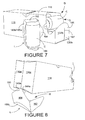
- the beveled panel 158b provides support to a user gripping the detachable portion (or trough L), shown in Figure 6 .
- a dispenser D is formed at one end of the blank which, in this embodiment, is provided by a plurality of panels formed from end wall panels 130b, 132b, opposed side wall panels 114, 118 and top wall panel 116.
- a trough L or detachable portion is removed from a corner portion of the side, end and opposite side wall panels to form the dispenser D shown in Figure 7 .
- the trough L there comprises a series of panels, panel 165a formed from the respective end wall panel 130b, panels 162,164, 166 formed from the side wall panel 114, the top wall panel 116, and the second side wall panel 118 respectively and panel 165b formed from end wall panel 132b.
- the panels forming the trough L are frangibly connected to the respective side, top and end wall panels by a weakened or frangible line of joinder 168.
- the frangible line 168 is shaped to define an opening O that is different in shape from the first embodiment. More specifically, the V- shaped portion of the frangible line 168 in the top wall panel 116 results in the dispenser opening O that improves the view of the upper tier can.
- This V-shaped portion of the frangible line 168 is also advantageous because it is arranged so as to overlie the second endmost article in the upper tier, not to overlie the space between the endmost and the adjacent inner articles. This arrangement prevents or at least mitigates undesired breakage or rupture of that portion of the tear line 168 in the top wall panel 116 during transportation, storage and/or handling of the carton.
- the portion of the frangible line 168 in the end wall panels 130b, 132b ( Figures 5 and 6 ) is curved to reach an elevation higher than the diameter of an article C. Stated differently, the highest point along the frangible line 168 within the end wall panels 130b, 132b is located at a distance greater from the base wall panel 112/120 than from the top wall panel 116.
- This arrangement provides the following three benefits: (1) a large-sized front graphic area, (2) a longer and stronger manufacturer's seam 187 ( Figure 7 ) between the end wall panels 130b, 132b that is less likely to break open during the removal of the trough L, and (3) a large-sized front stopper wall 185 ( Figure 7 ) that is capable of retaining the upper tier articles C within the carton upon and after removal of the trough L.
- the large-sized front stopper wall 185 is also of utility when a user desires to place the endmost article C (in the upper tier) back into the carton after it is once removed from the carton.
- the endmost article C (such as a can) may be placed with its side down in the space between the second endmost article and the stopper wall 185.
- the endmost article C may be placed with its bottom down on top of the stopper wall 185 while resting against the adjacent or second endmost article as shown in Figure 10 .
- the upper edge of the stopper wall 185 is arched, or upwardly convexly curved, with a suitable radius of curvature so as to snugly fit in the recessed bottom of the endmost can. Such an arrangement enhances the stability of the can on the stopper wall 185.
- each side wall panel 114,118 is shaped to extend across the adjacent end of the endmost article C in the lower tier so as to partially expose the opposite ends of the endmost can C as shown in Figure 7 , so that a user can easily grasp that can by the opposite ends. It is preferred that the intersection 161 ( Figures 4 and 5 ) of the frangible line 168 with either the fold line 134b or 136b is located at a distance greater from the base wall panel 112/120 than from the top wall panel 116 if not at the midpoint between the top and base wall panels 116 and 112/120. This arrangement helps to increase the rigidity of the stopper wall 185 while allowing a part of the endmost can C in the lower tier to be exposed to view.
- each finger punch-through arrangement S 1', S2' for grasping the trough L.
- a finger punch-through arrangement is struck from each side wall panel so that the trough L is displaced from the carton by using a cross-tearing motion.
- Each finger punch-through arrangement S 1', S2' is substantially the same as those shown in Figure 1 described above and are therefore not described in any further detail.
- the blank further comprises a suitable known handle HI to allow the user to carry the carton.
- first side wall panel 114 is folded inwardly along fold line 124 to lie flat on the top wall panel 116.
- Glue is applied to first base wall panel 112 as well as to support flaps 142a, 142b, and then second base wall panel 120 is folded inwardly along fold line 128 to lie flat on first base wall panel 112.
- first and second base wall panels 112,120 are glued together to form a composite base wall
- the support flaps 140a, 144a are glued together to form a composite support flap
- the support flaps 140b, 144b are glued together to form a composite support flap.
- the flat tubular carton is expanded into an open ended tubular form.
- Articles, for example cans C are loaded through one or both of the open ends of the carton and the end walls are formed to close the ends of the carton.
- the end wall is substantially the same, the rear end wall will hereinafter be described.
- support flaps 140a, 138a and 144a are folded inwardly along fold lines 142a, 139a and 146a respectively.
- the end wall panels 130a, 132a are followed inwardly along fold lines 134a and 136a respectively and they are secured together by glue or other suitable securing means.
- the support panels are also secured to the inner surface of the end wall panels 130a and 132a to provide additional support to the end wall.
- the opposing end wall i. e., the front end wall, is constructed in the same manner, and shall not be described in any further detail.
- the carton is in a completed and closed condition, shown in Figure 5 in which there is an erected carton.
- the trough L is integrally formed as an end portion of the carton to be removed to form the dispenser D ( Figure 7 ).
- the user grabs the trough L, by pushing his finger through either finger punch-through arrangement S1' or S2' to engage the edge of the trough L on the respective side wall and severs the trough L from the carton along the frangible line 168 using a cross tearing motion.
- Bevelled panel 158b can be used to support the user's thumb during the tearing motion, shown in Figure 6 .
- the end portion of the carton is exposed to provide a dispensing opening O for the articles as shown in Figure 7 .
- the articles C are accessible through the opening O.
- the trough is then used as a heel L to cause the carton to be inclined to encourage the remaining articles to the front end of the carton.
- the trough L is then engaged with the carton.
- this is achieved by inserting a protruding part 180 of the trough L into the gap between the composite support flap 140a/144a and the composite end wall panel 130a/132a as illustrated in Figure 8 .
- the composite base wall 112/120 of the carton abuts the edge of the composite panel 165b/165a ( Figures 7 and 10 ) of the trough L and the lower-rear corner of the carton abuts the inner surface of panel 164 thereby to define a heeled portion with the rear end of the carton raised relative the front end (having the dispenser).
- panels 162,166 are shaped to be juxtaposed with the side wall panels 118,114 of the carton thereby to provide additional lateral support to the heel L.
- the carton is in an inclined position shown in Figures 9 and 10 whereby articles C are accessible through the opening and are gravity-fed to the front end to improve ease of access to the articles contained within the carton.
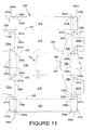
- FIG. 11 to 13 A third embodiment of the invention is shown in Figures 11 to 13 in which the blank is similar to that of the second embodiment and therefore like references have been used but replacing the numeral "1" with the numeral "2". Therefore, only the differences will be described in any greater detail.
- the trough T for forming the dispenser differs in that the ⁇ BR> ⁇ BR> finger punch-through arrangements S1 and S2 are replaced by a hand panel 287 (i. e., an alternative form of the protruding portion 180) hingedly connected to panel 264 along fold line 289.
- Hand panel 287 is frangibly connected to the top panel 216 along frangible line 268.
- the shape of the frangible line 268 differs from the second embodiment to provide a different shape of dispenser opening O and trough T.
- the trough T in this embodiment also provides an incline for the bottom wall of the carton.
- the rear support flaps 240a, 238a, 244a are hingedly connected to the end panels 230a, 232a by web panels 241a to improve the folding action of and construction of the end wall, described in more detail below.
- engagement flap 288 is provided to engage the heel in respect of the carton.
- Engagement flap 288 is hingedly connected to end wall panel 230a along fold line 286.
- the structure of the front end wall is identical to that of the rear end wall except that the front wall is free of the engagement flap 288.
- the base wall, side wall and top wall panels are constructed and secured together in the same manner as the second embodiment so that a flat collapsed tubular structure is formed.
- the front and rear end walls are formed in like manner.
- the main difference is that when the end wall panels 230a, 232a are folded outwardly along the fold lines 234a, 236a, the web panels 241a are folded inwardly and cause the support flaps 240a, 238a and 244a to be automatically folded inwardly along double fold lines 242a, 252a; 239a, 260a; 246a, 256a. End wall panels 230a, 232s are then folded inwardly and secured together.
- the front end wall is formed in the same manner; however, at the rear end of the carton, engagement flap 288 preferably is secured to support flap 240a, or support flaps 240a and 244a, by glue or other suitable means known in the art.
- the trough T is removed whereby the hand panel 287 is pushed inwardly by folding along fold line 289 and the user grips a portion of panel 264 and pulls the trough T to detach it from the remainder of the carton to reveal a dispenser opening O.
- the trough T is oriented in the same way as the second embodiment shown in Figure 8 , and it is engaged with the carton.
- the engagement flap 288 is separated or peeled from the support flap 240a so as to enable the hand panel 287 to be inserted into the gap between the composite end wall panel 230a/232a and the composite support flap 240a/244a to retain the heel.
- the shape of the trough T differs from the second embodiment in that the composite panel 265 is longer in vertical size so that the free edge of panel 265 in abutment with the base wall of the carton is positioned further forward along the carton thereby more effectively reinforcing the base wall.
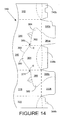
- a fourth embodiment is shown in Figures 14 , 15 and 16 and, again the blank shown in Figure 14 is substantially the same as the second embodiment shown in Figure 4 . Therefore, only part of the blank 310 is shown in Figure 14 and only the differences between the second and fourth embodiments will now be described.
- the tear line 368 includes two portions 369,371 in which the tear line is cranked so as to provide the protruding portion 380 of the panel 364 with a pair of opposed short side edges E (only one shown in Figures 15 and 16 ).
- the short side edges E are designed to engage the inside surfaces of the side wall panels 314,318 respectively when the protruding portion 380 of the panel 364 of the trough or heel L is inserted into the gap between the composite end wall panel 330a/332a and the composite support flap 340a/344a as shown in more detail in Figures 15 and 16 .
- This arrangement stabilizes the heel L with respect to the carton.
- the short side edges E are slightly divergent toward the support flap 338b.
- the maximum distance between the side edges E preferably, is generally equal to, or slightly greater than, the distance between the side wall panels 314 and 318 in the set up carton. This arrangement provides a wedging effect upon insertion of the protruding portion 380 into the gap so that the protruding portion 380 tightly fits in the gap to better stabilize the heel L.
- hinged connection should not be construed as necessarily referring to a single fold line only: indeed it is envisaged that hinged connection can be formed from one or more of one of the following, a score line, a frangible line or a fold line, without departing from the scope of invention.
- the size and shape of the panels and apertures may be adjusted to accommodate articles of differing size or shape, alternative top and base closure structures may be used.
- the carton may accommodate more than one article in different arrays.
Landscapes
- Engineering & Computer Science (AREA)
- Mechanical Engineering (AREA)
- Cartons (AREA)
- Control And Other Processes For Unpacking Of Materials (AREA)
- Packages (AREA)
Applications Claiming Priority (2)
| Application Number | Priority Date | Filing Date | Title |
|---|---|---|---|
| US10/397,646 US6902104B2 (en) | 2003-03-26 | 2003-03-26 | Carton with dispenser |
| EP04758163A EP1615840B1 (de) | 2003-03-26 | 2004-03-19 | Karton mit abgabevorrichtung |
Related Parent Applications (1)
| Application Number | Title | Priority Date | Filing Date |
|---|---|---|---|
| EP04758163A Division EP1615840B1 (de) | 2003-03-26 | 2004-03-19 | Karton mit abgabevorrichtung |
Publications (2)
| Publication Number | Publication Date |
|---|---|
| EP1988030A2 true EP1988030A2 (de) | 2008-11-05 |
| EP1988030A3 EP1988030A3 (de) | 2008-11-19 |
Family
ID=32989045
Family Applications (2)
| Application Number | Title | Priority Date | Filing Date |
|---|---|---|---|
| EP04758163A Expired - Lifetime EP1615840B1 (de) | 2003-03-26 | 2004-03-19 | Karton mit abgabevorrichtung |
| EP08162044A Withdrawn EP1988030A3 (de) | 2003-03-26 | 2004-03-19 | Karton mit Spender |
Family Applications Before (1)
| Application Number | Title | Priority Date | Filing Date |
|---|---|---|---|
| EP04758163A Expired - Lifetime EP1615840B1 (de) | 2003-03-26 | 2004-03-19 | Karton mit abgabevorrichtung |
Country Status (10)
| Country | Link |
|---|---|
| US (3) | US6902104B2 (de) |
| EP (2) | EP1615840B1 (de) |
| JP (1) | JP2006521255A (de) |
| AT (1) | ATE415358T1 (de) |
| AU (1) | AU2004226021A1 (de) |
| CA (1) | CA2519837A1 (de) |
| DE (1) | DE602004017979D1 (de) |
| MX (1) | MXPA05010309A (de) |
| RU (1) | RU2345940C2 (de) |
| WO (1) | WO2004087507A2 (de) |
Families Citing this family (100)
| Publication number | Priority date | Publication date | Assignee | Title |
|---|---|---|---|---|
| US6866186B2 (en) | 2002-10-16 | 2005-03-15 | Graphic Packaging International, Inc. | Carton with a dispenser in the top panel for dispensing pouches |
| US6918487B2 (en) | 2003-02-12 | 2005-07-19 | Graphic Packaging International, Inc. | Dispensing system for double stack carton |
| US6974072B2 (en) * | 2003-02-22 | 2005-12-13 | Graphic Packaging International, Inc. | Paperboard carton with a new type of dispenser |
| US7237674B2 (en) * | 2003-03-26 | 2007-07-03 | Meadwestvaco Packaging Systems, Llc | Carton with dispenser |
| US20060118606A1 (en) * | 2003-03-26 | 2006-06-08 | Holley John M Jr | Carton with dispenser |
| US6902104B2 (en) * | 2003-03-26 | 2005-06-07 | Meadwestvaco Packaging Systems, Llc | Carton with dispenser |
| US7147143B2 (en) * | 2003-08-01 | 2006-12-12 | Meadwestvaco Packaging Systems, Llc | Opening assist to dispensing carton |
| US7614497B2 (en) | 2003-10-15 | 2009-11-10 | Graphic Packaging International, Inc. | Display/vending carton |
| JP2007511438A (ja) * | 2003-11-19 | 2007-05-10 | ミードウエストヴェイコ・パッケージング・システムズ・エルエルシー | 物品の選択的な取り出し及び保持のための可撓ディスペンサーを画成する、2ステップ開口機能を有するカートン |
| US20050139501A1 (en) * | 2003-12-16 | 2005-06-30 | Lingamfelter C. B. | Container for providing easy access to beverage cans |
| US7401711B2 (en) * | 2004-02-10 | 2008-07-22 | Graphic Packaging International, Inc. | Carton having improved opening features |
| AU2005212419B2 (en) * | 2004-02-10 | 2008-11-20 | Graphic Packaging International, Inc. | Carton having opening and positioning features |
| US20050189405A1 (en) * | 2004-02-27 | 2005-09-01 | Jean-Manuel Gomes | Three by four can package dispensing carton |
| US7296731B2 (en) * | 2004-03-05 | 2007-11-20 | Meadwestvaco Packaging Systems, Llc | Carton with removable corner portion |
| US20050274638A1 (en) * | 2004-06-09 | 2005-12-15 | Georgia-Pacific Corporation | Combination shipping container and dispenser |
| WO2006031873A2 (en) * | 2004-09-14 | 2006-03-23 | The Coca-Cola Company | Carton with article opening |
| US7712653B2 (en) * | 2004-09-29 | 2010-05-11 | Graphic Packaging International, Inc. | Carton with dispenser having access features |
| WO2006042185A1 (en) * | 2004-10-11 | 2006-04-20 | Meadwestvaco Packaging Systems Llc | Carton with dispenser |
| WO2006050210A2 (en) * | 2004-10-29 | 2006-05-11 | Graphic Packaging International, Inc. | Carton having opening features |
| CA2586426A1 (en) * | 2004-11-12 | 2006-05-18 | Graphic Packaging International, Inc. | Cartons having tilt features |
| WO2006069166A1 (en) * | 2004-12-20 | 2006-06-29 | Meadwestvaco Packaging Systems, Llc | Carton with pressure sensitive opening device |
| US7614543B1 (en) * | 2005-01-07 | 2009-11-10 | The C. W. Zumbiel Company | Carton with gravity feed dispenser |
| US7422104B2 (en) * | 2005-02-22 | 2008-09-09 | Lava Group Packaging, Llc | Multi-pack packaging and dispenser |
| NZ560602A (en) * | 2005-02-28 | 2010-11-26 | Graphic Packaging Int Inc | Wrap-around carton with dispensing feature |
| US7617968B2 (en) * | 2005-03-30 | 2009-11-17 | Stephen C. Mertz | Can dispenser |
| WO2006125110A2 (en) * | 2005-05-19 | 2006-11-23 | Meadwestvaco Packaging Systems Llc | Carton with detachable portion |
| WO2007013976A2 (en) | 2005-07-22 | 2007-02-01 | Graphic Packaging International, Inc. | Carton with opening feature and blank |
| BRPI0614177A2 (pt) * | 2005-08-02 | 2011-03-15 | Graphic Packaging Int Inc | embalagem, método para disposição de uma embalagem em uma configuração de fornecimento, matriz para embalagem, embalagem com uma pluralidade de garrafas, e método para disposição de uma embalagem em uma configuração de fornecimento |
| US20070095697A1 (en) * | 2005-09-02 | 2007-05-03 | Jean-Michel Auclair | Carton with dispenser |
| CA2644238C (en) * | 2006-03-13 | 2011-01-25 | Graphic Packaging International, Inc. | Carton with dispenser |
| EP1999033B1 (de) | 2006-03-29 | 2012-09-26 | Graphic Packaging International, Inc. | Trägerpakete und verfahren zum aufrichten von trägerpaketen |
| US7478745B2 (en) * | 2006-03-31 | 2009-01-20 | International Paper Company | Container and blank having easy opening feature |
| US7568612B2 (en) * | 2006-04-04 | 2009-08-04 | Graphic Packaging International, Inc. | Carton with dispenser |
| DE602007005243D1 (de) * | 2006-05-01 | 2010-04-22 | Graphic Packaging Int Inc | Verstärkter karton |
| US20070261988A1 (en) * | 2006-05-12 | 2007-11-15 | Graham Packaging, Lp | Plastic case with simplified assembly and disassembly |
| US7475777B2 (en) * | 2006-05-31 | 2009-01-13 | Graphic Packaging International, Inc. | Carton with article retaining feature |
| WO2007150023A1 (en) * | 2006-06-23 | 2007-12-27 | Graphic Packaging International, Inc. | Carton with dispenser |
| ES2492920T3 (es) * | 2006-06-23 | 2014-09-10 | Graphic Packaging International, Inc. | Caja de cartón con distribuidor |
| CN101765545A (zh) * | 2007-07-27 | 2010-06-30 | 印刷包装国际公司 | 具有分配器、显示部件和/或拐角部件的纸盒 |
| US20090057384A1 (en) * | 2007-08-27 | 2009-03-05 | Angela Elizabeth Learn | Carton for dispensing products and method of using the same |
| US8733623B2 (en) * | 2007-12-24 | 2014-05-27 | Meadwestvaco Packaging Systems, Llc | Carrying handle for a carton |
| USD587997S1 (en) * | 2008-03-04 | 2009-03-10 | Cwip Nominee Trust | Container for dispensing garments |
| JP4702401B2 (ja) * | 2008-06-02 | 2011-06-15 | カシオ計算機株式会社 | カメラ、カメラ制御プログラム及びカメラ制御方法 |
| US20100044421A1 (en) * | 2008-08-21 | 2010-02-25 | Learn Angela E | Package for containers |
| AU2009282653A1 (en) * | 2008-08-22 | 2010-02-25 | Graphic Packaging International, Inc. | Carton with insert |
| US8317082B2 (en) | 2008-09-24 | 2012-11-27 | Graphic Packaging International, Inc. | Carton with locking sections |
| ES2425886T3 (es) | 2008-10-14 | 2013-10-17 | Graphic Packaging International, Inc. | Elemento portador con características de bloqueo |
| WO2010059693A2 (en) * | 2008-11-19 | 2010-05-27 | Graphic Packaging International, Inc. | Carton with curved panels and opening tab |
| US7931188B2 (en) * | 2009-01-09 | 2011-04-26 | Vito Marinelli | Combination pizza box and leveling device |
| BRPI1006157B1 (pt) | 2009-01-16 | 2019-05-28 | Graphic Packaging International, Llc | Caixa de acondicionamento para acondicionar uma pluralidade de artigos, combinação, de uma blanqueta cartonada e uma blanqueta de inserção para a formação de uma caixa de acondicionamento possuindo características reforçadas, e método de formar uma caixa de acondicionamento |
| ES2477222T3 (es) | 2009-03-17 | 2014-07-16 | Graphic Packaging International, Inc. | Caja de cartón con panel superior reforzado |
| CA2697419C (en) * | 2009-03-23 | 2014-03-18 | Kraft Foods Global Brands Llc | Apparatus pertaining to a single-piece blank and a corresponding clamshell-style carton |
| US8376214B2 (en) | 2009-07-14 | 2013-02-19 | Graphic Packaging International, Inc. | Carton with insert |
| US20110030321A1 (en) * | 2009-08-05 | 2011-02-10 | Brand Kirsten L | Carton With Dispensing Feature |
| EP2470439B1 (de) | 2009-08-28 | 2019-01-30 | Graphic Packaging International, LLC | Karton mit einsatz |
| EP2509468A4 (de) | 2009-12-11 | 2013-10-09 | Wrigley W M Jun Co | Ablage für eine anzeige |
| AU2011255597B2 (en) | 2010-05-19 | 2015-01-15 | Graphic Packaging International, Llc | Package for containers |
| CN102892685B (zh) | 2010-05-25 | 2014-09-17 | 印刷包装国际公司 | 具有插入件的纸箱 |
| EP2598411B1 (de) | 2010-07-30 | 2016-12-21 | Graphic Packaging International, Inc. | Träger für flaschen, zuschnitt und verfahren zu dessen herstellung |
| EP2616356B1 (de) | 2010-09-17 | 2016-03-16 | Graphic Packaging International, Inc. | Karton mit einsatz |
| CN103237740B (zh) | 2010-12-03 | 2015-01-07 | 印刷包装国际公司 | 用于容器的包装件 |
| WO2012145478A2 (en) | 2011-04-20 | 2012-10-26 | Graphic Packing International, Inc. | Carrier with locking features |
| CN103534177B (zh) | 2011-05-12 | 2015-05-13 | 印刷包装国际公司 | 具有保持结构的承载件 |
| MX339424B (es) | 2011-05-13 | 2016-05-25 | Graphic Packaging Int Inc | Empaque para recipientes. |
| BR112014002811B1 (pt) | 2011-08-05 | 2020-09-29 | Graphic Packaging International, Llc | Embalagem de acondicionamento compreendendo uma embalagem para acondicionamento e transporte que abriga pelo menos um recipiente, blanqueta para a formação de uma embalagem de acondicionamento e transporte para abrigar pelo menos parcialmente pelo menos um recipiente, e método para formar uma embalagem de acondicionamento |
| CN104245532B (zh) | 2012-04-27 | 2017-03-01 | 印刷包装国际公司 | 用于形成包装箱的组合件、包装箱和包装箱的形成方法 |
| EP2874905B1 (de) | 2012-07-17 | 2017-02-22 | Graphic Packaging International, Inc. | Karton mit einsatz |
| AU2013290750B2 (en) | 2012-07-17 | 2017-02-09 | Graphic Packaging International, Llc | Carton with article protection feature |
| AU2013299497B2 (en) | 2012-08-10 | 2016-10-27 | Graphic Packaging International, Llc | Carton with dispenser |
| WO2014055119A1 (en) | 2012-10-05 | 2014-04-10 | Graphic Packaging International, Inc. | Carton with dispensing feature |
| EP2996958B1 (de) | 2013-05-13 | 2018-01-17 | Graphic Packaging International, Inc. | Karton mit einsatz |
| WO2014186266A1 (en) | 2013-05-13 | 2014-11-20 | Graphic Packaging International, Inc. | Carton with article protection features |
| US10384846B2 (en) | 2013-05-24 | 2019-08-20 | Graphic Packaging International, Llc | Arrangement of containers in a carton |
| WO2014190267A1 (en) | 2013-05-24 | 2014-11-27 | Graphic Packaging International, Inc. | Carton for articles |
| EP3060493A1 (de) | 2013-10-25 | 2016-08-31 | Graphic Packaging International, Inc. | Karton mit rückhaltungsfunktionen |
| US9718246B2 (en) | 2013-12-10 | 2017-08-01 | Graphic Packaging International, Inc. | Carton with article protection features |
| AU2015222912B2 (en) | 2014-02-28 | 2019-10-03 | Graphic Packaging International, Llc | Carton with article protection features |
| US10322845B2 (en) | 2014-03-11 | 2019-06-18 | Graphic Packaging International, Llc | Carton with insert |
| ES2734410T3 (es) | 2014-03-11 | 2019-12-05 | Graphic Packaging Int Llc | Caja de cartón con un elemento de inserción |
| US10124947B2 (en) | 2014-06-23 | 2018-11-13 | Graphic Packaging International, Llc | Carton with dispensing features |
| US10549875B2 (en) | 2014-10-30 | 2020-02-04 | Graphic Packaging International, Llc | Carton with handle |
| CN107000859B (zh) | 2014-12-16 | 2019-11-05 | 印刷包装国际有限责任公司 | 用于物品的纸箱 |
| EP3245138B1 (de) | 2015-01-13 | 2019-07-03 | WestRock Packaging Systems, LLC | Karton und zuschnitt dafür |
| CA2981076C (en) | 2015-05-07 | 2019-04-30 | Graphic Packaging International, Inc. | Carton with handle |
| US10351291B2 (en) | 2015-05-29 | 2019-07-16 | Inteplast Group Corporation | Reusable produce containers and related methods |
| US9527622B2 (en) | 2015-05-29 | 2016-12-27 | Inteplast Group Ltd. | Reusable produce containers and related methods |
| WO2017023685A1 (en) | 2015-07-31 | 2017-02-09 | Graphic Packaging International, Inc. | Carton with dispenser |
| AU367153S (en) * | 2015-11-20 | 2016-02-15 | Visy R & D Pty Ltd | Blank for forming a container |
| CN109153482A (zh) * | 2016-05-06 | 2019-01-04 | 印刷包装国际有限责任公司 | 用于制品的纸箱 |
| US10220975B2 (en) | 2016-05-31 | 2019-03-05 | Inteplast Group Corporation | Column and cross stacking containers and related methods |
| USD812468S1 (en) * | 2016-07-01 | 2018-03-13 | Inteplast Group Corporation | Foldable container |
| US11214423B2 (en) | 2017-01-26 | 2022-01-04 | General Mills, Inc. | Carton with integrated handle assembly |
| RU177175U1 (ru) * | 2017-07-10 | 2018-02-12 | Владимир Антонович Ручкин | Двухуровневая картонная коробка |
| USD867900S1 (en) | 2018-03-01 | 2019-11-26 | Graphic Packaging International, Llc | Carrier |
| USD932900S1 (en) | 2018-12-21 | 2021-10-12 | Conopco, Inc. | Dispenser |
| USD904882S1 (en) * | 2019-06-17 | 2020-12-15 | Conopco, Inc. | Box |
| WO2021076751A1 (en) | 2019-10-17 | 2021-04-22 | Cargill, Incorporated | Display ready packaging |
| USD980069S1 (en) | 2020-07-14 | 2023-03-07 | Ball Corporation | Metallic dispensing lid |
| US12168551B2 (en) | 2021-03-01 | 2024-12-17 | Ball Corporation | Metal container and end closure with seal |
| US20250263222A1 (en) * | 2024-02-21 | 2025-08-21 | O&M Halyard, Inc. | Eyewear Dispensing Assembly |
Family Cites Families (43)
| Publication number | Priority date | Publication date | Assignee | Title |
|---|---|---|---|---|
| US230516A (en) * | 1880-07-27 | Stub cutter and slicer | ||
| US1497536A (en) * | 1921-11-21 | 1924-06-10 | Aaron M Billstein | Box |
| US1862685A (en) * | 1930-07-16 | 1932-06-14 | Kennett Frank | Shipping and display carton |
| US2294965A (en) * | 1940-02-02 | 1942-09-08 | Nat Biscuit Co | Shipping and display container |
| US2930516A (en) * | 1959-04-21 | 1960-03-29 | Gen Aniline & Film Corp | Paperboard container |
| US3189215A (en) * | 1962-10-30 | 1965-06-15 | Weyerhaeuser Co | Article carrier and package |
| US3228582A (en) * | 1963-03-12 | 1966-01-11 | Nat Lock Co | Shipping and storage carton |
| US3178242A (en) * | 1963-05-13 | 1965-04-13 | Anheuser Busch | One-piece dispensing carton for cylindrical objects |
| US3219181A (en) * | 1963-08-30 | 1965-11-23 | Novoratrag A G | Foldable box for packaging and displaying merchandise |
| US3229582A (en) * | 1964-01-31 | 1966-01-18 | Roland W Schlie | Mechanical pulse transformer |
| US3263861A (en) * | 1964-06-09 | 1966-08-02 | Lawless Bros Container Corp | Dispensing carton |
| US3265283A (en) * | 1964-12-11 | 1966-08-09 | Reynolds Metals Co | Shipping and dispensing carton |
| US3300115A (en) * | 1965-04-05 | 1967-01-24 | Boise Cascade Corp | Compartmented dispensing carton formed from a single blank |
| US3356279A (en) * | 1966-02-23 | 1967-12-05 | Reynolds Metals Co | Shipping and dispensing container means and blanks therefor |
| US3540581A (en) * | 1968-02-26 | 1970-11-17 | Lee Drechsler | Package construction for carrying horizontal superposed articles |
| US3750930A (en) * | 1972-06-28 | 1973-08-07 | Becton Dickinson Co | Carton |
| US3970215A (en) * | 1975-01-24 | 1976-07-20 | Hoerner Waldorf Corporation | Dispensing package for moistened tissues |
| US4030596A (en) * | 1976-05-24 | 1977-06-21 | Snyder Robert O | Cartons |
| US4113100A (en) * | 1977-01-27 | 1978-09-12 | Stone Container Corporation | Display carton |
| US4375258A (en) | 1981-04-13 | 1983-03-01 | Container Corporation Of America | Reusable enclosed carrier carton |
| US4396143A (en) * | 1981-08-31 | 1983-08-02 | Manville Service Corporation | Multiple article beverage package |
| US4416410A (en) | 1982-06-03 | 1983-11-22 | Herrmann Ronald S | Sandpaper roll dispenser |
| JPS5932570U (ja) * | 1982-08-27 | 1984-02-29 | マツダ株式会社 | パワ−ステアリング装置 |
| US4498581A (en) * | 1983-10-11 | 1985-02-12 | Champion International Corporation | Beverage can carton with opening panel |
| US4550834A (en) * | 1983-12-05 | 1985-11-05 | E. I. Du Pont De Nemours & Co. | Self-erecting end-load top-dispensing container |
| DE3612594A1 (de) | 1986-04-15 | 1987-10-29 | Focke & Co | Faltkarton mit schwenkbarer oeffnungslasche |
| JPH0330256Y2 (de) * | 1986-06-09 | 1991-06-26 | ||
| JP2527584Y2 (ja) * | 1991-04-19 | 1997-03-05 | レンゴー株式会社 | 飲料缶用包装箱 |
| US5289943A (en) * | 1992-04-20 | 1994-03-01 | Powell Philip M | Holder for dispensing cans from a multi-can carton |
| JPH079721U (ja) * | 1993-07-15 | 1995-02-10 | 東罐興業株式会社 | 包装箱 |
| US5375702A (en) * | 1993-08-11 | 1994-12-27 | Printech Inc. | Folding display box |
| ATE203480T1 (de) * | 1996-12-19 | 2001-08-15 | Gelderse Papiergroep N V | Verfahren zum verpacken eines stapels von blattförmigen gegenständen |
| US5878947A (en) * | 1997-06-19 | 1999-03-09 | Hoy; Richard W. | Multiple article beverage package |
| US6283293B1 (en) * | 2000-04-04 | 2001-09-04 | C. Brown Lingamfelter | Container for providing easy access to beverage cans |
| US6478219B1 (en) * | 2000-11-15 | 2002-11-12 | The Mead Corporation | Carton with article dispenser |
| AU2002230849B2 (en) * | 2000-12-12 | 2005-09-29 | Meadwestvaco Packaging Systems, Llc | Carton with dispenser |
| US6578736B2 (en) * | 2001-01-09 | 2003-06-17 | Riverwood International Corporation | Carton with an improved dispensing feature |
| US6484903B2 (en) * | 2001-01-09 | 2002-11-26 | Riverwood International Corporation | Carton with an improved dispensing feature in combination with a unique handle |
| US6929172B2 (en) * | 2002-06-21 | 2005-08-16 | Meadwestvaco Packaging Systems, Llc | Severable carton wall |
| US6974072B2 (en) * | 2003-02-22 | 2005-12-13 | Graphic Packaging International, Inc. | Paperboard carton with a new type of dispenser |
| US6902104B2 (en) * | 2003-03-26 | 2005-06-07 | Meadwestvaco Packaging Systems, Llc | Carton with dispenser |
| US7104435B2 (en) * | 2003-03-26 | 2006-09-12 | Meadwestvaco Packaging Systems Llc | Carton with dispenser |
| US7237674B2 (en) * | 2003-03-26 | 2007-07-03 | Meadwestvaco Packaging Systems, Llc | Carton with dispenser |
-
2003
- 2003-03-26 US US10/397,646 patent/US6902104B2/en not_active Expired - Fee Related
-
2004
- 2004-03-19 DE DE602004017979T patent/DE602004017979D1/de not_active Expired - Fee Related
- 2004-03-19 MX MXPA05010309A patent/MXPA05010309A/es active IP Right Grant
- 2004-03-19 WO PCT/US2004/008480 patent/WO2004087507A2/en not_active Ceased
- 2004-03-19 AU AU2004226021A patent/AU2004226021A1/en not_active Abandoned
- 2004-03-19 CA CA002519837A patent/CA2519837A1/en not_active Abandoned
- 2004-03-19 RU RU2005132932/12A patent/RU2345940C2/ru active
- 2004-03-19 AT AT04758163T patent/ATE415358T1/de not_active IP Right Cessation
- 2004-03-19 EP EP04758163A patent/EP1615840B1/de not_active Expired - Lifetime
- 2004-03-19 JP JP2006507381A patent/JP2006521255A/ja active Pending
- 2004-03-19 EP EP08162044A patent/EP1988030A3/de not_active Withdrawn
-
2005
- 2005-04-04 US US11/098,937 patent/US7207474B2/en not_active Expired - Lifetime
- 2005-12-02 US US11/293,671 patent/US7374076B2/en not_active Expired - Lifetime
Also Published As
| Publication number | Publication date |
|---|---|
| US20050224565A1 (en) | 2005-10-13 |
| ATE415358T1 (de) | 2008-12-15 |
| MXPA05010309A (es) | 2005-11-17 |
| US6902104B2 (en) | 2005-06-07 |
| US20060157546A1 (en) | 2006-07-20 |
| US7207474B2 (en) | 2007-04-24 |
| CA2519837A1 (en) | 2004-10-14 |
| WO2004087507A2 (en) | 2004-10-14 |
| US7374076B2 (en) | 2008-05-20 |
| EP1988030A3 (de) | 2008-11-19 |
| AU2004226021A1 (en) | 2004-10-14 |
| RU2345940C2 (ru) | 2009-02-10 |
| DE602004017979D1 (de) | 2009-01-08 |
| EP1615840B1 (de) | 2008-11-26 |
| WO2004087507A3 (en) | 2005-02-17 |
| RU2005132932A (ru) | 2006-02-27 |
| JP2006521255A (ja) | 2006-09-21 |
| EP1615840A2 (de) | 2006-01-18 |
| US20040188508A1 (en) | 2004-09-30 |
Similar Documents
| Publication | Publication Date | Title |
|---|---|---|
| EP1615840B1 (de) | Karton mit abgabevorrichtung | |
| EP1615841B1 (de) | Karton mit abgabevorrichtung | |
| EP1613537B1 (de) | Karton mit abgabevorrichtung | |
| US7296731B2 (en) | Carton with removable corner portion | |
| CA2502327C (en) | Carton with dispenser | |
| US7100798B2 (en) | Carton with an improved dispensing feature | |
| US7134551B2 (en) | Dispensing system for double stack carton | |
| WO2006042185A1 (en) | Carton with dispenser | |
| US20070023491A1 (en) | Carton with dispenser |
Legal Events
| Date | Code | Title | Description |
|---|---|---|---|
| PUAI | Public reference made under article 153(3) epc to a published international application that has entered the european phase |
Free format text: ORIGINAL CODE: 0009012 |
|
| PUAL | Search report despatched |
Free format text: ORIGINAL CODE: 0009013 |
|
| 17P | Request for examination filed |
Effective date: 20080807 |
|
| AC | Divisional application: reference to earlier application |
Ref document number: 1615840 Country of ref document: EP Kind code of ref document: P |
|
| AK | Designated contracting states |
Kind code of ref document: A2 Designated state(s): AT BE BG CH CY CZ DE DK EE ES FI FR GB GR HU IE IT LI LU MC NL PL PT RO SE SI SK TR |
|
| AX | Request for extension of the european patent |
Extension state: AL LT LV MK |
|
| AK | Designated contracting states |
Kind code of ref document: A3 Designated state(s): AT BE BG CH CY CZ DE DK EE ES FI FR GB GR HU IE IT LI LU MC NL PL PT RO SE SI SK TR |
|
| AX | Request for extension of the european patent |
Extension state: AL LT LV MK |
|
| STAA | Information on the status of an ep patent application or granted ep patent |
Free format text: STATUS: THE APPLICATION HAS BEEN WITHDRAWN |
|
| 18W | Application withdrawn |
Effective date: 20090122 |