EP1987897A1 - Device and method for transferring a coiled cable section - Google Patents
Device and method for transferring a coiled cable section Download PDFInfo
- Publication number
- EP1987897A1 EP1987897A1 EP08155335A EP08155335A EP1987897A1 EP 1987897 A1 EP1987897 A1 EP 1987897A1 EP 08155335 A EP08155335 A EP 08155335A EP 08155335 A EP08155335 A EP 08155335A EP 1987897 A1 EP1987897 A1 EP 1987897A1
- Authority
- EP
- European Patent Office
- Prior art keywords
- winding
- cable
- band
- roller
- grippers
- Prior art date
- Legal status (The legal status is an assumption and is not a legal conclusion. Google has not performed a legal analysis and makes no representation as to the accuracy of the status listed.)
- Granted
Links
Images


Classifications
-
- B—PERFORMING OPERATIONS; TRANSPORTING
- B65—CONVEYING; PACKING; STORING; HANDLING THIN OR FILAMENTARY MATERIAL
- B65H—HANDLING THIN OR FILAMENTARY MATERIAL, e.g. SHEETS, WEBS, CABLES
- B65H54/00—Winding, coiling, or depositing filamentary material
- B65H54/56—Winding of hanks or skeins
- B65H54/58—Swifts or reels adapted solely for the formation of hanks or skeins
-
- B—PERFORMING OPERATIONS; TRANSPORTING
- B21—MECHANICAL METAL-WORKING WITHOUT ESSENTIALLY REMOVING MATERIAL; PUNCHING METAL
- B21C—MANUFACTURE OF METAL SHEETS, WIRE, RODS, TUBES OR PROFILES, OTHERWISE THAN BY ROLLING; AUXILIARY OPERATIONS USED IN CONNECTION WITH METAL-WORKING WITHOUT ESSENTIALLY REMOVING MATERIAL
- B21C47/00—Winding-up, coiling or winding-off metal wire, metal band or other flexible metal material characterised by features relevant to metal processing only
- B21C47/24—Transferring coils to or from winding apparatus or to or from operative position therein; Preventing uncoiling during transfer
-
- Y—GENERAL TAGGING OF NEW TECHNOLOGICAL DEVELOPMENTS; GENERAL TAGGING OF CROSS-SECTIONAL TECHNOLOGIES SPANNING OVER SEVERAL SECTIONS OF THE IPC; TECHNICAL SUBJECTS COVERED BY FORMER USPC CROSS-REFERENCE ART COLLECTIONS [XRACs] AND DIGESTS
- Y10—TECHNICAL SUBJECTS COVERED BY FORMER USPC
- Y10T—TECHNICAL SUBJECTS COVERED BY FORMER US CLASSIFICATION
- Y10T24/00—Buckles, buttons, clasps, etc.
- Y10T24/14—Bale and package ties, hose clamps
Definitions
- the invention relates to a device and a method for the adoption of a winder and for further transport to a storage of a wound into a winding cable section according to the definition of the independent claims.
- the publication DE 42 35 007 A1 discloses a winding device for cable sections, in which the inner walls of a drum serve as contact surfaces for the formation of the coil and thus predetermine the outer diameter of the roll.
- the drum remains at rest during the insertion of the cable and is opened after reaching the cable length and setting of the coil. After the transfer of the two cable ends of the roll to transfer gripper subsequent cable finishing, such as crimping and / or grommets put on, feasible.
- disadvantages are also to be mentioned, such as, for example, uncontrollable bending radii during insertion and compression of the various winding layers for setting. Whether the individual wraps always rest against the wall is uncertain. Minimum bending radii at the entrance and exit of the cable in or out of the drum are also not given.
- the font WO 03/018456 A1 discloses a winding device for a cable with a rotating winding mandrel, are arranged in the hanging and spreadable winding arms. Depending on the cable section, the arms are more or less spread so that after reaching the cable length approximately both cable ends are the same length. For the processing of the cable ends, the winding is taken over after setting of transfer grippers.
- the invention aims to remedy this situation.
- the invention as characterized in the main claims, solves the problem of providing a device and a method for producing long cable sections without prolonging the entire processing time.
- the inventive device is particularly suitable for cable processing machines with swivel arms.
- the inventive device can also be used in transfer machines with linearly movable transport units, if additional grippers and transfer devices for handling the cable ends and the cable winding are provided.
- the winder is arranged between a separating / detaching unit and a second pivoting arm.
- the winding of the cable section is effected by means of a winding plate, which is rotatable by means of a controlled motor in response to a likewise motor-driven belt drive, the belt drive is the cable feed and the length measurement of the advanced cable.
- This arrangement is particularly advantageous for elastic cables.
- the leading cable end of the cable to be wound is by means of Edited processing stations and after processing by means of a first swivel arm swung back to the separation / Abisolieraji and advanced with the tape drive a short length, the winder can grab the leading cable end.
- the tape drive advances the cable to the desired length of the cable section and the winder winds the advanced cable simultaneously to a reel.
- a linearly displaceable depositing unit grips the winding.
- the winder disc relaxes its clamping fingers pneumatically and moves pneumatically to the rear. Shims act as scrapers prevent pulling the coil to the rear.
- the laying unit moves back with the winding so that the trailing end of the cable can be separated and stripped and, if necessary, machined, with a second pivot arm feeding the trailing end of the cable to processing stations.
- Grippers of the depositing unit hold the winding and the depositing unit moves to about below the pivot point of the second pivot arm and the trailing end of the cable can, if necessary, be pulled out of the winding for the processing of its end by means of the second pivot arm.
- the depositing unit moves further in the cable feed direction for storage.
- the winding can be provided with a joinery.
- the winding may be provided with the joinery during processing of the trailing cable end or during processing of the leading cable end of the next cable section.
- the set winding can then be dispensed into containers, on conveyor belts or other receiving means, such as mandrels.
- the advantages achieved by the invention are essentially to be seen in the fact that the Abbindvorgang takes place on the winding time parallel to the processing operation on the cable section.
- the total processing time for the cable section also called machine cycle time, not extended.
- the total processing time remains the same with or without joinery.
- the time for making the coil is comparable to the time taken to deposit a stretched cable section in a conventional cable processing machine.
- the winder and the depositing unit are not connected as a separate device to the cable processing machine but form an integral unit of the cable processing machine.
- the manufactured and to be processed cable section is cut from the cable stock, processed at the leading end of the cable, wound up, possibly processed at the trailing cable end and handed over as a winding with Abbund the tray without manual intervention is necessary.
- the cable processing machine builds short in spite of long cable sections compared to a conventional cable processing machine.
- the length of the cable processing machine is not determined by the length of the cable section.
- the cable section is cut to length from a cable supply and processed at the cable ends, wherein a winder is provided which supports the cable section Cable section forms into a winding with at least one turn and provides a laying unit with a Abbind recognized the winding with a Abbund.
- Fig. 1 shows a cable section 1, which is formed with a plurality of turns 3 to a winding 2, wherein the turns 3 are held together by means of a 4 Abb.
- the leading cable end 5 is processed, for example, a crimp contact 6 is possibly struck with a grommet.
- the leading cable end 5 can also only be stripped or not processed.
- the trailing cable end 7 is processed, for example, a crimp contact 8 is possibly struck with a grommet.
- the trailing cable end 7 can only be stripped or not processed.
- Fig. 2 shows a cable processing machine 10 in plan and Fig. 3 the cable processing machine 10 in three-dimensional representation.
- a cable feed device consisting of a belt drive 11 and a length measuring device 12.
- the belt drive 11 leads a cable 13 to a first pivot arm 14 with a first gripper 15.
- the tape drive 11 advances the cable 13 and the length measuring device 12 measures the extended cable length, the extended cable length corresponds to the produced and to be processed at the ends cable section.
- the cable supply such as a cable drum or a cable coil.
- the first pivot arm 14 can be placed in a symbolized by an arrow P1 pivoting movement and / or in a symbolized by an arrow P2 linear motion.
- the first pivot arm 14 serves as a feeding device by means of rotary motion P1 and linear movement P2 side of the cable longitudinal axis KL arranged processing stations 16 (for example, crimping presses and / or Tüllenbe Anlagener) with leading cable ends. 5
- the leading cable end 5 brings the first pivot arm 14 by means of gripper 15, the leading cable end 5 back into the cable longitudinal axis KL. Then the cable 13 is advanced by means of belt drive 11 until a winder 17 can reach the leading cable end 5. Thereafter, the tape drive 11 advances the predetermined cable section 1 measured by the length measuring device 12, and the winder 17 synchronized with the tape drive 11 winds the advanced cable section simultaneously to form a reel 2 Fig. 1 on. After the production of the coil 2, the cable section 1 is separated from the cable 13 by means of a separating / Abisolierü with separation / Stripping 18 and / or stripped. The leading cable end of the next cable section is taken by the first pivot arm 14 by means of grippers 15 and fed to the processing stations 16 for processing.
- the trailing cable end 7 of the wound Cable section 1 is taken by a second pivot arm 19 by means of second gripper 20 and placed in a symbolized by an arrow P3 pivoting movement and / or in a symbolized by an arrow P4 linear movement, the trailing cable end 7 laterally of the cable longitudinal axis KL arranged processing stations 21 (for example crimping presses and / or Tüllenbe collaborativeer) is supplied.
- the winding 2 is taken over by winding grippers 22 of a laying unit 23. Thereafter, the depositing unit 23 moves in the direction of cable feed in the direction of a tray 24 until the depositing unit 23 comes to rest approximately below the swivel arm drive 25 of the second swivel arm 19.
- a belt station 26 Before processing the trailing cable end 7, a belt station 26 provides a belt section for the production of the truss 4. The band section is taken over by a setting device 27 of the laying unit 23.
- the trailing cable end 7 of the second arm 19 brings by means of gripper 20, the trailing end of the cable 7 back approximately in the cable longitudinal axis KL and the depositing unit 23 is moved with the winding 2 in the direction of tray 24.
- the joining 4 is produced by means of the binding device 27.
- the winding 2 with Abbund 4 is sorted according to good / bad criteria placed in one or the other container 31 of the tray 24.
- a belt drive 28 moves the laying unit 23 by means of belts 85 along a linear guide 29 arranged on a machine frame 30.
- Fig. 3 the directional arrows x, y and z are entered.
- the cable 13 is advanced by means of the belt drive 11 in the x direction, or the cable longitudinal axis KL is in the x direction.
- the laying unit 23 moves in the x-direction and places the finished roll 2 in the z-direction in the corresponding container 31.
- the winder 17 is for stripping the roll 2 as in Fig. 6 shown movable in the y-direction.
- Fig. 4 shows the winder 17, which forms the cable section 1 to a winding 2.
- a rotatable Wicklerteller 32 support fingers 33 and clamping fingers 34 are circular, peripherally arranged. Support fingers 33 and clamping fingers 34 carry the turns 3 of the coil second Fig. 7 shows details of the fingers 33,34.
- the Wicklerteller 32 lies in the plane spanned by the axes x and z plane and rotates about a horizontal axis of rotation 86 which is parallel to the y-axis. After processing the leading cable end 5 of the tape drive 11 pushes the cable 13 before.
- the roller 35 and a counter-finger 42 are additionally set into a rotational movement P7 by means of a drive unit 43 into a linear movement P6 and the counter-finger 42.
- the roller 35 displaces a guide finger 36 into a rotational movement P5 about a fixed axis 48, wherein the guide finger 36 moves toward the counter-finger 42 and deflects the cable 13 in the direction of an open winder gripper 37 during advancement.
- Guide fingers 36 and counter-fingers 42 also serve as guide aids for laterally guiding the cable 13.
- the winder gripper 37 is arranged on the winder disk 32 within the circle formed by the fingers 33, 34.
- Roller 35, guide finger 36, counter-finger 42 and the Linear movement P6 generating drive unit 43 form the opposite the Wicklerteller 32 fixed cable guide 38.
- the length measuring device 12 measures the extended cable length and the controller stops the belt drive 11 as soon as the cable gripper 37 necessary cable length is reached. Then the winder gripper 37 encompassing the cable end is closed.
- a winder drive 39 drives the Wicklerteller 32, wherein the winder drive 39 and the tape drive 11 are synchronized during manufacture of the coil 2, which advances the tape drive 11 to cable is wound from the Wickler plate 32 at the same time, the turns 3 of the resulting roll 2 on the Fingers 33,34 rest.
- the winding 2 is taken by the winding grippers 22 of the depositing unit 23 and the Wicklerteller 32 moves in the y direction by means of a cylinder 41, wherein a between the fingers 33,34 cross, relative to the Wicklerteller 32 fixedly arranged scraper 40 the winding. 2 from the fingers 33,34 pushes. Details are in Fig. 6 and Fig. 7 shown.
- Fig. 5 shows the back of the winder 17 and Fig. 6
- a motor pulley of the winder drive 39 drives a toothed belt 45 which drives a Wicklerpulley 46 and thus the Wicklerteller 32.
- the Wicklerteller 32 is movable together with the winder drive 39 along linear guides 47 in the y direction by means of cylinder 41 for the purpose of stripping the roll 2 of the fingers 33,34, the winding 2 is present on the fixed scraper 40 and so on the fingers 33, 34 is pushed.
- 49 designates an air connection, via which compressed air can be supplied to pneumatic units (winder gripper 37, clamping finger 34) of the winder disk 32.
- the motor pulley 44 is connected to the winder drive 39 by means of a coupling 50.
- Fig. 7 shows details of the winder 17 in particular arranged on the Wicklerteller 32 pneumatic units such as Wicklergreifer 37 and clamping fingers 34.
- the support fingers 33 carry the turns 3 of the coil 2.
- the clamping fingers 34 carry and hold the turns 3 of the coil 2.
- Each clamping finger 34 points at the free End of a nose 51, which restrain the winding 2 during the winding process.
- the clamping finger 34 is rotatable about an axis 53 by means of a pneumatic drive 52. In the position shown, the winding 2 can be stripped off by the fingers 33, 34 by means of scrapers 40.
- the pneumatic actuator 52 actuated by means of a cylinder 54 about an axis 73 rotatable lever 55 which rotates the clamping finger 34 by means of engaging in slots 56 bolt 57 about the axis 53 until the clamping finger 34 has the same position as the support fingers 33. In this position, the Wicklerteller 32 ready for the winding process.
- Fig. 7 shows the Wicklergreifer 37 for holding the leading cable end 5.
- the two gripper halves 58 shown in the closed position are pneumatically rotatable about an axis 59 and open and engage around by means of fingers 60 the cable end.
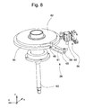
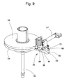
- Fig. 8 to Fig. 10 show a belt station 26 in which an adhesive tape 61 is prepared with one-side applied adhesive layer to a necessary for the Abbund 4 length.
- a tape supply 62 is located on a z-direction by means of cylinder 63 vertically adjustable belt plate 64, which is for the first time, manual threading of the adhesive tape 61 for better accessibility in the upper layer.
- a finger 65 with two finger pins 66 is arranged on the belt plate 64.
- the adhesive tape 61 is on the adhesive-less or dry side manually peeled off the plate-like finger bolt 66 and the beginning of the tape glued on the side with the adhesive layer on the finger plate remote from the blade 66.
- the manual threading is completed and the belt plate 64 is lowered and pivoted by means of cylinder 67 until the adhesive tape 61 as in Fig. 9 shown in line is with an extendable deflecting pin 68 and a band gripper 69 with knife 70. Thereafter, the band gripper 69 is closed and the adhesive tape 61 severed by means of knife 70. As in Fig. 10 shown the belt plate 64 is pivoted back into the starting position. The tape residue sticking to the remote finger pin 66 is manually removed. A linearly actuatable by means of pneumatic linear unit 71 in the y-direction tape take-off gripper 72 is then moved open between deflecting pin 68 and belt gripper 69.
- the tape take-off gripper 72 is closed and the tape gripper 69 is opened.
- the linear unit 71 now moves the tape take-off gripper 72 back and with it the adhesive tape 61 is pulled along from the tape supply 62 by the length as it is necessary for the production of 4 Abb.
- a tape with comparable properties can be used.
- Fig. 11 and FIG. 12 show the laying unit 23 in the acquisition of the adhesive tape 61 prepared by the tape station 26.
- Fig. 11 shows the depositing unit 23 together with parts of the belt station 26 from below, for the sake of clarity, only the upper winding gripper 22 is made visible, the lower winding gripper is in Fig. 11 not shown.
- the winding gripper 22 are not yet closed, the winding 2 is in Fig. 11 still held by the fingers 33,34 of the Wicklertellers 32.
- the drawn from the tape take-off gripper 72 from the tape supply 62 adhesive tape 61 is held by two each consisting of a rotatable roller arm 74 and a fixed pressure arm 75 roller grippers 76, wherein the tape take-off gripper 72 has already been opened.
- the roller grippers 76 are part of the binding device 27.
- the band gripper 69 When the band gripper 69 is closed, the adhesive tape 61 running in the y direction is severed by means of the knife 70 at the point 77 marked with dots.
- the cable storage-side end of the adhesive tape 61 is held by the band gripper 69.
- Fig. 12 Shown is the depositing unit 23 and the binding device 27 ready for the movement in the x direction to the tray 24 and on the way to the tray 24 for the production of the composite 4.
- the winding 2 has been taken over by the winding grippers 22 from the winder 17 and is of these recorded.
- the section of the adhesive tape 61 is held in place by means of the roller grippers 76 and is ready for the setting process.
- Fig. 13 and Fig. 14 show the Abbind worn 27 during Abbindvorgang.
- the winding grippers 22 have been shown not visible because of the better overview.
- the roller arm 74 of the roller gripper 76 can perform the rotational movement P8 and is rotatable by means of a pneumatic rotary unit 78.
- a roller 79 of the roller arm 74 presses the adhesive tape 61 against the pressure arm 75, wherein the non-adhesive side of the adhesive tape 61 on the pressure arm 75 and the adhesive layer of the adhesive tape 61 on the roller 79 is located.
- Reel grab 76 and rotary unit 78 are movable by means of a pneumatic linear unit 80 in the y-direction, wherein the two roller claws 76 are movable against each other or apart.
- the two pneumatic linear units 80 are in turn movable in the x-direction by means of a pneumatic, consisting of push rods 82 and cylinder 83 linear unit 81.
- a pneumatic linear unit 80 is in turn movable in the x-direction by means of a pneumatic, consisting of push rods 82 and cylinder 83 linear unit 81.
- the roller grippers 76 have been moved in the x-direction against the cable feed direction to the winder 17, the adhesive layer of the adhesive tape 61 coming to rest on the winding 2. Due to the relative movement of the roller gripper 76 relative to the winding 2, the in Fig.
Abstract
Description
Die Erfindung betrifft eine Einrichtung und ein Verfahren zur Übernahme von einem Wickler und zum Weitertransport zu einer Ablage eines zu einem Wickel geformten Kabelabschnittes gemäss der Definition der unabhängigen Patentansprüche.The invention relates to a device and a method for the adoption of a winder and for further transport to a storage of a wound into a winding cable section according to the definition of the independent claims.
Die Offenlegungsschrift
Aus der Patentschrift
Die Schrift
Die Handhabung langer Kabelabschnitte (ab beispielsweise 7 m Kabellänge) ist bei vielen Typen von Kabelbearbeitungsmaschinen schwierig. Bei Schwenkmaschinen mit Schwenkarmen muss die Kabelablage so lang wie der Kabelabschnitt sein. Bei Transfermaschinen mit auf einer Geraden verfahrbaren Transfereinheiten liegen beim Transport mehrere schlaufenförmige Kabel aufeinander, was bei einem schnellen Transport mittels der Transfereinheit relativ hohe Kabelzugkräfte bewirken kann, weil das Kabel nur an den Enden gehalten wird.The handling of long cable sections (for example, 7 m cable length) is difficult in many types of cable processing machines. For swivel machines with swivel arms, the cable tray must be as long as the cable section. In transfer machines with transfer units that can be moved on a straight line, a plurality of loop-shaped cables lie on top of each other during transport, which can cause relatively high cable pulling forces during rapid transport by means of the transfer unit because the cable is held only at the ends.
In den oben genannten Schriften sind Lösungsansätze für Transfermaschinen aufgezeigt worden. Separate, der Kabelbearbeitungsmaschine nachgeschaltete Wickelvorrichtungen konnten sich nicht durchsetzen, weil mit den seriellen Bearbeitungsprozessen die Taktzeit bzw. die gesamte Bearbeitungszeit für einen aufgewickelten Kabelabschnitt entsprechend lang war.In the above-mentioned writings are solutions for Transfer machines have been shown. Separate, the cable processing machine downstream winders could not prevail, because with the serial machining processes, the cycle time or the total processing time for a coiled cable section was correspondingly long.
Hier will die Erfindung Abhilfe schaffen. Die Erfindung, wie sie in den Hauptansprüchen gekennzeichnet ist, löst die Aufgabe, eine Einrichtung und ein Verfahren zur Herstellung von langen Kabelabschnitten zu schaffen ohne die gesamte Bearbeitungszeit zu verlängern.The invention aims to remedy this situation. The invention, as characterized in the main claims, solves the problem of providing a device and a method for producing long cable sections without prolonging the entire processing time.
Vorteilhafte Weiterbildungen der Erfindung sind in den abhängigen Patentansprüchen angegeben.Advantageous developments of the invention are specified in the dependent claims.
Die erfindungsgemässe Einrichtung eignet sich besonders für Kabelbearbeitungsmaschinen mit Schwenkarmen. Die erfindungsgemässe Einrichtung kann aber auch bei Transfermaschinen mit linear verfahrbaren Transporteinheiten verwendet werden, falls zusätzliche Greifer und Übergabevorrichtungen für die Handhabung der Kabelenden und des Kabelwickels vorgesehen sind.The inventive device is particularly suitable for cable processing machines with swivel arms. The inventive device can also be used in transfer machines with linearly movable transport units, if additional grippers and transfer devices for handling the cable ends and the cable winding are provided.
Im nachfolgend gezeigten Ausführungsbeispiel einer Kabelbearbeitungsmaschine mit Schwenkarmen ist der Wickler zwischen einer Trenn-/Abisoliereinheit und einem zweiten Schwenkarm angeordnet. Die Aufwicklung des Kabelabschnittes erfolgt mittels eines Wickeltellers, der mittels geregeltem Motor in Abhängigkeit eines ebenfalls motorisch geregelten Bandantriebes drehbar ist, wobei der Bandantrieb dem Kabelvorschub und der Längenmessung des vorgeschobenen Kabels dient. Diese Anordnung ist besonders vorteilhaft für elastische Kabel. Das voreilende Kabelende des aufzuwickelnden Kabels wird mittels Bearbeitungsstationen bearbeitet und nach der Bearbeitung mittels eines ersten Schwenkarmes wieder zur Trenn-/Abisoliereinheit zurückgeschwenkt und mit dem Bandantrieb eine kurze Länge vorgeschoben, wobei der Wickler das voreilende Kabelende greifen kann. Dann schiebt der Bandantrieb das Kabel um die gewünschte Länge des Kabelabschnittes vor und der Wickler wickelt das vorgeschobene Kabel gleichzeitig zu einem Wickel. Nach dem Wickelvorgang ergreift eine linear verfahrbare Ablegeinheit den Wickel. Dabei entspannt der Wicklerteller seine Spannfinger pneumatisch und fährt pneumatisch nach hinten. Formbleche wirken als Abstreifer verhindern das Mitziehen des Wickels nach hinten. Dann bewegt sich die Ablegeinheit mit dem Wickel zurück, damit das nacheilende Kabelende getrennt und abisoliert und falls nötig bearbeitet werden kann, wobei ein zweiter Schwenkarm das nacheilende Kabelende Bearbeitungsstationen zuführt. Greifer der Ablegeinheit halten den Wickel und die Ablegeinheit bewegt sich bis etwa unter den Drehpunkt des zweiten Schwenkarmes und das nacheilende Kabelende kann, falls nötig, für die Bearbeitung seines Endes mittels des zweiten Schwenkarmes noch aus dem Wickel ausgezogen werden. Nach der Bearbeitung des nacheilenden Kabelendes bewegt sich die Ablegeinheit weiter in Kabelvorschubrichtung zur Ablage. Während der Bearbeitung des nacheilenden Kabelendes und auf der Fahrt zur Ablage kann der Wickel mit einem Abbund versehen werden. Der Wickel kann während der Bearbeitung des nacheilenden Kabelendes oder während der Bearbeitung des voreilenden Kabelendes des nächsten Kabelabschnittes mit dem Abbund versehen werden. Der abgebundene Wickel kann danach in Behälter, auf Transportbänder oder sonstige Aufnahmemittel, beispielsweise Dorne abgegeben werden.In the exemplary embodiment of a cable processing machine with pivoting arms shown below, the winder is arranged between a separating / detaching unit and a second pivoting arm. The winding of the cable section is effected by means of a winding plate, which is rotatable by means of a controlled motor in response to a likewise motor-driven belt drive, the belt drive is the cable feed and the length measurement of the advanced cable. This arrangement is particularly advantageous for elastic cables. The leading cable end of the cable to be wound is by means of Edited processing stations and after processing by means of a first swivel arm swung back to the separation / Abisoliereinheit and advanced with the tape drive a short length, the winder can grab the leading cable end. Then, the tape drive advances the cable to the desired length of the cable section and the winder winds the advanced cable simultaneously to a reel. After the winding process, a linearly displaceable depositing unit grips the winding. The winder disc relaxes its clamping fingers pneumatically and moves pneumatically to the rear. Shims act as scrapers prevent pulling the coil to the rear. Then, the laying unit moves back with the winding so that the trailing end of the cable can be separated and stripped and, if necessary, machined, with a second pivot arm feeding the trailing end of the cable to processing stations. Grippers of the depositing unit hold the winding and the depositing unit moves to about below the pivot point of the second pivot arm and the trailing end of the cable can, if necessary, be pulled out of the winding for the processing of its end by means of the second pivot arm. After processing the trailing cable end, the depositing unit moves further in the cable feed direction for storage. During processing of the trailing end of the cable and on the way to the storage, the winding can be provided with a joinery. The winding may be provided with the joinery during processing of the trailing cable end or during processing of the leading cable end of the next cable section. The set winding can then be dispensed into containers, on conveyor belts or other receiving means, such as mandrels.
Die durch die Erfindung erreichten Vorteile sind im wesentlichen darin zu sehen, dass der Abbindvorgang am Wickel zeitlich parallel zum Bearbeitungsvorgang am Kabelabschnitt erfolgt. Damit wird die gesamte Bearbeitungzeit für den Kabelabschnitt, auch Maschinenzykluszeit genannt, nicht verlängert. Die gesamte Bearbeitungszeit bleibt dieselbe mit oder ohne Abbund. Die Zeit für die Herstellung des Wickels ist vergleichbar mit der Zeit für die Ablage eines gestreckten Kabelabschnittes bei einer herkömmlichen Kabelbearbeitungsmaschine.The advantages achieved by the invention are essentially to be seen in the fact that the Abbindvorgang takes place on the winding time parallel to the processing operation on the cable section. Thus, the total processing time for the cable section, also called machine cycle time, not extended. The total processing time remains the same with or without joinery. The time for making the coil is comparable to the time taken to deposit a stretched cable section in a conventional cable processing machine.
Mechanisch ist der Wickler und die Ablegeinheit nicht als separate Einrichtung zur Kabelbearbeitungsmaschine geschaltet, sondern bildet eine integrale Einheit der Kabelbearbeitungsmaschine. Der herzustellende und zu bearbeitende Kabelabschnitt wird ab dem Kabelvorrat abgelängt, am voreilenden Kabelende bearbeitet, aufgewickelt, allenfalls am nacheilenden Kabelende bearbeitet und als Wickel mit Abbund der Ablage übergeben ohne dass ein manueller Eingriff notwendig ist.Mechanically, the winder and the depositing unit are not connected as a separate device to the cable processing machine but form an integral unit of the cable processing machine. The manufactured and to be processed cable section is cut from the cable stock, processed at the leading end of the cable, wound up, possibly processed at the trailing cable end and handed over as a winding with Abbund the tray without manual intervention is necessary.
Weiter vorteilhaft ist, dass die Kabelbearbeitungsmaschine trotz langer Kabelabschnitte gegenüber einer herkömmlichen Kabelbearbeitungsmaschine kurz baut. Die Länge der Kabelbearbeitungsmaschine wird nicht durch die Länge des Kabelabschnittes bestimmt.It is also advantageous that the cable processing machine builds short in spite of long cable sections compared to a conventional cable processing machine. The length of the cable processing machine is not determined by the length of the cable section.
Bei der erfindungsgemässen Kabelbearbeitungsmaschine und dem erfindungsgemässen Verfahren zur Herstellung und Bearbeitung eines Kabelabschnittes wird der Kabelabschnitt ab einem Kabelvorrat abgelängt und an den Kabelenden bearbeitet, wobei ein Wickler vorgesehen ist, der den Kabelabschnitt zu einem Wickel mit mindestens einer Windung formt und eine Ablegeinheit mit einer Abbindeinrichtung den Wickel mit einem Abbund versieht.In the cable processing machine according to the invention and the method according to the invention for producing and processing a cable section, the cable section is cut to length from a cable supply and processed at the cable ends, wherein a winder is provided which supports the cable section Cable section forms into a winding with at least one turn and provides a laying unit with a Abbindeinrichtung the winding with a Abbund.
Anhand der beiliegenden Figuren wird die vorliegende Erfindung näher erläutert.Reference to the accompanying figures, the present invention will be explained in more detail.
Es zeigen:
-
Fig. 1
einen zu einem Wickel geformten Kabelabschnitt, -
Fig. 2
eine Kabelbearbeitungsmaschine im Grundriss, -
Fig. 3
eine Kabelbearbeitungsmaschine in dreidimensionaler Darstellung, -
Fig. 4
einen Wickler, der den Kabelabschnitt zu einem Wickel formt, -
Fig. 5
den Wickler von der Rückseite her gesehen, -
Fig. 6
Linearführungen eines Wicklertellers, -
Fig. 7
Einzelheiten des Wicklers, -
Fig. 8 bis Fig. 10
eine Bandstation zur Vorbereitung eines Klebbandes, -
Fig. 11 undFig 12
eine Ablegeinheit bei der Übernahme des Klebbandes, -
Fig. 13 undFig. 14
eine Abbindeinrichtung beim Abbindvorgang.
-
Fig. 1
a cable section formed into a winding, -
Fig. 2
a cable processing machine in plan, -
Fig. 3
a cable processing machine in three-dimensional representation, -
Fig. 4
a winder that forms the cable section into a roll, -
Fig. 5
the winder seen from the back, -
Fig. 6
Linear guides of a winder plate, -
Fig. 7
Details of the winder, -
Fig. 8 to Fig. 10
a belt station for preparing an adhesive tape, -
Fig. 11 andFIG. 12
a depositing unit when taking over the adhesive tape, -
Fig. 13 andFig. 14
a setting device during Abbindvorgang.
Am Eingang der Kabelbearbeitungsmaschine 10 ist eine Kabelvorschubeinrichtung vorgesehen, bestehend aus einem Bandantrieb 11 und aus einer Längenmessvorrichtung 12. Der Bandantrieb 11 führt ein Kabel 13 einem ersten Schwenkarm 14 mit einem ersten Greifer 15 zu. Der Bandantrieb 11 schiebt das Kabel 13 vor und die Längenmessvorrichtung 12 misst die vorgeschobene Kabellänge, wobei die vorgeschobene Kabellänge dem herzustellenden und an den Enden zu bearbeitenden Kabelabschnitt entspricht. Nicht dargestellt ist der Kabelvorrat, beispielsweise ein Kabelfass oder eine Kabelspule.At the entrance of the
Mittels Antrieben kann der erste Schwenkarm 14 in eine mit einem Pfeil P1 symbolisierte Schwenkbewegung und/oder in eine mit einem Pfeil P2 symbolisierte Linearbewegung versetzt werden. Der erste Schwenkarm 14 bedient als Zuführeinrichtung mittels Drehbewegung P1 und Linearbewegung P2 seitlich der Kabellängsachse KL angeordnete Bearbeitungsstationen 16 (beispielsweise Crimppressen und/oder Tüllenbestücker) mit voreilenden Kabelenden 5.By means of drives, the
Nach der Bearbeitung des voreilenden Kabelendes 5 bringt der erste Schwenkarm 14 mittels Greifer 15 das voreilende Kabelende 5 wieder zurück in die Kabellängsachse KL. Dann wird das Kabel 13 mittels Bandantrieb 11 vorgeschoben bis ein Wickler 17 das voreilende Kabelende 5 greifen kann. Danach schiebt der Bandantrieb 11 der vorgegebene und mittels der Längenmessvorrichtung 12 gemessene Kabelabschnitt 1 vor und der mit dem Bandantrieb 11 synchronisierte Wickler 17 wickelt den vorgeschobenen Kabelabschnitt gleichzeitig zu einem Wickel 2 gemäss
Das nacheilende Kabelende 7 des aufgewickelten Kabelabschnittes 1 wird von einem zweiten Schwenkarm 19 mittels zweitem Greifer 20 gefasst und in eine mit einem Pfeil P3 symbolisierte Schwenkbewegung und/oder in eine mit einem Pfeil P4 symbolisierte Linearbewegung versetzt, wobei das nacheilende Kabelende 7 seitlich der Kabellängsachse KL angeordneten Bearbeitungsstationen 21 (beispielsweise Crimppressen und/oder Tüllenbestücker) zugeführt wird.The trailing
Vor der Bearbeitung des nacheilenden Kabelendes 7 wird der Wickel 2 von Wickelgreifern 22 einer Ablegeinheit 23 übernommen. Danach bewegt sich die Ablegeinheit 23 in Kabelvorschubrichtung in Richtung zu einer Ablage 24 bis die Ablegeinheit 23 etwa unterhalb des Schwenkarmantriebes 25 des zweiten Schwenkarmes 19 zu stehen kommt.Before processing the trailing end of the
Vor der Bearbeitung des nacheilenden Kabelendes 7 stellt eine Bandstation 26 einen Bandabschnitt für die Herstellung des Abbundes 4 bereit. Der Bandabschnitt wird von einer Abbindeinrichtung 27 der Ablegeinheit 23 übernommen.Before processing the trailing
Nach der Bearbeitung des nacheilenden Kabelendes 7 bringt der zweite Schwenkarm 19 mittels Greifer 20 das nacheilende Kabelende 7 wieder etwa in die Kabellängsachse KL zurück und die Ablegeinheit 23 wird mit dem Wickel 2 weiter in Richtung Ablage 24 bewegt. Auf der Fahrt der Ablegeinheit 23 zur Ablage 24 wird der Abbund 4 mittels der Abbindeinrichtung 27 hergestellt. Der Wickel 2 mit Abbund 4 wird nach Gut-/Schlechtkriterien sortiert in den einen oder anderen Behälter 31 der Ablage 24 gelegt. Ein Riemenantrieb 28 bewegt die Ablegeinheit 23 mittels Riemen 85 entlang einer an einem Maschinengestell 30 angeordneten Linearführung 29.After processing the trailing
In
Anstelle des Klebbandes 61 kann ein Band mit vergleichbaren Eigenschaften verwendet werden. Beispielsweise eignet sich auch ein Kunststoffband mit einseitig, wellenförmig angeordneten Halbkugelköpfen auf kurzem Stamm, die durch Zusammendrücken gegenseitig eine feste aber lösbare Verbindung entstehen lassen.Instead of the
Claims (10)
dadurch gekennzeichnet,
dass die Ablegeinheit (23) mittels einer Linearführung (29) und eines Antriebes (28) zwischen dem Wickler (17) und der Ablage (24) bewegbar ist und die Abbindeinrichtung (27) an der Ablegeinheit (23) angeordnet ist und eine gegenüber der Ablegeinheit (23) feststehende Bandstation (26) vorgesehen ist, die ein Band (61) ab einem Bandvorrat (62) für den Abbund (4) vorbereitet.Device according to claim 1,
characterized,
in that the laying unit (23) can be moved between the winder (17) and the tray (24) by means of a linear guide (29) and a drive (28) and the setting device (27) is arranged on the laying unit (23) and one opposite the Laying unit (23) fixed tape station (26) is provided which prepares a band (61) from a tape supply (62) for the Abbund (4).
dadurch gekennzeichnet,
dass die Bandstation (26) einen Bandgreifer (69) mit Messer (70) zum Festhalten und Schneiden des Bandes (61) und einen Bandauszuggreifer (72) zum Ausziehen ab Bandvorrat (62) der für den Abbund (4) notwendigen Bandlänge aufweist.Device according to claim 2,
characterized,
in that the band station (26) has a band gripper (69) with knife (70) for holding and cutting the band (61) and a band extension gripper (72) for removal from the band supply (62) of the strip length necessary for the binding (4).
dadurch gekennzeichnet,
dass die Abbindeinrichtung (27) zur Übernahme des abgelängten Bandes (61) von der Bandstation (26) zwei Rollengreifer (76) aufweist, die das Band (61) festhalten bevor der Bandgreifer (69) das abgelängte Band (61) durchtrennt.Device according to one of claims 2 or 3,
characterized,
that the Abbindeinrichtung (27) for acquisition of the cut belt (61) from the band station (26) two roller grippers (76), the tape (61) in place before the tape gripper (69) cuts through the cut to length strip (61).
dadurch gekennzeichnet,
dass je Rollengreifer (76) ein drehbarer Rollenarm (74) mit Rolle (79) und ein Druckarm (75) vorgesehen sind, wobei die Rolle (79) und der Druckarm (75) das Band (61) festhalten.Device according to claim 4,
characterized,
in that a rollable roller arm (74) with roller (79) and a pressure arm (75) are provided per roller catcher (76), wherein the roller (79) and the pressure arm (75) hold the belt (61) firmly.
dadurch gekennzeichnet,
dass zur Herstellung des Abbundes (4) die beiden Rollengreifer (76) mittels je einer Lineareinheit (80) gegeneinander und mittels einer Lineareinheit (81) entgegen der Fahrtrichtung zur Ablage (24) bewegbar sind, wobei das Band (61) um den Wickel (2) gelegt wird.Device according to claim 5,
characterized,
in that the two roller grippers (76) are movable relative to each other and by means of a linear unit (81) counter to the direction of travel to the tray (24) by means of a linear unit (80). 2).
dadurch gekennzeichnet,
dass ein Band (61) für den Abbund (4) ab einem Bandvorrat (62) mittels einer gegenüber der Ablegeinheit (23) feststehenden Bandstation (26) vorbereitet wird.Method according to claim 7,
characterized,
in that a band (61) for joining (4) is prepared starting from a strip supply (62) by means of a belt station (26) fixed relative to the depositing unit (23).
dadurch gekennzeichnet,
dass das vorbereitete Band (61) mittels zwei Rollengreifern (76) der Abbindeinrichtung (27) übernommen und festgehalten wird und danach mittels Bandgreifer (69) der Bandstation (26) durchgetrennt wird.Method according to claim 8,
characterized,
that the prepared band (61) is taken over and held by means of two roller grippers (76) of the setting device (27) and then severed by means of band grippers (69) of the band station (26).
dadurch gekennzeichnet,
dass das Band (61) mittels der beiden Rollengreifer (76) um den Wickel (2) gelegt und der Abbund (4) hergestellt wird.Method according to one of claims 7 to 9,
characterized,
that the band (61) by means of the two roller grippers (76) placed around the winding (2) and the Abbund (4) is produced.
Priority Applications (1)
| Application Number | Priority Date | Filing Date | Title |
|---|---|---|---|
| EP08155335A EP1987897B1 (en) | 2007-05-04 | 2008-04-29 | Device and method for transferring a coiled cable section |
Applications Claiming Priority (2)
| Application Number | Priority Date | Filing Date | Title |
|---|---|---|---|
| EP07107579 | 2007-05-04 | ||
| EP08155335A EP1987897B1 (en) | 2007-05-04 | 2008-04-29 | Device and method for transferring a coiled cable section |
Publications (2)
| Publication Number | Publication Date |
|---|---|
| EP1987897A1 true EP1987897A1 (en) | 2008-11-05 |
| EP1987897B1 EP1987897B1 (en) | 2010-06-09 |
Family
ID=38597902
Family Applications (1)
| Application Number | Title | Priority Date | Filing Date |
|---|---|---|---|
| EP08155335A Active EP1987897B1 (en) | 2007-05-04 | 2008-04-29 | Device and method for transferring a coiled cable section |
Country Status (5)
| Country | Link |
|---|---|
| US (1) | US20080295296A1 (en) |
| EP (1) | EP1987897B1 (en) |
| AT (1) | ATE470517T1 (en) |
| DE (1) | DE502008000759D1 (en) |
| MX (1) | MX2008005732A (en) |
Cited By (1)
| Publication number | Priority date | Publication date | Assignee | Title |
|---|---|---|---|---|
| WO2021224665A1 (en) * | 2020-05-08 | 2021-11-11 | Schleuniger Ag | Apparatuses for winding a cable and corresponding method therefor |
Families Citing this family (1)
| Publication number | Priority date | Publication date | Assignee | Title |
|---|---|---|---|---|
| CN104555566A (en) * | 2014-11-11 | 2015-04-29 | 镇江耐丝新型材料有限公司 | Wire arranging device of steel wire traction machine |
Citations (7)
| Publication number | Priority date | Publication date | Assignee | Title |
|---|---|---|---|---|
| DE1153676B (en) * | 1962-01-24 | 1963-08-29 | Schloemann Ag | Method and device for the automatic binding of bundles or rings occurring in rolling mills or the like |
| DE3047887A1 (en) * | 1980-12-19 | 1982-07-22 | Reifenhäuser KG, 5210 Troisdorf | Fully automatic hose, cable etc. winding machine - has gripping jaws opened for winding, followed by strap application and removal from winding drum |
| DE3831635A1 (en) * | 1988-04-14 | 1989-10-26 | Oberspree Kabelwerke Veb K | Process and apparatus for the automatic winding and tying off of strand-like material |
| DE4235007A1 (en) | 1992-10-16 | 1994-04-21 | Fraunhofer Ges Forschung | Winding and tying off method for cables etc. - having winding material fed into barrel-shaped hollow space inside non-rotating winding device |
| DE19614585A1 (en) * | 1996-04-12 | 1997-10-16 | Niehoff Kg Maschf | Device for producing cable and wire loops, e.g for cable harnesses in vehicle industry |
| WO2003018456A1 (en) | 2001-08-29 | 2003-03-06 | Schleuniger Holding Ag | Winder for wire or strip-shaped meterware |
| EP1387449A1 (en) * | 2002-07-22 | 2004-02-04 | komax Holding AG | Apparatus and method for coiling of cable material |
Family Cites Families (3)
| Publication number | Priority date | Publication date | Assignee | Title |
|---|---|---|---|---|
| SE395428B (en) * | 1975-02-10 | 1977-08-15 | Sunds Ab | DEVICE FOR COMPRESSING AND COMBINING WIRE ROLLED UP WIDE MATERIALS |
| US4253289A (en) * | 1979-11-09 | 1981-03-03 | Western Electric Company, Inc. | Apparatus for coiling and binding strand material |
| JP2747167B2 (en) * | 1992-05-15 | 1998-05-06 | 日特エンジニアリング株式会社 | Automatic winding machine |
-
2008
- 2008-04-29 DE DE502008000759T patent/DE502008000759D1/en active Active
- 2008-04-29 AT AT08155335T patent/ATE470517T1/en active
- 2008-04-29 EP EP08155335A patent/EP1987897B1/en active Active
- 2008-05-02 US US12/114,095 patent/US20080295296A1/en not_active Abandoned
- 2008-05-02 MX MX2008005732A patent/MX2008005732A/en active IP Right Grant
Patent Citations (8)
| Publication number | Priority date | Publication date | Assignee | Title |
|---|---|---|---|---|
| DE1153676B (en) * | 1962-01-24 | 1963-08-29 | Schloemann Ag | Method and device for the automatic binding of bundles or rings occurring in rolling mills or the like |
| DE3047887A1 (en) * | 1980-12-19 | 1982-07-22 | Reifenhäuser KG, 5210 Troisdorf | Fully automatic hose, cable etc. winding machine - has gripping jaws opened for winding, followed by strap application and removal from winding drum |
| DE3831635A1 (en) * | 1988-04-14 | 1989-10-26 | Oberspree Kabelwerke Veb K | Process and apparatus for the automatic winding and tying off of strand-like material |
| DE4235007A1 (en) | 1992-10-16 | 1994-04-21 | Fraunhofer Ges Forschung | Winding and tying off method for cables etc. - having winding material fed into barrel-shaped hollow space inside non-rotating winding device |
| DE19614585A1 (en) * | 1996-04-12 | 1997-10-16 | Niehoff Kg Maschf | Device for producing cable and wire loops, e.g for cable harnesses in vehicle industry |
| WO2003018456A1 (en) | 2001-08-29 | 2003-03-06 | Schleuniger Holding Ag | Winder for wire or strip-shaped meterware |
| EP1387449A1 (en) * | 2002-07-22 | 2004-02-04 | komax Holding AG | Apparatus and method for coiling of cable material |
| EP1387449B1 (en) | 2002-07-22 | 2005-04-27 | komax Holding AG | Apparatus and method for coiling of cable material |
Cited By (1)
| Publication number | Priority date | Publication date | Assignee | Title |
|---|---|---|---|---|
| WO2021224665A1 (en) * | 2020-05-08 | 2021-11-11 | Schleuniger Ag | Apparatuses for winding a cable and corresponding method therefor |
Also Published As
| Publication number | Publication date |
|---|---|
| DE502008000759D1 (en) | 2010-07-22 |
| ATE470517T1 (en) | 2010-06-15 |
| US20080295296A1 (en) | 2008-12-04 |
| MX2008005732A (en) | 2009-03-02 |
| EP1987897B1 (en) | 2010-06-09 |
Similar Documents
| Publication | Publication Date | Title |
|---|---|---|
| EP1988045B1 (en) | Cable processing machine and method for manufacturing and processing a cable section | |
| DE2209435B2 (en) | Device for automatically rolling up webs of fabric of a certain length | |
| EP1988044B1 (en) | Coiler and method for manufacturing a coil | |
| DE2809360C3 (en) | Method and device for winding and cassette film tape | |
| EP2565992A1 (en) | Device and method for fixing cable ends to manufacturing units | |
| EP3735737B1 (en) | Method and device for producing rotors and stators including the production of connection wires | |
| EP2028732B1 (en) | Device for creating a section of cable and subsequent preparation of a section of cable at its front and rear ends | |
| EP1452474B1 (en) | Method and apparatus for the mechanical production of a cable coil | |
| DE102011015060A1 (en) | Apparatus and method for producing round brushes | |
| DE3743948A1 (en) | DRAWING VEHICLE FOR A FALSE TWINING MACHINE | |
| DE202007013417U1 (en) | Device for producing long, prefabricated electrical lines in a CrimpCenter | |
| EP1987897B1 (en) | Device and method for transferring a coiled cable section | |
| EP2803609B1 (en) | Machine for winding sheet-like materials | |
| EP0446322B1 (en) | Device for making wrapped wire mesh rolls | |
| DE102021122095B4 (en) | Method and device for automatically applying a single-sided adhesive tape to a cable or cable end | |
| DE2417515C2 (en) | Device for feeding a wrapping material web to a conveyor in a cigarette packaging machine | |
| DE102021203320A1 (en) | Method and device for feeding an elongate workpiece to a forming machine | |
| DE102013000808B4 (en) | Device for winding strip-shaped material | |
| DE102015002252B3 (en) | Apparatus and method for handling a reeled threadline | |
| EP3000598A1 (en) | Method and device for the automatic discharge of a foil in the production of laminated safety glass | |
| EP4086068B1 (en) | Laying device and laying method for strip-shaped material | |
| DE102014116653B4 (en) | Winding station for winding webs of goods | |
| DE202011004383U1 (en) | Device for producing round brushes | |
| DE4021134C1 (en) | Paper roll singling from wide blank - has bar rolls which should feed axially to singular once coiled and arrested front roll | |
| EP1593638A1 (en) | Apparatus and method for winding elongate flexible sheet binders |
Legal Events
| Date | Code | Title | Description |
|---|---|---|---|
| PUAI | Public reference made under article 153(3) epc to a published international application that has entered the european phase |
Free format text: ORIGINAL CODE: 0009012 |
|
| AK | Designated contracting states |
Kind code of ref document: A1 Designated state(s): AT BE BG CH CY CZ DE DK EE ES FI FR GB GR HR HU IE IS IT LI LT LU LV MC MT NL NO PL PT RO SE SI SK TR |
|
| AX | Request for extension of the european patent |
Extension state: AL BA MK RS |
|
| 17P | Request for examination filed |
Effective date: 20090420 |
|
| 17Q | First examination report despatched |
Effective date: 20090528 |
|
| AKX | Designation fees paid |
Designated state(s): AT BE BG CH CY CZ DE DK EE ES FI FR GB GR HR HU IE IS IT LI LT LU LV MC MT NL NO PL PT RO SE SI SK TR |
|
| GRAP | Despatch of communication of intention to grant a patent |
Free format text: ORIGINAL CODE: EPIDOSNIGR1 |
|
| GRAS | Grant fee paid |
Free format text: ORIGINAL CODE: EPIDOSNIGR3 |
|
| GRAA | (expected) grant |
Free format text: ORIGINAL CODE: 0009210 |
|
| AK | Designated contracting states |
Kind code of ref document: B1 Designated state(s): AT BE BG CH CY CZ DE DK EE ES FI FR GB GR HR HU IE IS IT LI LT LU LV MC MT NL NO PL PT RO SE SI SK TR |
|
| REG | Reference to a national code |
Ref country code: CH Ref legal event code: EP |
|
| REG | Reference to a national code |
Ref country code: IE Ref legal event code: FG4D Free format text: LANGUAGE OF EP DOCUMENT: GERMAN |
|
| REG | Reference to a national code |
Ref country code: CH Ref legal event code: NV Representative=s name: INVENTIO AG |
|
| REF | Corresponds to: |
Ref document number: 502008000759 Country of ref document: DE Date of ref document: 20100722 Kind code of ref document: P |
|
| REG | Reference to a national code |
Ref country code: RO Ref legal event code: EPE |
|
| REG | Reference to a national code |
Ref country code: NL Ref legal event code: VDEP Effective date: 20100609 |
|
| PG25 | Lapsed in a contracting state [announced via postgrant information from national office to epo] |
Ref country code: LT Free format text: LAPSE BECAUSE OF FAILURE TO SUBMIT A TRANSLATION OF THE DESCRIPTION OR TO PAY THE FEE WITHIN THE PRESCRIBED TIME-LIMIT Effective date: 20100609 Ref country code: NO Free format text: LAPSE BECAUSE OF FAILURE TO SUBMIT A TRANSLATION OF THE DESCRIPTION OR TO PAY THE FEE WITHIN THE PRESCRIBED TIME-LIMIT Effective date: 20100909 Ref country code: SE Free format text: LAPSE BECAUSE OF FAILURE TO SUBMIT A TRANSLATION OF THE DESCRIPTION OR TO PAY THE FEE WITHIN THE PRESCRIBED TIME-LIMIT Effective date: 20100609 |
|
| LTIE | Lt: invalidation of european patent or patent extension |
Effective date: 20100609 |
|
| PG25 | Lapsed in a contracting state [announced via postgrant information from national office to epo] |
Ref country code: SI Free format text: LAPSE BECAUSE OF FAILURE TO SUBMIT A TRANSLATION OF THE DESCRIPTION OR TO PAY THE FEE WITHIN THE PRESCRIBED TIME-LIMIT Effective date: 20100609 Ref country code: HR Free format text: LAPSE BECAUSE OF FAILURE TO SUBMIT A TRANSLATION OF THE DESCRIPTION OR TO PAY THE FEE WITHIN THE PRESCRIBED TIME-LIMIT Effective date: 20100609 Ref country code: FI Free format text: LAPSE BECAUSE OF FAILURE TO SUBMIT A TRANSLATION OF THE DESCRIPTION OR TO PAY THE FEE WITHIN THE PRESCRIBED TIME-LIMIT Effective date: 20100609 Ref country code: LV Free format text: LAPSE BECAUSE OF FAILURE TO SUBMIT A TRANSLATION OF THE DESCRIPTION OR TO PAY THE FEE WITHIN THE PRESCRIBED TIME-LIMIT Effective date: 20100609 |
|
| REG | Reference to a national code |
Ref country code: SK Ref legal event code: T3 Ref document number: E 7830 Country of ref document: SK |
|
| PG25 | Lapsed in a contracting state [announced via postgrant information from national office to epo] |
Ref country code: CY Free format text: LAPSE BECAUSE OF FAILURE TO SUBMIT A TRANSLATION OF THE DESCRIPTION OR TO PAY THE FEE WITHIN THE PRESCRIBED TIME-LIMIT Effective date: 20100609 Ref country code: PL Free format text: LAPSE BECAUSE OF FAILURE TO SUBMIT A TRANSLATION OF THE DESCRIPTION OR TO PAY THE FEE WITHIN THE PRESCRIBED TIME-LIMIT Effective date: 20100609 |
|
| REG | Reference to a national code |
Ref country code: IE Ref legal event code: FD4D |
|
| PG25 | Lapsed in a contracting state [announced via postgrant information from national office to epo] |
Ref country code: EE Free format text: LAPSE BECAUSE OF FAILURE TO SUBMIT A TRANSLATION OF THE DESCRIPTION OR TO PAY THE FEE WITHIN THE PRESCRIBED TIME-LIMIT Effective date: 20100609 Ref country code: NL Free format text: LAPSE BECAUSE OF FAILURE TO SUBMIT A TRANSLATION OF THE DESCRIPTION OR TO PAY THE FEE WITHIN THE PRESCRIBED TIME-LIMIT Effective date: 20100609 Ref country code: IE Free format text: LAPSE BECAUSE OF FAILURE TO SUBMIT A TRANSLATION OF THE DESCRIPTION OR TO PAY THE FEE WITHIN THE PRESCRIBED TIME-LIMIT Effective date: 20100609 |
|
| PG25 | Lapsed in a contracting state [announced via postgrant information from national office to epo] |
Ref country code: IS Free format text: LAPSE BECAUSE OF FAILURE TO SUBMIT A TRANSLATION OF THE DESCRIPTION OR TO PAY THE FEE WITHIN THE PRESCRIBED TIME-LIMIT Effective date: 20101009 |
|
| PLBE | No opposition filed within time limit |
Free format text: ORIGINAL CODE: 0009261 |
|
| STAA | Information on the status of an ep patent application or granted ep patent |
Free format text: STATUS: NO OPPOSITION FILED WITHIN TIME LIMIT |
|
| PG25 | Lapsed in a contracting state [announced via postgrant information from national office to epo] |
Ref country code: DK Free format text: LAPSE BECAUSE OF FAILURE TO SUBMIT A TRANSLATION OF THE DESCRIPTION OR TO PAY THE FEE WITHIN THE PRESCRIBED TIME-LIMIT Effective date: 20100609 |
|
| PG25 | Lapsed in a contracting state [announced via postgrant information from national office to epo] |
Ref country code: GR Free format text: LAPSE BECAUSE OF FAILURE TO SUBMIT A TRANSLATION OF THE DESCRIPTION OR TO PAY THE FEE WITHIN THE PRESCRIBED TIME-LIMIT Effective date: 20100910 |
|
| REG | Reference to a national code |
Ref country code: DE Ref legal event code: R097 Ref document number: 502008000759 Country of ref document: DE Effective date: 20110309 |
|
| PGFP | Annual fee paid to national office [announced via postgrant information from national office to epo] |
Ref country code: CZ Payment date: 20110422 Year of fee payment: 4 |
|
| PGFP | Annual fee paid to national office [announced via postgrant information from national office to epo] |
Ref country code: BG Payment date: 20110415 Year of fee payment: 4 Ref country code: SK Payment date: 20110404 Year of fee payment: 4 Ref country code: RO Payment date: 20110328 Year of fee payment: 4 |
|
| BERE | Be: lapsed |
Owner name: KOMAX HOLDING A.G. Effective date: 20110430 |
|
| PG25 | Lapsed in a contracting state [announced via postgrant information from national office to epo] |
Ref country code: MC Free format text: LAPSE BECAUSE OF NON-PAYMENT OF DUE FEES Effective date: 20110430 |
|
| PG25 | Lapsed in a contracting state [announced via postgrant information from national office to epo] |
Ref country code: MT Free format text: LAPSE BECAUSE OF FAILURE TO SUBMIT A TRANSLATION OF THE DESCRIPTION OR TO PAY THE FEE WITHIN THE PRESCRIBED TIME-LIMIT Effective date: 20100609 |
|
| REG | Reference to a national code |
Ref country code: FR Ref legal event code: ST Effective date: 20111230 |
|
| PG25 | Lapsed in a contracting state [announced via postgrant information from national office to epo] |
Ref country code: FR Free format text: LAPSE BECAUSE OF NON-PAYMENT OF DUE FEES Effective date: 20110502 Ref country code: BE Free format text: LAPSE BECAUSE OF NON-PAYMENT OF DUE FEES Effective date: 20110430 |
|
| GBPC | Gb: european patent ceased through non-payment of renewal fee |
Effective date: 20120429 |
|
| REG | Reference to a national code |
Ref country code: SK Ref legal event code: MM4A Ref document number: E 7830 Country of ref document: SK Effective date: 20120429 |
|
| PG25 | Lapsed in a contracting state [announced via postgrant information from national office to epo] |
Ref country code: GB Free format text: LAPSE BECAUSE OF NON-PAYMENT OF DUE FEES Effective date: 20120429 Ref country code: CZ Free format text: LAPSE BECAUSE OF NON-PAYMENT OF DUE FEES Effective date: 20120429 Ref country code: SK Free format text: LAPSE BECAUSE OF NON-PAYMENT OF DUE FEES Effective date: 20120429 |
|
| PG25 | Lapsed in a contracting state [announced via postgrant information from national office to epo] |
Ref country code: RO Free format text: LAPSE BECAUSE OF NON-PAYMENT OF DUE FEES Effective date: 20120429 |
|
| PG25 | Lapsed in a contracting state [announced via postgrant information from national office to epo] |
Ref country code: LU Free format text: LAPSE BECAUSE OF NON-PAYMENT OF DUE FEES Effective date: 20110429 |
|
| PG25 | Lapsed in a contracting state [announced via postgrant information from national office to epo] |
Ref country code: BG Free format text: LAPSE BECAUSE OF NON-PAYMENT OF DUE FEES Effective date: 20121231 Ref country code: PT Free format text: LAPSE BECAUSE OF NON-PAYMENT OF DUE FEES Effective date: 20100609 |
|
| PG25 | Lapsed in a contracting state [announced via postgrant information from national office to epo] |
Ref country code: TR Free format text: LAPSE BECAUSE OF FAILURE TO SUBMIT A TRANSLATION OF THE DESCRIPTION OR TO PAY THE FEE WITHIN THE PRESCRIBED TIME-LIMIT Effective date: 20100609 |
|
| PG25 | Lapsed in a contracting state [announced via postgrant information from national office to epo] |
Ref country code: ES Free format text: LAPSE BECAUSE OF FAILURE TO SUBMIT A TRANSLATION OF THE DESCRIPTION OR TO PAY THE FEE WITHIN THE PRESCRIBED TIME-LIMIT Effective date: 20100920 Ref country code: HU Free format text: LAPSE BECAUSE OF FAILURE TO SUBMIT A TRANSLATION OF THE DESCRIPTION OR TO PAY THE FEE WITHIN THE PRESCRIBED TIME-LIMIT Effective date: 20100609 |
|
| REG | Reference to a national code |
Ref country code: AT Ref legal event code: MM01 Ref document number: 470517 Country of ref document: AT Kind code of ref document: T Effective date: 20130429 |
|
| PG25 | Lapsed in a contracting state [announced via postgrant information from national office to epo] |
Ref country code: AT Free format text: LAPSE BECAUSE OF NON-PAYMENT OF DUE FEES Effective date: 20130429 |
|
| PGFP | Annual fee paid to national office [announced via postgrant information from national office to epo] |
Ref country code: IT Payment date: 20230421 Year of fee payment: 16 Ref country code: DE Payment date: 20230427 Year of fee payment: 16 Ref country code: CH Payment date: 20230502 Year of fee payment: 16 |