EP3735737B1 - Method and device for producing rotors and stators including the production of connection wires - Google Patents
Method and device for producing rotors and stators including the production of connection wires Download PDFInfo
- Publication number
- EP3735737B1 EP3735737B1 EP18826682.9A EP18826682A EP3735737B1 EP 3735737 B1 EP3735737 B1 EP 3735737B1 EP 18826682 A EP18826682 A EP 18826682A EP 3735737 B1 EP3735737 B1 EP 3735737B1
- Authority
- EP
- European Patent Office
- Prior art keywords
- winding
- beginnings
- slip
- wire
- individual wires
- Prior art date
- Legal status (The legal status is an assumption and is not a legal conclusion. Google has not performed a legal analysis and makes no representation as to the accuracy of the status listed.)
- Active
Links
- 238000000034 method Methods 0.000 title claims description 42
- 238000004519 manufacturing process Methods 0.000 title claims description 6
- 238000004804 winding Methods 0.000 claims description 209
- 238000003780 insertion Methods 0.000 claims description 27
- 230000037431 insertion Effects 0.000 claims description 27
- 238000012546 transfer Methods 0.000 claims description 6
- 230000008901 benefit Effects 0.000 description 9
- 238000011161 development Methods 0.000 description 9
- 230000018109 developmental process Effects 0.000 description 9
- 239000004744 fabric Substances 0.000 description 3
- 230000005540 biological transmission Effects 0.000 description 2
- 238000005056 compaction Methods 0.000 description 2
- 238000000151 deposition Methods 0.000 description 2
- 239000013013 elastic material Substances 0.000 description 2
- 238000003466 welding Methods 0.000 description 2
- 238000004026 adhesive bonding Methods 0.000 description 1
- 230000002349 favourable effect Effects 0.000 description 1
- 238000003825 pressing Methods 0.000 description 1
- 238000012545 processing Methods 0.000 description 1
- 238000000926 separation method Methods 0.000 description 1
Images


Classifications
-
- H—ELECTRICITY
- H02—GENERATION; CONVERSION OR DISTRIBUTION OF ELECTRIC POWER
- H02K—DYNAMO-ELECTRIC MACHINES
- H02K15/00—Methods or apparatus specially adapted for manufacturing, assembling, maintaining or repairing of dynamo-electric machines
- H02K15/04—Methods or apparatus specially adapted for manufacturing, assembling, maintaining or repairing of dynamo-electric machines of windings, prior to mounting into machines
- H02K15/0435—Wound windings
- H02K15/0442—Loop windings
- H02K15/045—Form wound coils
-
- H—ELECTRICITY
- H02—GENERATION; CONVERSION OR DISTRIBUTION OF ELECTRIC POWER
- H02K—DYNAMO-ELECTRIC MACHINES
- H02K15/00—Methods or apparatus specially adapted for manufacturing, assembling, maintaining or repairing of dynamo-electric machines
- H02K15/02—Methods or apparatus specially adapted for manufacturing, assembling, maintaining or repairing of dynamo-electric machines of stator or rotor bodies
-
- H—ELECTRICITY
- H02—GENERATION; CONVERSION OR DISTRIBUTION OF ELECTRIC POWER
- H02K—DYNAMO-ELECTRIC MACHINES
- H02K15/00—Methods or apparatus specially adapted for manufacturing, assembling, maintaining or repairing of dynamo-electric machines
- H02K15/04—Methods or apparatus specially adapted for manufacturing, assembling, maintaining or repairing of dynamo-electric machines of windings, prior to mounting into machines
- H02K15/0435—Wound windings
- H02K15/0442—Loop windings
-
- H—ELECTRICITY
- H02—GENERATION; CONVERSION OR DISTRIBUTION OF ELECTRIC POWER
- H02K—DYNAMO-ELECTRIC MACHINES
- H02K15/00—Methods or apparatus specially adapted for manufacturing, assembling, maintaining or repairing of dynamo-electric machines
- H02K15/06—Embedding prefabricated windings in machines
- H02K15/062—Windings in slots; salient pole windings
- H02K15/065—Windings consisting of complete sections, e.g. coils, waves
- H02K15/067—Windings consisting of complete sections, e.g. coils, waves inserted in parallel to the axis of the slots or inter-polar channels
- H02K15/068—Strippers
Definitions
- the object of the invention is to provide a method and a device of the type mentioned at the outset, which allows automation of the production of stators or rotors with ready-made connection wires.
- the method according to the invention provides that the individual wires of each coil winding are assembled with the slip-on hoses and that the winding ends and winding beginnings of each winding are fixed to one another after the winding, preferably during, immediately before or immediately after they are severed in the area of the wire guide to form the winding ends and beginnings of the winding before or during the laying down in first position holders arranged in specific positions relative to the insertion tools and when the coil windings are being drawn into the stator or rotor, the winding ends and beginnings are transferred from the first position holders to second position holders arranged in specific positions relative to the stator body or rotor body .
- the method according to the invention uses the defined position of the individual wires of a winding still present in the wire feed device in order to then grasp them at this point by means of suitable means, which will be discussed in more detail later, and fix them together to form a winding beginning and/or winding end. Ideally will at the same time at the separation point, at which two consecutive coil windings are separated by a separating tool in the area of the wire feed device, a winding start and a winding end are produced. By fixing the ends of the individual wires to each other, the ends and beginnings of the winding are stabilized and are suitable for automated wire handling.
- a defined position can be ensured until the final assembly of a stator or rotor, so that the ends and beginnings of the windings can be handled at any time by a suitable handling device for the current situation throughout the process up to the attachment of connection lugs for the electrical connections of the stator or rotor processing step can be gripped in a defined position.
- slip-on hoses are slipped onto the ends and/or beginnings of the windings before the coil windings are drawn into the stator or rotor body.
- a preferred development of the method provides that the individual wires of the winding ends and/or beginnings are compacted to a diameter that is smaller than the inside diameter of the slip-on tubes before the slip-on tubes are attached. Compacting is to be understood in such a way that the individual wires are pressed closer together than would be the case if the individual wires were lying loosely next to each other.
- the slip-on hoses which usually consist of an elastic fabric, but can also consist of a homogeneous elastic material, can also be threaded more easily at the ends or beginnings of the winding.
- the slip-on hose can adapt well to short expansion points in the overall diameter of the individual wires through individual bends or even the bulging ones Press the individual wires together to a smaller overall diameter when plugging them in. This does not significantly increase the force required to slide it on.
- the method is particularly preferably developed such that the individual wires are twisted together to form the ends and/or beginnings of the winding. Twisting has the advantage over other alternatives, such as welding or gluing the individual wires or attaching a sleeve around the individual wires, that it can be automated very easily and in the further process steps no special features due to the type of connection of the individual wires are taken into account Need to become.
- Twisting can, for example, be carried out simply by guiding the individual wires in the area of the wire feed device through an individual wire guide which can be rotated about an axis of rotation parallel to the wire guide direction.
- the individual wire guide has guides corresponding to the number of individual wires, which are arranged on a common holder which can be rotated in the manner mentioned. This allows the individual wires to be twisted together by rotating the individual wire guide through a suitable angle of rotation until the desired twist is achieved.
- the rotatable single wire guide is usually arranged between two rigid wire guides, which form the counter support, so that the twisting takes place only in a desired end region, which forms the ends or beginnings of the winding.
- twisting After twisting, the wires are then severed in the twisted area so that one half forms the end of the winding for the preceding winding and the other half forms the beginning of the winding for the following winding. Twisting also forms the strands into a tapered tip as an example of compaction.
- the rotatable individual wire guide has the further advantage that it can also be used to rotate the position of the individual wires relative to one another by 180°, for example, during a winding process. It has been shown that the electrical losses of the stator produced can be reduced with coil windings of this type.
- the inner diameter of the push-on hoses on the attachment side is widened before being pushed onto the ends and/or beginnings of the winding.
- a cone can be inserted into the push-on tube be, via the expanded end then the possibly compacted individual wires of the winding ends or beginnings are inserted into the respective slip-on tube.
- slip-on hoses are aligned to the ends and/or beginnings of the winding by means of a centering device that is pushed into the respective slip-on hose.
- the centering device has a movable gripper with which the winding ends or beginnings are gripped and compacted.
- the grippers guided through the slip-on hose achieve alignment and fixing of the slip-on hose relative to a winding end or start.
- the gripper simplifies the pushing, pulling or pushing of the push-on hose onto the wires by pressing together and thus compacting the individual wires.
- a preferred further development for handling the detachable hoses provides that the detachable hoses are cut to a specific length before being attached and are accommodated in a magazine, which defines the position of the detachable hoses relative to the centering device, e.g. in that this is designed as part of the centering device .
- a further preferred measure for improving the handling of the winding ends and beginnings and the finished stator is that the winding ends and/or beginnings covered with the slip-on hoses are fixed in a plurality of second position holders in relation to the rotor or stator body.
- the winding ends and beginnings can be deposited in curved curves on disc-shaped deposits which are assigned to a stator or rotor support in which the rotor or stator fitted with the coil windings is held.
- the defined placement facilitates the mechanical picking up of the winding ends and beginnings and, on the other hand, the diameter of the disc-shaped deposit can be reduced, so that the overall dimensions of the stator carrier can be reduced, which in turn benefits its handling.
- the method can initially only be carried out for part of the coil windings, for example the windings of one phase, and then repeated for the other phases or remaining coil windings.
- the centering device is used to handle the only partially dimensionally stable attachable hoses, to align them in relation to the ends and beginnings of the winding and, above all, to make the ends and beginnings of the winding easier to handle with the attached hoses for further process steps.
- machine-manageable winding ends and beginnings are formed from the previously difficult to control cut individual wires at the ends and beginnings of the windings, which enable the use of suitable grippers to automate individual steps in the manufacturing process of a stator or rotor.
- the connecting device has a single wire guide in the area of the wire feed device which is rotatable about an axis of rotation parallel to the feed direction of the individual wires to the wire winder.
- the rotatable individual wire guide can initially fulfill the task of bringing about the desired twisting of the individual wires by rotation. In this way, the winding ends and beginnings produced are also advantageously tapered, i.e. compacted.
- a particularly preferred further development of the device provides that first position holders for the winding ends and winding beginnings are provided in a defined position relative to the insertion tools, and second position holders for the winding beginnings and winding ends in a defined position relative to the transmission device.
- a preferred development of the centering device provides that it has a gripper for gripping and compacting the ends or beginnings of the winding, which can be passed through the inside diameter of the slip-on hoses.
- This embodiment offers the advantage that it simultaneously serves to stabilize the slip-on hoses and align them relative to the ends and beginnings of the winding.
- a further preferred embodiment of the push-on device provides that it has at least one carrier for gripping and pulling or pushing the push-on hoses onto the ends or beginnings of the winding.
- the drivers grip the slip-on tube and push it over the gripper and the tapered end onto the respective winding end or the respective winding start.
- the drivers can be designed like pliers and take the hose with them by friction, but in the case of a fabric hose or also a rubber-like hose, small, short projections can ensure positive driving.
- a preferred development of the gripper can provide that it has a tong device and an actuating tube that can be moved axially with respect to the tong device and that moves the tong device into a closed position by axially advancing it.
- This embodiment has a very compact diameter and can be matched to the diameter of the push-on hoses, with the actuating tube being able to be used directly for centering the push-on hose surrounding it.
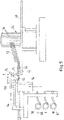
- a device 10 for winding coil windings 12 from individual wires 14 is shown.
- six individual wires 14 each form a coil winding 12.
- the six individual wires 14 are fed via a suitable and known wire feed unit 16, which pulls the individual wires 14 off wire supply coils (not shown).
- the individual wires 14 are guided over a first fixed wire guide 18 and a second fixed wire guide 20, with an individual wire guide 22 which can be rotated with respect to the feed direction being arranged between the two fixed wire guides 18, 20.
- the drive is illustrated schematically by a drive shaft 24 which drives the rotatable single wire guide 22 via a gear train 26 .
- the wire feed device 16 has a separating device, which is known per se and is therefore not shown, in the area of the rotatable individual wire guide 22 .
- the winding coils themselves are wound with the aid of a wire winder 28 known per se with an adjustable winding template 30 around which the individual wires are wound by rotating the entire wire winder 28 .
- a winding start 32 of the coil winding is fixed to a template wire holder 34 rotating with the wire winder 28 .
- the insertion tool 36 shows a movable insertion tool 36, which has a plurality of insertion lamellae 38 arranged in a ring, into which the coil windings 12 are placed.
- the insertion tool 36 also has a coil plate 40 which, in contrast to known embodiments of insertion tools, is designed with first positioning holders 42, 44 for the winding ends 46 and the winding starts 32 already mentioned.
- the entire insertion tool 36 can be rotated relative to the wire winder 28 and moved axially, it being possible for the coil plate 40 to be axially adjustable relative to the insertion lamellae 38 .
- the drive mechanism 46 for adjusting the spool plate 40 and/or the insertion lamellae 38 will not be discussed in detail here.
- a first handling gripper 48 is also shown, which can remove the winding beginnings 32 initially held in the template wire holder 34 and transfer them to a first positioning holder 44 for a winding beginning 32 .
- the winding process takes place in such a way that initially a winding start 32 produced by the rotatable individual wire holder 22 is clamped in the template wire holder 34 . Then the wire winder 28, which can also be used twice or multiple times for the simultaneous winding of several Coil windings 12 may be present, rotated until the desired number of turns of the six individual wires 14 is wound on the winding template 30. Between the individual windings, the rotatable individual wire holder 22 can be rotated through 180° once or several times, so that the arrangement of the individual wires 14 lying next to one another is exchanged.
- the single-wire rotatable holder 22 is rotated by a suitable rotation angle, which may be 360° or more, to twist the wires.
- the individual wires are then rotated in the area of the rotatable individual wire holder 22, so that a winding end 46 of the coil winding 12 that has just been wound and a winding start 32 of the coil winding 12 to be wound next are produced at the same time.
- This is followed by the transfer of the generated coil winding 12 to the insertion tool 36, which is 3 is illustrated.
- FIG 4 which also shows the two handling grippers 48, 50.
- the in 4 coil winding 12 shown is only to be understood as an example.
- suitable winding templates which are axially adjustable, two coil windings 12 that are already wired together can also be wound with a corresponding wire winder, for example, which are then placed together in the insertion tool. This means that the winding starts and ends of these coil windings are already connected, so that only the winding end of one of the two coil windings and the winding start of the other coil winding have to be clamped in the first positioning holders 42, 44. These are then usually at a greater angular distance from one another than in 4 shown.
- the next coil winding 12 can be wound using the wire winder 28, so that there is time to cover the individual wires 14, which are connected to one another by twisting, over a desired length with a slip-on hose 52, which has hitherto been the case had to be carried out as a manual operation.
- Attaching the attachable hoses 52 is in Figures 5 to 11 illustrated.
- figure 5 shows the insertion tool 36 with a coil winding 12 placed therein, the beginning 32 and end 46 of the winding of which are placed in the first positioning holders 42, 44.
- a centering device 54 and a push-on device 56 are shown, which are used to push the push-on hoses 52 onto the winding ends 46 and the winding beginnings 32 with a specific length.
- the slip-on hoses 52 are first pulled off the supply rolls 58, 60, 62, transferred to a magazine 64 and cut to a desired length from the hose supply.
- the attachable hoses 52 made up in this way already occupy a predefined position in the magazine 64 . If no color distinction is desired, for example according to phase association of the ends of the windings to be covered, a single hose color can also be used.
- the magazine 64 can be displaced perpendicularly with respect to the orientation of the attachment tubes 52 so that the desired attachment tube can be aligned with the centering device 54 . This is explained below 6 referred.
- the magazine 64 is shown in partial section, it being equipped with three attachable hoses of different color coding. While the bottom two push-on hoses in the sense of the illustration are secured in the magazine by a movable lock 66 , the top push-on hose 52 is aligned with the centering device 54 and the twisted winding end 46 . The end of the winding 46 or a beginning of the winding 32 to be provided with a slip-on hose are also aligned by suitable turning and, if necessary, adjusting the height of the coil plate 40 .
- a gripper 68 has already been pushed into the slip-on tube 52 to be pulled on.
- a slider 70 has already pushed the attachable hose out of the magazine by a distance, whereby the end of the hose 72 protruding from the magazine 64 can be axially clamped by a driver 74 of the attachable device 56.
- the gripper 68 inserted into the attachable hose 52 has a bearing mandrel 76, a tong device 78 articulated thereon and an actuating tube 80 which encompasses the bearing mandrel and acts on the tong device.
- This gripper is in Figures 9 and 10 illustrated in more detail.
- the actuating tube 80 can be moved axially separately from the mandrel 76, for which purpose an actuating device 82, not explained in any more detail, is provided, which works, for example, with pneumatic actuating cylinders.
- the pliers device 78 is shown in a closed position, in which it fixes the winding end 46 shown here and presses the individual wires 14 together so that their diameter is smaller than the inner diameter of the push-on tube 52 sitting on the actuating tube 80 with slight play.
- the tong device 78 is in a closed state that is minimized with respect to its outer diameter when it is pushed into the attachable tube, with the tong device being transferred to a maximum open state, for example by a return spring, when the actuating tube 80 is pulled back by a certain distance (see Fig 10 ).
- a return spring for example by a return spring
- the driver 74 of the attachment device 56 is displaced axially, taking the attachment hose 52 with it frictionally or positively by means of tooth-like projections (not shown), which engage in the fabric or the elastic material of the hose being used, until the entire Slip-on tube 52 is drawn onto the winding end 46.
- the process for the start of the winding 32 is carried out after a corresponding rotation of the spool plate 40 (see 7 ) repeated, but the assembly can also be done in reverse order.
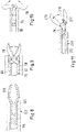
- FIGs 8 and 11 two further exemplary embodiments for grippers 168 and 268 are shown.
- the tong device 178 is formed in one piece with the bearing mandrel 176 as a type of spring fork, the prestressing of which strives to move the tong device 178 into the open state.
- a relative movement of the actuating tube 180 can then close the tong device 178 against the restoring force of the spring fork.
- a gripper 268 is shown, in which the actuating tube 280 acts only on one tong 279 of the tong device 278, while the second tong 277 is rigid with the bearing mandrel 276.
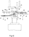
- a disc-shaped tray 88 with second positioning holders 90, 92 is provided on a stator carrier 86, which holds the stator body 84 in a defined position, which when the coil windings 12 take over the winding ends 46 and winding starts 32 clamped in the first positioning holders 42, 44 in the stator support 84 and clamp them.
- first 42, 44 and/or second 90, 92 positioning holders that can be actively adjusted between a released position and a clamped position, or by coordinated clamping forces in passive holders.
- the coil plate 40 of the insertion tool 36 should be moved very close to the disc-shaped support 88 of the stator carrier 86, for which purpose an axial adjustment of the coil plate 40 separate from the insertion lamellae 38 can be helpful.
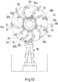
- the diameter of disc-like tray 88 is smaller than the diameter of reel base 40. Referring to FIG 13 this is made possible by the fact that the second positioning holders 90, 92 are formed in multiples, with the winding ends and beginnings being laid down curved in curves which reduce their radial extent.
- the targeted placement in the three positioning holders 90 a, b, c and 92 a, b, c for each winding end 46 and each winding start 32 is carried out by means of a robot gripping device 94.
- the placement in three positioning holders per winding start and winding end has, in addition to the possible reduced diameter of the disc-shaped deposit 88 of the stator carrier 86, which simplifies the handling of the assembled stator carrier 86 in further process steps, also the further advantage that the winding ends 46 and beginnings 32 are placed in an even more precisely defined position, so that gripping in further process steps , e.g. for welding on electrical connection straps, is simplified.
Landscapes
- Engineering & Computer Science (AREA)
- Manufacturing & Machinery (AREA)
- Power Engineering (AREA)
- Manufacture Of Motors, Generators (AREA)
Description
Die Erfindung betrifft ein Verfahren zur Herstellung von Rotoren und Statoren einschließlich der Konfektionierung von Anschlussdrähten gemäß Anspruch 1. Gegenstand der vorliegenden Erfindung ist auch eine Vorrichtung gemäß Anspruch 11 zur Durchführung eines solchen Verfahrens Üblicherweise weist ein solches Verfahren die folgenden Schritte auf:
- Wickeln der aus mehreren Einzeldrähten bestehenden Spulenwicklungen auf einem Drahtwickler, dem die Einzeldrähte über eine Drahtführung von einer Drahtzuführeinheit zugeführt werden,
- Ablegen der Spulenwicklungen in Einziehwerkzeugen,
- Einziehen der Spulenwicklungen in Nuten eines Stator- oder Rotorkörpers,
- phasenweises Zusammenfassen der Einzeldrähte zur Konfektionierung der Anschlussdrähte des jeweiligen Stators oder Rotors.
- Winding the coil windings consisting of several individual wires on a wire winder, to which the individual wires are fed via a wire guide from a wire feed unit,
- Depositing the coil windings in insertion tools,
- Pulling the coil windings into slots of a stator or rotor body,
- phased combination of the individual wires for the assembly of the connection wires of the respective stator or rotor.
Dieses Verfahren hat den Nachtteil, dass es sich nur teilweise automatisieren lässt, weil das Greifen der Einzeldrähte und das Aufziehen oder Aufstecken der Aufsteckschläuche aufgrund der undefinierten Lage der Einzeldrähte manuell durchgeführt werden muss.The disadvantage of this method is that it can only be partially automated because the gripping of the individual wires and the pulling or attaching of the slip-on hoses has to be carried out manually due to the undefined position of the individual wires.
Bekannt ist es z.B. aus der
Die
Hauptmerkmale der Erfindung sind in den Ansprüchen 1 und 11 angegeben. Ausgestaltungen des Verfahrens sind Gegenstand der Ansprüche 2 bis 10, Weiterbildungen der Vorrichtung Gegenstand der Ansprüche 11 bis 16.Main features of the invention are set out in claims 1 and 11. Refinements of the method are the subject matter of claims 2 to 10, further developments of the device are the subject matter of claims 11 to 16.
Das erfindungsgemäße Verfahren sieht vor, dass die Einzeldrähte jeder Spulenwicklung mit den Aufsteckschläuchen konfektioniert werden und vorzugsweise während, unmittelbar vor oder unmittelbar nach ihrem Durchtrennen im Bereich der Drahtführung zur Ausbildung von Wicklungsenden und Wicklungsanfängen aneinander festgelegt werden, die Wicklungsenden und Wicklungsanfänge jeder Wicklung nach dem Wickeln vor oder während des Ablegens in in bestimmten Positionen zu den Einziehwerkzeugen angeordneten ersten Positionshaltern festgelegt werden und beim Einziehen der Spulenwicklungen in den Stator oder Rotor die Wicklungsenden und -anfänge aus den ersten Positionshaltern in in bestimmten Positionen zu dem Statorkörper oder Rotorkörper angeordneten zweite Positionshaltern übergeben werden.The method according to the invention provides that the individual wires of each coil winding are assembled with the slip-on hoses and that the winding ends and winding beginnings of each winding are fixed to one another after the winding, preferably during, immediately before or immediately after they are severed in the area of the wire guide to form the winding ends and beginnings of the winding before or during the laying down in first position holders arranged in specific positions relative to the insertion tools and when the coil windings are being drawn into the stator or rotor, the winding ends and beginnings are transferred from the first position holders to second position holders arranged in specific positions relative to the stator body or rotor body .
Das erfindungsgemäße Verfahren nutzt die in der Drahtzuführeinrichtung noch gegebene definierte Lage der Einzeldrähte einer Wicklung aus, um diese dann an dieser Stelle mittels geeigneter Mittel, auf die später noch näher eingegangen wird, zu fassen und miteinander zu einem Wicklungsanfang und/oder Wicklungsende aneinander festzulegen. Idealerweise werden gleichzeitig an der Trennstelle, an welcher zwei aufeinanderfolgende Spulenwicklungen im Bereich der Drahtzuführeinrichtung durch ein Trennwerkzeug getrennt werden, ein Wicklungsanfang und ein Wicklungsende erzeugt. Durch das Festlegen der Enden der Einzeldrähte aneinander werden die Wicklungsenden und -anfänge stabilisiert und eignen sich für ein automatisiertes Drahthandling. Auf diese Weise kann bis zur endgültigen Konfektionierung eines Stators oder Rotors eine definierte Position sichergestellt werden, so dass die Wicklungsenden und - anfänge im gesamten Prozess bis zum Anbringen von Anschlusslaschen für die elektrischen Anschlüsse der Stators oder Rotors jederzeit von einer geeigneten Handlingvorrichtung für den jeweils anstehenden Bearbeitungsschritt in definierter Lage gegriffen werden können.The method according to the invention uses the defined position of the individual wires of a winding still present in the wire feed device in order to then grasp them at this point by means of suitable means, which will be discussed in more detail later, and fix them together to form a winding beginning and/or winding end. Ideally will at the same time at the separation point, at which two consecutive coil windings are separated by a separating tool in the area of the wire feed device, a winding start and a winding end are produced. By fixing the ends of the individual wires to each other, the ends and beginnings of the winding are stabilized and are suitable for automated wire handling. In this way, a defined position can be ensured until the final assembly of a stator or rotor, so that the ends and beginnings of the windings can be handled at any time by a suitable handling device for the current situation throughout the process up to the attachment of connection lugs for the electrical connections of the stator or rotor processing step can be gripped in a defined position.
In einer bevorzugten Ausführungsform der Erfindung ist vorgesehen, dass die Aufsteckschläuche vor dem Einziehen der Spulenwicklungen in den Stator- oder Rotorkörper auf die Wickelungsenden und/oder -anfänge aufgesteckt werden.In a preferred embodiment of the invention, it is provided that the slip-on hoses are slipped onto the ends and/or beginnings of the windings before the coil windings are drawn into the stator or rotor body.
Den Schritt des Aufziehens bereits zu diesem frühen Zeitpunkt vorzusehen, hat den Vorteil, dass die Wicklungsenden und -anfänge zusätzlich stabilisiert werden und die Einzeldrähte über die Länge des Aufsteckschlauches innerhalb von diesem in einer definierten Lage gehalten werden. Ansonsten bestünde die Gefahr, dass sich Einzeldrähte beim Ablegen in dem Einziehwerkzeug oder beim Einziehen in die Statornuten verformen könnten, wodurch ein späteres, automatisiertes Aufziehen oder Aufstecken der Aufsteckschläuche erschwert sein könnte. Die frühzeitige Umhüllung der zusammengehörigen Einzeldrähte bietet auch den Vorteil, dass die Aufsteckschläuche in allen Verfahrensschritten eine günstige Angriffsfläche für jeweils zum Einsatz kommende Handlingvorrichtungen bieten.Providing the step of pulling on at this early point in time has the advantage that the ends and beginnings of the winding are additionally stabilized and the individual wires are held in a defined position over the length of the slip-on tube within the latter. Otherwise there would be a risk that individual wires could be deformed when they were laid down in the insertion tool or when they were pulled into the stator slots, which could make it difficult for the slip-on hoses to be pulled on or attached automatically later on. The early encasing of the individual wires that belong together also offers the advantage that the slip-on hoses offer a favorable contact surface for the handling devices that are used in each case in all process steps.
Eine bevorzugte Weiterbildung des Verfahrens sieht vor, dass die Einzeldrähte der Wicklungsenden und/oder -anfänge vor dem Aufstecken der Aufsteckschläuche auf einen Durchmesser kompaktiert werden, der kleiner als der Innendurchmesser der Aufsteckschläuche ist. Das Kompaktieren ist so zu verstehen, dass die Einzeldrähte enger aneinander gepresst werden als es ich beim losen Beieinanderliegen der Einzeldrähte ergeben würde. Die Aufsteckschläuche, die meist auf einem elastischen Gewebe bestehen, aber auch aus einem homogenen elastischen Material bestehen können, können dadurch leichter auch die Wicklungsenden oder - anfänge aufgefädelt werden. Wenn die Enden der Einzeldrähte einmal in das Schlauchende eingefädelt sind, kann sich der Aufsteckschlauch kurzen Erweiterungsstellen des Gesamtdurchmessers der Einzeldrähte durch einzelne Ausbiegungen gut anpassen oder auch die ausbauchenden Einzeldrähte auf einen kleineren Gesamtdurchmesser beim Aufstecken zusammendrücken. Die zum Aufschieben erforderliche Kraft wird dadurch nicht wesentlich erhöht.A preferred development of the method provides that the individual wires of the winding ends and/or beginnings are compacted to a diameter that is smaller than the inside diameter of the slip-on tubes before the slip-on tubes are attached. Compacting is to be understood in such a way that the individual wires are pressed closer together than would be the case if the individual wires were lying loosely next to each other. The slip-on hoses, which usually consist of an elastic fabric, but can also consist of a homogeneous elastic material, can also be threaded more easily at the ends or beginnings of the winding. Once the ends of the individual wires have been threaded into the end of the hose, the slip-on hose can adapt well to short expansion points in the overall diameter of the individual wires through individual bends or even the bulging ones Press the individual wires together to a smaller overall diameter when plugging them in. This does not significantly increase the force required to slide it on.
Besonders bevorzugt wird das Verfahren dahingehend weitergebildet, dass die Einzeldrähte zur Ausbildung der Wicklungsenden und/oder -anfänge miteinander verdrillt werden. Das Verdrillen hat gegenüber anderen Alternativen, wie z.B. dem Verschweißen oder Verkleben der Einzeldrähte oder dem Anbringen einer Manschette um die Einzeldrähte, den Vorteil, dass es sich sehr einfach automatisiert durchführen lässt und in den weiteren Verfahrensschritten keine Besonderheiten durch die Art der Verbindung der Einzeldrähte berücksichtigt werden müssen.The method is particularly preferably developed such that the individual wires are twisted together to form the ends and/or beginnings of the winding. Twisting has the advantage over other alternatives, such as welding or gluing the individual wires or attaching a sleeve around the individual wires, that it can be automated very easily and in the further process steps no special features due to the type of connection of the individual wires are taken into account Need to become.
Das Verdrillen kann zum Beispiel in der Weise einfach durchgeführt werden, dass die Einzeldrähte im Bereich der Drahtzuführeinrichtung durch eine Einzeldrahtführung geführt werden, die um eine Drehachse parallel zur Drahtführrichtung drehbar ist. Die Einzeldrahtführung weist entsprechend der Anzahl der Einzeldrähte Führungen auf, die an einem gemeinsamen Halter angeordnet sind, der in der genannten Art und Weise drehbar ist. Damit lassen sich die Einzeldrähte miteinander verdrillen, indem die Einzeldrahtführung um einen geeigneten Drehwinkel gedreht wird, bis die gewünschte Verdrillung erreicht wird. Die drehbare Einzeldrahtführung ist hierzu in der Regel zwischen zwei starren Drahtführungen angeordnet, die den Gegenhalt bilden, so dass das Verdrillen nur in einem gewünschten Endbereich stattfindet, der die Wicklungsenden oder -anfänge ausbildet. Nach dem Verdrillen werden die Drähte dann im verdrillten Bereich durchtrennt, so dass eine Hälfte das Wicklungsende der vorausgehenden Wickelung und die andere Hälfte den Wicklungsanfang der nachfolgenden Wicklung bildet. Durch das Verdrillen werden die Einzeldrähte auch zu einer verjüngten Spitze als Beispiel für eine Kompaktierung geformt.Twisting can, for example, be carried out simply by guiding the individual wires in the area of the wire feed device through an individual wire guide which can be rotated about an axis of rotation parallel to the wire guide direction. The individual wire guide has guides corresponding to the number of individual wires, which are arranged on a common holder which can be rotated in the manner mentioned. This allows the individual wires to be twisted together by rotating the individual wire guide through a suitable angle of rotation until the desired twist is achieved. For this purpose, the rotatable single wire guide is usually arranged between two rigid wire guides, which form the counter support, so that the twisting takes place only in a desired end region, which forms the ends or beginnings of the winding. After twisting, the wires are then severed in the twisted area so that one half forms the end of the winding for the preceding winding and the other half forms the beginning of the winding for the following winding. Twisting also forms the strands into a tapered tip as an example of compaction.
Die drehbare Einzeldrahtführung hat den weiteren Vorteil, dass mit ihr auch während eines Wickelvorgangs die Lage der Einzeldrähte zueinander um beispielsweise 180° gedreht werden kann. Es hat sich gezeigt, dass sich mit derartigen Spulenwicklungen die elektrischen Verluste der hergestellten Stators vermindern lassen.The rotatable individual wire guide has the further advantage that it can also be used to rotate the position of the individual wires relative to one another by 180°, for example, during a winding process. It has been shown that the electrical losses of the stator produced can be reduced with coil windings of this type.
Alternativ oder ergänzend zu der Kompaktierung der Einzeldrähte an den Enden der Wicklungsenden oder Wicklungsanfänge kann vorgesehen sein, dass der Innendurchmesser der Aufsteckschläuche an der Aufsteckseite vor dem Aufstecken auf die Wicklungsenden und/oder -anfänge aufgeweitet wird. Hierzu kann beispielsweise ein Konus in den Aufsteckschlauch eingesteckt werden, über dessen erweitertes Ende dann die ggf. kompaktierten Einzeldrähte der Wicklungsenden oder -anfänge in den jeweiligen Aufsteckschlauch eingeführt werden.As an alternative or in addition to the compaction of the individual wires at the ends of the winding ends or beginnings of the winding, it can be provided that the inner diameter of the push-on hoses on the attachment side is widened before being pushed onto the ends and/or beginnings of the winding. For this purpose, for example, a cone can be inserted into the push-on tube be, via the expanded end then the possibly compacted individual wires of the winding ends or beginnings are inserted into the respective slip-on tube.
Eine zweckmäßige Weiterbildung des Verfahrens sieht vor, dass die Aufsteckschläuche zu den Wicklungsenden und/oder -anfängen mittels einer Zentriervorrichtung ausgerichtet werden, die in den jeweiligen Aufsteckschlauch eingeschoben wird. Durch dieses Aufspannen der Aufsteckschläuche sind diese einfacher zu handhaben und können ihre Form im Prozess auch nicht ändern, so dass die Prozesssicherheit erhöht wird.An expedient development of the method provides that the slip-on hoses are aligned to the ends and/or beginnings of the winding by means of a centering device that is pushed into the respective slip-on hose. By stretching the slip-on hoses in this way, they are easier to handle and cannot change their shape during the process, so that process reliability is increased.
Zur bevorzugten Weiterbildung des Verfahrensschrittes des Zentrierens ist vorgesehen, dass die Zentriervorrichtung einen beweglichen Greifer aufweist, mit welchem die Wicklungsenden oder -anfänge gegriffen und kompaktiert werden. Auf diese Weise wird durch die durch den Aufsteckschlauch geführten Greifer ein Ausrichten und ein Fixieren des Aufsteckschlauches relativ zu einem Wicklungsende oder Wicklungsanfang erreicht. Gleichzeitig vereinfacht der Greifer durch das Zusammendrücken und damit Kompaktieren der Einzeldrähte das Aufstecken, -ziehen oder -schieben des Aufsteckschlauches auf die Drähte.For the preferred development of the method step of centering, it is provided that the centering device has a movable gripper with which the winding ends or beginnings are gripped and compacted. In this way, the grippers guided through the slip-on hose achieve alignment and fixing of the slip-on hose relative to a winding end or start. At the same time, the gripper simplifies the pushing, pulling or pushing of the push-on hose onto the wires by pressing together and thus compacting the individual wires.
Eine bevorzugte Weiterbildung zur Handhabung der Aufsteckschläuche sieht vor, dass die Aufsteckschläuche vor dem Aufstecken auf eine bestimmte Länge konfektioniert und in einem Magazin aufgenommen werden, durch welches die Position der Aufsteckschläuche relativ zu der Zentriervorrichtung definiert wird, z.B. indem dieses als Teil der Zentriervorrichtung ausgebildet ist.A preferred further development for handling the detachable hoses provides that the detachable hoses are cut to a specific length before being attached and are accommodated in a magazine, which defines the position of the detachable hoses relative to the centering device, e.g. in that this is designed as part of the centering device .
Eine weitere bevorzugte Maßnahme zur Verbesserung des Handlings der Wicklungsenden und Wicklungsanfänge sowie des fertigen Stators besteht darin, dass die mit den Aufsteckschläuchen umhüllten Wicklungsenden und/oder -anfänge in jeweils mehreren zweiten Positionshaltern mit Bezug auf den Rotor- oder Statorkörper fixiert werden. Auf diese Weise können die Wicklungsenden und -anfänge in gekrümmten Kurven auf scheibenförmigen Ablagen abgelegt werden, die einem Stator- oder Rotorträger zugeordnet sind, in dem der mit den Spulenwicklungen bestückte Rotor oder Stator gehalten ist. Das definierte Ablegen erleichtert zum einen das maschinelle Wiederaufnehmen der Wicklungsenden und -anfänge und zum anderen kann der Durchmesser der scheibenförmigen Ablage verringert werden, so dass die Abmessungen des Statorträgers ingesamt reduziert werden können, was wiederum dessen Handling zu Gute kommt.A further preferred measure for improving the handling of the winding ends and beginnings and the finished stator is that the winding ends and/or beginnings covered with the slip-on hoses are fixed in a plurality of second position holders in relation to the rotor or stator body. In this way, the winding ends and beginnings can be deposited in curved curves on disc-shaped deposits which are assigned to a stator or rotor support in which the rotor or stator fitted with the coil windings is held. On the one hand, the defined placement facilitates the mechanical picking up of the winding ends and beginnings and, on the other hand, the diameter of the disc-shaped deposit can be reduced, so that the overall dimensions of the stator carrier can be reduced, which in turn benefits its handling.
Grundsätzlich ist noch anzumerken, dass das Verfahren zunächst nur für einen Teil der Spulenwicklungen, zum Beispiel den Wicklungen einer Phase durchgeführt und dann für die übrigen Phasen oder verbleibenden Spulenwicklungen wiederholt werden kann.In principle, it should also be noted that the method can initially only be carried out for part of the coil windings, for example the windings of one phase, and then repeated for the other phases or remaining coil windings.
Gegenstand der vorliegenden Erfindung ist auch eine Vorrichtung zur Durchführung des zuvor beschriebenen Verfahrens. Neben den Vorrichtungsmerkmalen:
- einer Drahtzuführeinrichtung zum parallelen Zuführen von Einzeldrähten, die gemeinsam eine Spulenwicklung für einen Stator oder Rotor eines Elektromotors bilden,
- eines Drahtwickler mit Wicklungsschablonen, auf welchen die Spulenwicklungen sukzessive gewickelt werden, wobei ein Schablonengreifer zum Halten der Anfänge der Einzeldrähte an dem Drahtwickler vorgesehen ist,
- einem Einziehwerkzeug zur Aufnahme der Spulenwicklungen nach dem Wickeln,
- eines Stator- oder Rotorträger zur Aufnahme eines Stator- oder Rotorkörpers,
- und einer Übertragungsvorrichtung zum Übertragen der Spulenwicklungen von dem Einziehwerkzeug in den Stator- oder Rotorkörper,
- a wire feeding device for the parallel feeding of individual wires which together form a coil winding for a stator or rotor of an electric motor,
- a wire winder with winding templates on which the coil windings are successively wound, with a template gripper being provided to hold the beginnings of the individual wires on the wire winder,
- a pull-in tool for picking up the coil windings after winding,
- a stator or rotor carrier for receiving a stator or rotor body,
- and a transfer device for transferring the coil windings from the insertion tool into the stator or rotor body,
Die Zentriervorrichtung dient der Handhabung der in sich nur bedingt formstabilen Aufsteckschläuche, zu deren Ausrichtung in Bezug auf die Wicklungsenden und -anfänge sowie vor allem dazu, die Wicklungsenden und -anfänge durch die aufgesteckten Schläuche für weitere Prozessschritte noch besser handhabbar zu machen.The centering device is used to handle the only partially dimensionally stable attachable hoses, to align them in relation to the ends and beginnings of the winding and, above all, to make the ends and beginnings of the winding easier to handle with the attached hoses for further process steps.
Durch diese Ergänzung werden aus den bislang schwer kontrollierbaren abgeschnittenen Einzeldrähten an den Enden und Anfängen der Wicklungen maschinell handhabbare Wicklungsenden und -anfänge geformt, die den Einsatz geeigneter Greifer zur Automatisierung von Einzelschritten im Herstellungsvorgang eines Stators oder Rotors ermöglichen.With this addition, machine-manageable winding ends and beginnings are formed from the previously difficult to control cut individual wires at the ends and beginnings of the windings, which enable the use of suitable grippers to automate individual steps in the manufacturing process of a stator or rotor.
In einer bevorzugten Weiterbildung der erfindungsgemäßen Vorrichtung ist vorgesehen, dass die Verbindungsvorrichtung eine Einzeldrahtführung im Bereich der Drahtzuführeinrichtung aufweist, die um eine Drehachse parallel zur Zuführrichtung der Einzeldrähte zum Drahtwickler drehbar ist.In a preferred development of the device according to the invention, it is provided that the connecting device has a single wire guide in the area of the wire feed device which is rotatable about an axis of rotation parallel to the feed direction of the individual wires to the wire winder.
Die drehbare Einzeldrahtführung kann zunächst die Aufgabe erfüllen, durch eine Rotation die gewünschte Verdrillung der Einzeldrähte herbeizuführen. Hierbei werden die erzeugten Wicklungsenden und -anfänge auch in vorteilhafter Weise verjüngt, d.h. kompaktiert.The rotatable individual wire guide can initially fulfill the task of bringing about the desired twisting of the individual wires by rotation. In this way, the winding ends and beginnings produced are also advantageously tapered, i.e. compacted.
Eine besonders bevorzugte Weiterbildung der Vorrichtung sieht vor, dass in definierter Lage zu den Einziehwerkzeugen erste Positionshalter für die Wicklungsenden und Wicklungsanfänge und in definierter Lage zu der Übertragungsvorrichtung zweite Positionshalter für die Wicklungsanfänge und Wicklungsenden vorgesehen sind.A particularly preferred further development of the device provides that first position holders for the winding ends and winding beginnings are provided in a defined position relative to the insertion tools, and second position holders for the winding beginnings and winding ends in a defined position relative to the transmission device.
Ein bevorzugte Weiterbildung der Zentriervorrichtung sieht vor, dass diese einen Greifer zum Greifen und Kompaktieren der Wicklungsenden oder Wicklungsanfänge aufweist, der durch den Innendurchmesser der Aufsteckschläuche durchführbar ist. Diese Ausführungsform bietet den Vorteil, dass sie gleichzeitig der Stabilisierung der Aufsteckschläuche und der relativen Ausrichtung von diesen zu den Wicklungsenden- und anfängen dient.A preferred development of the centering device provides that it has a gripper for gripping and compacting the ends or beginnings of the winding, which can be passed through the inside diameter of the slip-on hoses. This embodiment offers the advantage that it simultaneously serves to stabilize the slip-on hoses and align them relative to the ends and beginnings of the winding.
Eine weitere bevorzugte Ausgestaltung der Aufsteckvorrichtung sieht vor, dass diese wenigstens einen Mitnehmer zum Greifen und Aufziehen oder Aufstecken der Aufsteckschläuche auf die Wicklungsenden oder -anfänge aufweist. Nachdem der Greifer den Aufsteckschlauch ausgerichtet und das jeweilige Wicklungsende oder den jeweiligen Wicklungsanfang fixiert hat, greifen die Mitnehmer den Aufsteckschlauch und schieben ihn über den Greifer und das verjüngte Ende auf das jeweilige Wicklungsende oder den jeweiligen Wicklungsanfang. Die Mitnehmer können zangenartig ausgebildet sein und den Schlauch reibschlüssig mitnehmen, bei einem Gewebeschlauch oder auch einem gummiartigen Schlauch können aber kleine kurze Vorsprünge für eine formschlüssige Mitnahme sorgen.A further preferred embodiment of the push-on device provides that it has at least one carrier for gripping and pulling or pushing the push-on hoses onto the ends or beginnings of the winding. After the gripper has aligned the slip-on tube and fixed the respective winding end or the respective winding start, the drivers grip the slip-on tube and push it over the gripper and the tapered end onto the respective winding end or the respective winding start. The drivers can be designed like pliers and take the hose with them by friction, but in the case of a fabric hose or also a rubber-like hose, small, short projections can ensure positive driving.
Eine bevorzugte Weiterbildung des Greifers kann vorsehen, dass dieser eine Zangenvorrichtung und ein axial zur Zangenvorrichtung bewegliches Betätigungsrohr aufweist, das durch axiales Zustellen die Zangenvorrichtung in eine Schließstellung bewegt. Diese Ausführungsform baut im Durchmesser sehr kompakt und lässt sich auf den Durchmesser der Aufsteckschläuche abstimmen, wobei das Betätigungsrohr unmittelbar zur Zentrierung des ihn umgebenden Aufsteckschlauches genutzt werden kann.A preferred development of the gripper can provide that it has a tong device and an actuating tube that can be moved axially with respect to the tong device and that moves the tong device into a closed position by axially advancing it. This embodiment has a very compact diameter and can be matched to the diameter of the push-on hoses, with the actuating tube being able to be used directly for centering the push-on hose surrounding it.
Weitere Merkmale, Einzelheiten und Vorteile der Erfindung ergeben sich aus dem Wortlaut der Ansprüche sowie aus der folgenden Beschreibung von Ausführungsbeispielen anhand der Zeichnungen. Es zeigen:
-
Fig. 1 eine schematische Ansicht einer Vorrichtung zur Herstellung von Spulenwicklungen; -
Fig. 2 eine Ansicht eines Einziehwerkzeuges zur Aufnahme von Spulenwicklungen; -
Fig. 3 eine schematische Ansicht des Übergabevorgangs der Spulenwicklungen vom Drahtwickler an das Einziehwerkzeug; -
Fig. 4 eine schematische Draufsicht auf einen Spulenteller des Einziehwerkzeuges mi einer übergebenen Spulenwickung; -
Fig. 5 eine schematische Seitenansicht einer Vorrichtung zur Bestückung der Wicklungsenden und -anfänge mit Aufsteckschläuchen; -
Fig. 6 eine Detailansicht einer Zentriervorrichtung der Bestückungsvorrichtung; -
Fig. 7 eine schematische Draufsicht auf die Zentriervorrichtung; -
Fig. 8 einen schematischen Schnitt einer ersten Ausführungsform eines Greifers der Zentriervorrichtung; -
Fig. 9 einen schematischen Schnitt einer zweiten Ausführungsform eines Greifers der Zentriervorrichtung in halb geschlossener Stellung; -
Fig. 10 einen Schnitt des Greifers nachFig. 9 in der geöffneten Stellung; -
Fig. 11 einen schematischen einer weiteren Ausführungsform eines Greifers der Zentriervorrichtung; -
Fig. 12 eine schematische Ansicht des Einziehens der Spulenwicklungen in einen Statorkörper; -
Fig. 13 eine Ansicht des Statorträgers aus Fige. 12 von unten mit einem Positionierungsgreifer.
-
1 a schematic view of a device for the production of coil windings; -
2 a view of a pull-in tool for receiving coil windings; -
3 a schematic view of the process of transferring the coil windings from the wire winder to the insertion tool; -
4 a schematic plan view of a spool plate of the insertion tool with a transferred spool winding; -
figure 5 a schematic side view of a device for equipping the winding ends and beginnings with slip-on hoses; -
6 a detailed view of a centering device of the placement device; -
7 a schematic plan view of the centering device; -
8 a schematic section of a first embodiment of a gripper of the centering device; -
9 a schematic section of a second embodiment of a gripper of the centering device in the half-closed position; -
10 a cut of the gripper9 in the open position; -
11 a schematic of a further embodiment of a gripper of the centering device; -
12 a schematic view of the retraction of the coil windings in a stator body; -
13 a view of the stator from Fige. 12 from below with a positioning gripper.
In
Das Wickeln der Wickelspulen selbst erfolgt mit Hilfe eines an sich bekannten Drahtwicklers 28 mit einer verstellbaren Wickelschablone 30, um die die Einzeldrähte durch eine Drehbewegung des gesamten Drahtwicklers 28 gewickelt werden. Ein Wicklungsanfang 32 der Spulenwicklung ist dabei an einem mit dem Drahtwickler 28 rotierenden Schablonendrahthalter 34 fixiert.The winding coils themselves are wound with the aid of a
In
Der Wicklungsvorgang läuft so ab, dass zunächst ein durch den drehbaren Einzeldrahthalter 22 erzeugter Wicklungsanfang 32 in dem Schablonendrahthalter 34 verklemmt wird. Anschließend wird der Drahtwickler 28, der auch doppelt oder mehrfach zum gleichzeitigen Wickeln mehrerer Spulenwicklungen 12 vorhanden sein kann, gedreht, bis die gewünschte Windungszahl der sechs Einzeldrähte 14 auf der Wickelschablone 30 aufgewickelt ist. Zwischen den einzelnen Windungen kann der drehbare Einzeldrahthalter 22 einmalig oder mehrmals um 180° gedreht werden, so dass die Anordnung der nebeneinander liegenden Einzeldrähte 14 getauscht wird.The winding process takes place in such a way that initially a winding
Nach Abschluss des Wickelvorgangs wird der drehbare Einzeldrahthalter 22 zum Verdrillen der Drähte um einen geeigneten Drehwinkel gedreht, der 360° oder mehr betragen kann. Anschließend werden die Einzeldrähte im Bereich der drehbaren Einzeldrahthalterung 22 gedreht, so dass gleichzeitig ein Wicklungsende 46 der soeben gewickelten Spulenwicklung 12 und ein Wicklungsanfang 32 der als nächstes zu wickelnden Spulenwicklung 12 erzeugt wird. Es schließt sich dann die Übergabe der erzeugten Spulenwicklung 12 an das Einziehwerkzeug 36 an, die in
In
In
Nach dem Ablegen der gewickelten Spulenwicklung 12 im Einziehwerkzeug 36 kann die nächste Spulenwicklung 12 mittels des Drahtwicklers 28 gewickelt werden, so dass Zeit zur Verfügung steht, die durch das Verdrillen miteinander verbundenen Einzeldrähte 14 über eine gewünschte Länge mit einem Aufsteckschlauch 52 zu überziehen, was bislang als manueller Vorgang durchgeführt werden musste.After the wound coil winding 12 has been placed in the
Das Aufstecken der Aufsteckschläuche 52 ist in
Das Magazin 64 kann senkrecht in Bezug auf die Ausrichtung der Aufsteckschläuche 52 verlagert werden, so dass der gewünschte Aufsteckschlauch in Flucht zu der Zentriervorrichtung 54 gelangen kann. Hierzu wird im Folgenden auf
In der in
Der in den Aufsteckschlauch 52 eingeschobene Greifer 68 besitzt bei der gezeigten Ausführungsbeispiel einen Lagerdorn 76, eine daran gelenkig gelagerten Zangenvorrichtung 78 sowie ein den Lagerdorn umfassendes Betätigungsrohr 80, das auf die Zangenvorrichtung wirkt. Dieser Greifer ist in
Die Zangenvorrichtung 78 befindet sich beim Einschieben in den Aufsteckschlauch in einem bezüglich ihres Außendurchmessers minimierten Schließzustand, wobei die Zangenvorrichtung z.B. durch eine Rückstellfeder in einem maximal geöffneten Zustand überführt wird, wenn das Betätigungsrohr 80 um ein bestimmtes Wegstück zurückgezogen wird (siehe
Nach diesem Vorgang wird der Mitnehmer 74 der Aufsteckvorrichtung 56 axial verlagert, wobei er den Aufsteckschlauch 52 reibschlüssig oder durch zahnartige Vorsprünge (nicht gezeigt), die in das Gewebe oder das elastische Material des jeweils zum Einsatz kommenden Schlauches eingreifen, formschlüssig mitnimmt, bis der gesamte Aufsteckschlauch 52 auf das Wicklungsende 46 aufgezogen ist. Nachdem das Wicklungsende 46 mit einem Aufsteckschlauch 52 versehen worden ist, wir der Vorgang für den Wicklungsanfang 32 nach einem entsprechenden Drehen des Spulentellers 40 (siehe
In
In
In
In
Die Erfindung ist nicht auf eine der vorbeschriebenen Ausführungsformen beschränkt, sondern in vielfältiger Weise abwandelbar.The invention is not limited to one of the embodiments described above, but can be modified in many ways.
Sämtliche aus den Ansprüchen, der Beschreibung und der Zeichnung hervorgehenden Merkmale und Vorteile, einschließlich konstruktiver Einzelheiten, räumlicher Anordnungen und Verfahrensschritten, können sowohl für sich als auch in den verschiedensten Kombinationen erfindungswesentlich sein.
Claims (16)
- Method for producing rotors and stators of electric motors including the tailoring of connecting wires, which has the following steps:- winding the coil windings (12) consisting of several individual wires (14) on a wire winder (28), to which the individual wires (14) are supplied via a wire guide (18, 20, 22) from a wire supply unit (16),- placing the coil windings (12) in an insertion tool (36),- inserting the coil windings (12) into grooves of a stator body (84) or rotor body,- phased combining of the individual wires (14)- assembly of the connecting wires of the respective stator or rotor by means of slipping on slip-on tubes (52) by means of a centring device (54) and slip-on device (56),wherein the individual wires (14) of each coil winding (12) in the region of the wire guide (18, 20, 22) are fixed next to one another to form winding ends (46) and winding beginnings (32), after the winding, the winding ends (46) and winding beginnings (32) of each coil winding (12) are fixed prior to or during the placing in first position holders (42, 44) arranged in specific positions with regard to the insertion tool, and when the coil windings (12) are drawn into the stator or rotor, the winding ends (46) and winding beginnings (32) are transferred from the first position holders (42, 44) into second position holders (90, 92) arranged in specific positions with regard to the stator body (84) or rotor body.
- Method according to claim 1, characterised in that the slip-on tubes (52) are slipped onto the winding ends (46) and/or winding beginnings (32) before the coil windings (12) are inserted into the stator body (84) or rotor body.
- Method according to claim 1 or 2, characterised in that, before the slip-on tubes (52) are slipped on, the individual wires (14) of the winding ends (46) and/or winding beginnings (32) are compacted to a diameter which is smaller than the inner diameter of the slip-on tubes (52).
- Method according to any of the preceding claims, characterised in that the individual wires (14) are twisted together to form the winding ends (46) and/or winding beginnings (32).
- Method according to any of the preceding claims, characterised in that in the region of the wire supply unit (16) the individual wires (14) are guided through an individual wire guide (22) which is rotatable about a rotational axis parallel to the wire guide direction.
- Method according to any of the preceding claims, characterised in that the inner diameter of the slip-on tubes (52) is widened at the slip-on-side prior to being slipped onto the winding ends (46) and/or winding beginnings (32).
- Method according to any of the preceding claims, characterised in that the slip-on tubes (52) are aligned with respect to the winding ends (46) and/or winding beginnings (32) by means of a centring device (54) which engages into the respective slip-on tube (52).
- Method according to claim 7, characterised in that the centring device (54) has a movable gripper (68) with which the winding ends (46) or winding beginnings (32) are gripped and compacted.
- Method according to claim 7 or 8,characterised in that the slip-on tubes (52) are tailored to a specified length prior to the slipping-on and are accommodated in a magazine (64) by means of which the position of the slip-on tubes (52) relative to the centring device (54) is defined.
- Method according to any of the preceding claims, characterised in that the winding ends (46) and/or winding beginnings (32) sheathed with the slip-on tubes (52) are fixed in respectively several second position holders (90 a, b, c, 92 a, b,c) with regard to the rotor body or stator body (84).
- Device for carrying out a method according to any of the preceding claims, having the following characteristics:- a wire supply unit (16) for the parallel supply of individual wires (14), which together form a coil winding (12) for a stator or rotor of an electric motor,- a wire winder (28) with winding templates (30), onto which the coil windings (12) are successively wound, wherein a template wire gripper (34) is provided for holding the beginnings of the individual wires on the wire winder (28),- an insertion tool (36) for receiving the coil windings (12) after the winding,- a stator carrier (86) or rotor carrier for receiving a stator body (84) or rotor body,- a transfer device for transferring the coil windings (12) from the insertion tool (36) into the stator body (84) or rotor body,wherein furthermore at least one connecting device is provided with which the wire beginnings and/or wire ends of the individual wires (14) are connected with one another to form winding ends (46) or winding beginnings (32), wherein
a centring device (54) for aligning, and a slip-on device (56) for slipping on slip-on tubes (52) onto the respective winding end (46) or the respective winding beginning (32), are provided. - Device according to claim 11, characterised in that the connecting device has an individual wire guide (22) in the region of the wire supply device (16) which is rotatable about a rotational axis parallel to the supply direction of the individual wires (14) to the wire winder (28).
- Device according to claim 11 or 12, characterised in that first position holders (42, 44) for the winding ends (46) and winding beginnings (32) are provided in a defined position in regard to the insertion tool (36), and that second position holders (90, 92) for the winding beginnings (32) and winding ends (46) are provided in a defined position in regard to the transfer device.
- Device according to any of claims 11 to 13, characterised in that the centring device (54) has a gripper (68) for gripping and compacting the winding ends (46) or winding beginnings (32) which can be guided through the inner diameter of the slip-on tubes (52).
- Device according to any of claims 11 to 14, characterised in that the centring device (54) has at least one driver (74) for gripping and drawing on or slipping on the slip-on tubes (52) onto the winding ends (46) or winding beginnings (32).
- Device according to claim 14, characterised in that the gripper (68) has a plier apparatus (78) and an actuating pipe (80), movable axially with respect to the plier apparatus (78), which moves the plier apparatus (78) into a closed position by means of axial approach.
Applications Claiming Priority (2)
| Application Number | Priority Date | Filing Date | Title |
|---|---|---|---|
| DE102018100016.2A DE102018100016A1 (en) | 2018-01-02 | 2018-01-02 | Method and device for the production of rotors and stators, including the assembly of connecting wires |
| PCT/EP2018/086316 WO2019134849A1 (en) | 2018-01-02 | 2018-12-20 | Method and device for producing rotors and stators including the production of connection wires |
Publications (2)
| Publication Number | Publication Date |
|---|---|
| EP3735737A1 EP3735737A1 (en) | 2020-11-11 |
| EP3735737B1 true EP3735737B1 (en) | 2022-08-31 |
Family
ID=64900955
Family Applications (1)
| Application Number | Title | Priority Date | Filing Date |
|---|---|---|---|
| EP18826682.9A Active EP3735737B1 (en) | 2018-01-02 | 2018-12-20 | Method and device for producing rotors and stators including the production of connection wires |
Country Status (6)
| Country | Link |
|---|---|
| US (1) | US11539274B2 (en) |
| EP (1) | EP3735737B1 (en) |
| KR (1) | KR102661986B1 (en) |
| CN (1) | CN111670534B (en) |
| DE (1) | DE102018100016A1 (en) |
| WO (1) | WO2019134849A1 (en) |
Families Citing this family (4)
| Publication number | Priority date | Publication date | Assignee | Title |
|---|---|---|---|---|
| DE102018100016A1 (en) * | 2018-01-02 | 2019-07-04 | Elmotec Statomat Holding GmbH | Method and device for the production of rotors and stators, including the assembly of connecting wires |
| CN111181331B (en) * | 2020-03-02 | 2020-11-10 | 江苏卓燃工程咨询有限公司 | Motor rotor winding machine |
| IT202100011564A1 (en) * | 2021-05-06 | 2022-11-06 | Marsilli S P A | Method for making a stator for electric motors. |
| KR102299535B1 (en) * | 2020-12-14 | 2021-09-09 | 주식회사 야호텍 | Apparatus of winding coil |
Family Cites Families (30)
| Publication number | Priority date | Publication date | Assignee | Title |
|---|---|---|---|---|
| GB1141136A (en) * | 1966-07-28 | 1969-01-29 | Gen Electric | Method and apparatus for developing coils in inductive devices |
| US3675300A (en) * | 1970-08-28 | 1972-07-11 | Essex International Inc | Lead wire inserting mechanism for stator winding apparatus |
| CH652538A5 (en) * | 1981-01-29 | 1985-11-15 | Micafil Ag | DEVICE FOR CONNECTING THE WINDING ENDS TO THE TERMINALS OF STATORS OF ELECTRICAL MACHINES AND A METHOD FOR OPERATING THE SAME. |
| DE3114407A1 (en) * | 1981-04-09 | 1982-11-11 | Balzer & Dröll GmbH, 6369 Niederdorfelden | METHOD AND DEVICE FOR WINDING AND PULLING IN COILS IN THE SLOTS OF STATOR AND ROTOR SHEET PACKAGES OF ELECTRICAL MACHINES |
| US4951379A (en) * | 1989-09-25 | 1990-08-28 | Globe Products Inc. | Method for connecting wires to terminals having tangs and cutting the wires at the terminals |
| EP0468307A3 (en) * | 1990-07-27 | 1993-08-11 | Axis S.P.A. | Methods and apparatus for processing stators |
| US5065503A (en) * | 1990-08-01 | 1991-11-19 | Axis, U.S.A., Inc. | Apparatus for connecting stator coil leads |
| US5535503A (en) * | 1993-12-03 | 1996-07-16 | Globe Products Inc. | Stator lead wire connection method and apparatus |
| US5542456A (en) * | 1994-07-26 | 1996-08-06 | Odawara Engineering Co., Ltd. | Coil wire handling apparatus |
| JPH08163837A (en) * | 1994-12-02 | 1996-06-21 | Matsushita Electric Ind Co Ltd | Method and machine for manufacturing winding of stator coil |
| DE19815088A1 (en) * | 1998-04-06 | 1999-10-07 | Otto Rist | Device for the production of coil windings in stator laminations |
| DE19817370A1 (en) * | 1998-04-18 | 1999-10-21 | Statomat Spezialmaschinen | Method, device and transfer tool for winding and pulling in coils in electrical machine stators |
| DE19824920A1 (en) * | 1998-06-04 | 1999-12-09 | Statomat Spezialmaschinen | Method for producing a stator for electrical machines and pull-in tool part for carrying out the method |
| DE19860413A1 (en) * | 1998-12-28 | 2000-06-29 | Abb Research Ltd | Reinforced, pressure-resistant hose for mechanical winding head support of rotating electrical machines |
| CA2331568A1 (en) * | 1999-03-12 | 2000-09-21 | Raffaele Becherucci | Manufacturing method and apparatus of dynamo-electric machine having stator coils leads at final attachment points before insertion into a stator core |
| US6308744B1 (en) * | 1999-06-14 | 2001-10-30 | Axis Usa, Inc. | Method and apparatus for placing wire coils with varied lengths on dynamo electric motor stators |
| DE10023204A1 (en) * | 2000-05-12 | 2001-11-15 | Alstom Power Nv | Insulation of stator windings with shrink sleeves |
| DE10246423A1 (en) * | 2002-10-04 | 2004-04-15 | Robert Bosch Gmbh | Winding machine for forming windings for electrical machine, has winding template and deflecting member which are mutually displaceable |
| US7370401B2 (en) * | 2003-04-03 | 2008-05-13 | Atop S.P.A. | Apparatus and methods for wire coil lead placement |
| JP4461833B2 (en) * | 2003-04-21 | 2010-05-12 | アイシン・エィ・ダブリュ株式会社 | Coil forming device |
| WO2005027314A1 (en) | 2003-09-10 | 2005-03-24 | Aisin Aw Co., Ltd. | Jig, method, and device for assembling coil |
| DE102004059087A1 (en) * | 2004-12-08 | 2006-06-14 | Robert Bosch Gmbh | Winding device for a field coil, manufacturing device and electrical machine |
| JP4502912B2 (en) * | 2005-09-16 | 2010-07-14 | 三菱電機株式会社 | Rotating electric machine and manufacturing method thereof |
| JP5641635B2 (en) * | 2009-04-24 | 2014-12-17 | 日特エンジニアリング株式会社 | Winding machine and method of manufacturing continuous coil using the same |
| CN201430474Y (en) * | 2009-06-17 | 2010-03-24 | 上海锐奇工具股份有限公司 | End-plate-free stator |
| US8096046B2 (en) * | 2009-11-18 | 2012-01-17 | Remy Technologies L.L.C. | Apparatus for loading stator windings into a stator core |
| DE102010034180A1 (en) * | 2010-08-12 | 2012-02-16 | Otto Rist Gmbh & Co. Kg | Workpiece holder for a stator pack |
| JP5997558B2 (en) * | 2012-09-24 | 2016-09-28 | 株式会社日立産機システム | Rotating electric machine |
| DE102015120661A1 (en) * | 2015-11-27 | 2017-06-01 | Elmotec Statomat Vertriebs Gmbh | Method for producing a coil winding for insertion into radially open slots of stators or rotors of electric machines |
| DE102018100016A1 (en) | 2018-01-02 | 2019-07-04 | Elmotec Statomat Holding GmbH | Method and device for the production of rotors and stators, including the assembly of connecting wires |
-
2018
- 2018-01-02 DE DE102018100016.2A patent/DE102018100016A1/en not_active Withdrawn
- 2018-12-20 CN CN201880085204.6A patent/CN111670534B/en active Active
- 2018-12-20 WO PCT/EP2018/086316 patent/WO2019134849A1/en unknown
- 2018-12-20 KR KR1020207020733A patent/KR102661986B1/en active IP Right Grant
- 2018-12-20 US US16/959,676 patent/US11539274B2/en active Active
- 2018-12-20 EP EP18826682.9A patent/EP3735737B1/en active Active
Also Published As
| Publication number | Publication date |
|---|---|
| KR20200135293A (en) | 2020-12-02 |
| CN111670534B (en) | 2023-06-16 |
| EP3735737A1 (en) | 2020-11-11 |
| US11539274B2 (en) | 2022-12-27 |
| US20210036588A1 (en) | 2021-02-04 |
| KR102661986B1 (en) | 2024-04-29 |
| CN111670534A (en) | 2020-09-15 |
| WO2019134849A1 (en) | 2019-07-11 |
| DE102018100016A1 (en) | 2019-07-04 |
Similar Documents
| Publication | Publication Date | Title |
|---|---|---|
| EP3735737B1 (en) | Method and device for producing rotors and stators including the production of connection wires | |
| WO2018233774A1 (en) | Device and method for producing a machine element provided with windings for an electrical machine | |
| EP1988045B1 (en) | Cable processing machine and method for manufacturing and processing a cable section | |
| EP3621185B1 (en) | Method and device for producing an arrangement of coil elements for a plug-in coil of an electric machine | |
| DE10023461B4 (en) | Coil winding machine and method for winding a coil of conductive wire | |
| DE3114407C2 (en) | ||
| DE4301234A1 (en) | ||
| DE2630183B2 (en) | Method and device for pulling windings into slots of armatures and stators of electric motors | |
| WO2018197422A1 (en) | Coil former, winding device and method for the operation thereof to produce coil windings intended for insertion in a stator | |
| DE102015121759A1 (en) | Twisting of single lines | |
| DE2313417C3 (en) | Apparatus for producing twisted wire pairs and method for twisting wire pairs | |
| DE202010001324U1 (en) | Device for twisting lines | |
| DE1665273B1 (en) | MACHINE FOR STRIPPING THE ENDS OF ELECTRIC CABLES | |
| DE10308432A1 (en) | Method and device for the mechanical production of coilless cable windings | |
| EP0949746B1 (en) | Apparatus for producing coil windings into stator laminated cores | |
| EP1988044B1 (en) | Coiler and method for manufacturing a coil | |
| DE2825557C2 (en) | ||
| EP4148749A1 (en) | Method and device for automatically applying a single-sided adhesive tape to a cable or cable end | |
| DE2808050A1 (en) | METHOD AND DEVICE FOR WINDING SEVERAL COILS TO BE DRAWN INTO A STATOR Lamination Pack | |
| DE4306624C2 (en) | Device for producing corrugated windings | |
| DE3232230A1 (en) | DEVICE FOR WINDING AND PULLING COILS IN STATORS OF ELECTRICAL MACHINES | |
| WO1995019655A1 (en) | Process and device for winding coils for electric motors or generators | |
| WO1999054989A2 (en) | Method, device and transfer tool for winding coils and drawing them into stators of electrical machines | |
| DE202021106333U1 (en) | Automatic core winding machine | |
| DE4219374C2 (en) | Method and device for producing stator or rotor windings |
Legal Events
| Date | Code | Title | Description |
|---|---|---|---|
| STAA | Information on the status of an ep patent application or granted ep patent |
Free format text: STATUS: UNKNOWN |
|
| STAA | Information on the status of an ep patent application or granted ep patent |
Free format text: STATUS: THE INTERNATIONAL PUBLICATION HAS BEEN MADE |
|
| PUAI | Public reference made under article 153(3) epc to a published international application that has entered the european phase |
Free format text: ORIGINAL CODE: 0009012 |
|
| STAA | Information on the status of an ep patent application or granted ep patent |
Free format text: STATUS: REQUEST FOR EXAMINATION WAS MADE |
|
| 17P | Request for examination filed |
Effective date: 20200727 |
|
| AK | Designated contracting states |
Kind code of ref document: A1 Designated state(s): AL AT BE BG CH CY CZ DE DK EE ES FI FR GB GR HR HU IE IS IT LI LT LU LV MC MK MT NL NO PL PT RO RS SE SI SK SM TR |
|
| AX | Request for extension of the european patent |
Extension state: BA ME |
|
| DAV | Request for validation of the european patent (deleted) | ||
| DAX | Request for extension of the european patent (deleted) | ||
| GRAP | Despatch of communication of intention to grant a patent |
Free format text: ORIGINAL CODE: EPIDOSNIGR1 |
|
| STAA | Information on the status of an ep patent application or granted ep patent |
Free format text: STATUS: GRANT OF PATENT IS INTENDED |
|
| INTG | Intention to grant announced |
Effective date: 20220315 |
|
| GRAS | Grant fee paid |
Free format text: ORIGINAL CODE: EPIDOSNIGR3 |
|
| GRAA | (expected) grant |
Free format text: ORIGINAL CODE: 0009210 |
|
| STAA | Information on the status of an ep patent application or granted ep patent |
Free format text: STATUS: THE PATENT HAS BEEN GRANTED |
|
| AK | Designated contracting states |
Kind code of ref document: B1 Designated state(s): AL AT BE BG CH CY CZ DE DK EE ES FI FR GB GR HR HU IE IS IT LI LT LU LV MC MK MT NL NO PL PT RO RS SE SI SK SM TR |
|
| REG | Reference to a national code |
Ref country code: CH Ref legal event code: EP Ref country code: GB Ref legal event code: FG4D Free format text: NOT ENGLISH |
|
| REG | Reference to a national code |
Ref country code: AT Ref legal event code: REF Ref document number: 1516035 Country of ref document: AT Kind code of ref document: T Effective date: 20220915 |
|
| REG | Reference to a national code |
Ref country code: DE Ref legal event code: R096 Ref document number: 502018010553 Country of ref document: DE |
|
| REG | Reference to a national code |
Ref country code: IE Ref legal event code: FG4D Free format text: LANGUAGE OF EP DOCUMENT: GERMAN |
|
| REG | Reference to a national code |
Ref country code: LT Ref legal event code: MG9D |
|
| REG | Reference to a national code |
Ref country code: NL Ref legal event code: MP Effective date: 20220831 |
|
| PG25 | Lapsed in a contracting state [announced via postgrant information from national office to epo] |
Ref country code: SE Free format text: LAPSE BECAUSE OF FAILURE TO SUBMIT A TRANSLATION OF THE DESCRIPTION OR TO PAY THE FEE WITHIN THE PRESCRIBED TIME-LIMIT Effective date: 20220831 Ref country code: RS Free format text: LAPSE BECAUSE OF FAILURE TO SUBMIT A TRANSLATION OF THE DESCRIPTION OR TO PAY THE FEE WITHIN THE PRESCRIBED TIME-LIMIT Effective date: 20220831 Ref country code: NO Free format text: LAPSE BECAUSE OF FAILURE TO SUBMIT A TRANSLATION OF THE DESCRIPTION OR TO PAY THE FEE WITHIN THE PRESCRIBED TIME-LIMIT Effective date: 20221130 Ref country code: LV Free format text: LAPSE BECAUSE OF FAILURE TO SUBMIT A TRANSLATION OF THE DESCRIPTION OR TO PAY THE FEE WITHIN THE PRESCRIBED TIME-LIMIT Effective date: 20220831 Ref country code: LT Free format text: LAPSE BECAUSE OF FAILURE TO SUBMIT A TRANSLATION OF THE DESCRIPTION OR TO PAY THE FEE WITHIN THE PRESCRIBED TIME-LIMIT Effective date: 20220831 Ref country code: FI Free format text: LAPSE BECAUSE OF FAILURE TO SUBMIT A TRANSLATION OF THE DESCRIPTION OR TO PAY THE FEE WITHIN THE PRESCRIBED TIME-LIMIT Effective date: 20220831 |
|
| PG25 | Lapsed in a contracting state [announced via postgrant information from national office to epo] |
Ref country code: PL Free format text: LAPSE BECAUSE OF FAILURE TO SUBMIT A TRANSLATION OF THE DESCRIPTION OR TO PAY THE FEE WITHIN THE PRESCRIBED TIME-LIMIT Effective date: 20220831 Ref country code: IS Free format text: LAPSE BECAUSE OF FAILURE TO SUBMIT A TRANSLATION OF THE DESCRIPTION OR TO PAY THE FEE WITHIN THE PRESCRIBED TIME-LIMIT Effective date: 20221231 Ref country code: HR Free format text: LAPSE BECAUSE OF FAILURE TO SUBMIT A TRANSLATION OF THE DESCRIPTION OR TO PAY THE FEE WITHIN THE PRESCRIBED TIME-LIMIT Effective date: 20220831 Ref country code: GR Free format text: LAPSE BECAUSE OF FAILURE TO SUBMIT A TRANSLATION OF THE DESCRIPTION OR TO PAY THE FEE WITHIN THE PRESCRIBED TIME-LIMIT Effective date: 20221201 |
|
| PG25 | Lapsed in a contracting state [announced via postgrant information from national office to epo] |
Ref country code: SM Free format text: LAPSE BECAUSE OF FAILURE TO SUBMIT A TRANSLATION OF THE DESCRIPTION OR TO PAY THE FEE WITHIN THE PRESCRIBED TIME-LIMIT Effective date: 20220831 Ref country code: RO Free format text: LAPSE BECAUSE OF FAILURE TO SUBMIT A TRANSLATION OF THE DESCRIPTION OR TO PAY THE FEE WITHIN THE PRESCRIBED TIME-LIMIT Effective date: 20220831 Ref country code: PT Free format text: LAPSE BECAUSE OF FAILURE TO SUBMIT A TRANSLATION OF THE DESCRIPTION OR TO PAY THE FEE WITHIN THE PRESCRIBED TIME-LIMIT Effective date: 20230102 Ref country code: ES Free format text: LAPSE BECAUSE OF FAILURE TO SUBMIT A TRANSLATION OF THE DESCRIPTION OR TO PAY THE FEE WITHIN THE PRESCRIBED TIME-LIMIT Effective date: 20220831 Ref country code: DK Free format text: LAPSE BECAUSE OF FAILURE TO SUBMIT A TRANSLATION OF THE DESCRIPTION OR TO PAY THE FEE WITHIN THE PRESCRIBED TIME-LIMIT Effective date: 20220831 Ref country code: CZ Free format text: LAPSE BECAUSE OF FAILURE TO SUBMIT A TRANSLATION OF THE DESCRIPTION OR TO PAY THE FEE WITHIN THE PRESCRIBED TIME-LIMIT Effective date: 20220831 |
|
| PG25 | Lapsed in a contracting state [announced via postgrant information from national office to epo] |
Ref country code: SK Free format text: LAPSE BECAUSE OF FAILURE TO SUBMIT A TRANSLATION OF THE DESCRIPTION OR TO PAY THE FEE WITHIN THE PRESCRIBED TIME-LIMIT Effective date: 20220831 Ref country code: EE Free format text: LAPSE BECAUSE OF FAILURE TO SUBMIT A TRANSLATION OF THE DESCRIPTION OR TO PAY THE FEE WITHIN THE PRESCRIBED TIME-LIMIT Effective date: 20220831 |
|
| REG | Reference to a national code |
Ref country code: DE Ref legal event code: R097 Ref document number: 502018010553 Country of ref document: DE |
|
| P01 | Opt-out of the competence of the unified patent court (upc) registered |
Effective date: 20230522 |
|
| PG25 | Lapsed in a contracting state [announced via postgrant information from national office to epo] |
Ref country code: NL Free format text: LAPSE BECAUSE OF FAILURE TO SUBMIT A TRANSLATION OF THE DESCRIPTION OR TO PAY THE FEE WITHIN THE PRESCRIBED TIME-LIMIT Effective date: 20220831 Ref country code: AL Free format text: LAPSE BECAUSE OF FAILURE TO SUBMIT A TRANSLATION OF THE DESCRIPTION OR TO PAY THE FEE WITHIN THE PRESCRIBED TIME-LIMIT Effective date: 20220831 |
|
| PLBE | No opposition filed within time limit |
Free format text: ORIGINAL CODE: 0009261 |
|
| STAA | Information on the status of an ep patent application or granted ep patent |
Free format text: STATUS: NO OPPOSITION FILED WITHIN TIME LIMIT |
|
| REG | Reference to a national code |
Ref country code: CH Ref legal event code: PL |
|
| 26N | No opposition filed |
Effective date: 20230601 |
|
| GBPC | Gb: european patent ceased through non-payment of renewal fee |
Effective date: 20221220 |
|
| REG | Reference to a national code |
Ref country code: BE Ref legal event code: MM Effective date: 20221231 |
|
| PG25 | Lapsed in a contracting state [announced via postgrant information from national office to epo] |
Ref country code: SI Free format text: LAPSE BECAUSE OF FAILURE TO SUBMIT A TRANSLATION OF THE DESCRIPTION OR TO PAY THE FEE WITHIN THE PRESCRIBED TIME-LIMIT Effective date: 20220831 Ref country code: LU Free format text: LAPSE BECAUSE OF NON-PAYMENT OF DUE FEES Effective date: 20221220 |
|
| PG25 | Lapsed in a contracting state [announced via postgrant information from national office to epo] |
Ref country code: LI Free format text: LAPSE BECAUSE OF NON-PAYMENT OF DUE FEES Effective date: 20221231 Ref country code: IE Free format text: LAPSE BECAUSE OF NON-PAYMENT OF DUE FEES Effective date: 20221220 Ref country code: GB Free format text: LAPSE BECAUSE OF NON-PAYMENT OF DUE FEES Effective date: 20221220 Ref country code: CH Free format text: LAPSE BECAUSE OF NON-PAYMENT OF DUE FEES Effective date: 20221231 |
|
| PG25 | Lapsed in a contracting state [announced via postgrant information from national office to epo] |
Ref country code: FR Free format text: LAPSE BECAUSE OF NON-PAYMENT OF DUE FEES Effective date: 20221231 Ref country code: BE Free format text: LAPSE BECAUSE OF NON-PAYMENT OF DUE FEES Effective date: 20221231 |
|
| PG25 | Lapsed in a contracting state [announced via postgrant information from national office to epo] |
Ref country code: CY Free format text: LAPSE BECAUSE OF FAILURE TO SUBMIT A TRANSLATION OF THE DESCRIPTION OR TO PAY THE FEE WITHIN THE PRESCRIBED TIME-LIMIT Effective date: 20220831 |
|
| PGFP | Annual fee paid to national office [announced via postgrant information from national office to epo] |
Ref country code: DE Payment date: 20240219 Year of fee payment: 6 |
|
| PG25 | Lapsed in a contracting state [announced via postgrant information from national office to epo] |
Ref country code: MK Free format text: LAPSE BECAUSE OF FAILURE TO SUBMIT A TRANSLATION OF THE DESCRIPTION OR TO PAY THE FEE WITHIN THE PRESCRIBED TIME-LIMIT Effective date: 20220831 Ref country code: IT Free format text: LAPSE BECAUSE OF FAILURE TO SUBMIT A TRANSLATION OF THE DESCRIPTION OR TO PAY THE FEE WITHIN THE PRESCRIBED TIME-LIMIT Effective date: 20220831 Ref country code: HU Free format text: LAPSE BECAUSE OF FAILURE TO SUBMIT A TRANSLATION OF THE DESCRIPTION OR TO PAY THE FEE WITHIN THE PRESCRIBED TIME-LIMIT; INVALID AB INITIO Effective date: 20181220 |
|
| PG25 | Lapsed in a contracting state [announced via postgrant information from national office to epo] |
Ref country code: MC Free format text: LAPSE BECAUSE OF FAILURE TO SUBMIT A TRANSLATION OF THE DESCRIPTION OR TO PAY THE FEE WITHIN THE PRESCRIBED TIME-LIMIT Effective date: 20220831 |
|
| PG25 | Lapsed in a contracting state [announced via postgrant information from national office to epo] |
Ref country code: MC Free format text: LAPSE BECAUSE OF FAILURE TO SUBMIT A TRANSLATION OF THE DESCRIPTION OR TO PAY THE FEE WITHIN THE PRESCRIBED TIME-LIMIT Effective date: 20220831 |
|
| PG25 | Lapsed in a contracting state [announced via postgrant information from national office to epo] |
Ref country code: BG Free format text: LAPSE BECAUSE OF FAILURE TO SUBMIT A TRANSLATION OF THE DESCRIPTION OR TO PAY THE FEE WITHIN THE PRESCRIBED TIME-LIMIT Effective date: 20220831 |