EP1987888A2 - Discharge device - Google Patents
Discharge device Download PDFInfo
- Publication number
- EP1987888A2 EP1987888A2 EP08007090A EP08007090A EP1987888A2 EP 1987888 A2 EP1987888 A2 EP 1987888A2 EP 08007090 A EP08007090 A EP 08007090A EP 08007090 A EP08007090 A EP 08007090A EP 1987888 A2 EP1987888 A2 EP 1987888A2
- Authority
- EP
- European Patent Office
- Prior art keywords
- discharge
- discharge device
- air outlet
- liquid
- supply path
- Prior art date
- Legal status (The legal status is an assumption and is not a legal conclusion. Google has not performed a legal analysis and makes no representation as to the accuracy of the status listed.)
- Granted
Links
Images

Classifications
-
- B—PERFORMING OPERATIONS; TRANSPORTING
- B05—SPRAYING OR ATOMISING IN GENERAL; APPLYING FLUENT MATERIALS TO SURFACES, IN GENERAL
- B05B—SPRAYING APPARATUS; ATOMISING APPARATUS; NOZZLES
- B05B11/00—Single-unit hand-held apparatus in which flow of contents is produced by the muscular force of the operator at the moment of use
- B05B11/0005—Components or details
- B05B11/0062—Outlet valves actuated by the pressure of the fluid to be sprayed
- B05B11/0064—Lift valves
- B05B11/0067—Lift valves having a valve seat located downstream the valve element (take precedence)
-
- B—PERFORMING OPERATIONS; TRANSPORTING
- B05—SPRAYING OR ATOMISING IN GENERAL; APPLYING FLUENT MATERIALS TO SURFACES, IN GENERAL
- B05B—SPRAYING APPARATUS; ATOMISING APPARATUS; NOZZLES
- B05B11/00—Single-unit hand-held apparatus in which flow of contents is produced by the muscular force of the operator at the moment of use
- B05B11/01—Single-unit hand-held apparatus in which flow of contents is produced by the muscular force of the operator at the moment of use characterised by the means producing the flow
- B05B11/10—Pump arrangements for transferring the contents from the container to a pump chamber by a sucking effect and forcing the contents out through the dispensing nozzle
- B05B11/1042—Components or details
- B05B11/1073—Springs
- B05B11/1074—Springs located outside pump chambers
-
- B—PERFORMING OPERATIONS; TRANSPORTING
- B05—SPRAYING OR ATOMISING IN GENERAL; APPLYING FLUENT MATERIALS TO SURFACES, IN GENERAL
- B05B—SPRAYING APPARATUS; ATOMISING APPARATUS; NOZZLES
- B05B11/00—Single-unit hand-held apparatus in which flow of contents is produced by the muscular force of the operator at the moment of use
- B05B11/01—Single-unit hand-held apparatus in which flow of contents is produced by the muscular force of the operator at the moment of use characterised by the means producing the flow
- B05B11/10—Pump arrangements for transferring the contents from the container to a pump chamber by a sucking effect and forcing the contents out through the dispensing nozzle
- B05B11/1001—Piston pumps
- B05B11/1023—Piston pumps having an outlet valve opened by deformation or displacement of the piston relative to its actuating stem
-
- B—PERFORMING OPERATIONS; TRANSPORTING
- B05—SPRAYING OR ATOMISING IN GENERAL; APPLYING FLUENT MATERIALS TO SURFACES, IN GENERAL
- B05B—SPRAYING APPARATUS; ATOMISING APPARATUS; NOZZLES
- B05B11/00—Single-unit hand-held apparatus in which flow of contents is produced by the muscular force of the operator at the moment of use
- B05B11/01—Single-unit hand-held apparatus in which flow of contents is produced by the muscular force of the operator at the moment of use characterised by the means producing the flow
- B05B11/10—Pump arrangements for transferring the contents from the container to a pump chamber by a sucking effect and forcing the contents out through the dispensing nozzle
- B05B11/1042—Components or details
- B05B11/1061—Pump priming means
-
- B—PERFORMING OPERATIONS; TRANSPORTING
- B05—SPRAYING OR ATOMISING IN GENERAL; APPLYING FLUENT MATERIALS TO SURFACES, IN GENERAL
- B05B—SPRAYING APPARATUS; ATOMISING APPARATUS; NOZZLES
- B05B11/00—Single-unit hand-held apparatus in which flow of contents is produced by the muscular force of the operator at the moment of use
- B05B11/0005—Components or details
- B05B11/0037—Containers
- B05B11/0039—Containers associated with means for compensating the pressure difference between the ambient pressure and the pressure inside the container, e.g. pressure relief means
- B05B11/0044—Containers associated with means for compensating the pressure difference between the ambient pressure and the pressure inside the container, e.g. pressure relief means compensating underpressure by ingress of atmospheric air into the container, i.e. with venting means
Abstract
Description
Die Erfindung betrifft eine Austragvorrichtung zum Austragen von flüssigem oder pasteusem Medium mit einer Pumpvorrichtung mit einer volumenänderbaren Pumpkammer, mit einer Austragöffnung für das flüssige Medium, mit einem Zufuhrpfad zwischen der Pumpvorrichtung und der Austragöffnung sowie mit einem Auslassventil, welches zum Öffnen der Austragöffnung in Abhängigkeit des Drucks im Zufuhrpfad ausgebildet ist.The invention relates to a discharge device for discharging liquid or pasteusem medium with a pumping device with a volume changeable pumping chamber, with a discharge opening for the liquid medium, with a supply path between the pumping device and the discharge opening and with an outlet valve, which for opening the discharge opening in dependence of Pressure is formed in the supply path.
Die Erfindung betrifft weiterhin einen Austragkopf für eine Austragvorrichtung mit einer Austragöffnung zum Austrag von flüssigem Medium, einem Zufuhrpfad zum Transport des Mediums zur Austragöffnung und einem Auslassventil, welches zum Öffnen der Austragöffnung in Abhängigkeit des Drucks im Zufuhrpfad ausgebildet ist.The invention further relates to a discharge head for a discharge device having a discharge opening for discharging liquid medium, a supply path for transporting the medium to the discharge opening and an outlet valve, which is designed to open the discharge opening in dependence on the pressure in the supply path.
Gattungsgemäße Austragvorrichtungen sowie Austragköpfe für Austragvorrichtungen sind aus dem Stand der Technik bekannt. Durch eine Pumpvorrichtung mit volumenveränderlicher Pumpkammer oder eine anders gearteten Pumpvorrichtung wird bei Benutzung entsprechender Austragvorrichtungen Medium in den Zufuhrpfad eingebracht, welches bei einem ausreichend hohen Druck zu einem Öffnen des Auslassventils und damit zu einem Austrag des Mediums aus dem Zufuhrpfad in die Umgebung führt. Das Auslassventil öffnet dabei erst bei einem konstruktiv vorgegebenen Grenzdruck. Dies gewährleistet, dass eine gewünschte Form des Austrags, beispielsweise eine Sprühaustragung, erzielt wird.Generic discharge devices and discharge heads for discharge devices are known from the prior art. By using a pumping device with a variable-volume pumping chamber or a different type of pumping device, medium is introduced into the supply path when corresponding discharge devices are used, which at a sufficiently high pressure leads to an opening of the outlet valve and thus to a discharge of the medium from the supply path into the environment. The outlet valve opens only at a constructive limit pressure. This ensures that a desired form of the discharge, for example a spray discharge, is achieved.
Als technisch problematisch an derartigen Austragvorrichtungen und Austragköpfen wird angesehen, dass der Zufuhrpfad im Lieferzustand der Austragvorrichtung sowie nach längerem Nichtgebrauch der Austragvorrichtung mit Luft befüllt ist. Bei Inbetriebnahme der Austragvorrichtung durch Betätigung wird diese Luft im Zufuhrpfad zwar komprimiert, so dass sich der Druck im Zufuhrpfad bzw. Zufuhrpfad erhöht. Der entstehende Luftdruck reicht jedoch nicht aus, um das druckgesteuerte Auslassventil zu öffnen, so dass ein Entweichen der Luft nur schwer erreicht werden kann. Die Problematik tritt in erhöhtem Maße auf, wenn aufgrund des verwendeten Mediums oder der geforderten Austragscharakteristik der Grenzdruck des Auslassventils besonders hoch ist, beispielsweise bei Spendersystemen für hochviskose Medien.As a technical problem with such discharge and discharge heads is considered that the supply path is filled in the delivery state of the discharge and after prolonged disuse of the discharge with air. When the discharge device is put into operation by actuation, this air is indeed compressed in the supply path, so that the pressure in the supply path or supply path increases. However, the resulting air pressure is not enough to open the pressure-controlled outlet valve, so that the escape of air is difficult to achieve. The problem occurs to an increased extent if, due to the medium used or the required discharge characteristic, the limit pressure of the outlet valve is particularly high, for example in dispensing systems for highly viscous media.
Aufgabe der Erfindung ist es daher, eine gattungsgemäße Austragvorrichtung und einen gattungsgemäßen Austragkopf dahingehend weiterzubilden, dass die im System befindliche Luft bei Inbetriebnahme der Austragvorrichtung einfach und unkompliziert entfernt werden kann.The object of the invention is therefore to develop a generic discharge and a generic discharge to the effect that the air in the system can be easily and easily removed when you start the discharge.
Erfindungsgemäß wird dies durch eine gattungsgemäße Austragvorrichtung und einen gattungsgemäßen Austragkopf erreicht, die einen gasdurchlässigen und flüssigkeitsdichten Luftauslass aufweisen, der die Pumpkammer oder den Zufuhrpfad mit einer Außenumgebung verbindet.According to the invention this is achieved by a generic discharge and a generic discharge head having a gas-permeable and liquid-tight air outlet, which connects the pumping chamber or the supply path with an outside environment.
Eine solche Ausgestaltung einer Austragvorrichtung bzw. eines Austragkopfes ermöglicht einen separaten Austritt der Luft, die ansonsten durch ihre Kompressibilität einer ausreichenden Druckerhöhung zum Öffnen des Auslassventils entgegensteht. Die Luft, die sich vor Erzeugen eines Überdrucks in der Pumpkammer und/oder im Zufuhrpfad zum Auslassventil befindet, wird daher bei Erzeugung eines Überdrucks aus der Pumpkammer und/oder dem Zufuhrpfad in eine Außenumgebung abgegeben, wobei im Sinne dieser Erfindung auch der Medienspeicher die Außenumgebung darstellt. Eine Überschreitung des Grenzdrucks des Auslassventils ist dabei nicht erforderlich. Bei der Inbetriebnahme kann die Luft in der Pumpkammer und/oder dem Zufuhrpfad durch einfache oder mehrfache Betätigung der Pumpe durch Flüssigkeit ersetzt werden, bis ausreichend Flüssigkeit in der Pumpkammer und/oder dem Zufuhrpfad vorhanden ist, um bei einer weiteren Betätigung aufgrund der Inkompressibilität der Flüssigkeit den zum Öffnen des Auslassventils erforderlichen Grenzdruck zu erreichen. Sobald die Luft vollständig oder nahezu vollständig aus dem Zufuhrpfad und der Pumpkammer verdrängt ist, führt eine jede Betätigung mit der einhergehender Volumenverringerung quasi unmittelbar dazu, dass sich ein Flüssigkeitsdruck einstellt, der größer als dieser Grenzdruck ist. Damit ist der Betriebszustand erreicht.Such a design of a discharge device or a discharge head allows a separate outlet of the air, which otherwise opposes by their compressibility of a sufficient pressure increase to open the exhaust valve. The air which is present before generating an overpressure in the pumping chamber and / or in the feed path to the outlet valve is therefore discharged into an external environment when an overpressure is generated from the pumping chamber and / or the supply path, and for the purposes of this invention also the media reservoir is the external environment represents. Exceeding the limit pressure of the exhaust valve is not required. At startup, the air in the pumping chamber and / or the supply path may be replaced with liquid by single or multiple actuation of the pump until sufficient liquid is present in the pumping chamber and / or the supply path to be actuated further due to incompressibility of the fluid to reach the limit pressure required to open the exhaust valve. As soon as the air is completely or almost completely displaced from the supply path and the pumping chamber, each actuation with the concomitant reduction in volume leads, almost directly, to a fluid pressure which is greater than this limit pressure. Thus, the operating condition is reached.
Die Pumpvorrichtung ist vorzugsweise eine manuell betätigte Pumpvorrichtung. Sie fördert Medium aus einem in der Austragvorrichtung integrierten oder an die Austragvorrichtung anschließbaren Medienspeicher in den Zufuhrpfad hinein. Der Zufuhrpfad selbst kann im einfachsten Fall durch einen einfachen Kanal zwischen Pumpvorrichtung und Austragöffnung gebildet werden. Es sind jedoch auch andere Gestaltungen denkbar, insbesondere solche, bei denen eine Nasenolive in ihrer Gesamtheit den Zufuhrpfad darstellt, wobei von der Pumpvorrichtung Medium in die Nasenolive gefördert wird und am distalen Ende der Nasenolive die Austragöffnung zum Austrag des Mediums vorgesehen ist. Bei dem Auslassventil handelt es sich vorzugsweise um ein federbelastetes Auslassventil, welches bei einem Druck, der kleiner als ein Grenzdruck ist, schließt und hierdurch sowohl verhindert, dass ungewollt Medium austreten kann als auch das ungewollt Verunreinigungen in die Austragvorrichtung eindringen können. Durch den durch die Gestaltung des Auslassventils vorgegebenen Grenzdruck, ab dem das Auslassventil öffnet, ist gewährleistet, dass ein für einen bestimmungsgemäßen Austrag erforderliche Minimaldruck erreicht ist, bevor Medium austritt. Dies ist insbesondere im Hinblick auf die Erzielung gewünschter Sprühbilder erforderlich.The pumping device is preferably a manually operated pumping device. It conveys medium from an integrated in the discharge or to the discharge device connectable media storage in the feed path. The feed path itself can be in the simplest case be formed by a simple channel between pumping device and discharge. However, other designs are conceivable, in particular those in which a nosepiece in its entirety constitutes the supply path, wherein the pumping device conveys medium into the nosepiece and the discharge opening for discharging the medium is provided at the distal end of the nosepiece. The outlet valve is preferably a spring-loaded outlet valve, which closes at a pressure which is less than a limiting pressure, and thereby both prevents unwanted medium from escaping as well as the unwanted impurities from entering the discharge device. As a result of the limiting pressure given by the design of the outlet valve, from which the outlet valve opens, it is ensured that a minimum pressure required for a proper discharge is reached before the medium escapes. This is particularly necessary with regard to achieving desired spray patterns.
Der gasdurchlässige und flüssigkeitsdichte Luftauslass kann auf verschiedene Art und Weise gebildet sein. Gasdurchlässigkeit ist im Zusammenhang mit dieser Erfindung derart zu verstehen, dass der Luftauslass dann gasdurchlässig ist, wenn er bei einem Luftdruck innerhalb des Zufuhrpfades, der unterhalb des zum Öffnen des Auslassventils erforderlichen Grenzdrucks liegt, bereits ein Ausströmen der Luft gestattet. Bevorzugt ist es, wenn die Gasdurchlässigkeit des Luftauslasses gemäß Gurley kleiner oder gleich 50 Sekunden, vorzugsweise kleiner oder gleich 30 Sekunden, insbesondere vorzugsweise kleiner 20 Sekunden ist. Die Flüssigkeitsdichte des Luftauslasses ist im Zusammenhang mit dieser Erfindung so zu verstehen, dass es bis zu dem Grenzdruck, ab dem das Auslassventil öffnet, zu keinem Flüssigkeitsaustritt am Luftauslass kommt. Soweit sich ein Flüssigkeitsaustritt am Luftauslass auf eine reine Benetzung der der Pumpkammer oder im Zufuhrpfad abgewandten Seite des Luftauslasses beschränkt, wird dies im Sinne der Erfindung noch als flüssigkeitsdicht angesehen.The gas-permeable and liquid-tight air outlet can be formed in various ways. Gas permeability is to be understood in the context of this invention as meaning that the air outlet is gas-permeable when it already allows air leakage at an air pressure within the supply path which is below the limit pressure required to open the outlet valve. It is preferred if the gas permeability of the air outlet according to Gurley is less than or equal to 50 seconds, preferably less than or equal to 30 seconds, particularly preferably less than 20 seconds. The liquid density of the air outlet is to be understood in the context of this invention as meaning that there is no liquid leakage at the air outlet up to the limit pressure at which the outlet valve opens. As far as a liquid outlet at the air outlet on a pure wetting of the pump chamber or in the supply path facing away Limited side of the air outlet, this is still considered in the context of the invention as liquid-tight.
Bevorzugt ist es, dass der Luftauslass im Bereich des Zufuhrpfades vorgesehen ist, insbesondere in einem in einer Benutzungsstellung der Austragvorrichtung bzw. des Austragkopfes oberen Bereich. Die Anordnung des Luftauslasses im Zufuhrpfad, insbesondere in einem oberen Bereich des Zufuhrpfades, gewährleistet, dass der Luftauslass nicht frühzeitig bei der Inbetriebnahme der Austragvorrichtung durch Flüssigkeit im Zufuhrpfad versperrt wird. Somit ist auch noch dann, wenn ein wesentlicher Teil des Zufuhrpfades bereits mit Medium gefüllt ist, ein Ausbringen der verbliebenen Luft durch den Luftauslass möglich. Vorzugsweise ist der Luftauslass bezogen auf eine normale Benutzungsstellung der Vorrichtung, in etwa auf Höhe der Austragsöffnung oder oberhalb der Austragöffnung vorgesehen.It is preferred that the air outlet is provided in the region of the feed path, in particular in an upper area in a position of use of the discharge device or of the discharge head. The arrangement of the air outlet in the supply path, in particular in an upper region of the supply path, ensures that the air outlet is not blocked early in the startup of the discharge by liquid in the supply path. Thus, even if a substantial part of the supply path is already filled with medium, a discharge of the remaining air through the air outlet is possible. Preferably, the air outlet is provided in relation to a normal position of use of the device, approximately at the level of the discharge opening or above the discharge opening.
Besonders bevorzugt ist es, dass der Luftauslass für die Luft und die Austragöffnung für die Flüssigkeit in entgegengesetzte Richtungen weisend und orthogonal zu einer Haupterstreckungsrichtung der Austragvorrichtung ausgebildet sind. Die Haupterstreckungsrichtung ist dabei vorzugsweise eine vertikale Richtung im Hinblick auf eine übliche Benutzungsstellung der Austragvorrichtung. Die Gestaltung mit einem Luftauslass und einer Austragöffnung, die in entgegengesetzte Richtungen weisen, ist in konstruktiver Hinsicht geschickt, da sie einen relativ kompakten Aufbau gestattet, bei dem der Luftauslass und die Austragöffnung nicht benachbart zueinander vorgesehen werden müssen.It is particularly preferred that the air outlet for the air and the discharge opening for the liquid are oriented in opposite directions and orthogonal to a main extension direction of the discharge device. The main extension direction is preferably a vertical direction with respect to a usual position of use of the discharge device. The design with an air outlet and a discharge opening facing in opposite directions is clever in design, since it allows a relatively compact structure in which the air outlet and the discharge opening need not be provided adjacent to each other.
Bei einer Weiterbildung der Erfindung ist der Luftauslass in einem Ventilschieber des Auslassventils vorgesehen, vorzugsweise an einer einem Schließabschnitt des Ventilschiebers gegenüberliegenden Seite, insbesondere an einem an der gegenüberliegenden Seite vorgesehenen Druckteller des Ventilschiebers. Dies erlaubt einen sehr kompakten Aufbau. Der Druckteller des Ventilschiebers erstreckt sich radial von dem vorzugsweise stiftsförmigen Schaft des Ventilschiebers. Eine Seite des Drucktellers schließt einen Druckraum ab, der zum Zufuhrpfad zugehörig ist und mit diesem verbunden ist. Auf der anderen Seite des Drucktellers besteht Umgebungsdruck. Der Druckteller eignet sich aufgrund seiner flächigen Ausgestaltung sowie der Tatsache, dass er naturgemäß den Zufuhrpfad bzw. Zufuhrpfad gegenüber der Umgebung abgrenzt, besonders gut zur dortigen Anordnung des Luftauslasses. Da der Ventilschieber zumeist ein separates Bauteil ist, ist es zudem in Hinblick auf die Montage vorteilhaft, den Luftauslass am Ventilschieber vorzusehen, da separate Bestandteile des Luftauslasses, beispielsweise eine separate Membran, leichter in den Ventilschieber statt in das schlecht zugängliche Gehäuse der Austragvorrichtung einsetzbar sind.In a further development of the invention, the air outlet is provided in a valve slide of the outlet valve, preferably on a side opposite a closing section of the valve slide, in particular on a pressure plate of the valve slide provided on the opposite side. This allows a very compact structure. The pressure plate of the valve spool extends radially from the preferably pin-shaped shaft of the valve spool. One side of the pressure plate closes off a pressure space associated with and connected to the supply path. There is ambient pressure on the other side of the pressure plate. The pressure plate is due to its planar design and the fact that it naturally delimits the feed path or supply path relative to the environment, particularly well for the local arrangement of the air outlet. Since the valve spool is usually a separate component, it is also advantageous in terms of mounting to provide the air outlet on the valve spool, since separate components of the air outlet, such as a separate membrane, are easier to insert into the valve spool instead of the poorly accessible housing of the discharge ,
Besonders bevorzugt ist eine erfindungsgemäße Austragvorrichtung bzw. ein erfindungsgemäßer Austragkopf, bei dem der Luftauslass durch eine gasdurchlässige und flüssigkeitsdichte Membran verschlossen ist. Eine solche Membran ist sehr platzsparend unterzubringen und kann insbesondere in dem Zufuhrpfad bzw. Zufuhrpfad begrenzenden Wandungsabschnitten untergebracht werden, ohne die Gesamtbaugröße der Austragvorrichtung oder des Austragkopfes negativ zu beeinträchtigen. Die zweckmäßige Fläche der Membran bestimmt sich insbesondere nach der zu verdrängenden Luftmenge und dem Luftdruck bei Betätigung der Austragvorrichtung. Gute Erfahrungen wurden mit Membranflächen ab 1mm2 gemacht. Die erforderliche Membranfläche kann auch auf mehrere Membranen verteilt sein.Particularly preferred is a discharge device according to the invention or an inventive discharge head, wherein the air outlet is closed by a gas-permeable and liquid-tight membrane. Such a membrane can be accommodated in a very space-saving manner and, in particular, can be accommodated in wall sections delimiting the feed path or feed path, without negatively affecting the overall size of the discharge device or the discharge head. The expedient surface of the membrane is determined in particular by the amount of air to be displaced and the air pressure upon actuation of the discharge device. Good experiences were made with membrane surfaces from 1mm 2 . The required membrane area can also be distributed over several membranes.
Bevorzugt sind Membranen mit einer mittlere Porengröße zwischen 0,1 µm und 0,5 µm. Besonders Membranen mit einer Porengröße, die kleiner als 0,2 µm ist, eignen sich aufgrund ihrer hohen Dichtheit gegen mikrobiologische Verunreinigungen. Eine größere Porengröße, beispielsweise von 0,45 µm, ist insbesondere bei solchen Membranen zweckmäßig, die durch zusätzliche Maßnahmen an ihrer Außenseite gegen Kontamination geschützt sind, beispielsweise durch eine entsprechende Gehäuseabschnitte, die einen Schutz der Membran gegen Berührungen darstellen. Derartige vergleichsweise große Porengrößen sind auch bei geringeren Anforderungen an die Dichtheit gegen mikrobiologische Verunreinigungen zweckmäßig, denn sie gestattet die Verwendung kleinerer und/oder weniger Membranen, was zu verringerten Herstellungskosten führt. Insbesondere bei pasteusen und hochviskosen Medien, besonders bei Medien aus dem Kosmetikbereich, werden größere Poren mit einer mittleren Größe von mehr als 0,4 µm bevorzugt.Preference is given to membranes having a mean pore size between 0.1 .mu.m and 0.5 .mu.m. Especially membranes with a pore size smaller than 0.2 μm are suitable for microbiological contamination due to their high tightness. A larger pore size, for example of 0.45 microns, is particularly useful in such membranes, which are protected by additional measures on its outer side against contamination, for example by a corresponding housing sections, which represent a protection of the membrane against contact. Such comparatively large pore sizes are expedient even with lower requirements for tightness against microbiological contaminants, because it allows the use of smaller and / or fewer membranes, resulting in reduced manufacturing costs. Especially in pasty and highly viscous media, especially in media from the cosmetics sector, larger pores are preferred with a mean size of more than 0.4 microns.
Vorzugsweise ist die Membran dabei einstückig mit einem Bauteil der Austragvorrichtung ausgebildet. Dabei bestehen das Bauteil und die Membran vorzugsweise aus dem gleichen Material, beispielsweise einem geeigneten Kunststoff. Es sind jedoch auch Ausführungsformen von der Erfindung umfasst, bei denen verschiedene Materialien für die Membran und das sie tragende Bauteil vorgesehen sind. Als tragende Bauteile kommen insbesondere ein Gehäuse oder ein Ventilschieber der Austragvorrichtung bzw. des Austragkopfes in Betracht. Die Einstückigkeit gewährleistet einen festen Sitz der Membran, der insbesondere auch dem Flüssigkeitsdruck bei Benutzung standhält.Preferably, the membrane is formed integrally with a component of the discharge device. In this case, the component and the membrane are preferably made of the same material, for example a suitable plastic. However, embodiments of the invention are also included in which various materials are provided for the membrane and the component carrying it. In particular, a housing or a valve slide of the discharge device or of the discharge head come into consideration as supporting components. The one-piece construction ensures a tight fit of the membrane, which in particular withstands the fluid pressure during use.
Bei einer Weiterbildung der Erfindung ist der Luftauslass mikrobiologisch dichtend ausgebildet, so dass Verunreinigungen durch den Luftauslass nicht in die Austragvorrichtung oder den Austragkopf hineingelangen können.In a further development of the invention, the air outlet is microbiologically sealed, so that impurities can not get into the discharge device or the discharge head through the air outlet.
Besonders bevorzugt ist die Verwendung einer Membran aus PTFE oder Polyester, wobei diese vorzugsweise eine Dicke kleiner 500µm, vorzugsweise kleiner 350µm, aufweist. Eine derartige Membran hat sich aufgrund schneller Entlüftung bei gleichzeitig guter Flüssigkeitsdichtigkeit als für diesen Anwendungszweck sehr gut geeignet herausgestellt.Particularly preferred is the use of a membrane of PTFE or polyester, which preferably has a thickness of less than 500 .mu.m, preferably less than 350 .mu.m. Such a membrane has been found to be very well suited for this purpose due to rapid venting with good liquid tightness.
Besonders gute Ergebnisse wurden mit Membranen mit einer Dicke zwischen 200 µm und 330 µm Dicke gemacht.Particularly good results were made with membranes having a thickness of between 200 μm and 330 μm in thickness.
Weitere Vorteile und Merkmale der Erfindung ergeben sich aus den Ansprüchen sowie der nachfolgenden Beschreibung zweier bevorzugter Ausführungsbeispiele der Erfindung, die anhand der Zeichnungen dargestellt sind. Dabei zeigt:
- Fig. 1
- eine erste Ausführungsform einer erfindungsgemäßen Austragvorrichtung mit einem erfindungsgemäßen Austragkopf und
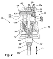
- Fig. 2
- eine zweite Ausführungsform einer erfindungsgemäßen Austragvorrichtung mit einem erfindungsgemäßen Austragkopf.
- Fig. 1
- a first embodiment of a discharge device according to the invention with a discharge head according to the invention and
- Fig. 2
- A second embodiment of a discharge device according to the invention with a discharge head according to the invention.
An das Ausgangsventil 36b schließt sich ein Rohrabschnitt 38b an, der einen ersten Abschnitt 40a eines Zufuhrpfades 40 definiert. Auf den Rohrabschnitt 38b ist ein austragkopfseitiger Rohrabschnitt 52a aufgepresst, der einen Teil eines in etwa L-förmigen zweiten Abschnitts 40b des Zufuhrpfades 40 begrenzt. An diesen zweiten Abschnitt 40b des Zufuhrpfades 40 schließen sich eine Druckkammer 40c sowie eine Austragsöffnung 54 an.The
Der Rohrabschnitt 52a ist Teil des Austragkopfes 50. Durch die Verbindung des Rohrabschnitts 52a mit dem Rohrabschnitt 38b wird gleichzeitig auch der Austragkopf 50 mit dem Pumpenaufsatz 30 verbunden.The
In einem sich quer zu einer Haupterstreckungsrichtung 2 erstreckenden Teil des zweiten Abschnitt 40b des Zufuhrpfades 40 sowie in der Druckkammer 40c ist ein Ventilschieber 60 vorgesehen, der über einen schaftförmigen Abschnitt 62 und einen sich an den schaftförmigen Abschnitt 62 radial anschließenden Ventilteller 64 verfügt.In a transverse to a
Der Schaft 62 ist innerhalb des zweiten Abschnitts 40b angeordnet. Er weist ein konisch geformtes Ende 62a auf, welches im dargestellten Schließzustand die Austragöffnung 54 dicht verschließt. Diese Ausgestaltung des konischen Endes 62a und der Austragöffnung 54 stellt einen zuverlässigen Schutz gegen mikrobiologische Verunreinigungen dar.The
Der Ventilteller 64 ist innerhalb der Druckkammer 40c angeordnet und trennt diese von einem angrenzenden Federaufnahmeraum 56. Der Außendurchmesser des Ventiltellers 64 ist auf den Innendurchmesser der Druckkammer 40c angepasst, so dass keine Flüssigkeit aus der Druckkammer 40c in den Federaufnahmeraum 56 gelangen kann. Im Federaufnahmeraum ist eine Feder 58 angeordnet, die sich am Gehäuse des Austragkopfes 50 abstützt, den Ventilschieber 60 mit einer Federkraft in Richtung der Austragöffnung 54 kraftbeaufschlagt und dadurch den Schließzustand herstellt.The
Die Funktionsweise der Austragvorrichtung nach abgeschlossener Inbetriebnahme wird nachfolgend erläutert.The operation of the discharge after completion of commissioning will be explained below.
Eine Betätigung der Austragvorrichtung erfolgt durch einen in Haupterstreckungsrichtung 2 wirkenden Betätigungshub durch eine auf eine Fingerauflage 50a des Austragkopfes 50 aufgebrachte Betätigungskraft entgegen der Rückstellkraft der Rückstellfeder 12. Hierdurch wird der Austragkopf 50 in seiner Gesamtheit gemeinsam mit dem Zufuhrpfad 40 in Richtung des Pumpenabschnitts 30 verschoben. Dies führt zu einem Verschließen des Eingangsventils 36a und einem Öffnen des Ausgangsventils 36b. Die in der Pumpkammer 34 zu diesem Zeitpunkt vorhandene Flüssigkeit wird dadurch in den ebenfalls schon flüssigkeitsbefüllten Zufuhrpfad 40 gefördert. Dies führt durch die Inkompressibilität der Flüssigkeit bestimmungsgemäß unmittelbar zu einer deutlichen Druckerhöhung im Gesamtsystem aus Pumpkammer 34 und Zufuhrpfad 40 der zu einer Verschiebung des Ventilschiebers 60 entgegen der Federkraft der Feder 58 führt. Hierdurch wird die Austragsöffnung 54 geöffnet und das unter Druck stehende Medium aus dem Zufuhrpfad 40 wird ausgetragen, bis der Flüssigkeitsdruck im Zufuhrpfad wieder unter den Grenzdruck zum Öffnen des Auslassventils gesunken ist. Nach Lösen der Betätigungskraft bringt eine Rückstellfeder 12 den Pumpenabschnitt 30 und den Austragkopf 50 wieder in die Ausgangslage der
Zum Zwecke der Erstinbetriebnahme sowie der Wiederinbetriebnahme nach einem längeren Zeitraum der Nichtnutzung sind im Ventilteller 64 Luftauslassöffnungen 80 vorgesehen, die durch dünnwandige Membranen 82 verschlossen sind. Im Falle der Ausführungsform der
Im Ausgangszustand vor der Erstinbetriebnahme sind der Zufuhrpfad 40 und eventuell die Pumpkammer 34 mit Luft gefüllt. Wenn in diesem Zustand eine Betätigung der Austragvorrichtung erfolgt, wird das Volumen im Gesamtsystem aus Pumpkammer 34 und Zufuhrpfad 40 verringert, so dass der Luftdruck im Zufuhrpfad 40 erhöht wird. Hierdurch wird bewirkt, dass ein Teil der Luft aus dem Zufuhrpfad 40 durch die Membranen 82 nach außen strömt. Nach der Betätigung wird der Austragkopf durch die Rückstellfeder 12 wieder in seine Ausgangsstellung gedrückt, was bei verschlossenem Ausgangsventil 36b eine Vergrößerung des Volumens der Pumpkammer und ein damit verbundenes Einsaugen von Flüssigkeit aus dem Medienspeicher in die Pumpkammer 34 zur Folge hat. Bei diesem Rückhub kommt es nicht zu einem Unterdruck im Zufuhrpfad 40 und damit in der Druckkammer 40c, so dass ein Einziehen von Luft aus der Umgebung in die Druckkammer 40c nicht stattfindet. Bei der nächsten Betätigung wird die Flüssigkeit aus der Pumpkammer 34 in den Zufuhrpfad 40 gedrückt und verdrängt dort wiederum Luft, welche durch die Luftauslässe 80 entweicht. Durch wiederholtes Betätigen wird Schritt für Schritt mehr Flüssigkeit in den Zufuhrpfad 40 gefördert und die Luft durch die Membranen 82 aus dem Zufuhrpfad 40 herausgedrückt. Wenn der Anteil der Flüssigkeit im Zufuhrpfad 40 ausreichend groß und der Druck durch Verdrängung von Luft nicht mehr verminderbar ist, wird im Zuge de Betätigung ein ausreichend hoher Druck im Zufuhrpfad erreicht, um ein Öffnen des Auslassventils durch eine Verschiebung des Ventilschiebers 60 zu erzielen. Dadurch ist der Betriebszustand der Austragvorrichtung erreicht, in dem jede Betätigung zu einem Öffnen des Auslassventils führt.In the initial state before the first commissioning of the
Die Ausführungsform der
Die technische Funktionsweise der Austragvorrichtung der
Claims (10)
dadurch gekennzeichnet, dass
der Luftauslass (80) im Bereich des Zufuhrpfades (40) vorgesehen ist, insbesondere in einem in einer Benutzungsstellung der Austragvorrichtung (10) oberen Bereich.Discharge device according to claim 1,
characterized in that
the air outlet (80) is provided in the area of the feed path (40), in particular in an upper area in a position of use of the discharge device (10).
dadurch gekennzeichnet, dass
der Luftauslass (80) für die Luft und die Austragöffnung (54) für die Flüssigkeit in entgegengesetzte Richtung weisend und orthogonal zu einer Haupterstreckungsrichtung (2) der Austragvorrichtung (10) ausgebildet sind.Discharge device according to claim 1 or 2,
characterized in that
the air outlet (80) for the air and the discharge opening (54) for the liquid are oriented in the opposite direction and orthogonal to a main extension direction (2) of the discharge device (10).
dadurch gekennzeichnet, dass
der Luftauslass (80) in einem Ventilschieber (60) vorgesehen ist, vorzugsweise an einer einem Schließabschnitt (62a) des Ventilschiebers (60) gegenüberliegenden Seite, insbesondere an einem an der gegenüberliegenden Seite vorgesehenen Druckteller (64) des Ventilschiebers (60).Discharge device according to one of the preceding claims,
characterized in that
the air outlet (80) is provided in a valve slide (60), preferably on a side opposite a closing section (62a) of the valve slide (60), in particular on a pressure plate (64) of the valve slide (60) provided on the opposite side.
dadurch gekennzeichnet, dass
der Luftauslass (80) durch eine gasdurchlässige und flüssigkeitsdichte Membran (82) verschlossen ist.Discharge device according to one of the preceding claims,
characterized in that
the air outlet (80) is closed by a gas-permeable and liquid-tight membrane (82).
dadurch gekennzeichnet, dass
die Membran (82) eine mittlere Porengröße zwischen 0,1 µm und 0,5 µm aufweist.Discharge device according to one of the preceding claims,
characterized in that
the membrane (82) has an average pore size between 0.1 μm and 0.5 μm.
dadurch gekennzeichnet, dass
die Membran (82) einstückig in einem Bauteil (60, 64) der Austragvorrichtung ausgebildet ist.Discharge device according to claim 5 or 6,
characterized in that
the membrane (82) is integrally formed in a component (60, 64) of the discharge device.
dadurch gekennzeichnet, dass
der Luftauslass (80) mikrobiologisch dichtend ausgebildet ist.Discharge device according to one of the preceding claims,
characterized in that
the air outlet (80) is microbiologically sealed.
dadurch gekennzeichnet, dass
die Membran (82) aus PTFE oder Polyester besteht und vorzugsweise eine Dicke kleiner 500 µm, vorzugsweise kleiner 350 µm, aufweist.Discharge device according to one of claims 5 to 8,
characterized in that
the membrane (82) consists of PTFE or polyester and preferably has a thickness of less than 500 μm, preferably less than 350 μm.
Applications Claiming Priority (1)
| Application Number | Priority Date | Filing Date | Title |
|---|---|---|---|
| DE102007021415A DE102007021415A1 (en) | 2007-04-30 | 2007-04-30 | discharge |
Publications (3)
| Publication Number | Publication Date |
|---|---|
| EP1987888A2 true EP1987888A2 (en) | 2008-11-05 |
| EP1987888A3 EP1987888A3 (en) | 2010-06-02 |
| EP1987888B1 EP1987888B1 (en) | 2011-05-25 |
Family
ID=39689157
Family Applications (1)
| Application Number | Title | Priority Date | Filing Date |
|---|---|---|---|
| EP08007090A Active EP1987888B1 (en) | 2007-04-30 | 2008-04-10 | Discharge device |
Country Status (5)
| Country | Link |
|---|---|
| US (1) | US8038036B2 (en) |
| EP (1) | EP1987888B1 (en) |
| AT (1) | ATE510628T1 (en) |
| DE (1) | DE102007021415A1 (en) |
| ES (1) | ES2364786T3 (en) |
Cited By (1)
| Publication number | Priority date | Publication date | Assignee | Title |
|---|---|---|---|---|
| EP3243571A1 (en) * | 2016-05-10 | 2017-11-15 | Zhejiang JM Industry Co., Ltd | Fluid pump |
Families Citing this family (9)
| Publication number | Priority date | Publication date | Assignee | Title |
|---|---|---|---|---|
| EP2342990A4 (en) * | 2008-10-20 | 2013-09-18 | Jae-Sam Byeon | Airless type cosmetic container |
| US8888978B2 (en) * | 2011-03-11 | 2014-11-18 | Life Safety Distribution Ag | Vented oxygen cell |
| DE202011000682U1 (en) * | 2011-03-24 | 2013-11-12 | Rpc Bramlage Gmbh | Dispenser for dispensing liquid to pasty masses |
| DE102013113791A1 (en) * | 2013-12-10 | 2015-06-11 | Rpc Bramlage Gmbh | donor |
| EP3103498B2 (en) | 2015-06-12 | 2023-06-14 | AP Pharma Systems Atomizadores e Dispensadores Ltda | Spray dispenser for nasal drugs |
| US9981278B2 (en) | 2016-05-10 | 2018-05-29 | Zhejiang Jm Industry Co., Ltd. | Extended emission time liquid sprayer |
| US9943867B2 (en) | 2016-05-10 | 2018-04-17 | Zhejiang JM Industry Co., Ltd | Extended emission time liquid sprayer |
| FR3072311A1 (en) * | 2017-10-12 | 2019-04-19 | Promens Sa | DEVICE FOR DISPENSING PAST LIQUID PRODUCTS WITH CLOSURE DEVICE FORMING A MODULE |
| DE102019110454A1 (en) * | 2018-04-24 | 2019-10-24 | Gerhard Brugger | Dispensers |
Family Cites Families (18)
| Publication number | Priority date | Publication date | Assignee | Title |
|---|---|---|---|---|
| FR2149669A5 (en) * | 1971-08-19 | 1973-03-30 | Step | |
| US4533068A (en) * | 1981-08-17 | 1985-08-06 | Health Care Concepts, Inc. | Sterile solution delivery and venting devices |
| DE3315334A1 (en) * | 1983-04-28 | 1984-10-31 | Pfeiffer Erich Gmbh & Co Kg | SPRAYER OR DOSING PUMP |
| US5242406A (en) | 1990-10-19 | 1993-09-07 | Sil Medics Ltd. | Liquid delivery device particularly useful for delivering drugs |
| US5238153A (en) * | 1991-02-19 | 1993-08-24 | Pilkington Visioncare Inc. | Dispenser for dispersing sterile solutions |
| US5429275A (en) * | 1991-07-02 | 1995-07-04 | Katz; Otto | Dispenser of doses of liquids and paste-like masses |
| US5197638A (en) * | 1991-10-30 | 1993-03-30 | Allergan, Inc. | Self sealing product delivery system |
| IT1270138B (en) * | 1994-05-25 | 1997-04-29 | Giovanni Albini | NEBULIZED PRESSURE FLUID DISPENSER, PROVIDED WITH MOBILE SHUTTER FOR PRESSURE FLUID ACTION |
| FR2723618B1 (en) * | 1994-08-11 | 1996-10-31 | Sofab | MEMBRANE PUMP |
| JP2892289B2 (en) * | 1994-09-16 | 1999-05-17 | キャニヨン株式会社 | Trigger-type dispenser and one-way valve therefor |
| CA2179888C (en) | 1994-10-26 | 2007-08-28 | Tadao Saito | Trigger type liquid discharge device |
| CA2184849A1 (en) * | 1995-09-27 | 1997-03-28 | Donald D. Foster | Liquid dispenser with trigger sprayer |
| US5752629A (en) * | 1996-04-12 | 1998-05-19 | The Procter & Gamble Company | Passive venting for pump dispensing device |
| US5842616A (en) * | 1996-04-24 | 1998-12-01 | Ter S.R.L. | Atomized liquid dispenser applicable to manually operated pumps |
| EP1404609B1 (en) * | 2001-05-23 | 2011-08-31 | Cohen, Ben Z. | Accurate dosing pump |
| DE102004050679A1 (en) | 2004-10-13 | 2006-04-20 | Ing. Erich Pfeiffer Gmbh | metering |
| FR2886926B1 (en) * | 2005-06-10 | 2007-08-31 | Rexam Dispensing Systems Sas | AIR FILTRATION DEVICE FOR LIQUID OR SEMI-LIQUID PRODUCT PUMP |
| FR2907518A1 (en) | 2006-10-20 | 2008-04-25 | Rexam Dispensing Systems Sas | PUMP COMPRISING AIR EXHAUST MEANS |
-
2007
- 2007-04-30 DE DE102007021415A patent/DE102007021415A1/en not_active Withdrawn
-
2008
- 2008-04-10 EP EP08007090A patent/EP1987888B1/en active Active
- 2008-04-10 AT AT08007090T patent/ATE510628T1/en active
- 2008-04-10 ES ES08007090T patent/ES2364786T3/en active Active
- 2008-04-29 US US12/150,559 patent/US8038036B2/en active Active
Non-Patent Citations (1)
| Title |
|---|
| None |
Cited By (2)
| Publication number | Priority date | Publication date | Assignee | Title |
|---|---|---|---|---|
| EP3243571A1 (en) * | 2016-05-10 | 2017-11-15 | Zhejiang JM Industry Co., Ltd | Fluid pump |
| JP2017202875A (en) * | 2016-05-10 | 2017-11-16 | ゼージアン ジェイエム インダストリー カンパニー、リミテッド | Fluid pump |
Also Published As
| Publication number | Publication date |
|---|---|
| ES2364786T3 (en) | 2011-09-14 |
| EP1987888A3 (en) | 2010-06-02 |
| US8038036B2 (en) | 2011-10-18 |
| DE102007021415A1 (en) | 2008-11-06 |
| US20080264975A1 (en) | 2008-10-30 |
| EP1987888B1 (en) | 2011-05-25 |
| ATE510628T1 (en) | 2011-06-15 |
Similar Documents
| Publication | Publication Date | Title |
|---|---|---|
| EP1987888B1 (en) | Discharge device | |
| EP0815946B1 (en) | Dispenser for products | |
| EP2130610B2 (en) | Discharge device | |
| DE69820189T2 (en) | System and method for spray or aerosol tip with one-way flow | |
| EP3094416B1 (en) | Dispenser for liquids | |
| EP1834704A2 (en) | Discharge device for a flowable medium | |
| EP2753433B1 (en) | Liquid dispenser | |
| DE102013211423A1 (en) | Multilayer container | |
| EP1588772B1 (en) | Dosing pump and method for manufacturing the same | |
| EP3427840B1 (en) | Liquid dispenser | |
| DE102010048085A1 (en) | discharge | |
| EP2314380A2 (en) | Dispenser | |
| EP2634112A1 (en) | Refillable dispensing container | |
| EP3380211A1 (en) | Filter cartridge for an oil filter of a motor vehicle, and oil filter | |
| EP3978389A1 (en) | Liquid dispenser, in particular drop dispenser | |
| EP0451615B1 (en) | Discharge device for at least one medium | |
| EP2654967B1 (en) | Liquid dispenser | |
| DE202007011587U1 (en) | Directional valve for a windscreen cleaning device in a motor vehicle | |
| DE102013205895A1 (en) | Pulverdichtstrompumpe for conveying coating powder and corresponding method | |
| EP2246122B1 (en) | Application device for liquid or paste media | |
| EP3736049A1 (en) | Discharge head and liquid dispenser with a discharge head | |
| DE102008052589A1 (en) | Fluid discharge device for use in air freshener device of air conditioning system of motor vehicle, has controlled valve devices actuated by common actuation device, where controlled valve devices are formed as valve device | |
| EP3821987B1 (en) | Fluid dispenser with bottle ventilation | |
| DE102009048551A1 (en) | Discharge device and assembly method for this | |
| DE102017213908A1 (en) | Storage and fluid material discharge system |
Legal Events
| Date | Code | Title | Description |
|---|---|---|---|
| PUAI | Public reference made under article 153(3) epc to a published international application that has entered the european phase |
Free format text: ORIGINAL CODE: 0009012 |
|
| AK | Designated contracting states |
Kind code of ref document: A2 Designated state(s): AT BE BG CH CY CZ DE DK EE ES FI FR GB GR HR HU IE IS IT LI LT LU LV MC MT NL NO PL PT RO SE SI SK TR |
|
| AX | Request for extension of the european patent |
Extension state: AL BA MK RS |
|
| PUAL | Search report despatched |
Free format text: ORIGINAL CODE: 0009013 |
|
| AK | Designated contracting states |
Kind code of ref document: A3 Designated state(s): AT BE BG CH CY CZ DE DK EE ES FI FR GB GR HR HU IE IS IT LI LT LU LV MC MT NL NO PL PT RO SE SI SK TR |
|
| AX | Request for extension of the european patent |
Extension state: AL BA MK RS |
|
| 17P | Request for examination filed |
Effective date: 20100906 |
|
| RIC1 | Information provided on ipc code assigned before grant |
Ipc: B05B 11/00 20060101AFI20101005BHEP |
|
| GRAP | Despatch of communication of intention to grant a patent |
Free format text: ORIGINAL CODE: EPIDOSNIGR1 |
|
| AKX | Designation fees paid |
Designated state(s): AT BE BG CH CY CZ DE DK EE ES FI FR GB GR HR HU IE IS IT LI LT LU LV MC MT NL NO PL PT RO SE SI SK TR |
|
| GRAS | Grant fee paid |
Free format text: ORIGINAL CODE: EPIDOSNIGR3 |
|
| GRAA | (expected) grant |
Free format text: ORIGINAL CODE: 0009210 |
|
| AK | Designated contracting states |
Kind code of ref document: B1 Designated state(s): AT BE BG CH CY CZ DE DK EE ES FI FR GB GR HR HU IE IS IT LI LT LU LV MC MT NL NO PL PT RO SE SI SK TR |
|
| REG | Reference to a national code |
Ref country code: GB Ref legal event code: FG4D Free format text: NOT ENGLISH |
|
| REG | Reference to a national code |
Ref country code: CH Ref legal event code: EP |
|
| REG | Reference to a national code |
Ref country code: IE Ref legal event code: FG4D Free format text: LANGUAGE OF EP DOCUMENT: GERMAN |
|
| REG | Reference to a national code |
Ref country code: DE Ref legal event code: R096 Ref document number: 502008003647 Country of ref document: DE Effective date: 20110707 |
|
| REG | Reference to a national code |
Ref country code: CH Ref legal event code: NV Representative=s name: ZIMMERLI, WAGNER & PARTNER AG |
|
| REG | Reference to a national code |
Ref country code: ES Ref legal event code: FG2A Ref document number: 2364786 Country of ref document: ES Kind code of ref document: T3 Effective date: 20110914 |
|
| REG | Reference to a national code |
Ref country code: NL Ref legal event code: VDEP Effective date: 20110525 |
|
| PG25 | Lapsed in a contracting state [announced via postgrant information from national office to epo] |
Ref country code: NO Free format text: LAPSE BECAUSE OF FAILURE TO SUBMIT A TRANSLATION OF THE DESCRIPTION OR TO PAY THE FEE WITHIN THE PRESCRIBED TIME-LIMIT Effective date: 20110825 Ref country code: PT Free format text: LAPSE BECAUSE OF FAILURE TO SUBMIT A TRANSLATION OF THE DESCRIPTION OR TO PAY THE FEE WITHIN THE PRESCRIBED TIME-LIMIT Effective date: 20110926 Ref country code: SE Free format text: LAPSE BECAUSE OF FAILURE TO SUBMIT A TRANSLATION OF THE DESCRIPTION OR TO PAY THE FEE WITHIN THE PRESCRIBED TIME-LIMIT Effective date: 20110525 Ref country code: HR Free format text: LAPSE BECAUSE OF FAILURE TO SUBMIT A TRANSLATION OF THE DESCRIPTION OR TO PAY THE FEE WITHIN THE PRESCRIBED TIME-LIMIT Effective date: 20110525 Ref country code: LT Free format text: LAPSE BECAUSE OF FAILURE TO SUBMIT A TRANSLATION OF THE DESCRIPTION OR TO PAY THE FEE WITHIN THE PRESCRIBED TIME-LIMIT Effective date: 20110525 |
|
| PG25 | Lapsed in a contracting state [announced via postgrant information from national office to epo] |
Ref country code: CY Free format text: LAPSE BECAUSE OF FAILURE TO SUBMIT A TRANSLATION OF THE DESCRIPTION OR TO PAY THE FEE WITHIN THE PRESCRIBED TIME-LIMIT Effective date: 20110525 Ref country code: LV Free format text: LAPSE BECAUSE OF FAILURE TO SUBMIT A TRANSLATION OF THE DESCRIPTION OR TO PAY THE FEE WITHIN THE PRESCRIBED TIME-LIMIT Effective date: 20110525 Ref country code: FI Free format text: LAPSE BECAUSE OF FAILURE TO SUBMIT A TRANSLATION OF THE DESCRIPTION OR TO PAY THE FEE WITHIN THE PRESCRIBED TIME-LIMIT Effective date: 20110525 Ref country code: SI Free format text: LAPSE BECAUSE OF FAILURE TO SUBMIT A TRANSLATION OF THE DESCRIPTION OR TO PAY THE FEE WITHIN THE PRESCRIBED TIME-LIMIT Effective date: 20110525 Ref country code: GR Free format text: LAPSE BECAUSE OF FAILURE TO SUBMIT A TRANSLATION OF THE DESCRIPTION OR TO PAY THE FEE WITHIN THE PRESCRIBED TIME-LIMIT Effective date: 20110826 Ref country code: IS Free format text: LAPSE BECAUSE OF FAILURE TO SUBMIT A TRANSLATION OF THE DESCRIPTION OR TO PAY THE FEE WITHIN THE PRESCRIBED TIME-LIMIT Effective date: 20110925 |
|
| REG | Reference to a national code |
Ref country code: IE Ref legal event code: FD4D |
|
| PG25 | Lapsed in a contracting state [announced via postgrant information from national office to epo] |
Ref country code: NL Free format text: LAPSE BECAUSE OF FAILURE TO SUBMIT A TRANSLATION OF THE DESCRIPTION OR TO PAY THE FEE WITHIN THE PRESCRIBED TIME-LIMIT Effective date: 20110525 |
|
| PG25 | Lapsed in a contracting state [announced via postgrant information from national office to epo] |
Ref country code: IE Free format text: LAPSE BECAUSE OF FAILURE TO SUBMIT A TRANSLATION OF THE DESCRIPTION OR TO PAY THE FEE WITHIN THE PRESCRIBED TIME-LIMIT Effective date: 20110525 Ref country code: CZ Free format text: LAPSE BECAUSE OF FAILURE TO SUBMIT A TRANSLATION OF THE DESCRIPTION OR TO PAY THE FEE WITHIN THE PRESCRIBED TIME-LIMIT Effective date: 20110525 Ref country code: EE Free format text: LAPSE BECAUSE OF FAILURE TO SUBMIT A TRANSLATION OF THE DESCRIPTION OR TO PAY THE FEE WITHIN THE PRESCRIBED TIME-LIMIT Effective date: 20110525 |
|
| PG25 | Lapsed in a contracting state [announced via postgrant information from national office to epo] |
Ref country code: RO Free format text: LAPSE BECAUSE OF FAILURE TO SUBMIT A TRANSLATION OF THE DESCRIPTION OR TO PAY THE FEE WITHIN THE PRESCRIBED TIME-LIMIT Effective date: 20110525 Ref country code: SK Free format text: LAPSE BECAUSE OF FAILURE TO SUBMIT A TRANSLATION OF THE DESCRIPTION OR TO PAY THE FEE WITHIN THE PRESCRIBED TIME-LIMIT Effective date: 20110525 Ref country code: PL Free format text: LAPSE BECAUSE OF FAILURE TO SUBMIT A TRANSLATION OF THE DESCRIPTION OR TO PAY THE FEE WITHIN THE PRESCRIBED TIME-LIMIT Effective date: 20110525 Ref country code: DK Free format text: LAPSE BECAUSE OF FAILURE TO SUBMIT A TRANSLATION OF THE DESCRIPTION OR TO PAY THE FEE WITHIN THE PRESCRIBED TIME-LIMIT Effective date: 20110525 |
|
| PLBE | No opposition filed within time limit |
Free format text: ORIGINAL CODE: 0009261 |
|
| STAA | Information on the status of an ep patent application or granted ep patent |
Free format text: STATUS: NO OPPOSITION FILED WITHIN TIME LIMIT |
|
| 26N | No opposition filed |
Effective date: 20120228 |
|
| REG | Reference to a national code |
Ref country code: DE Ref legal event code: R097 Ref document number: 502008003647 Country of ref document: DE Effective date: 20120228 |
|
| BERE | Be: lapsed |
Owner name: ING. ERICH PFEIFFER G.M.B.H. Effective date: 20120430 |
|
| PG25 | Lapsed in a contracting state [announced via postgrant information from national office to epo] |
Ref country code: MC Free format text: LAPSE BECAUSE OF NON-PAYMENT OF DUE FEES Effective date: 20120430 |
|
| REG | Reference to a national code |
Ref country code: DE Ref legal event code: R082 Ref document number: 502008003647 Country of ref document: DE Representative=s name: PATENTANWAELTE RUFF, WILHELM, BEIER, DAUSTER &, DE Effective date: 20121025 Ref country code: DE Ref legal event code: R081 Ref document number: 502008003647 Country of ref document: DE Owner name: APTAR RADOLFZELL GMBH, DE Free format text: FORMER OWNER: ING. ERICH PFEIFFER GMBH, 78315 RADOLFZELL, DE Effective date: 20121025 Ref country code: DE Ref legal event code: R082 Ref document number: 502008003647 Country of ref document: DE Representative=s name: PATENTANWALTSKANZLEI CARTAGENA PARTNERSCHAFTSG, DE Effective date: 20121025 |
|
| PG25 | Lapsed in a contracting state [announced via postgrant information from national office to epo] |
Ref country code: BE Free format text: LAPSE BECAUSE OF NON-PAYMENT OF DUE FEES Effective date: 20120430 |
|
| PG25 | Lapsed in a contracting state [announced via postgrant information from national office to epo] |
Ref country code: BG Free format text: LAPSE BECAUSE OF FAILURE TO SUBMIT A TRANSLATION OF THE DESCRIPTION OR TO PAY THE FEE WITHIN THE PRESCRIBED TIME-LIMIT Effective date: 20110825 |
|
| PG25 | Lapsed in a contracting state [announced via postgrant information from national office to epo] |
Ref country code: MT Free format text: LAPSE BECAUSE OF FAILURE TO SUBMIT A TRANSLATION OF THE DESCRIPTION OR TO PAY THE FEE WITHIN THE PRESCRIBED TIME-LIMIT Effective date: 20110525 |
|
| REG | Reference to a national code |
Ref country code: CH Ref legal event code: NV Representative=s name: WAGNER PATENT AG, CH |
|
| PG25 | Lapsed in a contracting state [announced via postgrant information from national office to epo] |
Ref country code: TR Free format text: LAPSE BECAUSE OF FAILURE TO SUBMIT A TRANSLATION OF THE DESCRIPTION OR TO PAY THE FEE WITHIN THE PRESCRIBED TIME-LIMIT Effective date: 20110525 |
|
| PG25 | Lapsed in a contracting state [announced via postgrant information from national office to epo] |
Ref country code: LU Free format text: LAPSE BECAUSE OF NON-PAYMENT OF DUE FEES Effective date: 20120410 |
|
| REG | Reference to a national code |
Ref country code: AT Ref legal event code: MM01 Ref document number: 510628 Country of ref document: AT Kind code of ref document: T Effective date: 20130410 |
|
| PG25 | Lapsed in a contracting state [announced via postgrant information from national office to epo] |
Ref country code: HU Free format text: LAPSE BECAUSE OF FAILURE TO SUBMIT A TRANSLATION OF THE DESCRIPTION OR TO PAY THE FEE WITHIN THE PRESCRIBED TIME-LIMIT Effective date: 20080410 |
|
| PG25 | Lapsed in a contracting state [announced via postgrant information from national office to epo] |
Ref country code: AT Free format text: LAPSE BECAUSE OF NON-PAYMENT OF DUE FEES Effective date: 20130410 |
|
| REG | Reference to a national code |
Ref country code: DE Ref legal event code: R082 Ref document number: 502008003647 Country of ref document: DE Representative=s name: WITTE, WELLER & PARTNER PATENTANWAELTE MBB, DE Ref country code: DE Ref legal event code: R082 Ref document number: 502008003647 Country of ref document: DE Representative=s name: PATENTANWALTSKANZLEI CARTAGENA PARTNERSCHAFTSG, DE |
|
| REG | Reference to a national code |
Ref country code: FR Ref legal event code: PLFP Year of fee payment: 9 |
|
| REG | Reference to a national code |
Ref country code: FR Ref legal event code: PLFP Year of fee payment: 10 |
|
| REG | Reference to a national code |
Ref country code: FR Ref legal event code: PLFP Year of fee payment: 11 |
|
| PGFP | Annual fee paid to national office [announced via postgrant information from national office to epo] |
Ref country code: ES Payment date: 20210519 Year of fee payment: 14 Ref country code: CH Payment date: 20210422 Year of fee payment: 14 Ref country code: GB Payment date: 20210422 Year of fee payment: 14 |
|
| REG | Reference to a national code |
Ref country code: DE Ref legal event code: R082 Ref document number: 502008003647 Country of ref document: DE Representative=s name: WITTE, WELLER & PARTNER PATENTANWAELTE MBB, DE |
|
| REG | Reference to a national code |
Ref country code: CH Ref legal event code: PL |
|
| GBPC | Gb: european patent ceased through non-payment of renewal fee |
Effective date: 20220410 |
|
| PG25 | Lapsed in a contracting state [announced via postgrant information from national office to epo] |
Ref country code: LI Free format text: LAPSE BECAUSE OF NON-PAYMENT OF DUE FEES Effective date: 20220430 Ref country code: GB Free format text: LAPSE BECAUSE OF NON-PAYMENT OF DUE FEES Effective date: 20220410 Ref country code: CH Free format text: LAPSE BECAUSE OF NON-PAYMENT OF DUE FEES Effective date: 20220430 |
|
| REG | Reference to a national code |
Ref country code: FR Ref legal event code: PLFP Year of fee payment: 16 |
|
| REG | Reference to a national code |
Ref country code: ES Ref legal event code: FD2A Effective date: 20230526 |
|
| P01 | Opt-out of the competence of the unified patent court (upc) registered |
Effective date: 20230502 |
|
| PG25 | Lapsed in a contracting state [announced via postgrant information from national office to epo] |
Ref country code: ES Free format text: LAPSE BECAUSE OF NON-PAYMENT OF DUE FEES Effective date: 20220411 |
|
| PGFP | Annual fee paid to national office [announced via postgrant information from national office to epo] |
Ref country code: IT Payment date: 20230428 Year of fee payment: 16 Ref country code: FR Payment date: 20230413 Year of fee payment: 16 Ref country code: DE Payment date: 20230421 Year of fee payment: 16 |