EP1987129B1 - Fermentation device comprising a coupled substrate and sediment transport mechanism and method for operating the fermentation device - Google Patents
Fermentation device comprising a coupled substrate and sediment transport mechanism and method for operating the fermentation device Download PDFInfo
- Publication number
- EP1987129B1 EP1987129B1 EP20060829215 EP06829215A EP1987129B1 EP 1987129 B1 EP1987129 B1 EP 1987129B1 EP 20060829215 EP20060829215 EP 20060829215 EP 06829215 A EP06829215 A EP 06829215A EP 1987129 B1 EP1987129 B1 EP 1987129B1
- Authority
- EP
- European Patent Office
- Prior art keywords
- container
- fermentation device
- substrate
- stirring
- stirring blades
- Prior art date
- Legal status (The legal status is an assumption and is not a legal conclusion. Google has not performed a legal analysis and makes no representation as to the accuracy of the status listed.)
- Active
Links
- 238000000855 fermentation Methods 0.000 title claims description 37
- 230000004151 fermentation Effects 0.000 title claims description 37
- 239000000758 substrate Substances 0.000 title claims description 24
- 239000013049 sediment Substances 0.000 title claims description 20
- 238000000034 method Methods 0.000 title claims description 10
- 230000007723 transport mechanism Effects 0.000 title 1
- 238000003756 stirring Methods 0.000 claims description 32
- 238000006243 chemical reaction Methods 0.000 claims description 7
- 239000011368 organic material Substances 0.000 claims description 5
- 238000006065 biodegradation reaction Methods 0.000 claims description 4
- 230000015556 catabolic process Effects 0.000 claims description 4
- 238000006731 degradation reaction Methods 0.000 claims description 4
- 238000002156 mixing Methods 0.000 claims description 4
- 239000007857 degradation product Substances 0.000 claims description 2
- 230000007246 mechanism Effects 0.000 claims 1
- 239000007787 solid Substances 0.000 description 7
- 239000000463 material Substances 0.000 description 5
- 239000007788 liquid Substances 0.000 description 4
- 230000015572 biosynthetic process Effects 0.000 description 3
- 239000012535 impurity Substances 0.000 description 3
- XLYOFNOQVPJJNP-UHFFFAOYSA-N water Substances O XLYOFNOQVPJJNP-UHFFFAOYSA-N 0.000 description 3
- 238000007872 degassing Methods 0.000 description 2
- 230000000694 effects Effects 0.000 description 2
- 210000003608 fece Anatomy 0.000 description 2
- 238000007667 floating Methods 0.000 description 2
- 239000010871 livestock manure Substances 0.000 description 2
- 239000002994 raw material Substances 0.000 description 2
- 239000002699 waste material Substances 0.000 description 2
- 230000003750 conditioning effect Effects 0.000 description 1
- 238000010276 construction Methods 0.000 description 1
- 238000013461 design Methods 0.000 description 1
- 238000011161 development Methods 0.000 description 1
- 238000010790 dilution Methods 0.000 description 1
- 239000012895 dilution Substances 0.000 description 1
- 238000006073 displacement reaction Methods 0.000 description 1
- 239000003337 fertilizer Substances 0.000 description 1
- 230000009969 flowable effect Effects 0.000 description 1
- 239000011521 glass Substances 0.000 description 1
- 238000000265 homogenisation Methods 0.000 description 1
- 238000012423 maintenance Methods 0.000 description 1
- 238000004519 manufacturing process Methods 0.000 description 1
- 150000002894 organic compounds Chemical class 0.000 description 1
- 239000004033 plastic Substances 0.000 description 1
- 238000011084 recovery Methods 0.000 description 1
- 239000004576 sand Substances 0.000 description 1
- 238000005204 segregation Methods 0.000 description 1
- 239000000243 solution Substances 0.000 description 1
- 238000000638 solvent extraction Methods 0.000 description 1
- 239000004575 stone Substances 0.000 description 1
- 239000000126 substance Substances 0.000 description 1
- 239000000725 suspension Substances 0.000 description 1
- 238000012546 transfer Methods 0.000 description 1
- 238000013024 troubleshooting Methods 0.000 description 1
- 239000002023 wood Substances 0.000 description 1
Images
Classifications
-
- C—CHEMISTRY; METALLURGY
- C12—BIOCHEMISTRY; BEER; SPIRITS; WINE; VINEGAR; MICROBIOLOGY; ENZYMOLOGY; MUTATION OR GENETIC ENGINEERING
- C12M—APPARATUS FOR ENZYMOLOGY OR MICROBIOLOGY; APPARATUS FOR CULTURING MICROORGANISMS FOR PRODUCING BIOMASS, FOR GROWING CELLS OR FOR OBTAINING FERMENTATION OR METABOLIC PRODUCTS, i.e. BIOREACTORS OR FERMENTERS
- C12M29/00—Means for introduction, extraction or recirculation of materials, e.g. pumps
- C12M29/18—External loop; Means for reintroduction of fermented biomass or liquid percolate
-
- C—CHEMISTRY; METALLURGY
- C12—BIOCHEMISTRY; BEER; SPIRITS; WINE; VINEGAR; MICROBIOLOGY; ENZYMOLOGY; MUTATION OR GENETIC ENGINEERING
- C12M—APPARATUS FOR ENZYMOLOGY OR MICROBIOLOGY; APPARATUS FOR CULTURING MICROORGANISMS FOR PRODUCING BIOMASS, FOR GROWING CELLS OR FOR OBTAINING FERMENTATION OR METABOLIC PRODUCTS, i.e. BIOREACTORS OR FERMENTERS
- C12M21/00—Bioreactors or fermenters specially adapted for specific uses
- C12M21/04—Bioreactors or fermenters specially adapted for specific uses for producing gas, e.g. biogas
-
- C—CHEMISTRY; METALLURGY
- C12—BIOCHEMISTRY; BEER; SPIRITS; WINE; VINEGAR; MICROBIOLOGY; ENZYMOLOGY; MUTATION OR GENETIC ENGINEERING
- C12M—APPARATUS FOR ENZYMOLOGY OR MICROBIOLOGY; APPARATUS FOR CULTURING MICROORGANISMS FOR PRODUCING BIOMASS, FOR GROWING CELLS OR FOR OBTAINING FERMENTATION OR METABOLIC PRODUCTS, i.e. BIOREACTORS OR FERMENTERS
- C12M27/00—Means for mixing, agitating or circulating fluids in the vessel
- C12M27/02—Stirrer or mobile mixing elements
- C12M27/06—Stirrer or mobile mixing elements with horizontal or inclined stirrer shaft or axis
-
- Y—GENERAL TAGGING OF NEW TECHNOLOGICAL DEVELOPMENTS; GENERAL TAGGING OF CROSS-SECTIONAL TECHNOLOGIES SPANNING OVER SEVERAL SECTIONS OF THE IPC; TECHNICAL SUBJECTS COVERED BY FORMER USPC CROSS-REFERENCE ART COLLECTIONS [XRACs] AND DIGESTS
- Y02—TECHNOLOGIES OR APPLICATIONS FOR MITIGATION OR ADAPTATION AGAINST CLIMATE CHANGE
- Y02E—REDUCTION OF GREENHOUSE GAS [GHG] EMISSIONS, RELATED TO ENERGY GENERATION, TRANSMISSION OR DISTRIBUTION
- Y02E50/00—Technologies for the production of fuel of non-fossil origin
- Y02E50/30—Fuel from waste, e.g. synthetic alcohol or diesel
-
- Y—GENERAL TAGGING OF NEW TECHNOLOGICAL DEVELOPMENTS; GENERAL TAGGING OF CROSS-SECTIONAL TECHNOLOGIES SPANNING OVER SEVERAL SECTIONS OF THE IPC; TECHNICAL SUBJECTS COVERED BY FORMER USPC CROSS-REFERENCE ART COLLECTIONS [XRACs] AND DIGESTS
- Y02—TECHNOLOGIES OR APPLICATIONS FOR MITIGATION OR ADAPTATION AGAINST CLIMATE CHANGE
- Y02W—CLIMATE CHANGE MITIGATION TECHNOLOGIES RELATED TO WASTEWATER TREATMENT OR WASTE MANAGEMENT
- Y02W30/00—Technologies for solid waste management
- Y02W30/40—Bio-organic fraction processing; Production of fertilisers from the organic fraction of waste or refuse
Definitions
- the invention relates to a fermentation device for the biodegradation of organic material containing substrate and recovery of biogas formed during degradation with an elongated closed container having a frontal introduction opening for the substrate and a discharge opening for treated substrate at the opposite end of the container and at least one vent for biogas wherein the container comprises a plurality of reaction volume cells, each containing a plurality of individually driven agitating means with circularly moving stirring blades and transverse to the longitudinal extent of the container lying agitator shafts for mixing the substrate, and a method for operating the fermentation device.
- a flowable suspension is prepared from the substrate which is stored in a biogas reactor, e.g. a loop reactor with internal loop flow, the substrate is subjected to dry fermentation, e.g. introduced at one end in a closed-lying container, circulated by means of a stirring device with biogas formation and the treated substrate at the other end withdrawn from the container.
- a biogas reactor e.g. a loop reactor with internal loop flow
- dry fermentation e.g. introduced at one end in a closed-lying container, circulated by means of a stirring device with biogas formation and the treated substrate at the other end withdrawn from the container.
- Dry fermentations are used as an alternative to those of wet fermentation, when the anaerobically treated substrate is very rich in solids and therefore the necessary dilution is uneconomical up to the operating range of the wet process with their solids concentrations of less than about 15%, or if the often necessary, but costly Störstoffentfrachtung wet process for other procedural reasons is not required. Dry fermentations are preferred at solids contents of equal to or less than 35% in water Run fermenter entry and can be designed as a standing or horizontal reactors.
- An advantage of dry fermentation when used in waste and residual waste treatment is the comparatively low treatment and conditioning effort for the assumed input materials before fermentation. After a depletion of coarse impurities and subsequent comminution of the fraction for fermentation to 20 to 60 mm is usually before metering into the fermentation reactor no further Störententfrachtung for example. Wood, plastic, glass as well as sand and stones necessary.
- the solids concentrations of about 35% dry substandard to less than 20% dry matter and the viscosity of. are reduced between the feed opening and the discharge opening 30,000 to 60,000 mPas to less than 5,000 mPas.
- Goods in the high-solids use the above sedimentable and floatable impurities largely stable distributed, they are mobilized by the changing material properties of the fermentation medium in the fermenter, which tends to lead to the formation of sinking and floating layers.
- the present invention has for its object to provide a fermentation device of the type mentioned and a method for operating the fermentation device so that in addition to the actual homogenization and degassing of the agitators without affecting the Pfropfenstrom characterizing for the flow of solids between fermenter inlet and outlet at the same time a sediment movement Fermenterende induced and the formation of solidified floating blankets is suppressed.
- stirrer shafts are arranged with axial spacings which are smaller than the stirrer diameter, so that the stirring vanes cover an overlapping region when the stirrer shafts are rotated.
- the invention is based on the prior art, as in the EP 0 617 120 B1 is described.
- This known fermentation device has separately controllable, transverse agitator units which disassemble the fermenter into a series of fictitious reaction volume cells (stirring cells) connected in series.
- the paddle wheel-like beam agitators effect vertical media exchange in their respective agitating cell, including float-deck partitioning by the stirring bars emerging from the liquid, while the horizontal plug flow is generated by the combination of digestate removal and substrate dosing.
- the sediment transport takes place separately by means of a push frame.
- the agitator shafts are arranged in the fermenter in the fermenter in such a way that the distance between the stirrer shafts is greater than the stirrer diameter.
- this stirring system can also be used for targeted sediment transport along the fermenter bottom.
- the well-known by moving dunes effect of horizontal displacement is utilized by material transport from the windward to the leeward.
- Transport vehicles are the stirring blades, which push the sediments to a dune transversely to the longitudinal axis of the container at a correspondingly designed distance from the bottom of the reactor.
- this transport process is ineffective and can come to a complete standstill or even lead to trapping of the agitators depending on dry matter content, viscosity and impurity content.
- the stirring blades at their outer ends on stirring bars which are divided over the width of the container and arranged mutually offset.
- the sediment dunes should remain small enough to be mobile.
- the stirring bars are divided over the reactor width and mutually preferably arranged at angles below 120 degrees or 90 degrees offset on the agitator shaft.
- the maximum height of the sediment impingement in the dead spaces between the rotating stirrer bars can be set geometrically in the desired manner.
- a suction connection near the bottom is arranged for the withdrawal of the sediments transported there.
- a suction connection near the bottom is arranged for the withdrawal of the sediments transported there.
- the invention further relates to a method for biodegradation of organic material-containing substrate and for recovering the degradation resulting biogas, wherein the substrate is placed in a longitudinally extended closed container, flows through several reaction zones in the container, in which it by means of individually driven agitators with circular moving agitator blades are circulated around axes transverse to the longitudinal extension of the container, and degradation products are withdrawn from the container.
- the stated object is achieved in that the stirring blades of adjacent agitators, which are arranged with axial distances which are smaller than the stirring diameter, are controlled so that the stirring blades operate on a gap. This ensures that the impellers of adjacent agitators do not block each other.
- the agitator blades of adjacent agitators are moved in the same direction. Due to the direction of rotation in the same direction, sediment is accumulated on one side and removed by the staggered, intermeshing stirring bar of the adjacent agitator on the other side and transported across the ground to the next dune.
- the invention is suitable for all fermentation devices having a horizontal container with transverse agitators: in particular in the treatment of substrate having a high Sedimentierne Trent, the invention can be applied with great advantage.
- a technically elegant solution for simultaneous mixing of Fermentationsgut and discharge of sediment deposited in the fermenter is provided with the invention with little investment.
- a particular advantage consists in the fact that the plug flow characteristic with respect to the substrate to be treated in the fermentation device is not disturbed by the Sedimentaustrag.
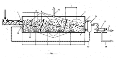
- the figure shows a fermentation device with a horizontal closed container 1, which has at the front end an entry opening 2 for substrate to be treated and at the opposite end discharge openings 3 and 4.
- the substrate which consists for example of biowaste or renewable raw materials, is introduced via a feed screw 5 into the entry opening 2 of the container 1.
- stirring devices 6 arranged transversely to the container axis, each of which has a stirrer shaft 11 which is oriented transversely to the container axis and which is driven individually.
- Stirrer bars 12 which are divided over the container width and mutually offset at angles of less than 120 degrees, are arranged on the stirrer shaft on the agitating blades of the agitators 6.
- the agitator shafts 11 are arranged with axial distances which are smaller than the stirrer diameter, so that there is a combing of the stirring bars 12.
- the overlapping region (combing zone) of adjacent agitators 6 is designated by the reference numeral 13.
- the maximum height of the sediment discharge 14 in the dead spaces between the rotating stirrer bars 12 can be predetermined technologically in the desired manner.
- sediment is piled on one side and removed from the staggered running, intermeshing stirring bar follower on the other side and transported across the ground to the next dune.
- the biogas produced in the container during the treatment is drawn off from the container 1 via an exhaust gas opening 15.
Description
Die Erfindung betrifft eine Fermentationseinrichtung zum biologischen Abbau von organisches Material enthaltendem Substrat und zur Gewinnung des beim Abbau entstehenden Biogases mit einem längserstreckten geschlossenen Behälter mit einer stirnseitigen Einbringöffnung für das Substrat und einer Austragsöffnung für behandeltes Substrat am gegenüberliegenden Ende des Behälters sowie mindestens einer Abzugsöffnung für Biogas, wobei der Behälter mehrere Reaktionsvolumenzellen aufweist, die jeweils mehrere individuell angetriebene Rühreinrichtungen mit kreisförmig bewegten Rührflügeln und quer zur Längserstreckung des Behälters liegenden Rührerwellen zum Durchmischen des Substrats enthalten, sowie ein Verfahren zum Betrieb der Fermentationseinrichtung.The invention relates to a fermentation device for the biodegradation of organic material containing substrate and recovery of biogas formed during degradation with an elongated closed container having a frontal introduction opening for the substrate and a discharge opening for treated substrate at the opposite end of the container and at least one vent for biogas wherein the container comprises a plurality of reaction volume cells, each containing a plurality of individually driven agitating means with circularly moving stirring blades and transverse to the longitudinal extent of the container lying agitator shafts for mixing the substrate, and a method for operating the fermentation device.
Bei der Fermentation von organisches Material enthaltendem Substrat, z.B. von Bioabfall, Rückständen aus der Nahrungsmittelproduktion oder nachwachsenden Rohstoffen, unterscheidet man zwischen der sogenannten Nassvergärung und der sogenannten Trockenvergärung. Während bei der Nassvergärung eine fließfähige Suspension aus dem Substrat hergestellt wird, die in einem Biogasreaktor, z.B. einem Schlaufenreaktor mit innenliegender Schlaufenströmung, behandelt wird, wird das Substrat bei der Trockenvergärung z.B. an einem Ende in einen geschlossenen liegenden Behälter eingebracht, mittels einer Rühreinrichtung unter Biogasbildung umgewälzt und das behandelte Substrat am anderen Ende aus dem Behälter abgezogen.In the fermentation of organic material-containing substrate, e.g. of biowaste, residues from food production or renewable raw materials, a distinction between the so-called wet fermentation and the so-called dry fermentation. While in wet fermentation, a flowable suspension is prepared from the substrate which is stored in a biogas reactor, e.g. a loop reactor with internal loop flow, the substrate is subjected to dry fermentation, e.g. introduced at one end in a closed-lying container, circulated by means of a stirring device with biogas formation and the treated substrate at the other end withdrawn from the container.
Die Verfahren der Trockenvergärung werden alternativ zu denen der Nassvergärung eingesetzt, wenn das anaerob zu behandelnde Substrat sehr-feststoffreich ist und deshalb die notwendige Verdünnung bis in den Betriebsbereich der Nassverfahren mit ihren Feststoffkonzentrationen von weniger als ca. 15% unwirtschaftlich ist, bzw. wenn die häufig notwendige, aber kostenaufwendige Störstoffentfrachtung bei Nassverfahren aus sonstigen prozesstechnischen Gründen nicht erforderlich ist. Trockenvergärungen werden bevorzugt bei Feststoffgehalten von gleich oder kleiner als 35% im Fermentereintritt gefahren und können als stehende oder liegende Reaktoren ausgeführt sein.The methods of dry fermentation are used as an alternative to those of wet fermentation, when the anaerobically treated substrate is very rich in solids and therefore the necessary dilution is uneconomical up to the operating range of the wet process with their solids concentrations of less than about 15%, or if the often necessary, but costly Störstoffentfrachtung wet process for other procedural reasons is not required. Dry fermentations are preferred at solids contents of equal to or less than 35% in water Run fermenter entry and can be designed as a standing or horizontal reactors.
Ein Vorteil der Trockenvergärung beim Einsatz in der Abfall- und Restmüllbehandlung ist der vergleichsweise geringe Aufbereitungs- und Konditionierungsaufwand für die angenommenen Eingangsstoffe vor der Vergärung. Nach einer Abreicherung grober Störstoffe und anschließender Zerkleinerung der Fraktion für die Vergärung auf 20 bis 60 mm ist in der Regel vor der Dosierung in den Gärreaktor keine weitere Störstoffentfrachtung für z.B. Holz, Plastik, Glas sowie Sand und Steine notwendig.An advantage of dry fermentation when used in waste and residual waste treatment is the comparatively low treatment and conditioning effort for the assumed input materials before fermentation. After a depletion of coarse impurities and subsequent comminution of the fraction for fermentation to 20 to 60 mm is usually before metering into the fermentation reactor no further Störententfrachtung for example. Wood, plastic, glass as well as sand and stones necessary.
Erkauft wird dieser geringe technologische Aufwand für die Einsatzvorbehandlung mit möglichen Problemen im Fermenter selbst. Durch den biochemischen Umsatz organischer Verbindungen im Gärmedium über die Fermenterlänge verringern sich zwischen Einbringöffnung und Austragsöffnung die Feststoffkonzentrationen von etwa 35% Trockensubstand auf kleiner als 20% Trockensubstanz und die Viskosität von 30.000 bis 60.000 mPas auf bis zu kleiner 5.000 mPas. Waren in dem feststoffreichen Einsatz die weiter oben genannten sedimentierfähigen und flotierfähigen Störstoffe weitgehend lagestabil verteilt, werden sie durch die sich verändernden Stoffeigenschaften des Gärmediums im Fermenter mobilisiert, was tendenziell zur Ausbildung von Sink- und Schwimmschichten führt. Die üblicherweise in Fermentern angeordneten Rührorgane zur Verbesserung von Stoffübergang und Medienentgasung unterstützen diese fraktionierte Entmischung noch.Due to the biochemical conversion of organic compounds in the fermentation medium over the fermenter length, the solids concentrations of about 35% dry substandard to less than 20% dry matter and the viscosity of. Are reduced between the feed opening and the discharge opening 30,000 to 60,000 mPas to less than 5,000 mPas. Goods in the high-solids use the above sedimentable and floatable impurities largely stable distributed, they are mobilized by the changing material properties of the fermentation medium in the fermenter, which tends to lead to the formation of sinking and floating layers. The usually arranged in fermenters stirrers to improve mass transfer and media degassing support this fractional segregation yet.
Deshalb finden sich insbesondere in liegenden Trockenfermentern neben Rührorganen noch besondere Vorrichtungen hauptsächlich zum Transport und zur Entnahme von Sedimenten.Therefore, especially in lying dry fermenters in addition to stirrers still special devices mainly for the transport and removal of sediments.
So sind in der
Bei dieser bekannten Konstruktion werden also für die Durchmischung und die Störstoffentnahme getrennte Ausrüstungen benötigt, was den technologischen und betriebstechnischen Aufwand erhöht. Insbesondere Wartung und Störungsbehebung bringen erhebliche Probleme, da sie mit einem Abfahren des Fermenters verbunden sein können.In this known construction separate equipment is therefore required for the mixing and the removal of foreign matter, which increases the technological and operational expenses. In particular maintenance and troubleshooting bring significant problems, since they can be associated with a shutdown of the fermenter.
In der
Der vorliegenden Erfindung liegt die Aufgabe zugrunde, eine Fermentationseinrichtung der eingangs genannten Art sowie ein Verfahren zum Betrieb der Fermentationseinrichtung so auszugestalten, dass neben der eigentlichen Homogenisier- und Entgasungsfunktion der Rührwerke ohne Beeinträchtigung der Pfropfenstromcharakteristik für den Feststoffstrom zwischen Fermenterein- und austritt gleichzeitig eine Sedimentbewegung zum Fermenterende induziert und die Ausbildung verfestigter Schwimmdecken unterdrückt wird.The present invention has for its object to provide a fermentation device of the type mentioned and a method for operating the fermentation device so that in addition to the actual homogenization and degassing of the agitators without affecting the Pfropfenstromcharakteristik for the flow of solids between fermenter inlet and outlet at the same time a sediment movement Fermenterende induced and the formation of solidified floating blankets is suppressed.
Diese Aufgabe wird erfindungsgemäß bei der Fermentationseinrichtung dadurch gelöst, dass die Rührerwellen mit Achsabständen angeordnet sind, die kleiner sind als der Rührdurchmesser, so dass die Rührflügel beim Drehen der Rührerwellen einen Überlappungsbereich überstreichen.This object is achieved according to the invention in the fermentation device in that the stirrer shafts are arranged with axial spacings which are smaller than the stirrer diameter, so that the stirring vanes cover an overlapping region when the stirrer shafts are rotated.
Die Erfindung geht dabei von dem Stand der Technik aus, wie er in der
Aus theoretischen Überlegungen, die experimentell bestätigt wurden, hat sich überraschend gezeigt, dass dieses Rührsystem auch für den gezielten Sedimenttransport längs des Fermenterbodens genutzt werden kann. Dazu wird der von Wanderdünen bekannte Effekt der horizontalen Verschiebung durch Materialtransport von der Luv- auf die Leeseite ausgenutzt. Transportvehikel sind dabei die Rührflügel, die bei entsprechend ausgelegtem Abstand zum Reaktorboden die Sedimente zu einer Düne quer zur Längsachse des Behälters zusammenschieben. Bei den derzeitig üblichen Rührergeometrien und Achsabständen verläuft dieser Transportvorgang jedoch ineffektiv und kann völlig zum Stillstand kommen bzw. sogar zum Festfahren der Rührwerke führen in Abhängigkeit von Trockensubstanzgehalt, Medienviskosität und Störstoffanteil.From theoretical considerations, which were confirmed experimentally, it has surprisingly been found that this stirring system can also be used for targeted sediment transport along the fermenter bottom. For this purpose, the well-known by moving dunes effect of horizontal displacement is utilized by material transport from the windward to the leeward. Transport vehicles are the stirring blades, which push the sediments to a dune transversely to the longitudinal axis of the container at a correspondingly designed distance from the bottom of the reactor. In the currently common Rührergeometrien and center distances, however, this transport process is ineffective and can come to a complete standstill or even lead to trapping of the agitators depending on dry matter content, viscosity and impurity content.
In einer besonders bevorzugten Ausführungsform der Erfindung weisen die Rührflügel an ihren äußeren Enden Rührbalken auf, die über die Breite des Behälters geteilt und wechselseitig versetzt angeordnet sind. Wie sich nämlich gezeigt hat, sollten die Sedimentdünen klein genug bleiben, um beweglich zu sein. Dazu werden die Rührbalken über die Reaktorbreite geteilt und wechselseitig bevorzugt in Winkeln unter 120 Grad oder 90 Grad versetzt auf der Rührerwelle angeordnet. In Kombination mit der speziellen Geometrie des Rührsystems, bei der die Rührerwellen mit Achsabständen angeordnet sind, die kleiner sind als der Rührerdurchmesser, lässt sich die maximale Höhe der Sedimentaufwerfung in den Toträumen zwischen den rotierenden Rührbalken geometrisch in der gewünschten Weise vorgeben. Bei gleichsinniger Drehrichtung der benachbarten Rührwerke wird Sediment auf der einen Seite angehäuft und von dem versetzt laufenden, kämmenden Rührbalken des Folgerührwerks auf der anderen Seite wieder abgetragen und über den Boden bis zur nächsten Düne transportiert. Durch die in Querrichtung geteilten und auf der Welle versetzt angeordneten Rührbalken wird vermieden, dass der Rührbalken über die ganze Breite gleichzeitig in das Sediment eintaucht und es dadurch zu Schäden infolge mechanischer Überlastung kommt. Außerdem können sich seitlich keine Grobstoffe zwischen Rührbalken und Behälterwand verklemmen.In a particularly preferred embodiment of the invention, the stirring blades at their outer ends on stirring bars, which are divided over the width of the container and arranged mutually offset. As it has been shown, the sediment dunes should remain small enough to be mobile. For this purpose, the stirring bars are divided over the reactor width and mutually preferably arranged at angles below 120 degrees or 90 degrees offset on the agitator shaft. In combination with the special geometry of the stirring system, in which the stirrer shafts are arranged with axial distances which are smaller than the stirrer diameter, the maximum height of the sediment impingement in the dead spaces between the rotating stirrer bars can be set geometrically in the desired manner. In the same direction of rotation of the adjacent agitators sediment is accumulated on one side and removed by the staggered running, intermeshing stirring bar of the follower on the other side and transported across the ground to the next dune. The stirrer bars, which are divided in the transverse direction and are offset on the shaft, prevent the stirring bar from simultaneously being immersed in the sediment over the entire width, which leads to damage as a result of mechanical overloading. In addition, no coarse material between the stirring bar and the container wall can jam on the side.
Zweckmäßigerweise ist im Austragsbereich der Fermentationseinrichtung ein bodennaher Saugstutzen zum Abzug der dorthin transportierten Sedimente angeordnet. Insbesondere für die Behandlung von Gärmedien mit speziellen Sedimenteigenschaften ist gemäß einer Weiterbildung des Erfindungsgedankens bauseitig im Austragsbereich der Fermentationseinrichtung eine Sammeltasche mit geneigten Wänden ausgebildet, an deren tiefsten Punkt der Saugstutzen endet.Conveniently, in the discharge region of the fermentation device, a suction connection near the bottom is arranged for the withdrawal of the sediments transported there. In particular, for the treatment of fermentation media with special sediment properties is according to a development of the inventive concept on site in the discharge of the fermentation device formed a collection bag with inclined walls, at the lowest point of the suction nozzle ends.
Die Erfindung betrifft ferner ein Verfahren zum biologischen Abbau von organisches Material enthaltendem Substrat und zur Gewinnung des beim Abbau entstehenden Biogases, wobei das Substrat in einen längserstreckten geschlossenen Behälter eingebracht wird, im Behälter mehrere Reaktionszonen durchströmt, in denen es mittels jeweils individuell angetriebener Rühreinrichtungen mit kreisförmig um quer zur Längserstreckung des Behälters liegende Achsen bewegte Rührflügeln umgewälzt wird und Abbauprodukte aus dem Behälter abgezogen werden.The invention further relates to a method for biodegradation of organic material-containing substrate and for recovering the degradation resulting biogas, wherein the substrate is placed in a longitudinally extended closed container, flows through several reaction zones in the container, in which it by means of individually driven agitators with circular moving agitator blades are circulated around axes transverse to the longitudinal extension of the container, and degradation products are withdrawn from the container.
Verfahrensseitig wird die gestellte Aufgabe dadurch gelöst, die Rührflügel benachbarter Rührwerke, die mit Achsabständen angeordnet sind, die kleiner sind als der Rührdurchmesser, so gesteuert werden, dass die Rührflügel auf Lücke arbeiten. Dadurch wird sichergestellt, dass sich die Rührflügel benachbarter Rührwerke nicht gegenseitig blockieren.In terms of the method, the stated object is achieved in that the stirring blades of adjacent agitators, which are arranged with axial distances which are smaller than the stirring diameter, are controlled so that the stirring blades operate on a gap. This ensures that the impellers of adjacent agitators do not block each other.
Die Rührflügel benachbarter Rührwerke werden gleichsinnig bewegt. Durch die gleichsinnige Drehrichtung wird Sediment auf der einen Seite angehäuft und von dem versetzt laufenden, kämmenden Rührbalken des benachbarten Rührwerks auf der anderen Seite wieder abgetragen und über den Boden bis zur nächsten Düne transportiert.The agitator blades of adjacent agitators are moved in the same direction. Due to the direction of rotation in the same direction, sediment is accumulated on one side and removed by the staggered, intermeshing stirring bar of the adjacent agitator on the other side and transported across the ground to the next dune.
Die Erfindung eignet sich für alle Fermentationseinrichtungen, die einen liegenden Behälter mit querliegenden Rühreinrichtungen aufweisen: Insbesondere bei der Behandlung von Substrat, das eine hohe Sedimentierneigung besitzt, kann die Erfindung mit großem Vorteil angewandt werden.The invention is suitable for all fermentation devices having a horizontal container with transverse agitators: in particular in the treatment of substrate having a high Sedimentierneigung, the invention can be applied with great advantage.
Insgesamt wird mit der Erfindung mit geringem Investitionsaufwand eine technisch elegante Lösung zur gleichzeitigen Durchmischung von Fermentationsgut und Austrag von abgelagerten Sedimenten im Fermenter zur Verfügung gestellt. Ein besonderer Vorteil besteht dabei darin, dass die Pfropfenstromcharakteristik bezüglich des zu behandelnden Substrats in der Fermentationseinrichtung durch den Sedimentaustrag nicht gestört wird.Overall, a technically elegant solution for simultaneous mixing of Fermentationsgut and discharge of sediment deposited in the fermenter is provided with the invention with little investment. A particular advantage consists in the fact that the plug flow characteristic with respect to the substrate to be treated in the fermentation device is not disturbed by the Sedimentaustrag.
Im Folgenden soll die Erfindung anhand eines in der Figur schematisch dargestellten Ausführungsbeispiels näher erläutert werden:.In the following, the invention will be explained in more detail with reference to an embodiment schematically shown in the figure.
Die Figur zeigt eine Fermentationseinrichtung mit einem liegenden geschlossenen Behälter 1, der am stirnseitigen Ende eine Eintragsöffnung 2 für zu behandelndes Substrat und am gegenüberliegenden Ende Austragsöffnungen 3 und 4 aufweist. Das Substrat, das beispielsweise aus Bioabfall oder nachwachsenden Rohstoffen besteht, wird über eine Zuführschnecke 5 in die Eintragsöffnung 2 des Behälters 1 eingebracht. Im Behälter 1 sind quer zur Behälterachse angeordnete Rühreinrichtungen 6 angeordnet, die jeweils eine quer zur Behälterachse ausgerichtete Rührerwelle 11 aufweisen, welche individuell angetrieben wird. An den Rührflügeln der Rührwerke 6 sind Rührbalken 12 angebracht, die über die Behälterbreite geteilt und wechselseitig in Winkeln unter 120 Grad versetzt auf der Rührerwelle angeordnet sind. Außerdem sind die Rührerwellen 11 mit Achsabständen angeordnet, die kleiner sind als der Rührerdurchmesser, so dass es zu einem Kämmen der Rührbalken 12 kommt. Der Überlappungsbereich (Kämmzone) benachbarter Rührwerke 6 ist mit der Bezugsziffer 13 bezeichnet. Durch geometrische Festlegung der Achsabstände 6 sowie der Rührerdurchmesser in der Konstruktionsphase lässt sich die maximale Höhe der Sedimentaufwerfung 14 in den Toträumen zwischen den rotierenden Rührbalken 12 technologisch in der gewünschten Weise vorgeben. Bei gleichsinniger Drehrichtung der benachbarten Rührwerke 6 wird Sediment auf der einen Seite angehäuft und von dem versetzt laufenden, kämmenden Rührbalken des Folgerührwerks auf der anderen Seite wieder abgetragen und über den Boden bis zur nächsten Düne transportiert. Das während der Behandlung im Behälter erzeugte Biogas wird über eine Abgasöffnung 15 aus dem Behälter 1 abgezogen. Die zum Fermenterende transportierten Sedimentdünen 14 gelangen in den Bereich der Austragsöffnung 4, wo Trockensubstanz und sedimentangereicherte Bodenfraktion aus dem Behälter 1 abgesaugt werden. Feststoffarme Flüssigkeit wird im oberen Bereich des Behälters über die Austragsöffnung 3 abgeführt. In einem nachgeschaltetem Behälter 16 wird Gärgut abgetrennt und einer Entwässerungspresse 18 zugeführt. Abgeschiedene Gärreststoffe werden schließlich über eine Ableitung 19 abgezogen, während Presswasser z.B. als Flüssigdünger über eine Leitung 20 abgeführt wird. Über eine Rücklaufleitung 17 wird Faulgut und Presswasser zum stirnseitigen Ende des Behälters 1 bedarfsweise zurückgeführt.The figure shows a fermentation device with a horizontal closed container 1, which has at the front end an entry opening 2 for substrate to be treated and at the opposite end discharge openings 3 and 4. The substrate, which consists for example of biowaste or renewable raw materials, is introduced via a
Claims (5)
- Dry fermentation device for the biodegradation of substrate containing organic material and for recovering the biogas produced during degradation, with an elongate, closed container (1) having an end-side introduction opening (2) for the substrate and a discharge opening (3, 4) for treated substrate at the opposite end of the container (1), and at least one take-off opening (15) for biogas, wherein the container (1) has a plurality of reaction volume cells which each contain a plurality of individually driven stirring devices (6) having stirring blades, which move in a circular manner in the same direction, and stirrer shafts (11), which lie transversely with respect to the longitudinal extent of the container (1), for thoroughly mixing the substrate, characterized in that the stirrer shafts (11) are arranged at axial distances (7) which are smaller than the stirrer diameter, and therefore the stirring blades move through an overlapping region (13) during the rotation of the stirrer shafts (11).
- Fermentation device according to Claim 1, characterized in that the outer ends of the stirring blades have stirring bars (12) which are divided over the width of the container (1) and are arranged offset in an alternating manner.
- Fermentation device according to Claim 1 or 2, characterized in that a suction connecting pipe (4) in the vicinity of the base is arranged in the discharge region of the fermentation device in order to take off sediment.
- Fermentation device according to Claim 3, characterized in that, in the discharge region of the fermentation device, the container (1) has a collecting pocket with inclined walls, with the suction connecting pipe (4) ending at the lowermost point of said collecting pocket.
- Dry fermentation method for the biodegradation of substrate containing organic material and for recovering the biogas produced during degradation, wherein the substrate is introduced into an elongate, closed container (1), flows through a plurality of reaction zones in the container (1), in which reaction zones said substrate is circulated by means of stirring devices (6) which are each driven individually and have stirring blades moving circularly in the same direction about axes (11) lying transversely with respect to the longitudinal extent of the container (1), and degradation products are taken off out of the container (1), characterized in that the stirring blades of adjacent stirring mechanisms (6), which are arranged at axial distances which are smaller than the stirrer diameter, are controlled in such a manner that the stirring blades operate in a staggered manner.
Priority Applications (1)
| Application Number | Priority Date | Filing Date | Title |
|---|---|---|---|
| PL06829215T PL1987129T3 (en) | 2005-12-05 | 2006-11-30 | Fermentation device comprising a coupled substrate and sediment transport mechanism and method for operating the fermentation device |
Applications Claiming Priority (2)
| Application Number | Priority Date | Filing Date | Title |
|---|---|---|---|
| DE200510057978 DE102005057978A1 (en) | 2005-12-05 | 2005-12-05 | Fermentation device with coupled substrate and sediment transport and method for operating the fermentation device |
| PCT/EP2006/011518 WO2007065597A1 (en) | 2005-12-05 | 2006-11-30 | Fermentation device comprising a coupled substrate and sediment transport mechanism and method for operating the fermentation device |
Publications (2)
| Publication Number | Publication Date |
|---|---|
| EP1987129A1 EP1987129A1 (en) | 2008-11-05 |
| EP1987129B1 true EP1987129B1 (en) | 2014-04-02 |
Family
ID=37845345
Family Applications (1)
| Application Number | Title | Priority Date | Filing Date |
|---|---|---|---|
| EP20060829215 Active EP1987129B1 (en) | 2005-12-05 | 2006-11-30 | Fermentation device comprising a coupled substrate and sediment transport mechanism and method for operating the fermentation device |
Country Status (10)
| Country | Link |
|---|---|
| US (1) | US8241869B2 (en) |
| EP (1) | EP1987129B1 (en) |
| JP (1) | JP4881956B2 (en) |
| CN (1) | CN101360816B (en) |
| AU (1) | AU2006322351B2 (en) |
| CA (1) | CA2635376C (en) |
| DE (1) | DE102005057978A1 (en) |
| ES (1) | ES2467767T3 (en) |
| PL (1) | PL1987129T3 (en) |
| WO (1) | WO2007065597A1 (en) |
Families Citing this family (16)
| Publication number | Priority date | Publication date | Assignee | Title |
|---|---|---|---|---|
| DE202007009095U1 (en) | 2007-06-26 | 2008-11-13 | Agratec Ag | fermentation plant |
| DE102010025636A1 (en) * | 2010-06-30 | 2012-01-05 | Beutler & Lang Schalungs- und Behälter-Bau GmbH | Vacuum tank, system and method for removing contaminants from a biogas plant |
| UA107669C2 (en) * | 2010-11-09 | 2015-02-10 | Kompoferm Gmbh | Method for treating waste |
| JP2014509252A (en) * | 2011-01-19 | 2014-04-17 | アルジー アクア−カルチャー テクノロジー, インコーポレイテッド | Biological purification system, its components, methods of use, and products derived therefrom |
| FI125284B (en) * | 2013-11-21 | 2015-08-14 | Biogts Oy | A process for the production of biogas from biomass by anaerobic digestion and a corresponding reactor |
| CN104399734B (en) * | 2014-10-30 | 2017-02-22 | 温玉友 | Household garbage disposal equipment |
| CN104928154A (en) * | 2015-06-14 | 2015-09-23 | 农业部沼气科学研究所 | High-concentration material biogas fermentation tank discharging device |
| CN105462821A (en) * | 2016-01-15 | 2016-04-06 | 河南省立丰实业有限公司 | Large horizontal tunnel kiln spiral continuous dry-type anaerobic fermentation equipment |
| DE102016009223A1 (en) | 2016-07-28 | 2018-02-01 | Christine Apelt | Method for methane fermentation in the plug flow and apparatus for carrying out the method |
| CA3040004C (en) | 2016-10-11 | 2021-10-26 | Thoni Industriebetriebe Gmbh | Stirring device with improved stirring element configuration |
| FI128217B (en) | 2018-03-01 | 2019-12-31 | Doranova Oy | Anaerobic digestion reactor and plant |
| DE102019109999A1 (en) * | 2019-04-16 | 2020-10-22 | Michael Niederbacher | Plug flow fermenter for a biogas plant |
| CN113510133B (en) * | 2021-01-21 | 2023-06-23 | 上海艾尔天合环境科技有限公司 | Quick degradation device for kitchen wet garbage |
| DE102022108306A1 (en) * | 2022-04-06 | 2023-10-12 | Thöni Industriebetriebe Gmbh | Multi-level discharge system for a plug flow fermenter |
| WO2024032885A1 (en) * | 2022-08-10 | 2024-02-15 | Strabag Umwelttechnik Gmbh | Method for operating a fermentation device, and fermentation device |
| WO2024032884A1 (en) * | 2022-08-10 | 2024-02-15 | Strabag Umwelttechnik Gmbh | Method of operating a fermentation device |
Family Cites Families (9)
| Publication number | Priority date | Publication date | Assignee | Title |
|---|---|---|---|---|
| DE3239304C2 (en) * | 1982-10-23 | 1985-10-10 | H.F. Maack Wagenfabrik GmbH & Co KG, 2722 Visselhövede | Reactor for the production of biogas from liquid manure |
| JPH0322599A (en) * | 1989-06-20 | 1991-01-30 | Mitsubishi Electric Corp | Electronic component mounting equipment |
| JPH0536559Y2 (en) * | 1989-07-13 | 1993-09-16 | ||
| CH687526A5 (en) | 1993-02-25 | 1996-12-31 | Rindelaub Frank | Fermentation device. |
| JP3102631B2 (en) * | 1997-01-08 | 2000-10-23 | 鹿島道路株式会社 | Conveyor mixer |
| JP4397517B2 (en) | 2000-11-07 | 2010-01-13 | 椿本メイフラン株式会社 | Coolant liquid purification device |
| JP2002143812A (en) * | 2000-11-10 | 2002-05-21 | Shibuya Machinery Co Ltd | Device for treating organic waste |
| JP2004315259A (en) * | 2003-04-14 | 2004-11-11 | Atex Co Ltd | Stirring device for compost or the like |
| US7186335B2 (en) * | 2003-12-11 | 2007-03-06 | Linde-Kca-Dresden Gmbh | Process and device for biological treatment of a suspension in a bioreactor with integrated hydraulic top scum treatment |
-
2005
- 2005-12-05 DE DE200510057978 patent/DE102005057978A1/en not_active Withdrawn
-
2006
- 2006-11-30 EP EP20060829215 patent/EP1987129B1/en active Active
- 2006-11-30 ES ES06829215T patent/ES2467767T3/en active Active
- 2006-11-30 PL PL06829215T patent/PL1987129T3/en unknown
- 2006-11-30 CN CN200680051325.6A patent/CN101360816B/en active Active
- 2006-11-30 WO PCT/EP2006/011518 patent/WO2007065597A1/en active Application Filing
- 2006-11-30 US US12/096,083 patent/US8241869B2/en active Active
- 2006-11-30 JP JP2008543703A patent/JP4881956B2/en active Active
- 2006-11-30 CA CA 2635376 patent/CA2635376C/en active Active
- 2006-11-30 AU AU2006322351A patent/AU2006322351B2/en active Active
Also Published As
| Publication number | Publication date |
|---|---|
| CN101360816A (en) | 2009-02-04 |
| ES2467767T3 (en) | 2014-06-13 |
| CN101360816B (en) | 2015-06-03 |
| AU2006322351A1 (en) | 2007-06-14 |
| DE102005057978A1 (en) | 2007-06-06 |
| AU2006322351B2 (en) | 2010-07-01 |
| US20100062482A1 (en) | 2010-03-11 |
| EP1987129A1 (en) | 2008-11-05 |
| JP2009518170A (en) | 2009-05-07 |
| US8241869B2 (en) | 2012-08-14 |
| PL1987129T3 (en) | 2014-09-30 |
| JP4881956B2 (en) | 2012-02-22 |
| CA2635376A1 (en) | 2007-06-14 |
| CA2635376C (en) | 2011-07-05 |
| WO2007065597A1 (en) | 2007-06-14 |
Similar Documents
| Publication | Publication Date | Title |
|---|---|---|
| EP1987129B1 (en) | Fermentation device comprising a coupled substrate and sediment transport mechanism and method for operating the fermentation device | |
| EP0876311B1 (en) | Process for biologically treating organic materials and device for carrying out this process | |
| EP1841853B1 (en) | Method and device for operating a horizontal plug-flow fermenter | |
| EP1756021A1 (en) | Method and fermenter for the anaerobic fermentation of biological waste | |
| DE19624268C2 (en) | Process and device for recycling organic waste | |
| EP1987130B1 (en) | Fermentation device and method for recovering biogas | |
| DE2356697A1 (en) | METHOD AND EQUIPMENT FOR THE SOLIDIFICATION OF LIQUID Sludge | |
| CH687526A5 (en) | Fermentation device. | |
| DE202006013772U1 (en) | Biogas production plant comprises housing, fermentation tank to receive fermentation material, biogas storage connected with the fermentation tank, and feeding device to supply solid fermentation material into the fermentation | |
| AT11640U1 (en) | DEVICE FOR THE GASTRONOMIC SUBMISSION OF A FURNACE | |
| EP2371525B2 (en) | Twin screw extruder and method for the thermo-mechanical pulping of organic raw and residual materials | |
| DE202008010638U1 (en) | Agitator with injection system for solids | |
| EP1541239A1 (en) | Device for shredding of solids, adding of liquid and transporting of made suspension into converting plant | |
| WO2004074181A2 (en) | Catalytic reactor | |
| WO2009000900A2 (en) | Fermentation plant | |
| DE102007025903A1 (en) | Device for producing biogas by continuous dry fermentation of stackable biomass, has fermentation chamber, inserting unit for inserting biomass in fermentation chamber, and movement device for moving biomass in stacked form | |
| DE3605258A1 (en) | METHOD AND DEVICE FOR COMPOSTING SOLID AND LIQUID ORGANIC WASTE | |
| DE19846336A1 (en) | Treating refuse containing both inert and organic materials | |
| DE102006032734A1 (en) | Device for removing sediments from fermentation device for biological degradation of organic material and for extracting biogas, comprises a closed container, discharge opening, a suction pipe socket near the base, and departure opening | |
| EP2465918B1 (en) | Biomass dry fermenter with continuous loading and emptying | |
| WO2024032885A1 (en) | Method for operating a fermentation device, and fermentation device | |
| WO2005121052A1 (en) | Method and device for dewatering fermentation residues | |
| DE3149344A1 (en) | Circulating device for blending and homogenising layers of deposited and suspended matter in digestion chambers in order to produce biogas, without mechanical frictional or pneumatic drive | |
| DE7716758U1 (en) | DEVICE FOR COMPOSTING ORGANIC WASTE | |
| WO1999047473A1 (en) | Method and device for treating waste |
Legal Events
| Date | Code | Title | Description |
|---|---|---|---|
| PUAI | Public reference made under article 153(3) epc to a published international application that has entered the european phase |
Free format text: ORIGINAL CODE: 0009012 |
|
| 17P | Request for examination filed |
Effective date: 20080909 |
|
| AK | Designated contracting states |
Kind code of ref document: A1 Designated state(s): AT BE BG CH CY CZ DE DK EE ES FI FR GB GR HU IE IS IT LI LT LU LV MC NL PL PT RO SE SI SK TR |
|
| 17Q | First examination report despatched |
Effective date: 20081230 |
|
| RAP1 | Party data changed (applicant data changed or rights of an application transferred) |
Owner name: STRABAG UMWELTANLAGEN GMBH |
|
| DAX | Request for extension of the european patent (deleted) | ||
| GRAP | Despatch of communication of intention to grant a patent |
Free format text: ORIGINAL CODE: EPIDOSNIGR1 |
|
| INTG | Intention to grant announced |
Effective date: 20131219 |
|
| GRAS | Grant fee paid |
Free format text: ORIGINAL CODE: EPIDOSNIGR3 |
|
| GRAA | (expected) grant |
Free format text: ORIGINAL CODE: 0009210 |
|
| AK | Designated contracting states |
Kind code of ref document: B1 Designated state(s): AT BE BG CH CY CZ DE DK EE ES FI FR GB GR HU IE IS IT LI LT LU LV MC NL PL PT RO SE SI SK TR |
|
| REG | Reference to a national code |
Ref country code: GB Ref legal event code: FG4D Free format text: NOT ENGLISH |
|
| REG | Reference to a national code |
Ref country code: AT Ref legal event code: REF Ref document number: 660151 Country of ref document: AT Kind code of ref document: T Effective date: 20140415 Ref country code: CH Ref legal event code: EP |
|
| REG | Reference to a national code |
Ref country code: IE Ref legal event code: FG4D Free format text: LANGUAGE OF EP DOCUMENT: GERMAN |
|
| REG | Reference to a national code |
Ref country code: DE Ref legal event code: R096 Ref document number: 502006013650 Country of ref document: DE Effective date: 20140508 |
|
| REG | Reference to a national code |
Ref country code: RO Ref legal event code: EPE |
|
| REG | Reference to a national code |
Ref country code: ES Ref legal event code: FG2A Ref document number: 2467767 Country of ref document: ES Kind code of ref document: T3 Effective date: 20140613 |
|
| REG | Reference to a national code |
Ref country code: NL Ref legal event code: T3 |
|
| REG | Reference to a national code |
Ref country code: SE Ref legal event code: TRGR |
|
| REG | Reference to a national code |
Ref country code: LT Ref legal event code: MG4D |
|
| REG | Reference to a national code |
Ref country code: PL Ref legal event code: T3 |
|
| REG | Reference to a national code |
Ref country code: GR Ref legal event code: EP Ref document number: 20140401288 Country of ref document: GR Effective date: 20140901 |
|
| PG25 | Lapsed in a contracting state [announced via postgrant information from national office to epo] |
Ref country code: CY Free format text: LAPSE BECAUSE OF FAILURE TO SUBMIT A TRANSLATION OF THE DESCRIPTION OR TO PAY THE FEE WITHIN THE PRESCRIBED TIME-LIMIT Effective date: 20140402 Ref country code: LT Free format text: LAPSE BECAUSE OF FAILURE TO SUBMIT A TRANSLATION OF THE DESCRIPTION OR TO PAY THE FEE WITHIN THE PRESCRIBED TIME-LIMIT Effective date: 20140402 Ref country code: IS Free format text: LAPSE BECAUSE OF FAILURE TO SUBMIT A TRANSLATION OF THE DESCRIPTION OR TO PAY THE FEE WITHIN THE PRESCRIBED TIME-LIMIT Effective date: 20140802 |
|
| PG25 | Lapsed in a contracting state [announced via postgrant information from national office to epo] |
Ref country code: LV Free format text: LAPSE BECAUSE OF FAILURE TO SUBMIT A TRANSLATION OF THE DESCRIPTION OR TO PAY THE FEE WITHIN THE PRESCRIBED TIME-LIMIT Effective date: 20140402 |
|
| PG25 | Lapsed in a contracting state [announced via postgrant information from national office to epo] |
Ref country code: PT Free format text: LAPSE BECAUSE OF FAILURE TO SUBMIT A TRANSLATION OF THE DESCRIPTION OR TO PAY THE FEE WITHIN THE PRESCRIBED TIME-LIMIT Effective date: 20140804 |
|
| REG | Reference to a national code |
Ref country code: DE Ref legal event code: R097 Ref document number: 502006013650 Country of ref document: DE |
|
| PG25 | Lapsed in a contracting state [announced via postgrant information from national office to epo] |
Ref country code: EE Free format text: LAPSE BECAUSE OF FAILURE TO SUBMIT A TRANSLATION OF THE DESCRIPTION OR TO PAY THE FEE WITHIN THE PRESCRIBED TIME-LIMIT Effective date: 20140402 Ref country code: DK Free format text: LAPSE BECAUSE OF FAILURE TO SUBMIT A TRANSLATION OF THE DESCRIPTION OR TO PAY THE FEE WITHIN THE PRESCRIBED TIME-LIMIT Effective date: 20140402 Ref country code: SK Free format text: LAPSE BECAUSE OF FAILURE TO SUBMIT A TRANSLATION OF THE DESCRIPTION OR TO PAY THE FEE WITHIN THE PRESCRIBED TIME-LIMIT Effective date: 20140402 |
|
| PLBE | No opposition filed within time limit |
Free format text: ORIGINAL CODE: 0009261 |
|
| STAA | Information on the status of an ep patent application or granted ep patent |
Free format text: STATUS: NO OPPOSITION FILED WITHIN TIME LIMIT |
|
| 26N | No opposition filed |
Effective date: 20150106 |
|
| REG | Reference to a national code |
Ref country code: DE Ref legal event code: R097 Ref document number: 502006013650 Country of ref document: DE Effective date: 20150106 |
|
| REG | Reference to a national code |
Ref country code: HU Ref legal event code: AG4A Ref document number: E022449 Country of ref document: HU |
|
| PG25 | Lapsed in a contracting state [announced via postgrant information from national office to epo] |
Ref country code: LU Free format text: LAPSE BECAUSE OF FAILURE TO SUBMIT A TRANSLATION OF THE DESCRIPTION OR TO PAY THE FEE WITHIN THE PRESCRIBED TIME-LIMIT Effective date: 20141130 Ref country code: MC Free format text: LAPSE BECAUSE OF FAILURE TO SUBMIT A TRANSLATION OF THE DESCRIPTION OR TO PAY THE FEE WITHIN THE PRESCRIBED TIME-LIMIT Effective date: 20140402 |
|
| PG25 | Lapsed in a contracting state [announced via postgrant information from national office to epo] |
Ref country code: SI Free format text: LAPSE BECAUSE OF FAILURE TO SUBMIT A TRANSLATION OF THE DESCRIPTION OR TO PAY THE FEE WITHIN THE PRESCRIBED TIME-LIMIT Effective date: 20140402 |
|
| REG | Reference to a national code |
Ref country code: IE Ref legal event code: MM4A |
|
| PG25 | Lapsed in a contracting state [announced via postgrant information from national office to epo] |
Ref country code: IE Free format text: LAPSE BECAUSE OF NON-PAYMENT OF DUE FEES Effective date: 20141130 |
|
| REG | Reference to a national code |
Ref country code: FR Ref legal event code: PLFP Year of fee payment: 10 |
|
| PG25 | Lapsed in a contracting state [announced via postgrant information from national office to epo] |
Ref country code: TR Free format text: LAPSE BECAUSE OF FAILURE TO SUBMIT A TRANSLATION OF THE DESCRIPTION OR TO PAY THE FEE WITHIN THE PRESCRIBED TIME-LIMIT Effective date: 20140402 |
|
| REG | Reference to a national code |
Ref country code: FR Ref legal event code: PLFP Year of fee payment: 11 |
|
| REG | Reference to a national code |
Ref country code: FR Ref legal event code: PLFP Year of fee payment: 12 |
|
| PGFP | Annual fee paid to national office [announced via postgrant information from national office to epo] |
Ref country code: PL Payment date: 20221118 Year of fee payment: 17 Ref country code: BE Payment date: 20221118 Year of fee payment: 17 |
|
| PGFP | Annual fee paid to national office [announced via postgrant information from national office to epo] |
Ref country code: NL Payment date: 20231122 Year of fee payment: 18 |
|
| PGFP | Annual fee paid to national office [announced via postgrant information from national office to epo] |
Ref country code: GB Payment date: 20231123 Year of fee payment: 18 Ref country code: GR Payment date: 20231120 Year of fee payment: 18 |
|
| PGFP | Annual fee paid to national office [announced via postgrant information from national office to epo] |
Ref country code: ES Payment date: 20231215 Year of fee payment: 18 |
|
| PGFP | Annual fee paid to national office [announced via postgrant information from national office to epo] |
Ref country code: SE Payment date: 20231123 Year of fee payment: 18 Ref country code: RO Payment date: 20231122 Year of fee payment: 18 Ref country code: IT Payment date: 20231130 Year of fee payment: 18 Ref country code: HU Payment date: 20231129 Year of fee payment: 18 Ref country code: FR Payment date: 20231124 Year of fee payment: 18 Ref country code: FI Payment date: 20231120 Year of fee payment: 18 Ref country code: DE Payment date: 20231120 Year of fee payment: 18 Ref country code: CZ Payment date: 20231120 Year of fee payment: 18 Ref country code: CH Payment date: 20231201 Year of fee payment: 18 Ref country code: BG Payment date: 20231117 Year of fee payment: 18 Ref country code: AT Payment date: 20231117 Year of fee payment: 18 |
|
| PGFP | Annual fee paid to national office [announced via postgrant information from national office to epo] |
Ref country code: PL Payment date: 20231120 Year of fee payment: 18 Ref country code: BE Payment date: 20231121 Year of fee payment: 18 |