EP1986286A2 - Connector - Google Patents
Connector Download PDFInfo
- Publication number
- EP1986286A2 EP1986286A2 EP08007634A EP08007634A EP1986286A2 EP 1986286 A2 EP1986286 A2 EP 1986286A2 EP 08007634 A EP08007634 A EP 08007634A EP 08007634 A EP08007634 A EP 08007634A EP 1986286 A2 EP1986286 A2 EP 1986286A2
- Authority
- EP
- European Patent Office
- Prior art keywords
- housing
- connector according
- tube portion
- rear end
- portions
- Prior art date
- Legal status (The legal status is an assumption and is not a legal conclusion. Google has not performed a legal analysis and makes no representation as to the accuracy of the status listed.)
- Withdrawn
Links
- XLYOFNOQVPJJNP-UHFFFAOYSA-N water Substances O XLYOFNOQVPJJNP-UHFFFAOYSA-N 0.000 claims description 13
- 230000013011 mating Effects 0.000 claims description 6
- 230000004308 accommodation Effects 0.000 claims description 3
- 230000002093 peripheral effect Effects 0.000 claims description 3
- 210000000078 claw Anatomy 0.000 description 18
- 238000007789 sealing Methods 0.000 description 7
- 238000005192 partition Methods 0.000 description 3
- 230000000694 effects Effects 0.000 description 2
- 238000009434 installation Methods 0.000 description 2
- 238000009413 insulation Methods 0.000 description 2
- 229920003002 synthetic resin Polymers 0.000 description 2
- 239000000057 synthetic resin Substances 0.000 description 2
- 239000011248 coating agent Substances 0.000 description 1
- 238000000576 coating method Methods 0.000 description 1
- 230000001419 dependent effect Effects 0.000 description 1
- 239000000463 material Substances 0.000 description 1
- 238000009751 slip forming Methods 0.000 description 1
Images


Classifications
-
- H—ELECTRICITY
- H01—ELECTRIC ELEMENTS
- H01R—ELECTRICALLY-CONDUCTIVE CONNECTIONS; STRUCTURAL ASSOCIATIONS OF A PLURALITY OF MUTUALLY-INSULATED ELECTRICAL CONNECTING ELEMENTS; COUPLING DEVICES; CURRENT COLLECTORS
- H01R13/00—Details of coupling devices of the kinds covered by groups H01R12/70 or H01R24/00 - H01R33/00
- H01R13/62—Means for facilitating engagement or disengagement of coupling parts or for holding them in engagement
- H01R13/629—Additional means for facilitating engagement or disengagement of coupling parts, e.g. aligning or guiding means, levers, gas pressure electrical locking indicators, manufacturing tolerances
- H01R13/631—Additional means for facilitating engagement or disengagement of coupling parts, e.g. aligning or guiding means, levers, gas pressure electrical locking indicators, manufacturing tolerances for engagement only
-
- H—ELECTRICITY
- H01—ELECTRIC ELEMENTS
- H01R—ELECTRICALLY-CONDUCTIVE CONNECTIONS; STRUCTURAL ASSOCIATIONS OF A PLURALITY OF MUTUALLY-INSULATED ELECTRICAL CONNECTING ELEMENTS; COUPLING DEVICES; CURRENT COLLECTORS
- H01R13/00—Details of coupling devices of the kinds covered by groups H01R12/70 or H01R24/00 - H01R33/00
- H01R13/62—Means for facilitating engagement or disengagement of coupling parts or for holding them in engagement
- H01R13/629—Additional means for facilitating engagement or disengagement of coupling parts, e.g. aligning or guiding means, levers, gas pressure electrical locking indicators, manufacturing tolerances
- H01R13/633—Additional means for facilitating engagement or disengagement of coupling parts, e.g. aligning or guiding means, levers, gas pressure electrical locking indicators, manufacturing tolerances for disengagement only
-
- H—ELECTRICITY
- H01—ELECTRIC ELEMENTS
- H01R—ELECTRICALLY-CONDUCTIVE CONNECTIONS; STRUCTURAL ASSOCIATIONS OF A PLURALITY OF MUTUALLY-INSULATED ELECTRICAL CONNECTING ELEMENTS; COUPLING DEVICES; CURRENT COLLECTORS
- H01R13/00—Details of coupling devices of the kinds covered by groups H01R12/70 or H01R24/00 - H01R33/00
- H01R13/46—Bases; Cases
- H01R13/52—Dustproof, splashproof, drip-proof, waterproof, or flameproof cases
- H01R13/5219—Sealing means between coupling parts, e.g. interfacial seal
- H01R13/5221—Sealing means between coupling parts, e.g. interfacial seal having cable sealing means
-
- H—ELECTRICITY
- H01—ELECTRIC ELEMENTS
- H01R—ELECTRICALLY-CONDUCTIVE CONNECTIONS; STRUCTURAL ASSOCIATIONS OF A PLURALITY OF MUTUALLY-INSULATED ELECTRICAL CONNECTING ELEMENTS; COUPLING DEVICES; CURRENT COLLECTORS
- H01R13/00—Details of coupling devices of the kinds covered by groups H01R12/70 or H01R24/00 - H01R33/00
- H01R13/46—Bases; Cases
- H01R13/52—Dustproof, splashproof, drip-proof, waterproof, or flameproof cases
- H01R13/5227—Dustproof, splashproof, drip-proof, waterproof, or flameproof cases with evacuation of penetrating liquids
-
- H—ELECTRICITY
- H01—ELECTRIC ELEMENTS
- H01R—ELECTRICALLY-CONDUCTIVE CONNECTIONS; STRUCTURAL ASSOCIATIONS OF A PLURALITY OF MUTUALLY-INSULATED ELECTRICAL CONNECTING ELEMENTS; COUPLING DEVICES; CURRENT COLLECTORS
- H01R13/00—Details of coupling devices of the kinds covered by groups H01R12/70 or H01R24/00 - H01R33/00
- H01R13/62—Means for facilitating engagement or disengagement of coupling parts or for holding them in engagement
- H01R13/627—Snap or like fastening
- H01R13/6271—Latching means integral with the housing
- H01R13/6272—Latching means integral with the housing comprising a single latching arm
-
- H—ELECTRICITY
- H01—ELECTRIC ELEMENTS
- H01R—ELECTRICALLY-CONDUCTIVE CONNECTIONS; STRUCTURAL ASSOCIATIONS OF A PLURALITY OF MUTUALLY-INSULATED ELECTRICAL CONNECTING ELEMENTS; COUPLING DEVICES; CURRENT COLLECTORS
- H01R13/00—Details of coupling devices of the kinds covered by groups H01R12/70 or H01R24/00 - H01R33/00
- H01R13/62—Means for facilitating engagement or disengagement of coupling parts or for holding them in engagement
- H01R13/629—Additional means for facilitating engagement or disengagement of coupling parts, e.g. aligning or guiding means, levers, gas pressure electrical locking indicators, manufacturing tolerances
- H01R13/633—Additional means for facilitating engagement or disengagement of coupling parts, e.g. aligning or guiding means, levers, gas pressure electrical locking indicators, manufacturing tolerances for disengagement only
- H01R13/6335—Additional means for facilitating engagement or disengagement of coupling parts, e.g. aligning or guiding means, levers, gas pressure electrical locking indicators, manufacturing tolerances for disengagement only comprising a handle
Definitions
- the present invention relates to a connector.
- a front part of a housing of a watertight connector is formed to have a double tube structure comprised of an inner tube portion and an outer tube portion. If a mating housing is fitted between the inner and outer tube portions with a sealing rubber ring mounted on the outer circumferential surface of the inner tube portion accommodating terminal fittings, sealing is provided between male and female housings by this rubber ring. Accordingly, a rear part of a housing is smaller than a front part and the wall thereof is thinned to such an extent as to maximally eliminate an unnecessary wall material in a general watertight connector, wherefore the frame structure of cavities are exposed in many cases.
- An example of such a connector is disclosed in Japanese Unexamined Patent Publication No. 2005-216614 .
- the rear part of the housing is mainly the frame structure of the cavities and there is no space for providing a suitable pushable surface used upon connecting the housings.
- the housings have been conventionally connected and separated while holding the outer circumferential surface of the outer tube portion of the front part of the housing.
- the present invention was developed in view of the above situation and an object thereof is to provide a connector enabling a smooth housing connecting operation.
- a connector comprising:
- the extended portion projects more outward than the wall portion forming the cavity located at the end, the rear surface of the extended portion can be provided as a pushable or operable surface usable upon connecting the housings. Since the operation recess is so formed before the extended portion as to be retracted inwardly as compared to the extended portion, the housings can be connected by gripping this operation recess. Since the extended portion also functions as a part to be gripped also upon separating the housings, a separating operation can be easily performed.
- a plurality of cavities for at least partly accommodating one or more terminal fittings are formed substantially side by side and the at least one extended portion projecting laterally outward from the rear end of a wall portion forming the cavity located at an end in the arranging direction.
- the outer side surface of the extended portion in a projecting direction is set to be substantially flush with or slightly retracted inwardly of the outer side surface of the outer tube portion with respect to the projecting direction.
- the entire connector is not enlarged.
- the housing can be gripped from the outer tube portion to the extended portion, wherefore the miniaturization of the housing can be dealt with.
- unevenness as at least one slip stopper is formed on the outer surface of the operation recess.
- slip can be stopped upon connecting and separating the housings by gripping the operation recess.
- one or more relatively recessed regions are formed in the rear end surface of the housing preferably in correspondence with an at least partial accommodation of the terminal fittings having different sizes, wherein water entering in the relatively recessed regions is drained by way of one or more drainage paths.
- a peripheral edge of the rear end surface of the housing projects from the rear end surface of the female housing over at least part of, preferably over the substantially entire width range, where the resilient plug accommodating portions for at least partly accommodating resilient plugs are provided, thereby forming at least one surrounding wall.
- the surrounding wall is not preset in the width range corresponding to part of the resilient plug accommodating portions by forming at least one cutout portion.
- the connector further comprises a lock arm engageable with an interlocking portion of the mating connector housing so as to lock the connector housings properly connected with each other.
- the lock arm comprises a pair of arm pieces such that there are two disengagement modes from the interlocking portion acting in two different directions being arranged at an angle different from 0° or 180°, preferably substantially normal to each other, one disengagement mode being preferably such as to widen the spacing between two lock pieces.
- one or more restricting protuberances are provided for selectively restricting resilient deformations of the arm piece(s).
- front end surfaces of the restricting protuberances are inclined surfaces and/or side surfaces of the restricting protuberances in longitudinal intermediate parts are substantially flat surfaces, which serve as restricting surfaces substantially in parallel with the outer side surfaces of the lock arm.
- an engagement margin of the lock arm and the interlocking portions is set larger than the spacing between the Icok arm and the restricting surfaces.
- one or more drain openings are located at the positions lateral to the lock arm.
- FIG. 1 shows an intermediate male connector
- a housing 1 made e.g. of synthetic resin is preferably at least partly divided into front and rear parts by at least one partition wall 2 in an intermediate part (preferably substantially in a middle part) in forward and backward directions FBD, and the front and rear parts preferably substantially are in the form of rectangular tubes open forward and backward.
- male terminal fittings 3A, 3B are arranged substantially side by side in width direction WD (at one or more stages) with the respective heights thereof substantially aligned.
- a pair of large-size male terminal fittings 3A having a larger width are arranged at the opposite widthwise ends, and four small-size male terminal fittings 3B are arranged between the male terminal fittings 3A.
- the front end positions of the male terminal fittings 3A, 3B are substantially aligned in forward and backward directions FBD regardless of the sizes thereof, but the rear end positions of the large-size male terminal fittings 3A are located more backward.
- At least one standing wall 4 (rib) (preferably substantially in the form of a flat plate) is provided in a widthwise intermediate position (preferably substantially in the widthwise center) of the lateral (upper) surface of the male housing 1.
- This standing wall 4 is formed substantially along the connecting direction CD of the male and female housings 1, 5, and the front end thereof preferably is set at a position slightly retracted backward from the opening edge of the male housing 1.
- one or more, preferably a pair of interlocking portions 6 project toward the opposite widthwise side(s) from the front upper end of the standing wall 4.
- the front end surface(s) of the (preferably both) interlocking portion(s) 6 is/are formed into guiding surface(s) 6A sloped downward or inward toward the back in the connecting direction CD, and the rear end surfaces thereof are formed into reverse-taper receiving surfaces 6B sloped upward or outward toward the front in the connecting direction CD.
- One or more projecting edges 7 used to place fingers upon connecting and separating the male and female housings 1, 5 are formed to project from the lateral (upper) side toward or to the opposite lateral (bottom) side of the outer circumferential surface near the rear end of the male housing 1.
- FIGS. 4 to 8 show the housing 5 of a female connector, wherein the female housing 5 is made e.g. of synthetic resin and includes an inner tube portion 8 and an outer tube portion 9 at least partly surrounding the inner tube portion 8 from the outer side, and the both tube portions 8, 9 preferably are connected at (preferably the rear end surface of) the female housing 5.
- a connection space 10 open forward is defined between the both tube portions 8, 9, and the front part of the male housing 1 is at least partly fittable or insertable thereinto.
- a front end part of the male housing 1 is held in close contact with the outer circumferential surface of a sealing resilient (preferably rubber) ring 11 mounted on (preferably a back end portion of) the inner tube portion 8, whereby sealing is provided between the male and female housings 1, 5.
- a sealing resilient (preferably rubber) ring 11 mounted on (preferably a back end portion of) the inner tube portion 8, whereby sealing is provided between the male and female housings 1, 5.
- the outer tube portion 9 preferably includes a bottom wall 9A, a pair of side walls 9B standing at an angle different from 0° or 180°, preferably substantially substantially vertically from or near the opposite widthwise ends of the bottom wall 9A, a pair of inclined or bent walls 9C extending substantially obliquely toward each other from the opposite side walls 9B and a horizontal upper wall 9D connecting the opposite inclined walls 9C.
- a step 12 is formed between the upper wall 9D and the rear part of the housing 5. Further, a window hole 13 is formed in the widthwise middle part of a rear upper wall 9D1 near a front upper wall 9D2.
- the inner tube portion 8 is formed with one or more, preferably a plurality of cavities 15A, 15B for at least partly accommodating one or more female terminal fittings 14, and the respective cavities 15A, 15B penetrate the inner tube portion 8 substantially in the connecting direction CD, i.e. in forward and backward directions FBD.
- those arranged at the opposite widthwise ends preferably are larger cavities 15A (as preferred cavities of a first kind) for at least partly accommodating large-size female terminal fittings (not shown, as preferred female terminal fittings of a first kind), and one or more (e.g.
- the female terminal fittings 14 are or may be similar in shape regardless of whether they are large size or small-size and/or the sizes thereof may differ depending on allowable currents.
- the female terminal fittings 14 are connected with wire cores by wire connecting portions (preferably comprising one or more barrel portions or wire barrels) formed continuously with main portions 16 (preferably substantially in the form of rectangular tubes).
- wire connecting portions preferably comprising one or more barrel portions or wire barrels
- main portions 16 preferably substantially in the form of rectangular tubes.
- a watertight resilient (preferably rubber) plug 19 is mounted on or to an end of the insulation coating of each wire 18 and the wire connection portion (preferably the barrel portion or insulation barrel) of the female terminal fitting 14 is connected (preferably crimped or bent or folded into connection) with this resilient/rubber plug 19.
- each of the cavities 15A, 15B in the connecting direction CD preferably is formed to have a substantially rectangular or polygonal cross section and at least partly accommodates the main portion 16 of the corresponding female terminal fitting 14, whereas the rear portion (preferably substantially the rear half) thereof in the connecting direction CD serves as a substantially cylindrical resilient plug accommodating portion 20A, 20B slightly larger than the front portion (preferably the front half).
- These resilient plug accommodating portions 20A, 20B preferably are horizontally arranged substantially side by side in at least one row in width direction WD in the rear end surface of the female housing 5. Intervals between the respective resilient plug accommodating portions 20A, 20B are narrowed by connecting the adjacent ones.
- Those of the resilient plug accommodating portions 20A, 20B corresponding to the larger cavities 15A are formed to have a larger diameter, and a pair of resilient plug accommodating portions with the larger diameter (hereinafter, these resilient plug accommodating portions are referred to as “large-diameter accommodating portions 20A") are arranged at the opposite lateral (left and right) ends in FIG. 6 .
- the resilient plug accommodating portions corresponding to the smaller cavities 15B are formed to have a smaller diameter, and four resilient plug accommodating portions with the smaller diameter (hereinafter, these rubber plug accommodating portions are referred to as "small-diameter accommodating portions 20B") are arranged between the large-diameter accommodating portions 20A in width direction WD.
- the corresponding resilient (preferably rubber) plugs 19 are or can be at least partly accommodated into the large-diameter and small-diameter accommodating portions 20A, 20B, one or more sealing lips of the rubber plugs 19 come into close contact with the inner circumferential surface(s) of the resilient plug accommodating portions 20A, 20B to provide sealing.
- the rear end surfaces of the resilient (rubber) plugs 19 preferably substantially are flush with the rear end surfaces of the resilient (rubber) plug accommodating portions 20A, 20B or project slightly backward therefrom, so that water does not stay inside the respective resilient plug accommodating portions 20A, 20B.
- the large-diameter accommodating portions 20A are formed to have such a length that the rear end positions thereof are located more backward than the rear end surface of the female housing 5. Accordingly, a width range where the respective small-diameter accommodating portions 20B are provided forms a recessed region 21 relatively recessed as compared to the both large-diameter accommodating portions 20A.
- the outer surfaces of the opposite side walls 9B of the outer tube portion 9 preferably are continuously formed up to the rear end of the large-diameter accommodating portions 20A, whereby extended portions E for extending the width of the rear surface of the female housing 5 are formed at the outer sides of the both large-diameter accommodating portions 20A in width direction WD as shown in FIG. 7 .
- the rear surfaces of the both extended portions E particularly serve as pushable surfaces 22, which preferably are substantially flat surfaces in flush with the rear ends of the both large-diameter accommodating portions 20A and are each thinned at one or more positions, particularly four positions in the shown example.
- the outer surfaces of the side walls 9B of the outer tube portion 9 and the outer surfaces of the both extended portions E preferably are substantially flush with each other in width direction WD (the extended portions E may be slightly retracted inwardly in width direction WD).
- the side walls 9B in length ranges from an intermediate part (preferably substantially middle parts) of the side walls 9B in forward and backward directions FBD to the extended portions E, the side walls 9B preferably are gradually narrowed toward the extended portions E in the plan view.
- operation recesses 44 are formed in the side walls 9B to be retracted slightly inwardly as compared to the front parts of the side walls 9B in the connecting direction CD and the extended portions E.
- one or more, preferably a plurality of slip stoppers 45 in the form of substantially vertical strips or other types of unevenesses are formed substantially side by side in each operation recess 44, and preferably the lengths thereof gradually increase toward the back in the connecting direction CD.
- the rear end edges of the (preferably both) inclined walls 9C and that of the rear upper wall 9D2 preferably are formed to project backward from the rear end surface of the female housing 5 so as to be substantially aligned with the rear end positions of the large-diameter accommodating portions 20A.
- the peripheral edge of the rear end surface of the female housing 5 projects from the rear end surface of the female housing 5 over at least part of, preferably over the substantially entire width range where the resilient plug accommodating portions 20A, 20B are provided, thereby forming a surrounding wall 23.
- One or more connecting ribs 24 are so formed on the outer surface of each large-diameter accommodating portion 20A to extend substantially toward the opposite side(s) in height direction, wherein one connecting rib 24 is connected with the surrounding wall 23 and the other is bent at its extending end to be connected with an end wall surface and the connecting ribs 24 preferably are flush with the surrounding wall 23 and the pushable surface 22.
- at least one projecting rear wall 25 is formed in a widthwise intermediate part (preferably substantially in a widthwise middle part) of one side (upper side in FIG. 7 ) of the recessed area 21 in height direction in the rear end surface of the female housing 5, and preferably substantially is flush with the rear ends of the surrounding wall 23 and the large-diameter accommodating portions 20A.
- This projecting rear wall 25 is connected with the large-diameter accommodating portions 20A and the respective small-diameter accommodating portions 20B via one or more connecting leg portions.
- the surrounding wall 23 preferably is not provided at one side e.g. the lower side of FIG. 6 (side opposite to the side where a lock arm 27 to be described later is provided) and a cutout portion 28 is formed over such a length range preferably including the substantially entire width range of the recessed region 21 and/or substantially inner portions (preferably inner halves) of the opposite large-diameter accommodating portions 20A.
- This cutout portion 28 mainly functions to avoid interference with fingers upon inserting the female terminal fittings 14 into the respective small-diameter accommodating portions 20B and/or to drain water.
- beveling 29 preferably is made on the bottom edge of the cutout portion 28 over the entire width.
- Areas at the opposite widthwise sides of the projecting rear wall 25 are formed to communicate with the recessed region 21 and/or to be substantially flush with the recessed region 21 with respect to the connecting direction CD.
- One or more drain openings 31 are formed in the (preferably both) water drainage regions 31.
- one or more, preferably a pair of drainage paths 32 extending substantially in forward and backward directions FBD while preferably being spaced part in width direction WD are formed to penetrate the female housing 5 lateral (below or lower parts) of the opposite inclined walls 9C of the female housing 5 near the upper wall 9D, wherein the rear ends thereof preferably serve as the drain openings 31 in or near the rear end surface of the female housing 5 and/or the front ends thereof preferably serve as drain holes 33 in or near the front surface of the female housing 5.
- at least one vertical partition wall 34 preferably is provided in each the drain opening 31 to divide the drain opening 31 into a plurality of parts, preferably into left and right sides.
- a hollow chamber 35 preferably is formed substantially over at least part of, preferably over the substantially entire width range of the upper wall 9D below the upper wall 9D in the female housing 5, wherein the bottom side thereof communicates with the connection space 10 and the front side thereof makes a (preferably substantially rectangular) opening in or near the front surface of the female housing 5.
- the lock arm 27 is arranged in a widthwise intermediate position (preferably substantially in the widthwise center) of the interior of the hollow chamber 35. As shown in FIG. 9 , the lock arm 27 preferably includes a pair of arm pieces 36 facing each other while being spaced apart in width direction WD.
- the both arm pieces 36 are both cantilevers extending substantially forward from the projecting rear wall 25 and resiliently deformable in height direction (or a direction at an angle different from 0° or 180°, preferably substantially normal to the connecting direction CD).
- a claw portion 37 preferably is formed to project outward at the front end of each arm piece 36 and engageable with the corresponding interlocking portion 6 of the male housing 1.
- a connecting surface 38 connecting the both arm pieces 36 is provided at the inner surfaces of the both arm pieces 36 and behind the claw portions 37, and at least partly located in the window hole 13 to be pressable through the window hole 13.
- At least one slit 39 for receiving the standing wall 4 of the male housing 1 is formed at or near the front end edge of the connecting surface 38 to extend inwardly, and the connecting surface 38 is engageable with the both interlocking portions 6 while supporting them from below.
- the front surfaces of the claw portions 37 preferably are formed into deformation guiding surfaces 40 sloped downward or inwardly toward the back preferably over the substantially entire width ranges, and can guide slipping movements of the both arm pieces 36 by coming substantially into sliding contact with the interlocking portions 6 upon connecting the male and female housings 1, 5.
- the spacing between the two claw portions 37 is sufficiently narrower than the spacing between the outer side surfaces of the two interlocking portions 6 and slightly wider than the width of the standing wall 4.
- vertical walls 41 substantially face each other at the substantially opposite widthwise sides of the two arm pieces 36 in the hollow chamber 35.
- One or more, preferably a pair of restricting protuberances 42 project at one or more positions of the (preferably both) vertical walls 41 substantially facing the outer side(s) of the claw portion(s) 37 of the arm piece(s) 36 in width direction WD.
- the (preferably both) restricting protuberance(s) 42 preferably is/are for restricting outward resiliently deformations of the both arm pieces 36 and arranged substantially at the same height as the claw portions 37.
- the front end surfaces of the restricting protuberances 42 preferably are inclined surfaces, and the side surfaces thereof in longitudinal intermediate or middle parts are flat surfaces, which serve as restricting surfaces 43 substantially in parallel with the outer side surfaces of the claw portions 37.
- an engagement margin of the claw portions 37 and the interlocking portions 6 (dimension A in FIG. 13 ) preferably is set larger than the spacing between the claw portions 37 and the restricting surfaces 43 (dimension B in FIG. 13 ).
- the front end surface of the male housing 1 is substantially aligned with the front side of the connection space 10 of the female housing 5.
- the female housing 5 is, for example, pushed in this state preferably by gripping or operating the slip stoppers 45 of the opposite operation recesses 44.
- the operation recesses 44 preferably are gradually widened toward the front in the connecting direction CD, they can be easily gripped or manipulated upon performing the pushing operation and an operation force can be more easily transmitted to the female housing 5.
- no spaces, into which an operator can insert his fingers are provided at the lateral sides of the connector in some cases.
- the pushing or manipulation operation preferably can be applied to the pushable or manipulation surfaces 22 (as a preferred operable surface) instead of to the operation recesses 44 in this embodiment.
- fingers are placed against the both pushable surfaces 22 preferably while bundling the wires 18 drawn out from the respective resilient plug accommodating portions 20A, 20B, and the female housing 5 is pushed or operated or manipulated in this state.
- the standing wall 4 and the interlocking portions 6 of the male housing 1 preferably are at least partly inserted into the hollow chamber 35 of the female housing 5.
- the guiding surfaces 6A of the interlocking portions 6 come substantially into sliding contact with the (preferably both) disengagement guiding surface(s) 40 of the lock arm 27 to guide downward or inward resilient deformations of the arm pieces 36.
- the both arm pieces 36 are at least partly restored and the rear surfaces of the claw portions 37 are engaged with the receiving surfaces 6B of the interlocking portions 6.
- the male and female terminal fittings are substantially properly connected and the inner circumferential surface of the front end portion of the male housing 1 preferably is held in close contact with the outer circumferential surface of the resilient (preferably rubber) ring 11 over at least part, preferably over the substantially entire circumference, whereby sealing is provided between the male and female housings 1, 5.
- the lock arm 27 is obliged to have such a structure comprised of one or more, preferably a pair of arm pieces 36 preferably having separated front ends as in this embodiment, there can be two disengagement modes from the interlocking portion 6, i.e. downward or inward resilient deformations and resilient deformations in directions at an angle different from 0° or 180°, preferably substantially normal to the above downward or inward resilient deformations preferably to widen the spacing between the lock pieces 36.
- both arm pieces 36 try to be resiliently deformed in the directions at an angle different from 0° or 180°, preferably substantially normal to the above downward or inward resilient deformations preferably to widen the spacing therebetween, such deformations are restricted by the contact of the (preferably both) claw portion(s) 37 and the restricting protuberance(s) 42.
- the deformation(s) of the (preferably both) arm piece(s) 36 is/are restricted to downward or inward resilient deformations even if unlocking should be effected. Therefore, a stable locking force can be obtained.
- the connecting surface 38 is or can be pressed or operated through the window hole 13, whereupon the entire lock arm 27 is resiliently deformed downward or inward to disengage the claw portions 37 from the interlocking portions 6. If the female housing 5 is pulled in this state preferably by gripping the one or more operation recesses 44, the two housings 1, 5 can be separated. In this case, since the extended portions E can be gripped, a pulling force can be effectively exerted to the female housing 5.
- the rear end positions of the resilient plug accommodating portions 20A, 20B preferably are displaced in forward and backward directions FBD in this embodiment, there are the regions 21, 30 retracted backward with respect to the surrounding wall 23 and the like.
- the male and female housing 1, 5 are so held that the rear end surfaces thereof face substantially upward in the properly connected state, there is a likelihood that water is collected in the recessed regions 21, 30.
- water is or may be drained through the cutout portion(s) 28 at the lower end side of the recessed region 21 in FIG. 6 .
- drain opening(s) 31 is/are formed in the water drainage region(s) proximate to the small-diameter accommodating portions 20B, water having entered the water drainage regions passes or may pass from the drain openings 31 to the drainage paths 32 and is drained to the outside of the female housing 5 via the drain holes 33.
- a connector as particularly shown in FIGS. 14(A) and 14(B) , comprising:
- the extended portion projects more outward than the wall portion forming the cavity located at the end, the rear surface of the extended portion can be provided as a pushable surface usable upon connecting the housings. Since the operation recess is so formed before the extended portion as to be retracted inwardly as compared to the extended portion, the housings can be connected by gripping this operation recess. Since the extended portion also functions as a part to be gripped also upon separating the housings, a separating operation can be easily performed.
- a female housing 5 includes an inner tube portion 8 for at least partly accommodating one or more female terminal fittings 14 and an outer tube portion 9 at least partly surrounding the outer circumferential surface of the inner tube portion 8.
- One or more, preferably a plurality of cavities 15A, 15B are arranged (preferably substantially side by side) in the rear end surface of the female housing 5, one or more extended portions E project outward laterally, particularly in an arranging direction of the cavities from the cavities 15A located at ends in the arranging direction (widthwise direction WD), and the one or more rear end surfaces of the one or more extended portions E serve as pushable or operable surfaces 22 upon a connecting operation.
- One or more side walls 9B of the outer tube portion 9 preferably are continuous with the extended portions E, and one or more operation recesses 44 are formed in the respective side walls 9B before the extended portions E in a connecting direction CD.
Abstract
Description
- The present invention relates to a connector.
- Generally, a front part of a housing of a watertight connector is formed to have a double tube structure comprised of an inner tube portion and an outer tube portion. If a mating housing is fitted between the inner and outer tube portions with a sealing rubber ring mounted on the outer circumferential surface of the inner tube portion accommodating terminal fittings, sealing is provided between male and female housings by this rubber ring. Accordingly, a rear part of a housing is smaller than a front part and the wall thereof is thinned to such an extent as to maximally eliminate an unnecessary wall material in a general watertight connector, wherefore the frame structure of cavities are exposed in many cases. An example of such a connector is disclosed in Japanese Unexamined Patent Publication No.
2005-216614 - As described above, the rear part of the housing is mainly the frame structure of the cavities and there is no space for providing a suitable pushable surface used upon connecting the housings. Thus, the housings have been conventionally connected and separated while holding the outer circumferential surface of the outer tube portion of the front part of the housing.
- However, as the connector becomes more multipolar, the spacing between the opposite sides of the outer circumferential surface of outer tube portions widens. Thus, it becomes difficult to hold the connector. In addition, even if a slip stopper is provided on the outer circumferential surface, there is no sufficient gripping structure, wherefore it has been difficult to effectively exert a pushing force.
- The present invention was developed in view of the above situation and an object thereof is to provide a connector enabling a smooth housing connecting operation.
- This object is solved according to the invention by the features of the independent claims. Preferred embodiments of the invention are subject of the dependent claims.
- According to the invention, there is provided a connector, comprising:
- a housing including an inner tube portion, in which one or more cavities for at least partly accommodating one or more terminal fittings are formed, and an outer tube portion arranged to at least partly surround at least a front side of the inner tube portion in a connecting direction, a connection space, into which a mating housing is at least partly fittable, being defined between the inner tube portion and the outer tube portion,
- at least one extended portion projecting laterally outward from the rear end of a wall portion forming the most lateral cavity, and
- at least one operation recess arranged before the extended portion in a connecting direction and having a projecting distance smaller than that of the extended portion.
- Accordingly, since the extended portion projects more outward than the wall portion forming the cavity located at the end, the rear surface of the extended portion can be provided as a pushable or operable surface usable upon connecting the housings. Since the operation recess is so formed before the extended portion as to be retracted inwardly as compared to the extended portion, the housings can be connected by gripping this operation recess. Since the extended portion also functions as a part to be gripped also upon separating the housings, a separating operation can be easily performed.
- According to a preferred embodiment of the invention, a plurality of cavities for at least partly accommodating one or more terminal fittings are formed substantially side by side and the at least one extended portion projecting laterally outward from the rear end of a wall portion forming the cavity located at an end in the arranging direction.
- Preferably, the outer side surface of the extended portion in a projecting direction is set to be substantially flush with or slightly retracted inwardly of the outer side surface of the outer tube portion with respect to the projecting direction.
- Accordingly, since the projecting distance of the extended portion is equal to or smaller than that of the outer tube portion, the entire connector is not enlarged. In the case of connecting the housing using an automatic machine, the housing can be gripped from the outer tube portion to the extended portion, wherefore the miniaturization of the housing can be dealt with.
- Further preferably, unevenness as at least one slip stopper is formed on the outer surface of the operation recess.
- Accordingly, slip can be stopped upon connecting and separating the housings by gripping the operation recess.
- Still further preferably, one or more relatively recessed regions are formed in the rear end surface of the housing preferably in correspondence with an at least partial accommodation of the terminal fittings having different sizes, wherein water entering in the relatively recessed regions is drained by way of one or more drainage paths.
- Further preferably, a peripheral edge of the rear end surface of the housing projects from the rear end surface of the female housing over at least part of, preferably over the substantially entire width range, where the resilient plug accommodating portions for at least partly accommodating resilient plugs are provided, thereby forming at least one surrounding wall.
- Most preferably, the surrounding wall is not preset in the width range corresponding to part of the resilient plug accommodating portions by forming at least one cutout portion.
- According to a further preferred embodiment, the connector further comprises a lock arm engageable with an interlocking portion of the mating connector housing so as to lock the connector housings properly connected with each other.
- Preferably, the lock arm comprises a pair of arm pieces such that there are two disengagement modes from the interlocking portion acting in two different directions being arranged at an angle different from 0° or 180°, preferably substantially normal to each other, one disengagement mode being preferably such as to widen the spacing between two lock pieces.
- Further preferably, one or more restricting protuberances are provided for selectively restricting resilient deformations of the arm piece(s).
- Still further preferably, front end surfaces of the restricting protuberances are inclined surfaces and/or side surfaces of the restricting protuberances in longitudinal intermediate parts are substantially flat surfaces, which serve as restricting surfaces substantially in parallel with the outer side surfaces of the lock arm.
- Further preferably, an engagement margin of the lock arm and the interlocking portions is set larger than the spacing between the Icok arm and the restricting surfaces.
- Most preferably, one or more drain openings are located at the positions lateral to the lock arm.
- These and other objects, features and advantages of the present invention will become more apparent upon reading of the following detailed description of preferred embodiments and accompanying drawings. It should be understood that even though embodiments are separately described, single features thereof may be combined to additional embodiments.
-
FIG. 1 is a plan view of a male connector, -
FIG. 2 is a front view of the male connector, -
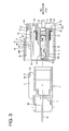
FIG. 3 is a side view in section of male and female connectors, -
FIG. 4 is a front view of a housing of the female connector, -
FIG. 5 is a plan view of the housing of the female connector, -
FIG. 6 is a side view of the housing of the female connector, -
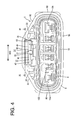
FIG. 7 is a rear view of the housing of the female connector, -
FIG. 8 is a section along VIII-VIII ofFIG. 7 , -
FIG. 9 is a section along IX-IX ofFIG. 4 , -
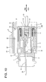
FIG. 10 is a section cut at a position shown inFIG. 8 showing a connected state of the male and female connectors, -
FIG. 11 is a section cut in the widthwise center showing the connected state of the male and female connectors, -
FIG. 12 is a section corresponding toFIG. 9 showing the connected state of the male and female connectors, -
FIG. 13 is an enlarged view showing a locked part by a lock arm, and -
FIGS. 14(A) and 14(B) are a plan view in section and a rear view showing the present invention. - One preferred embodiment of the present invention is described with reference to
FIGS. 1 to 13 .FIG. 1 shows an intermediate male connector, ahousing 1 made e.g. of synthetic resin is preferably at least partly divided into front and rear parts by at least onepartition wall 2 in an intermediate part (preferably substantially in a middle part) in forward and backward directions FBD, and the front and rear parts preferably substantially are in the form of rectangular tubes open forward and backward. One or more, preferably a plurality of maleterminal fittings 3A (preferably of one first kind) and/or one or more, preferably a plurality of maleterminal fittings 3B (preferably of a sekond kind different of the first kind), both tab-shaped, preferably are pressed or inserted through thispartition wall 2 in forward and backward directions FBD. These maleterminal fittings male terminal fittings 3A having a larger width are arranged at the opposite widthwise ends, and four small-sizemale terminal fittings 3B are arranged between themale terminal fittings 3A. The front end positions of themale terminal fittings male terminal fittings 3A are located more backward. - At least one standing wall 4 (rib) (preferably substantially in the form of a flat plate) is provided in a widthwise intermediate position (preferably substantially in the widthwise center) of the lateral (upper) surface of the
male housing 1. This standingwall 4 is formed substantially along the connecting direction CD of the male andfemale housings male housing 1. Further, one or more, preferably a pair of interlockingportions 6 project toward the opposite widthwise side(s) from the front upper end of the standingwall 4. The front end surface(s) of the (preferably both) interlocking portion(s) 6 is/are formed into guiding surface(s) 6A sloped downward or inward toward the back in the connecting direction CD, and the rear end surfaces thereof are formed into reverse-taperreceiving surfaces 6B sloped upward or outward toward the front in the connecting direction CD. - One or more projecting
edges 7 used to place fingers upon connecting and separating the male andfemale housings male housing 1. -
FIGS. 4 to 8 show thehousing 5 of a female connector, wherein thefemale housing 5 is made e.g. of synthetic resin and includes aninner tube portion 8 and anouter tube portion 9 at least partly surrounding theinner tube portion 8 from the outer side, and the bothtube portions female housing 5. Aconnection space 10 open forward is defined between the bothtube portions male housing 1 is at least partly fittable or insertable thereinto. At the time of connection, a front end part of themale housing 1 is held in close contact with the outer circumferential surface of a sealing resilient (preferably rubber)ring 11 mounted on (preferably a back end portion of) theinner tube portion 8, whereby sealing is provided between the male andfemale housings - The
outer tube portion 9 preferably includes abottom wall 9A, a pair ofside walls 9B standing at an angle different from 0° or 180°, preferably substantially substantially vertically from or near the opposite widthwise ends of thebottom wall 9A, a pair of inclined orbent walls 9C extending substantially obliquely toward each other from theopposite side walls 9B and a horizontalupper wall 9D connecting the oppositeinclined walls 9C. Astep 12 is formed between theupper wall 9D and the rear part of thehousing 5. Further, awindow hole 13 is formed in the widthwise middle part of a rear upper wall 9D1 near a front upper wall 9D2. - The
inner tube portion 8 is formed with one or more, preferably a plurality ofcavities terminal fittings 14, and therespective cavities inner tube portion 8 substantially in the connecting direction CD, i.e. in forward and backward directions FBD. Out of thecavities larger cavities 15A (as preferred cavities of a first kind) for at least partly accommodating large-size female terminal fittings (not shown, as preferred female terminal fittings of a first kind), and one or more (e.g. four)smaller cavities 15B (as preferred cavities of a second kind) for at least partly accommodating small-size female terminal fittings 14 (as preferred female terminal fittings of a second kind different from the first kind) are arranged substantially side by side adjacent to or between thelarger cavities 15A in the shown example. When the male andfemale housings terminal fittings 14 and the small-size femaleterminal fittings 14 are or can be properly electrically connected with the large-sizemale terminal fittings 3A and the small-sizemale terminal fittings 3B, respectively. - The female
terminal fittings 14 are or may be similar in shape regardless of whether they are large size or small-size and/or the sizes thereof may differ depending on allowable currents. The femaleterminal fittings 14 are connected with wire cores by wire connecting portions (preferably comprising one or more barrel portions or wire barrels) formed continuously with main portions 16 (preferably substantially in the form of rectangular tubes). A watertight resilient (preferably rubber) plug 19 is mounted on or to an end of the insulation coating of eachwire 18 and the wire connection portion (preferably the barrel portion or insulation barrel) of the female terminal fitting 14 is connected (preferably crimped or bent or folded into connection) with this resilient/rubber plug 19. - The front portion (preferably substantially the front half) of each of the
cavities main portion 16 of the corresponding female terminal fitting 14, whereas the rear portion (preferably substantially the rear half) thereof in the connecting direction CD serves as a substantially cylindrical resilient plugaccommodating portion accommodating portions female housing 5. Intervals between the respective resilient plugaccommodating portions accommodating portions larger cavities 15A are formed to have a larger diameter, and a pair of resilient plug accommodating portions with the larger diameter (hereinafter, these resilient plug accommodating portions are referred to as "large-diameteraccommodating portions 20A") are arranged at the opposite lateral (left and right) ends inFIG. 6 . The resilient plug accommodating portions corresponding to thesmaller cavities 15B are formed to have a smaller diameter, and four resilient plug accommodating portions with the smaller diameter (hereinafter, these rubber plug accommodating portions are referred to as "small-diameteraccommodating portions 20B") are arranged between the large-diameteraccommodating portions 20A in width direction WD. When the corresponding resilient (preferably rubber) plugs 19 are or can be at least partly accommodated into the large-diameter and small-diameteraccommodating portions accommodating portions accommodating portions accommodating portions accommodating portions - Although the rear ends of the respective small-diameter
accommodating portions 20B preferably are substantially flush with the rear end surface of thefemale housing 5, the large-diameteraccommodating portions 20A are formed to have such a length that the rear end positions thereof are located more backward than the rear end surface of thefemale housing 5. Accordingly, a width range where the respective small-diameteraccommodating portions 20B are provided forms a recessedregion 21 relatively recessed as compared to the both large-diameteraccommodating portions 20A. - The outer surfaces of the
opposite side walls 9B of theouter tube portion 9 preferably are continuously formed up to the rear end of the large-diameteraccommodating portions 20A, whereby extended portions E for extending the width of the rear surface of thefemale housing 5 are formed at the outer sides of the both large-diameteraccommodating portions 20A in width direction WD as shown inFIG. 7 . The rear surfaces of the both extended portions E particularly serve aspushable surfaces 22, which preferably are substantially flat surfaces in flush with the rear ends of the both large-diameteraccommodating portions 20A and are each thinned at one or more positions, particularly four positions in the shown example. - As shown in
FIG. 5 , in the plan view of thefemale housing 5, the outer surfaces of theside walls 9B of theouter tube portion 9 and the outer surfaces of the both extended portions E preferably are substantially flush with each other in width direction WD (the extended portions E may be slightly retracted inwardly in width direction WD). However, in length ranges from an intermediate part (preferably substantially middle parts) of theside walls 9B in forward and backward directions FBD to the extended portions E, theside walls 9B preferably are gradually narrowed toward the extended portions E in the plan view. In other words, operation recesses 44 are formed in theside walls 9B to be retracted slightly inwardly as compared to the front parts of theside walls 9B in the connecting direction CD and the extended portions E. As shown inFIG. 6 , one or more, preferably a plurality ofslip stoppers 45 in the form of substantially vertical strips or other types of unevenesses are formed substantially side by side in eachoperation recess 44, and preferably the lengths thereof gradually increase toward the back in the connecting direction CD. - On the other hand, the rear end edges of the (preferably both) inclined
walls 9C and that of the rear upper wall 9D2 preferably are formed to project backward from the rear end surface of thefemale housing 5 so as to be substantially aligned with the rear end positions of the large-diameteraccommodating portions 20A. Thus, the peripheral edge of the rear end surface of thefemale housing 5 projects from the rear end surface of thefemale housing 5 over at least part of, preferably over the substantially entire width range where the resilient plugaccommodating portions wall 23. One or moreconnecting ribs 24 are so formed on the outer surface of each large-diameteraccommodating portion 20A to extend substantially toward the opposite side(s) in height direction, wherein one connectingrib 24 is connected with the surroundingwall 23 and the other is bent at its extending end to be connected with an end wall surface and the connectingribs 24 preferably are flush with the surroundingwall 23 and thepushable surface 22. Further, at least one projectingrear wall 25 is formed in a widthwise intermediate part (preferably substantially in a widthwise middle part) of one side (upper side inFIG. 7 ) of the recessedarea 21 in height direction in the rear end surface of thefemale housing 5, and preferably substantially is flush with the rear ends of the surroundingwall 23 and the large-diameteraccommodating portions 20A. This projectingrear wall 25 is connected with the large-diameteraccommodating portions 20A and the respective small-diameteraccommodating portions 20B via one or more connecting leg portions. - On the other hand, the surrounding
wall 23 preferably is not provided at one side e.g. the lower side ofFIG. 6 (side opposite to the side where alock arm 27 to be described later is provided) and acutout portion 28 is formed over such a length range preferably including the substantially entire width range of the recessedregion 21 and/or substantially inner portions (preferably inner halves) of the opposite large-diameteraccommodating portions 20A. Thiscutout portion 28 mainly functions to avoid interference with fingers upon inserting the femaleterminal fittings 14 into the respective small-diameteraccommodating portions 20B and/or to drain water. In this embodiment, beveling 29 preferably is made on the bottom edge of thecutout portion 28 over the entire width. - Areas at the opposite widthwise sides of the projecting rear wall 25 (areas at least partly surrounded (preferably at three sides) by the connecting
ribs 24, the surroundingwall 23 and/or the projecting rear wall 25: water drainage regions 30) are formed to communicate with the recessedregion 21 and/or to be substantially flush with the recessedregion 21 with respect to the connecting direction CD. One ormore drain openings 31 are formed in the (preferably both)water drainage regions 31. Specifically, one or more, preferably a pair ofdrainage paths 32 extending substantially in forward and backward directions FBD while preferably being spaced part in width direction WD are formed to penetrate thefemale housing 5 lateral (below or lower parts) of the oppositeinclined walls 9C of thefemale housing 5 near theupper wall 9D, wherein the rear ends thereof preferably serve as thedrain openings 31 in or near the rear end surface of thefemale housing 5 and/or the front ends thereof preferably serve as drain holes 33 in or near the front surface of thefemale housing 5. In the shown example, at least onevertical partition wall 34 preferably is provided in each thedrain opening 31 to divide thedrain opening 31 into a plurality of parts, preferably into left and right sides. - A
hollow chamber 35 preferably is formed substantially over at least part of, preferably over the substantially entire width range of theupper wall 9D below theupper wall 9D in thefemale housing 5, wherein the bottom side thereof communicates with theconnection space 10 and the front side thereof makes a (preferably substantially rectangular) opening in or near the front surface of thefemale housing 5. Thelock arm 27 is arranged in a widthwise intermediate position (preferably substantially in the widthwise center) of the interior of thehollow chamber 35. As shown inFIG. 9 , thelock arm 27 preferably includes a pair ofarm pieces 36 facing each other while being spaced apart in width direction WD. The botharm pieces 36 are both cantilevers extending substantially forward from the projectingrear wall 25 and resiliently deformable in height direction (or a direction at an angle different from 0° or 180°, preferably substantially normal to the connecting direction CD). Aclaw portion 37 preferably is formed to project outward at the front end of eacharm piece 36 and engageable with the corresponding interlockingportion 6 of themale housing 1. A connectingsurface 38 connecting the botharm pieces 36 is provided at the inner surfaces of the botharm pieces 36 and behind theclaw portions 37, and at least partly located in thewindow hole 13 to be pressable through thewindow hole 13. At least one slit 39 for receiving the standingwall 4 of themale housing 1 is formed at or near the front end edge of the connectingsurface 38 to extend inwardly, and the connectingsurface 38 is engageable with the both interlockingportions 6 while supporting them from below. The front surfaces of theclaw portions 37 preferably are formed into deformation guiding surfaces 40 sloped downward or inwardly toward the back preferably over the substantially entire width ranges, and can guide slipping movements of the botharm pieces 36 by coming substantially into sliding contact with the interlockingportions 6 upon connecting the male andfemale housings claw portions 37 is sufficiently narrower than the spacing between the outer side surfaces of the two interlockingportions 6 and slightly wider than the width of the standingwall 4. - On the other hand,
vertical walls 41 substantially face each other at the substantially opposite widthwise sides of the twoarm pieces 36 in thehollow chamber 35. One or more, preferably a pair of restrictingprotuberances 42 project at one or more positions of the (preferably both)vertical walls 41 substantially facing the outer side(s) of the claw portion(s) 37 of the arm piece(s) 36 in width direction WD. The (preferably both) restricting protuberance(s) 42 preferably is/are for restricting outward resiliently deformations of the botharm pieces 36 and arranged substantially at the same height as theclaw portions 37. The front end surfaces of the restrictingprotuberances 42 preferably are inclined surfaces, and the side surfaces thereof in longitudinal intermediate or middle parts are flat surfaces, which serve as restrictingsurfaces 43 substantially in parallel with the outer side surfaces of theclaw portions 37. As shown inFIG. 12 , with the bothclaw portions 37 of thelock arm 27 engaged with the interlockingportions 6 of themale housing 1, an engagement margin of theclaw portions 37 and the interlocking portions 6 (dimension A inFIG. 13 ) preferably is set larger than the spacing between theclaw portions 37 and the restricting surfaces 43 (dimension B inFIG. 13 ). Thus, as the botharm pieces 36 are resiliently deformed outward in width direction WD, theclaw portions 37 come into contact with the restrictingsurfaces 43 before theclaw portions 37 are disengaged from the interlockingportions 6, thereby avoiding a situation where thearm pieces 36 are further resiliently deformed to widen the spacing therebetween. - Next, functions and effects of this embodiment constructed as above are specifically described. In the case of connecting the male and
female housings male housing 1 is substantially aligned with the front side of theconnection space 10 of thefemale housing 5. Then, thefemale housing 5 is, for example, pushed in this state preferably by gripping or operating theslip stoppers 45 of the opposite operation recesses 44. At this time, since the operation recesses 44 preferably are gradually widened toward the front in the connecting direction CD, they can be easily gripped or manipulated upon performing the pushing operation and an operation force can be more easily transmitted to thefemale housing 5. Depending on an installation condition of the connector, no spaces, into which an operator can insert his fingers, are provided at the lateral sides of the connector in some cases. In such cases, the pushing or manipulation operation preferably can be applied to the pushable or manipulation surfaces 22 (as a preferred operable surface) instead of to the operation recesses 44 in this embodiment. Specifically, fingers are placed against the bothpushable surfaces 22 preferably while bundling thewires 18 drawn out from the respective resilient plugaccommodating portions female housing 5 is pushed or operated or manipulated in this state. - If the
female housing 5 is fitted to themale housing 1 in the above manner, the standingwall 4 and the interlockingportions 6 of themale housing 1 preferably are at least partly inserted into thehollow chamber 35 of thefemale housing 5. During the connecting operation of the male andfemale connector housings portions 6 come substantially into sliding contact with the (preferably both) disengagement guiding surface(s) 40 of thelock arm 27 to guide downward or inward resilient deformations of thearm pieces 36. When the twohousings arm pieces 36 are at least partly restored and the rear surfaces of theclaw portions 37 are engaged with the receivingsurfaces 6B of the interlockingportions 6. In the substantially properly connected state, the male and female terminal fittings are substantially properly connected and the inner circumferential surface of the front end portion of themale housing 1 preferably is held in close contact with the outer circumferential surface of the resilient (preferably rubber)ring 11 over at least part, preferably over the substantially entire circumference, whereby sealing is provided between the male andfemale housings - If an operation force is exerted in a direction to separate the male and
female housings lock arm 27 with the male andfemale housings portions 6 and theclaw portions 37. In this case, if thelock arm 27 is obliged to have such a structure comprised of one or more, preferably a pair ofarm pieces 36 preferably having separated front ends as in this embodiment, there can be two disengagement modes from the interlockingportion 6, i.e. downward or inward resilient deformations and resilient deformations in directions at an angle different from 0° or 180°, preferably substantially normal to the above downward or inward resilient deformations preferably to widen the spacing between thelock pieces 36. If such resilient deformations in two directions occur in a disordered manner, a locking force becomes unstable. However, in this embodiment, if the botharm pieces 36 try to be resiliently deformed in the directions at an angle different from 0° or 180°, preferably substantially normal to the above downward or inward resilient deformations preferably to widen the spacing therebetween, such deformations are restricted by the contact of the (preferably both) claw portion(s) 37 and the restricting protuberance(s) 42. As described above, since the outer side surface(s) of the claw portion(s) 37 never fail(s) to come into contact with the restricting surface(s) 43 before the claw portion(s) 37 are disengaged from the interlockingportions 6, the deformation(s) of the (preferably both) arm piece(s) 36 is/are restricted to downward or inward resilient deformations even if unlocking should be effected. Therefore, a stable locking force can be obtained. - In the case of properly separating the male and
female housings surface 38 is or can be pressed or operated through thewindow hole 13, whereupon theentire lock arm 27 is resiliently deformed downward or inward to disengage theclaw portions 37 from the interlockingportions 6. If thefemale housing 5 is pulled in this state preferably by gripping the one or more operation recesses 44, the twohousings female housing 5. - Since the rear end positions of the resilient plug
accommodating portions regions wall 23 and the like. Thus, if the male andfemale housing regions region 21 inFIG. 6 . Further, since the drain opening(s) 31 is/are formed in the water drainage region(s) proximate to the small-diameteraccommodating portions 20B, water having entered the water drainage regions passes or may pass from thedrain openings 31 to thedrainage paths 32 and is drained to the outside of thefemale housing 5 via the drain holes 33. - According to a further preferred embodiment of the invention, there is provided a connector as particularly shown in
FIGS. 14(A) and 14(B) , comprising: - a housing "d" including an inner tube portion "a", in which a plurality of cavities for accommodating terminal fittings are formed side by side, and an outer tube portion "b" arranged to surround at least a front side of the inner tube portion "a" in a connecting direction, a connection space "c", into which a mating housing is fittable, being defined between the inner tube portion "a" and the outer tube portion "b",
- an extended portion "f" projecting outward in an arranging direction of the cavities "e" from the rear end of a wall portion forming the cavity located at an end in the arranging direction, and
- an operation recess "g" arranged before the extended portion "f" in a connecting direction and having a projecting distance smaller than that of the extended portion "f".
- Accordingly, since the extended portion projects more outward than the wall portion forming the cavity located at the end, the rear surface of the extended portion can be provided as a pushable surface usable upon connecting the housings. Since the operation recess is so formed before the extended portion as to be retracted inwardly as compared to the extended portion, the housings can be connected by gripping this operation recess. Since the extended portion also functions as a part to be gripped also upon separating the housings, a separating operation can be easily performed.
- The above embodiment(s) has/have the following effects.
- (1) Since the extended portions E projecting outward in width direction WD are formed at or near the rear end of the
female housing 5 including theinner tube portion 8 and theouter tube portion 9 and the pushable oroperable surfaces 22 are formed on or near the rear end surfaces thereof, the connecting operation can be smoothly performed by pushing or operating or manipulating these pushable or operatingsurfaces 22 upon connecting thefemale housing 5 with themale housing 1. Since the operation recesses 44 preferably are formed before the extended portions E in the connecting direction CD, the connecting operation can be performed by gripping or operating these operation recesses 44. Operating positions upon the connecting operation can be suitably selected depending on the ambient environment of the connector. - (2) The outer surfaces of the extended portions E and those of the rear end of the
outer tube portion 9 in width direction WD preferably are substantially flush with each other. This is advantageous in the case of a connecting operation by an automatic machine. - (3) The relatively recessed
regions female housing 5 in view of the accommodation of theterminal fittings 14 preferably having different sizes. Since water is drained by way of thedrainage paths 32 from thecutout portion 28 and/or thedrain openings 31, a situation where water stays on the rear end surface of thefemale housing 5 can be avoided regardless of the installation posture of thefemale housing 5. - (4) Since the surrounding
wall 23 preferably is not preset in the width range corresponding to the small-diameteraccommodating portions 20B by forming thecutout portion 28, there is no likelihood that the femaleterminal fittings 14 get caught by the surroundingwall 23 upon being inserted into the small-diameteraccommodating portions 20B, wherefore the femaleterminal fittings 14 can be smoothly inserted. Further, the interference of the wires drawn out through the rear end surface of thefemale housing 5 with the surroundingwall 23 can also be avoided. - (5; d) Since the
drain openings 31 preferably are located at the positions lateral to thelock arm 27, i.e. at dead space positions, so to speak, no special space is necessary to provide thedrain openings 31. - (6) In the
lock arm 27 projecting from the rear ends of the wall portions forming the cavities located in the middle part in an arranging direction of the cavities and having the leading ends at least partly separated outward in the arranging direction, the one or more restrictingprotuberances 42 preferably are arranged lateral to the pair ofarm pieces 36 constituting thelock arm 27 to restrict resilient deformations of the botharm pieces 36 in lateral directions, which are not original deforming directions at the time of unlocking, while permitting only resilient deformations in downward direction, which is the original deforming direction. Therefore, a desired locking force can be obtained. - Accordingly, to enable a smooth connecting operation of housings, a
female housing 5 includes aninner tube portion 8 for at least partly accommodating one or more femaleterminal fittings 14 and anouter tube portion 9 at least partly surrounding the outer circumferential surface of theinner tube portion 8. One or more, preferably a plurality ofcavities female housing 5, one or more extended portions E project outward laterally, particularly in an arranging direction of the cavities from thecavities 15A located at ends in the arranging direction (widthwise direction WD), and the one or more rear end surfaces of the one or more extended portions E serve as pushable oroperable surfaces 22 upon a connecting operation. One ormore side walls 9B of theouter tube portion 9 preferably are continuous with the extended portions E, and one or more operation recesses 44 are formed in therespective side walls 9B before the extended portions E in a connecting direction CD. Upon connecting and separating thehousings - The present invention is not limited to the above described and illustrated embodiment. For example, the following embodiments are also embraced by the technical scope of the present invention as defined by the claims. Besides the following embodiments, various changes can be made without departing from the scope and gist of the present invention.
- (1) The number of the cavities should not be limited and only one larger cavity and/or only one smaller cavity may be provided.
- (2) It is not necessary for the terminal fittings to come in two larger and smaller types. It is also possible to set three types including a medium size or more types.
- (3) Although the surrounding
wall 23 is set in the width range of all the resilient plug accommodating portions including the small-diameteraccommodating portions 20B and the large-diameteraccommodating portions 20A in the above embodiment, it is sufficient to set the surroundingwall 23 at least in the range where at least part of the small-diameteraccommodating portions 20B are provided. - (4) The shape of the
lock arm 27 is not limited to the cantilever shape and thelock arm 27 may be so shaped as to be resiliently deformed like a seesaw by having a supporting point at an intermediate longitudinal position. -
- 5
- female housing
- 19
- resilient or rubber plug
- 20A
- rubber plug accommodating portion (large-diameter accommodating portion)
- 20B
- rubber plug accommodating portion (small-diameter accommodating portion)
- 21
- recessed region
- 23
- surrounding wall
- 28
- cutout portion
- 31
- drain opening
- 32
- drainage path
- 33
- drain hole
Claims (13)
- A connector, comprising:a housing (5; d) including an inner tube portion (8; a), in which one or more cavities (15; e) for at least partly accommodating one or more terminal fittings (14) are formed, and an outer tube portion (9; b) arranged to at least partly surround at least a front side of the inner tube portion (8; a) in a connecting direction (CD), a connection space (c), into which a mating housing (1) is at least partly fittable, being defined between the inner tube portion (8; a) and the outer tube portion (9; b),at least one extended portion (E; i) projecting laterally outward from the rear end of a wall portion forming the most lateral cavity (15; e), andat least one operation recess (44; g) arranged before the extended portion (E; i) in a connecting direction (CD) and having a projecting distance smaller than that of the extended portion (E; i).
- A connector according to claim 1, wherein a plurality of cavities (15; e) for at least partly accommodating one or more terminal fittings (14) are formed substantially side by side and the at least one extended portion (E; i) projecting laterally outward from the rear end of a wall portion forming the cavity (15; e) located at an end in the arranging direction.
- A connector according to one or more of the preceding claims, wherein the outer side surface of the extended portion (E; i) in a projecting direction is set to be substantially flush with or slightly retracted inwardly of the outer side surface of the outer tube portion (9; b) with respect to the projecting direction.
- A connector according to one or more of the preceding claims, wherein unevenness as at least one slip stopper (45) is formed on the outer surface of the operation recess.
- A connector according to one or more of the preceding claims, wherein one or more relatively recessed regions (21) are formed in the rear end surface of the housing (5; d) preferably in correspondence with an at least partial accommodation of the terminal fittings (14) having different sizes, wherein water entering in the relatively recessed regions (21) is drained by way of one or more drainage paths (31; 32).
- A connector according to one or more of the preceding claims, wherein a peripheral edge of the rear end surface of the housing (5; d) projects from the rear end surface of the female housing (5; d) over at least part of, preferably over the substantially entire width range, where the resilient plug accommodating portions (20A; 20B) for at least partly accommodating resilient plugs (19) are provided, thereby forming at least one surrounding wall (23).
- A connector according to claim 6, wherein the surrounding wall (23) is not preset in the width range corresponding to part (20B) of the resilient plug accommodating portions (20A; 20B) by forming at least one cutout portion (28).
- A connector according to one or more of the preceding claims, further comprising a lock arm (27) engageable with an interlocking portion (6) of the mating connector housing (1) so as to lock the connector housings (5, 1) properly connected with each other.
- A connector according to claim 8, wherein the lock arm (27) comprises one or more, wherein the lock arm (27) comprises a pair of arm pieces (36) such that there are two disengagement modes from the interlocking portion (6) acting in two different directions being arranged at an angle different from 0° or 180°, preferably substantially normal to each other, one disengagement mode being preferably such as to widen the spacing between two lock pieces (36).
- A connector according to claim 9, wherein one or more restricting protuberances (42) are provided for selectively restricting resilient deformations of the arm piece(s) (36).
- A connector according to claim 10, wherein front end surfaces of the restricting protuberances (42) are inclined surfaces and/or side surfaces of the restricting protuberances (42) in longitudinal intermediate parts are substantially flat surfaces, which serve as restricting surfaces (43) substantially in parallel with the outer side surfaces of the lock arm (27).
- A connector according to claim 11, wherein an engagement margin (A) of the lock arm (27) and the interlocking portions (6) is set larger than the spacing (B) between the Icok arm (27) and the restricting surfaces (43).
- A connector according to one or more of the preceding claims 8 to 12, wherein one or more drain openings (31) are located at the positions lateral to the lock arm (27).
Applications Claiming Priority (1)
| Application Number | Priority Date | Filing Date | Title |
|---|---|---|---|
| JP2007115262A JP2008270127A (en) | 2007-04-25 | 2007-04-25 | Connector |
Publications (2)
| Publication Number | Publication Date |
|---|---|
| EP1986286A2 true EP1986286A2 (en) | 2008-10-29 |
| EP1986286A3 EP1986286A3 (en) | 2008-11-05 |
Family
ID=39591818
Family Applications (1)
| Application Number | Title | Priority Date | Filing Date |
|---|---|---|---|
| EP08007634A Withdrawn EP1986286A3 (en) | 2007-04-25 | 2008-04-18 | Connector |
Country Status (4)
| Country | Link |
|---|---|
| US (1) | US7575463B2 (en) |
| EP (1) | EP1986286A3 (en) |
| JP (1) | JP2008270127A (en) |
| CN (1) | CN101369696A (en) |
Families Citing this family (12)
| Publication number | Priority date | Publication date | Assignee | Title |
|---|---|---|---|---|
| JP5212285B2 (en) * | 2009-07-08 | 2013-06-19 | 住友電装株式会社 | connector |
| JP5212284B2 (en) * | 2009-07-08 | 2013-06-19 | 住友電装株式会社 | connector |
| CN102142647A (en) * | 2010-11-25 | 2011-08-03 | 华为技术有限公司 | Backing board and network equipment |
| JP5686077B2 (en) * | 2011-09-10 | 2015-03-18 | 住友電装株式会社 | connector |
| JP5912966B2 (en) * | 2012-07-26 | 2016-04-27 | 矢崎総業株式会社 | connector |
| DE112015004247B4 (en) * | 2014-09-18 | 2022-11-10 | Yazaki Corporation | Interconnects |
| US9960547B1 (en) * | 2016-10-12 | 2018-05-01 | Te Connectivity Corporation | Pass-thru connector assembly and apparatus having the same |
| JP2018181787A (en) * | 2017-04-21 | 2018-11-15 | 住友電装株式会社 | Connector |
| WO2018225527A1 (en) * | 2017-06-06 | 2018-12-13 | 日本端子株式会社 | Connector structure |
| JP2020047364A (en) * | 2018-09-14 | 2020-03-26 | 住友電装株式会社 | connector |
| JP7025373B2 (en) * | 2019-06-11 | 2022-02-24 | 矢崎総業株式会社 | housing |
| JP7251398B2 (en) * | 2019-08-07 | 2023-04-04 | 株式会社オートネットワーク技術研究所 | connector |
Citations (1)
| Publication number | Priority date | Publication date | Assignee | Title |
|---|---|---|---|---|
| JP2005216614A (en) | 2004-01-28 | 2005-08-11 | Sumitomo Wiring Syst Ltd | Waterproof connector |
Family Cites Families (22)
| Publication number | Priority date | Publication date | Assignee | Title |
|---|---|---|---|---|
| JP2509471Y2 (en) | 1988-07-19 | 1996-09-04 | モレックス インコーポレーテッド | Waterproof electrical connector |
| JP2670601B2 (en) * | 1993-09-16 | 1997-10-29 | モレックス インコーポレーテッド | Method of attaching terminal and spacer to electric connector housing and electric connector having spacer therefor |
| EP0757411A3 (en) * | 1995-08-03 | 1997-10-15 | Sumitomo Wiring Systems | Connector |
| DE69725633T2 (en) | 1996-02-09 | 2004-08-05 | Sumitomo Wiring Systems, Ltd., Yokkaichi | Connectors |
| JP3301522B2 (en) * | 1996-04-26 | 2002-07-15 | 住友電装株式会社 | connector |
| JPH09330757A (en) * | 1996-06-10 | 1997-12-22 | Yazaki Corp | Connector |
| JP3467185B2 (en) * | 1998-04-08 | 2003-11-17 | 矢崎総業株式会社 | Connector locking mechanism |
| JP3467202B2 (en) * | 1998-04-17 | 2003-11-17 | 矢崎総業株式会社 | Connector locking mechanism |
| JP4174149B2 (en) | 1999-12-01 | 2008-10-29 | 矢崎総業株式会社 | Half-mating prevention connector |
| JP3648432B2 (en) * | 2000-05-25 | 2005-05-18 | 矢崎総業株式会社 | Inertia lock connector |
| JP3840039B2 (en) * | 2000-06-01 | 2006-11-01 | 矢崎総業株式会社 | Inertia lock connector |
| JP2003132993A (en) * | 2001-10-22 | 2003-05-09 | Yazaki Corp | Waterproof connector and connector housing therefor |
| JP3806926B2 (en) * | 2002-03-01 | 2006-08-09 | 住友電装株式会社 | connector |
| JP2003264032A (en) * | 2002-03-07 | 2003-09-19 | Sumitomo Wiring Syst Ltd | Water proof connector |
| JP2003317870A (en) * | 2002-04-23 | 2003-11-07 | Sumitomo Wiring Syst Ltd | Connector |
| JP2004063135A (en) | 2002-07-25 | 2004-02-26 | Yazaki Corp | Connector structure |
| JP4107230B2 (en) * | 2003-12-05 | 2008-06-25 | 住友電装株式会社 | Connector lock structure |
| JP4345594B2 (en) * | 2004-07-02 | 2009-10-14 | 住友電装株式会社 | connector |
| JP4401915B2 (en) * | 2004-09-21 | 2010-01-20 | 矢崎総業株式会社 | Connector with liquid intrusion prevention structure |
| JP2006216434A (en) * | 2005-02-04 | 2006-08-17 | Yazaki Corp | Lock connector |
| US7229306B2 (en) * | 2005-05-19 | 2007-06-12 | Sumitomo Wiring Systems, Ltd. | Connector and a connector assembly |
| US7329137B2 (en) * | 2005-10-05 | 2008-02-12 | Tyco Electronics Corporation | Modular plug with slider latch |
-
2007
- 2007-04-25 JP JP2007115262A patent/JP2008270127A/en active Pending
-
2008
- 2008-04-18 EP EP08007634A patent/EP1986286A3/en not_active Withdrawn
- 2008-04-22 US US12/107,312 patent/US7575463B2/en not_active Expired - Fee Related
- 2008-04-25 CN CNA2008100959268A patent/CN101369696A/en active Pending
Patent Citations (1)
| Publication number | Priority date | Publication date | Assignee | Title |
|---|---|---|---|---|
| JP2005216614A (en) | 2004-01-28 | 2005-08-11 | Sumitomo Wiring Syst Ltd | Waterproof connector |
Also Published As
| Publication number | Publication date |
|---|---|
| US20080268685A1 (en) | 2008-10-30 |
| CN101369696A (en) | 2009-02-18 |
| US7575463B2 (en) | 2009-08-18 |
| JP2008270127A (en) | 2008-11-06 |
| EP1986286A3 (en) | 2008-11-05 |
Similar Documents
| Publication | Publication Date | Title |
|---|---|---|
| EP1986286A2 (en) | Connector | |
| EP1594195B1 (en) | A connector and a method of disassembling it | |
| US7556539B2 (en) | Connector | |
| US7329137B2 (en) | Modular plug with slider latch | |
| US9407025B2 (en) | Connector | |
| EP1986284A2 (en) | A connector and an assembling method therefor | |
| US8231401B2 (en) | Connector | |
| EP1986283B1 (en) | A connector and an assembling method therefor | |
| EP1983618A2 (en) | A connector | |
| EP1990869A1 (en) | A connector and assembling method thereof | |
| EP2337158A1 (en) | Connector | |
| US6769934B2 (en) | Connector and an unlocking jig therefor | |
| EP2437357A1 (en) | Connector | |
| US20200303865A1 (en) | Connector | |
| EP2315320A1 (en) | A shorting terminal, a connector and an assembling method therefor | |
| US6497591B2 (en) | Connector | |
| US7011541B2 (en) | Connector | |
| EP1351339B1 (en) | A miniaturised connector | |
| US20020081912A1 (en) | Connector | |
| CN108432057B (en) | Locking structure for terminal and connector | |
| US6551146B2 (en) | Connector and a method for assembling a connector | |
| JP2009043729A (en) | Plug connector | |
| EP1801926B1 (en) | A connetor and connector assembly | |
| EP2375508B1 (en) | Connector and production method therefor | |
| US8337255B2 (en) | Connector and series of connectors |
Legal Events
| Date | Code | Title | Description |
|---|---|---|---|
| PUAI | Public reference made under article 153(3) epc to a published international application that has entered the european phase |
Free format text: ORIGINAL CODE: 0009012 |
|
| PUAL | Search report despatched |
Free format text: ORIGINAL CODE: 0009013 |
|
| 17P | Request for examination filed |
Effective date: 20080430 |
|
| AK | Designated contracting states |
Kind code of ref document: A2 Designated state(s): AT BE BG CH CY CZ DE DK EE ES FI FR GB GR HR HU IE IS IT LI LT LU LV MC MT NL NO PL PT RO SE SI SK TR |
|
| AX | Request for extension of the european patent |
Extension state: AL BA MK RS |
|
| AK | Designated contracting states |
Kind code of ref document: A3 Designated state(s): AT BE BG CH CY CZ DE DK EE ES FI FR GB GR HR HU IE IS IT LI LT LU LV MC MT NL NO PL PT RO SE SI SK TR |
|
| AX | Request for extension of the european patent |
Extension state: AL BA MK RS |
|
| 17Q | First examination report despatched |
Effective date: 20090224 |
|
| AKX | Designation fees paid |
Designated state(s): DE |
|
| STAA | Information on the status of an ep patent application or granted ep patent |
Free format text: STATUS: THE APPLICATION IS DEEMED TO BE WITHDRAWN |
|
| 18D | Application deemed to be withdrawn |
Effective date: 20090707 |