EP2337158A1 - Connector - Google Patents
Connector Download PDFInfo
- Publication number
- EP2337158A1 EP2337158A1 EP10014666A EP10014666A EP2337158A1 EP 2337158 A1 EP2337158 A1 EP 2337158A1 EP 10014666 A EP10014666 A EP 10014666A EP 10014666 A EP10014666 A EP 10014666A EP 2337158 A1 EP2337158 A1 EP 2337158A1
- Authority
- EP
- European Patent Office
- Prior art keywords
- terminal fitting
- cavity
- locking lance
- housing
- deformation space
- Prior art date
- Legal status (The legal status is an assumption and is not a legal conclusion. Google has not performed a legal analysis and makes no representation as to the accuracy of the status listed.)
- Withdrawn
Links
Images


Classifications
-
- H—ELECTRICITY
- H01—ELECTRIC ELEMENTS
- H01R—ELECTRICALLY-CONDUCTIVE CONNECTIONS; STRUCTURAL ASSOCIATIONS OF A PLURALITY OF MUTUALLY-INSULATED ELECTRICAL CONNECTING ELEMENTS; COUPLING DEVICES; CURRENT COLLECTORS
- H01R13/00—Details of coupling devices of the kinds covered by groups H01R12/70 or H01R24/00 - H01R33/00
- H01R13/40—Securing contact members in or to a base or case; Insulating of contact members
- H01R13/42—Securing in a demountable manner
- H01R13/422—Securing in resilient one-piece base or case, e.g. by friction; One-piece base or case formed with resilient locking means
- H01R13/4223—Securing in resilient one-piece base or case, e.g. by friction; One-piece base or case formed with resilient locking means comprising integral flexible contact retaining fingers
Definitions
- the present invention relates to a connector.
- Japanese Unexamined Patent Publication No. 2009-231077 discloses a conventional connector. This includes a housing formed with a cavity, and a locking lance resiliently deformable and projecting forward is formed at an inner surface of the cavity in the housing. A deformation space for the locking lance forms an opening in the front surface of the housing, and a wall surface of a base end part of the locking lance is located at a back side of the deformation space.
- a terminal fitting is inserted into the cavity of the housing from behind.
- the terminal fitting interferes with the locking lance and the locking lance is resiliently deformed toward the deformation space with the base end thereof as a supporting point. Thereafter, when the terminal fitting is properly inserted, the locking lance resiliently returns to lock the terminal fitting.
- the above conventional connector is a non-waterproof connector in which no sealing member is mounted in the housing.
- no sealing member is mounted in the housing.
- connection reliability may be reduced.
- a specified waterproof property can be obtained if a sealing member is mounted in the housing.
- the sealing member is prepared, it leads to a cost increase, wherefore as simple a waterproof structure as possible is hoped for.
- the present invention was developed in view of the above situation and an object thereof is to provide a connector with an improved operability, particularly with a simple waterproof structure.
- a connector comprising:
- the wall surface of the base end part of the locking lance substantially faces the deformation space and the deformation space forms the opening in the outer surface of the housing, there is a possibility that water having entered the deformation space from the outer surface of the housing runs along the wall surface of the base end part of the locking lance to enter the cavity and deposit on the terminal fitting.
- the recess is formed in the wall surface of the base end part of the locking lance.
- the water enters the recess, whereby a long creepage distance to the terminal fitting can be ensured.
- an improved operability can be achieved, particularly a simple waterproof structure of the connector can be realized.
- the recess is formed to substantially extend in an inserting direction of the terminal fitting.
- the recess is formed to substantially extend in the inserting direction of the terminal fitting, the creepage distance becomes longer to improve a waterproof property.
- the recess is formed within the width of the locking lance.
- the recess is formed within the width of the locking lance, weakening of the base end part of the locking lance can be avoided to ensure a smooth resilient deformation of the locking lance.
- a groove portion is so formed in the deformation space as to extend over at least part of, preferably over the substantially entire length of the deformation space.
- the groove portion is formed upon forming a portion of the recess, substantially continuous with the front end of the recess, and forms an opening in the front surface of the housing preferably while cutting off a sloped portion of the deformation space.
- one or more sloped portions gradually widened toward the front surface are formed at an opening edge portion of the cavity and/or at an opening edge of the deformation space in the front surface of the housing .
- the housing is formed with at least one side plate which at least partly partitions between the deformation space and the cavity located adjacent to it.
- the terminal fitting when the terminal fitting is properly inserted into the cavity, the terminal fitting is supported by the side plate.
- a lance projection of the locking lance is at least partly fitted into a locking hole of the terminal fitting and/or engages a rear portion of a box or tubular portion of the terminal fitting and, accordingly, the locking lance retains the terminal fitting in the cavity.
- a connector according to this embodiment is smaller than usual, includes a housing 10 and one or more terminal fittings 90 and is connectable with a mating housing.
- sides of two housings 10, 60 to be connected are referred to as front sides concerning forward and backward directions.
- the mating connector includes the mating housing 60 made e.g. of synthetic resin. As shown in FIG. 1 , the mating housing 60 includes a receptacle 61 (particularly substantially in the form of a rectangular tube), and one or more tabs 81 of one or more respective male terminal fittings 80 are arranged to at least partly project into the receptacle 61. A lock portion 62 is formed to project from (particularly the inner surface of the upper wall of) the receptacle 61.
- the housing 10 is made e.g. of synthetic resin and includes a housing main body 11 (particularly substantially in the form of a rectangular block as a whole). As shown in FIGS. 6 and 7 , at least one recessed groove 12 is so formed at a position on the lateral (e.g. upper) surface of the housing main body 11 particularly displaced slightly toward one lateral side from the widthwise center as to substantially extend over the entire length in forward and backward directions.
- the recessed groove 12 has a width less than 1 cm.
- a lock arm 13 is arranged in the recessed groove 12 of the housing main body 11.
- the lock arm 13 particularly is composed of or comprises a leg portion 14 connected to the front end of the bottom surface of the recessed groove 12 and standing outward or upward, and an arm portion 15 extending substantially horizontally backward (or along the forward and backward directions) from the outer or upper end of the leg portion 14.
- the rear end of the arm portion 15 particularly reaches the vicinity of the rear end of the housing main body 11.
- a lock projection 16 is formed to project at an intermediate part of the outer or upper surface of the arm portion 15 with respect to forward and backward directions.
- the upper end of the lock projection 16 particularly is arranged at the same height as or slightly lower than the upper surface of the housing main body 11 at the opposite left and right sides of the recessed groove 12. Thus, the lock projection 16 particularly cannot be seen when viewed sideways.
- the lock projection 16 interferes with the lock portion 62, whereby the arm portion 15 substantially is resiliently deformed inward or downward with the leg portion 14 as a supporting point.
- the lock projection 16 is arranged to be engageable with the lock portion 62 from behind and the two housings 10, 60 are inseparably held.
- an unlocking portion 17 slightly raised is formed at a rear end portion of the arm portion 15.
- An unlocking rib 18 particularly substantially is formed over the entire width of the unlocking portion 17 at or near the rear end of the unlocking portion 17.
- One or more, preferably a pair of lateral (left and/or right) bulging portions 19 are formed substantially along the (preferably substantially opposite) lateral edge(s) of the arm portion 15 at positions corresponding to the unlocking portion 17.
- Distances between the lateral edge(s) of the bulging portion(s) 19 and the side surface(s) of the recessed groove 12 particularly are set to be smaller than the outer diameters of wires 51 connected to the terminal fittings 90 to be described later, so as to ensure that the wires 51 are not jammed between them.
- One or more, preferably a pair of lateral (left and/or right) protecting portions 21 are formed to project at the (preferably substantially opposite) side(s) of the unlocking portion 17 at a rear end portion of the lateral (upper) surface of the housing main body 11.
- One or more, preferably a pair of lateral (left and/or right) restricting pieces 22 are formed to project inwardly (substantially toward the lock arm 13) at the inner edge(s) of front portion(s) of the (preferably both) protecting portion(s) 21.
- the entire lateral (upper) surfaces of the protecting portions 21 particularly substantially are flat and/or arranged higher than that of the unlocking portion 17 (excluding the unlocking rib 18) and/or substantially at the same height position as the unlocking rib 18.
- An unlocking space is formed adjacent to the protecting portion(s) 21 (preferably between the both protecting portions 21) and/or above (or outside of) the lateral (upper) surface of the unlocking portion 17 (excluding the unlocking rib 18).
- One or more, preferably a pair of lateral (left and/or right) lateral (e.g. upper) guide projections 23 for guiding insertion of the housing main body 11 into the receptacle 61 are formed to substantially extend in forward and backward directions at (preferably substantially opposite widthwise end portions of the outer or upper surface of) the housing main body 11.
- the front ends of the (upper) guide projections 23 are arranged slightly behind that of the housing main body 11 and/or include one or more vertical surfaces substantially extending outwardly or in a vertical direction.
- the rear ends of the upper guide projections 23 are arranged in a central or intermediate part of the housing main body 11 with respect to forward and backward directions and/or include one or more inclined surfaces sloped inward or downward toward the back side.
- the entire upper surfaces of the both upper guide projections 23 particularly are substantially flat and/or arranged substantially at the same height position as the outer (upper) surfaces of the protecting portions 21. If being placed in a vertically inverted posture on a flat surface, the housing 10 is supported substantially horizontally without being shaken by the protecting portions 21 and the both upper guide projections 23.
- one or more, preferably a pair of lateral (left and/or right) lower guide projections 24 are formed (preferably substantially at opposite widthwise end portions of) the outer or lower surface of the housing main body 11.
- the both lower guide projections 24 particularly have substantially the same shape and dimensions as the both upper guide projections 23 and/or are in a vertically symmetrical positional relationship with the both upper guide projections 23.
- At least one lower rib 25 is formed to extend in a width direction at the rear end of the lower surface of the housing main body 11.
- the bottom end of the lower rib 25 particularly is arranged substantially at the same height position as those of the both lower guide projections 24. If being placed on a horizontal surface, the housing 10 is supported substantially horizontally without being shaken by the lower rib 25 and the both lower guide projections 24.
- one or more, preferably a plurality of cavities 26 are formed to penetrate the housing main body 11 substantially in forward and backward directions.
- the respective cavities 26 are arranged in one or more levels e.g. in two upper and lower levels. Out of these, the cavities 26 in the upper level are divided at the opposite left and right sides of the recessed groove 12.
- the one or more terminal fittings 90 are to be at least partly inserted into the respective cavities 26 from an insertion side, preferably substantially from behind.
- Each terminal fitting 90 is integrally or unitarily formed by applying bending, folding and/or embossing and the like to an electrically conductive (particularly metal) plate and includes a box or tubular portion 91 (particularly substantially in the form of a rectangular or polygonal tube) and a wire connection portion (particularly comprising a barrel portion 92 continuous with and behind the box portion 91 and in the form of an open barrel) behind the box or tubular portion 91.
- the wire connection portion is to be connected with the wire 51 particularly by the barrel portion 92 being crimped and connected to an end portion of the wire 51.
- the one or more tabs 81 are to be at least partly inserted into the box or tubular portions 91 from front and the properly inserted tabs 81 come into resilient contact with resilient contact pieces 93 resiliently deformably formed in or at the box or tubular portions 91 to connect the terminal fittings 80, 90.
- One or more stabilizers 94 are formed to project adjacent to or at a rear end portion of the box portion 91.
- One or more guiding grooves 27, particularly a pair of upper and lower guiding grooves 27, are formed substantially along each cavity 26 in the housing main body 11, and the one or more stabilizers 94 are to be slidably inserted into the one or more respective guiding grooves 27.
- the box or tubular portion 91 particularly is formed with a locking hole 96 engageable with a locking lance 30 to be described later by cutting and bending the stabilizer 94.
- the locking lance 30 may engage a rear portion of the box or tubular portion 91 for locking purposes.
- each locking lance 30 is formed at an inner surface of each cavity 26 in the housing main body 11.
- each locking lance 30 particularly is cantilever shaped and/or is composed of or comprises a lance main body 31 substantially extending forward while particularly being thickened at an intermediate part of the lateral or lower surface of an inner wall of the cavity 26 with respect to forward and backward directions, and a lance projection 32 projecting from or close to a leading end portion of the inner or upper surface of the lance main body 31.
- the lower guiding groove 27 is formed to substantially extend in forward and backward directions at one lateral edge of a base end part of the lance main body 31.
- the front surface of the lance projection 32 serves as a locking surface 33 particularly slightly overhanging forward and is engageable with the front edge of the locking hole 96 in the box or tubular portion 91 and/or with a rear edge of the box or tubular portion 91.
- the rear surface of the lance projection 32 particularly serves as a guiding slope 34 inclined inward or upward toward the front, so that the terminal fitting 90 being inserted into the cavity 26 smoothly slides thereon.
- a front portion (particularly a substantially front half) of the lower inner surface of each cavity 26 is at a position slightly lower or more outward than a rear portion (particularly a substantially rear half) thereof, thereby forming a deformation space 35 for the locking lance 30 between this recessed or lowered (lower) inner surface and a leading end portion of the outer or lower surface of the lance main body 31.
- the deformation space 35 forms an opening in the front surface of the housing main body 11.
- one or more sloped portions 36 gradually widened toward the front surface are formed at opening edge portions of the one or more cavities 26 and/or those of the deformation spaces 35 in the front surface of the housing main body 11.
- the housing main body 11 is formed with one or more, preferably a pair of lateral (left and/or right) side plates 37 which partition between the deformation space 35 and the cavity 26 located thereabove.
- one or more lateral portions (particularly substantially opposite widthwise end portions) of the outer or lower surface of the box portion 91 are supported from outside or below by the (both) side plate(s) 37.
- a mold removal hole 38 is formed due to removal of a mold for forming the front ends of the lance main body 31 and the lance projection 32.
- the mold removal hole 38 forms an opening in the front surface of the housing main body 11 and permits the cavity 26 and the deformation space 35 to vertically communicate.
- a vertical wall surface 41 substantially continuous with the lower surface of the lance main body 31 and/or that of the deformation space 35 is formed to substantially face the deformation space 35.
- a recess 42 is formed for the locking lance 30 in a lower part of the wall surface 41 of the base end part of each locking lance 30.
- the recess 42 particularly has a substantially rectangular cross section and/or is a narrow and long hole extending backward from the wall surface 41 within width and length ranges of the locking lance 30.
- the rear end of the recess 42 particularly is located before the front ends of the lower guiding grooves 27.
- a (particularly shallow) groove portion 43 is so formed in the lower surface of each deformation space 35 in the housing main body 11 as to extend over at least part of, preferably over the substantially entire length of the deformation space 35.
- the groove portion 43 is formed upon forming a bottom end portion of the recess 42, substantially continuous with the front end of the recess 42, and forms an opening in the front surface of the housing main body 11 while cutting off the sloped portion 36 of the deformation space 35.
- a sink of the base end part of the thickened locking lance 30 is prevented by such a recess 42.
- the connector according to this embodiment is structured as described above, and functions and effects thereof are described next.
- the terminal fitting 90 is at least partly inserted into the cavity 26 of the housing 10 preferably substantially from behind.
- the box or tubular portion 91 of the terminal fitting 90 slides on the guiding slope 34 of the lance projection 32 and the lance main body 31 is resiliently deformed substantially toward the deformation space 35 (outward or downward) with the base end thereof as a supporting point.
- the lance projection 32 is fitted into the locking hole 96 or engages a rear portion of the box or tubular portion 91 and, accordingly, the lance main body 31 resiliently at least partly returns to retain and/or accommodate the terminal fitting 90 in the cavity 26.
- the two housings 10, 60 substantially are held right opposite to each other and connected with each other in this state.
- the lock projection 16 of the lock arm 13 is resiliently engaged with the lock portion 62 as shown in FIG. 1 to hold the two housings 10, 60 in a connected state, and the one or more tabs 81 are inserted to proper depths into the one or more box or tubular portions 91 to electrically connect the terminal fittings 80, 90.
- the housing 10 can be at least partly inserted into the receptacle 61 of the mating housing 60 while the one or more protecting portions 21 and/or the lower rib 25 are gripped by fingers.
- the front ends of the protecting portions 21 are arranged near the front end of the receptacle 61.
- This connector is a non-waterproof connector including no sealing member.
- water may run between connection surfaces (front surfaces) of the two housings 10, 60 to enter the cavities 26 of the housing 10 and deposit on the terminal fittings 90 when the two housings 10 60 are in the connected state.
- connection surfaces front surfaces
- the terminal fitting 90 even if water enters the deformation space 35 along the connection surfaces of the two housings 10, 60, it has to go through the recess 42 until reaching the terminal fitting 90 after entering the recess 42 from the groove portion 43. Therefore, a creepage distance to the terminal fitting 90 becomes longer, wherefore a simple waterproof structure of the connector can be realized.
- the recess 42 particularly is formed to substantially extend in forward and backward directions as an inserting direction of the terminal fitting 90, the creepage distance becomes even longer to improve a waterproof property. Further, since the recess 42 particularly is formed within the width range of the locking lance 30, weakening of the base end part of the locking lance 30 can be avoided to ensure a smooth resilient deformation of the locking lance 30.
- a deformation space 35 for a locking lance 30 is formed to make an opening in the front surface of a housing 10, and a wall surface 41 of a base end part of the locking lance 30 is located at a back side of the deformation space 35.
- the locking lance 30 is resiliently deformed toward the deformation space 35 with a base end thereof as a supporting point.
- the locking lance 30 resiliently at least partly returns to retain the terminal fitting 90 in the cavity 26.
- a recess 42 particularly is formed in the wall surface 41 of the base end portion of the locking lance 30.
Abstract
Description
- The present invention relates to a connector.
- Japanese Unexamined Patent Publication No.
2009-231077 - A terminal fitting is inserted into the cavity of the housing from behind. In an inserting process, the terminal fitting interferes with the locking lance and the locking lance is resiliently deformed toward the deformation space with the base end thereof as a supporting point. Thereafter, when the terminal fitting is properly inserted, the locking lance resiliently returns to lock the terminal fitting.
- The above conventional connector is a non-waterproof connector in which no sealing member is mounted in the housing. However, there is a possibility that water enters the cavity also in such a non-waterproof connector. If water should deposit on the terminal fitting, connection reliability may be reduced. Of course, a specified waterproof property can be obtained if a sealing member is mounted in the housing. However, if the sealing member is prepared, it leads to a cost increase, wherefore as simple a waterproof structure as possible is hoped for.
- The present invention was developed in view of the above situation and an object thereof is to provide a connector with an improved operability, particularly with a simple waterproof structure.
- This object is solved according to the invention by the features of the independent claims. Preferred embodiments of the invention are subject of the dependent claims.
- According to the invention, there is provided a connector, comprising:
- a housing including at least one cavity into which at least one (respective) terminal fitting is at least partly insertable,
- at least one resiliently deformable locking lance formed to project from an inner surface of the cavity, and
- at least one deformation space for the locking lance which space forms an opening in an outer surface of the housing, a wall surface of a base end part of the locking lance being located at a back side of the deformation space,
- the locking lance being resiliently deformed toward the deformation space with a base end thereof as a supporting point in the process of inserting the terminal fitting into the cavity while resiliently at least partly returning to retain the terminal fitting in the cavity when the terminal fitting is properly inserted into the cavity,
- wherein at least one recess is formed in the wall surface of the base end part of the locking lance.
- Since the wall surface of the base end part of the locking lance substantially faces the deformation space and the deformation space forms the opening in the outer surface of the housing, there is a possibility that water having entered the deformation space from the outer surface of the housing runs along the wall surface of the base end part of the locking lance to enter the cavity and deposit on the terminal fitting. However, according to the above, the recess is formed in the wall surface of the base end part of the locking lance. Thus, the water enters the recess, whereby a long creepage distance to the terminal fitting can be ensured. As a result, an improved operability can be achieved, particularly a simple waterproof structure of the connector can be realized.
- According to a preferred embodiment of the invention, the recess is formed to substantially extend in an inserting direction of the terminal fitting.
- Since the recess is formed to substantially extend in the inserting direction of the terminal fitting, the creepage distance becomes longer to improve a waterproof property.
- Preferably, the recess is formed within the width of the locking lance.
- Since the recess is formed within the width of the locking lance, weakening of the base end part of the locking lance can be avoided to ensure a smooth resilient deformation of the locking lance.
- Further preferably, a groove portion is so formed in the deformation space as to extend over at least part of, preferably over the substantially entire length of the deformation space.
- Still further preferably, the groove portion is formed upon forming a portion of the recess, substantially continuous with the front end of the recess, and forms an opening in the front surface of the housing preferably while cutting off a sloped portion of the deformation space.
- Further preferably, one or more sloped portions gradually widened toward the front surface are formed at an opening edge portion of the cavity and/or at an opening edge of the deformation space in the front surface of the housing .
- Further preferably, the housing is formed with at least one side plate which at least partly partitions between the deformation space and the cavity located adjacent to it.
- Still further preferably, when the terminal fitting is properly inserted into the cavity, the terminal fitting is supported by the side plate.
- Most preferably, when the terminal fitting is properly inserted into the cavity, a lance projection of the locking lance is at least partly fitted into a locking hole of the terminal fitting and/or engages a rear portion of a box or tubular portion of the terminal fitting and, accordingly, the locking lance retains the terminal fitting in the cavity.
- These and other objects, features and advantages of the present invention will become more apparent upon reading of the following detailed description of preferred embodiments and accompanying drawings. It should be understood that even though embodiments are separately described, single features thereof may be combined to additional embodiments.
-
FIG. 1 is a section showing a state where a housing is properly connected with a mating housing in a connector according to one embodiment of the invention, -
FIG. 2 is a section of a lock arm part of the housing, -
FIG. 3 is a section of the housing at a position near a widthwise end, -
FIG. 4 is a section along A-A ofFIG. 3 , -
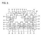
FIG. 5 is a front view of the housing, -
FIG. 6 is a rear view of the housing, -
FIG. 7 is a plan view of the housing, -
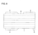
FIG. 8 is a side view of the housing, and -
FIG. 9 is a bottom view of the housing. - One preferred embodiment of the present invention is described with reference to
FIGS. 1 to 9 . A connector according to this embodiment is smaller than usual, includes ahousing 10 and one or moreterminal fittings 90 and is connectable with a mating housing. In the following description, sides of twohousings - The mating connector includes the
mating housing 60 made e.g. of synthetic resin. As shown inFIG. 1 , themating housing 60 includes a receptacle 61 (particularly substantially in the form of a rectangular tube), and one ormore tabs 81 of one or more respectivemale terminal fittings 80 are arranged to at least partly project into thereceptacle 61. Alock portion 62 is formed to project from (particularly the inner surface of the upper wall of) thereceptacle 61. - The
housing 10 is made e.g. of synthetic resin and includes a housing main body 11 (particularly substantially in the form of a rectangular block as a whole). As shown inFIGS. 6 and7 , at least onerecessed groove 12 is so formed at a position on the lateral (e.g. upper) surface of the housingmain body 11 particularly displaced slightly toward one lateral side from the widthwise center as to substantially extend over the entire length in forward and backward directions. Therecessed groove 12 has a width less than 1 cm. - A
lock arm 13 is arranged in therecessed groove 12 of the housingmain body 11. Thelock arm 13 particularly is composed of or comprises aleg portion 14 connected to the front end of the bottom surface of therecessed groove 12 and standing outward or upward, and anarm portion 15 extending substantially horizontally backward (or along the forward and backward directions) from the outer or upper end of theleg portion 14. The rear end of thearm portion 15 particularly reaches the vicinity of the rear end of the housingmain body 11. - A
lock projection 16 is formed to project at an intermediate part of the outer or upper surface of thearm portion 15 with respect to forward and backward directions. The upper end of thelock projection 16 particularly is arranged at the same height as or slightly lower than the upper surface of the housingmain body 11 at the opposite left and right sides of therecessed groove 12. Thus, thelock projection 16 particularly cannot be seen when viewed sideways. - In the process of connecting the two
housings lock projection 16 interferes with thelock portion 62, whereby thearm portion 15 substantially is resiliently deformed inward or downward with theleg portion 14 as a supporting point. When the twohousings lock projection 16 is arranged to be engageable with thelock portion 62 from behind and the twohousings - As also shown in
FIG. 2 , anunlocking portion 17 slightly raised is formed at a rear end portion of thearm portion 15. An unlockingrib 18 particularly substantially is formed over the entire width of the unlockingportion 17 at or near the rear end of the unlockingportion 17. One or more, preferably a pair of lateral (left and/or right) bulgingportions 19 are formed substantially along the (preferably substantially opposite) lateral edge(s) of thearm portion 15 at positions corresponding to the unlockingportion 17. Distances between the lateral edge(s) of the bulging portion(s) 19 and the side surface(s) of the recessedgroove 12 particularly are set to be smaller than the outer diameters ofwires 51 connected to theterminal fittings 90 to be described later, so as to ensure that thewires 51 are not jammed between them. - One or more, preferably a pair of lateral (left and/or right) protecting
portions 21 are formed to project at the (preferably substantially opposite) side(s) of the unlockingportion 17 at a rear end portion of the lateral (upper) surface of the housingmain body 11. One or more, preferably a pair of lateral (left and/or right) restrictingpieces 22 are formed to project inwardly (substantially toward the lock arm 13) at the inner edge(s) of front portion(s) of the (preferably both) protecting portion(s) 21. An excessive upward deformation of thearm portion 15 particularly is restricted by the contact of the bulgingportions 19 with the restrictingpieces 22. - The entire lateral (upper) surfaces of the protecting
portions 21 particularly substantially are flat and/or arranged higher than that of the unlocking portion 17 (excluding the unlocking rib 18) and/or substantially at the same height position as the unlockingrib 18. An unlocking space is formed adjacent to the protecting portion(s) 21 (preferably between the both protecting portions 21) and/or above (or outside of) the lateral (upper) surface of the unlocking portion 17 (excluding the unlocking rib 18). Upon separating the twohousings arm portion 15 inwardly or downwardly while engaging the claw of the fingertip with the unlockingrib 18, whereby thelock projection 16 is disengaged from thelock portion 62 to effect unlocking. - One or more, preferably a pair of lateral (left and/or right) lateral (e.g. upper)
guide projections 23 for guiding insertion of the housingmain body 11 into thereceptacle 61 are formed to substantially extend in forward and backward directions at (preferably substantially opposite widthwise end portions of the outer or upper surface of) the housingmain body 11. The front ends of the (upper)guide projections 23 are arranged slightly behind that of the housingmain body 11 and/or include one or more vertical surfaces substantially extending outwardly or in a vertical direction. The rear ends of theupper guide projections 23 are arranged in a central or intermediate part of the housingmain body 11 with respect to forward and backward directions and/or include one or more inclined surfaces sloped inward or downward toward the back side. The entire upper surfaces of the bothupper guide projections 23 particularly are substantially flat and/or arranged substantially at the same height position as the outer (upper) surfaces of the protectingportions 21. If being placed in a vertically inverted posture on a flat surface, thehousing 10 is supported substantially horizontally without being shaken by the protectingportions 21 and the bothupper guide projections 23. - As also shown in
FIG. 9 , one or more, preferably a pair of lateral (left and/or right)lower guide projections 24 are formed (preferably substantially at opposite widthwise end portions of) the outer or lower surface of the housingmain body 11. The bothlower guide projections 24 particularly have substantially the same shape and dimensions as the bothupper guide projections 23 and/or are in a vertically symmetrical positional relationship with the bothupper guide projections 23. At least onelower rib 25 is formed to extend in a width direction at the rear end of the lower surface of the housingmain body 11. The bottom end of thelower rib 25 particularly is arranged substantially at the same height position as those of the bothlower guide projections 24. If being placed on a horizontal surface, thehousing 10 is supported substantially horizontally without being shaken by thelower rib 25 and the bothlower guide projections 24. - Further, one or more, preferably a plurality of
cavities 26 are formed to penetrate the housingmain body 11 substantially in forward and backward directions. Therespective cavities 26 are arranged in one or more levels e.g. in two upper and lower levels. Out of these, thecavities 26 in the upper level are divided at the opposite left and right sides of the recessedgroove 12. The one or moreterminal fittings 90 are to be at least partly inserted into therespective cavities 26 from an insertion side, preferably substantially from behind. - Each terminal fitting 90 is integrally or unitarily formed by applying bending, folding and/or embossing and the like to an electrically conductive (particularly metal) plate and includes a box or tubular portion 91 (particularly substantially in the form of a rectangular or polygonal tube) and a wire connection portion (particularly comprising a
barrel portion 92 continuous with and behind thebox portion 91 and in the form of an open barrel) behind the box ortubular portion 91. The wire connection portion is to be connected with thewire 51 particularly by thebarrel portion 92 being crimped and connected to an end portion of thewire 51. As the twohousings more tabs 81 are to be at least partly inserted into the box ortubular portions 91 from front and the properly insertedtabs 81 come into resilient contact withresilient contact pieces 93 resiliently deformably formed in or at the box ortubular portions 91 to connect theterminal fittings - One or
more stabilizers 94, particularly an upper and alower stabilizers 94, are formed to project adjacent to or at a rear end portion of thebox portion 91. One or more guidinggrooves 27, particularly a pair of upper and lower guidinggrooves 27, are formed substantially along eachcavity 26 in the housingmain body 11, and the one ormore stabilizers 94 are to be slidably inserted into the one or more respective guidinggrooves 27. Bysuch stabilizers 94, insertion of the terminal fitting 90 into thecavity 26 is guided and/or erroneous insertion of the terminal fitting 90 into thecavity 26 is prevented. Further, the box ortubular portion 91 particularly is formed with a lockinghole 96 engageable with a lockinglance 30 to be described later by cutting and bending thestabilizer 94. Alternatively, the lockinglance 30 may engage a rear portion of the box ortubular portion 91 for locking purposes. - The resiliently
deformable locking lance 30 is formed at an inner surface of eachcavity 26 in the housingmain body 11. As shown inFIG. 3 , each lockinglance 30 particularly is cantilever shaped and/or is composed of or comprises a lancemain body 31 substantially extending forward while particularly being thickened at an intermediate part of the lateral or lower surface of an inner wall of thecavity 26 with respect to forward and backward directions, and alance projection 32 projecting from or close to a leading end portion of the inner or upper surface of the lancemain body 31. As also shown inFIG. 4 , thelower guiding groove 27 is formed to substantially extend in forward and backward directions at one lateral edge of a base end part of the lancemain body 31. The front surface of thelance projection 32 serves as a lockingsurface 33 particularly slightly overhanging forward and is engageable with the front edge of the lockinghole 96 in the box ortubular portion 91 and/or with a rear edge of the box ortubular portion 91. The rear surface of thelance projection 32 particularly serves as a guidingslope 34 inclined inward or upward toward the front, so that the terminal fitting 90 being inserted into thecavity 26 smoothly slides thereon. - A front portion (particularly a substantially front half) of the lower inner surface of each
cavity 26 is at a position slightly lower or more outward than a rear portion (particularly a substantially rear half) thereof, thereby forming adeformation space 35 for the lockinglance 30 between this recessed or lowered (lower) inner surface and a leading end portion of the outer or lower surface of the lancemain body 31. Thedeformation space 35 forms an opening in the front surface of the housingmain body 11. As shown inFIG. 5 , one or moresloped portions 36 gradually widened toward the front surface are formed at opening edge portions of the one ormore cavities 26 and/or those of thedeformation spaces 35 in the front surface of the housingmain body 11. - The housing
main body 11 is formed with one or more, preferably a pair of lateral (left and/or right)side plates 37 which partition between thedeformation space 35 and thecavity 26 located thereabove. When the terminal fitting 90 is properly inserted into thecavity 26, one or more lateral portions (particularly substantially opposite widthwise end portions) of the outer or lower surface of thebox portion 91 are supported from outside or below by the (both) side plate(s) 37. Particularly, between the bothside plates 37, amold removal hole 38 is formed due to removal of a mold for forming the front ends of the lancemain body 31 and thelance projection 32. Themold removal hole 38 forms an opening in the front surface of the housingmain body 11 and permits thecavity 26 and thedeformation space 35 to vertically communicate. - At the base end part of the locking
lance 30, avertical wall surface 41 substantially continuous with the lower surface of the lancemain body 31 and/or that of thedeformation space 35 is formed to substantially face thedeformation space 35. Arecess 42 is formed for the lockinglance 30 in a lower part of thewall surface 41 of the base end part of each lockinglance 30. Therecess 42 particularly has a substantially rectangular cross section and/or is a narrow and long hole extending backward from thewall surface 41 within width and length ranges of the lockinglance 30. The rear end of therecess 42 particularly is located before the front ends of the lower guidinggrooves 27. - A (particularly shallow)
groove portion 43 is so formed in the lower surface of eachdeformation space 35 in the housingmain body 11 as to extend over at least part of, preferably over the substantially entire length of thedeformation space 35. Thegroove portion 43 is formed upon forming a bottom end portion of therecess 42, substantially continuous with the front end of therecess 42, and forms an opening in the front surface of the housingmain body 11 while cutting off the slopedportion 36 of thedeformation space 35. A sink of the base end part of the thickenedlocking lance 30 is prevented by such arecess 42. - The connector according to this embodiment is structured as described above, and functions and effects thereof are described next.
- The
terminal fitting 90 is at least partly inserted into thecavity 26 of thehousing 10 preferably substantially from behind. In the inserting process, the box ortubular portion 91 of the terminal fitting 90 slides on the guidingslope 34 of thelance projection 32 and the lancemain body 31 is resiliently deformed substantially toward the deformation space 35 (outward or downward) with the base end thereof as a supporting point. When the terminal fitting 90 is properly inserted into thecavity 26, thelance projection 32 is fitted into the lockinghole 96 or engages a rear portion of the box ortubular portion 91 and, accordingly, the lancemain body 31 resiliently at least partly returns to retain and/or accommodate the terminal fitting 90 in thecavity 26. - Subsequently, the two
housings housings lock projection 16 of thelock arm 13 is resiliently engaged with thelock portion 62 as shown inFIG. 1 to hold the twohousings more tabs 81 are inserted to proper depths into the one or more box ortubular portions 91 to electrically connect theterminal fittings housings housing 10 can be at least partly inserted into thereceptacle 61 of themating housing 60 while the one ormore protecting portions 21 and/or thelower rib 25 are gripped by fingers. When the twohousings portions 21 are arranged near the front end of thereceptacle 61. - This connector is a non-waterproof connector including no sealing member. However, water may run between connection surfaces (front surfaces) of the two
housings cavities 26 of thehousing 10 and deposit on theterminal fittings 90 when the twohousings 10 60 are in the connected state. However, according to this embodiment, even if water enters thedeformation space 35 along the connection surfaces of the twohousings recess 42 until reaching the terminal fitting 90 after entering therecess 42 from thegroove portion 43. Therefore, a creepage distance to the terminal fitting 90 becomes longer, wherefore a simple waterproof structure of the connector can be realized. - Since the
recess 42 particularly is formed to substantially extend in forward and backward directions as an inserting direction of the terminal fitting 90, the creepage distance becomes even longer to improve a waterproof property. Further, since therecess 42 particularly is formed within the width range of the lockinglance 30, weakening of the base end part of the lockinglance 30 can be avoided to ensure a smooth resilient deformation of the lockinglance 30. - Accordingly, to provide a connector with an improved operability particularly with a simple waterproof structure, a
deformation space 35 for alocking lance 30 is formed to make an opening in the front surface of ahousing 10, and awall surface 41 of a base end part of the lockinglance 30 is located at a back side of thedeformation space 35. In the process of inserting a terminal fitting 90 into acavity 26, the lockinglance 30 is resiliently deformed toward thedeformation space 35 with a base end thereof as a supporting point. When the terminal fitting 90 is properly inserted into thecavity 26, the lockinglance 30 resiliently at least partly returns to retain the terminal fitting 90 in thecavity 26. Arecess 42 particularly is formed in thewall surface 41 of the base end portion of the lockinglance 30. - The present invention is not limited to the above described and illustrated embodiment. For example, the following embodiments are also included in the technical scope of the present invention.
- (1) The recesses may be formed between adjacent locking lances.
- (2) The recesses may have an arbitrary shape, e.g. a circular cross sectional shape.
- (3) A retainer (front retainer, side retainer or back retainer) may be mounted into the housing and the terminal fittings may be doubly locked by the retainer and the locking lances.
- (4) The present invention is also applicable to waterproof type connectors in which a sealing member is mounted in a housing.
-
- 10
- housing
- 26
- cavity
- 30
- locking lance
- 35
- deformation space
- 41
- wall surface
- 42
- recess
- 90
- terminal fitting
Claims (9)
- A connector, comprising:a housing (10) including at least one cavity (26) into which at least one terminal fitting (90) is at least partly insertable,at least one resiliently deformable locking lance (30) formed to project from an inner surface of the cavity (26), andat least one deformation space (35) for the locking lance (30) which space forms an opening in an outer surface of the housing (10), a wall surface (41) of a base end part of the locking lance (30) being located at a back side of the deformation space (35),the locking lance (30) being resiliently deformed toward the deformation space (35) with a base end thereof as a supporting point in the process of inserting the terminal fitting (90) into the cavity (26) while resiliently at least partly returning to retain the terminal fitting (90) in the cavity (26) when the terminal fitting (90) is properly inserted into the cavity (26),wherein at least one recess (42) is formed in the wall surface (41) of the base end part of the locking lance (30).
- A connector according to claim 1, wherein the recess (42) is formed to substantially extend in an inserting direction of the terminal fitting (90).
- A connector according to any one of the preceding claims, wherein the recess (42) is formed within the width of the locking lance (30).
- A connector according to any one of the preceding claims, wherein a groove portion (43) is so formed in the deformation space (35) as to extend over at least part of, preferably over the substantially entire length of the deformation space (35).
- A connector according to claim 4, wherein the groove portion (43) is formed upon forming a portion of the recess (42), substantially continuous with the front end of the recess (42), and forms an opening in the front surface of the housing (10) preferably while cutting off a sloped portion (36) of the deformation space (35).
- A connector according to any one of the preceding claims, wherein one or more sloped portions (36) gradually widened toward the front surface are formed at an opening edge portion of the cavity (26) and/or at an opening edge of the deformation space (35) in the front surface of the housing (10).
- A connector according to any one of the preceding claims, wherein the housing (10) is formed with at least one side plate (37) which at least partly partitions between the deformation space (35) and the cavity (26) located adjacent to it.
- A connector according to claim 7, wherein, when the terminal fitting (90) is properly inserted into the cavity (26), the terminal fitting (90) is supported by the side plate (37).
- A connector according to any one of the preceding claims, wherein, when the terminal fitting (90) is properly inserted into the cavity (26), a lance projection (32) of the locking lance (30) is at least partly fitted into a locking hole (96) of the terminal fitting (90) and/or engages a rear portion of a box or tubular portion (91) of the terminal fitting (90) and, accordingly, the locking lance (30) retains the terminal fitting (90) in the cavity (26).
Applications Claiming Priority (1)
| Application Number | Priority Date | Filing Date | Title |
|---|---|---|---|
| JP2009285083A JP5454121B2 (en) | 2009-12-16 | 2009-12-16 | connector |
Publications (1)
| Publication Number | Publication Date |
|---|---|
| EP2337158A1 true EP2337158A1 (en) | 2011-06-22 |
Family
ID=43303833
Family Applications (1)
| Application Number | Title | Priority Date | Filing Date |
|---|---|---|---|
| EP10014666A Withdrawn EP2337158A1 (en) | 2009-12-16 | 2010-11-16 | Connector |
Country Status (4)
| Country | Link |
|---|---|
| US (1) | US8210873B2 (en) |
| EP (1) | EP2337158A1 (en) |
| JP (1) | JP5454121B2 (en) |
| CN (1) | CN102157835B (en) |
Families Citing this family (15)
| Publication number | Priority date | Publication date | Assignee | Title |
|---|---|---|---|---|
| JP5397338B2 (en) * | 2010-07-21 | 2014-01-22 | 住友電装株式会社 | Connector manufacturing method |
| JP5629530B2 (en) * | 2010-08-23 | 2014-11-19 | 矢崎総業株式会社 | connector |
| JP5682061B2 (en) * | 2010-12-21 | 2015-03-11 | 矢崎総業株式会社 | connector |
| JP5757426B2 (en) * | 2012-03-28 | 2015-07-29 | 住友電装株式会社 | connector |
| JP5737216B2 (en) * | 2012-03-28 | 2015-06-17 | 住友電装株式会社 | connector |
| JP5956282B2 (en) * | 2012-08-10 | 2016-07-27 | 矢崎総業株式会社 | Terminal mounting structure |
| US9033736B2 (en) * | 2013-05-07 | 2015-05-19 | J.S.T. Corporation | Electrical connector with maximized circuit-to-circuit isolation distance |
| JP2017188279A (en) * | 2016-04-05 | 2017-10-12 | 住友電装株式会社 | connector |
| US9780477B1 (en) * | 2016-06-01 | 2017-10-03 | Lear Corporation | Box terminal with insertion limiter |
| CN107618458B (en) * | 2016-07-14 | 2021-10-22 | 矢崎(中国)投资有限公司 | Connector and internal signal circuit terminal |
| JP6769354B2 (en) * | 2017-03-13 | 2020-10-14 | 株式会社オートネットワーク技術研究所 | Terminal unit and connector |
| JP2019083641A (en) * | 2017-10-31 | 2019-05-30 | 株式会社デンソー | Vehicle rotary electric machine |
| US10446968B1 (en) * | 2018-05-08 | 2019-10-15 | Delphi Technologies, Llc | Connector assembly with lock reinforcement feature |
| CN109193241B (en) * | 2018-10-08 | 2020-08-18 | 浙江众邦机电科技有限公司 | Connector terminal plastic part |
| JP7424247B2 (en) * | 2020-08-26 | 2024-01-30 | 住友電装株式会社 | connector |
Citations (4)
| Publication number | Priority date | Publication date | Assignee | Title |
|---|---|---|---|---|
| EP1104051A2 (en) * | 1999-11-29 | 2001-05-30 | Yazaki Corporation | Connector |
| US6322391B1 (en) * | 1999-09-06 | 2001-11-27 | Yazaki Corporation | Double locking connector |
| US20050095909A1 (en) * | 2003-10-30 | 2005-05-05 | Sumitomo Wiring Systems, Ltd. | Connector and resin molding method therefor |
| JP2009231077A (en) | 2008-03-24 | 2009-10-08 | Sumitomo Wiring Syst Ltd | Connector |
Family Cites Families (5)
| Publication number | Priority date | Publication date | Assignee | Title |
|---|---|---|---|---|
| JPS5657486U (en) * | 1979-10-12 | 1981-05-18 | ||
| EP0378845B1 (en) * | 1988-12-28 | 1994-11-30 | The Whitaker Corporation | Electrical connector housing assembly |
| CN2196336Y (en) * | 1994-07-21 | 1995-05-03 | 淄博多星电器总厂 | Power source connector |
| US6790081B2 (en) * | 2002-05-08 | 2004-09-14 | Corning Gilbert Inc. | Sealed coaxial cable connector and related method |
| US7695315B2 (en) * | 2006-11-20 | 2010-04-13 | Tyco Electronics Corporation | Stacked electrical connector with terminal assurance mechanism |
-
2009
- 2009-12-16 JP JP2009285083A patent/JP5454121B2/en active Active
-
2010
- 2010-11-16 EP EP10014666A patent/EP2337158A1/en not_active Withdrawn
- 2010-12-03 US US12/959,675 patent/US8210873B2/en active Active
- 2010-12-09 CN CN201010586532.XA patent/CN102157835B/en active Active
Patent Citations (4)
| Publication number | Priority date | Publication date | Assignee | Title |
|---|---|---|---|---|
| US6322391B1 (en) * | 1999-09-06 | 2001-11-27 | Yazaki Corporation | Double locking connector |
| EP1104051A2 (en) * | 1999-11-29 | 2001-05-30 | Yazaki Corporation | Connector |
| US20050095909A1 (en) * | 2003-10-30 | 2005-05-05 | Sumitomo Wiring Systems, Ltd. | Connector and resin molding method therefor |
| JP2009231077A (en) | 2008-03-24 | 2009-10-08 | Sumitomo Wiring Syst Ltd | Connector |
Also Published As
| Publication number | Publication date |
|---|---|
| CN102157835A (en) | 2011-08-17 |
| US20110143588A1 (en) | 2011-06-16 |
| CN102157835B (en) | 2014-03-19 |
| JP2011129297A (en) | 2011-06-30 |
| JP5454121B2 (en) | 2014-03-26 |
| US8210873B2 (en) | 2012-07-03 |
Similar Documents
| Publication | Publication Date | Title |
|---|---|---|
| EP2337158A1 (en) | Connector | |
| EP1560298B1 (en) | A divided connector and connector assembly | |
| EP1923962B1 (en) | A connector and method of preassembling it | |
| US6948978B2 (en) | Connector and a method of assembling such connector | |
| US8708739B2 (en) | Connector | |
| US7938694B2 (en) | Connector terminal and connector with the connector terminal | |
| US7938695B2 (en) | Terminal fitting | |
| US7722414B2 (en) | Connector having separately made lance housing and retainer | |
| EP2375507B1 (en) | Terminal fitting | |
| EP1983618A2 (en) | A connector | |
| US20150222040A1 (en) | Connector terminal | |
| US9028277B2 (en) | Terminal locking structure in connector housing | |
| US20120295493A1 (en) | Terminal fitting | |
| CN102447185A (en) | Connector | |
| US9614314B2 (en) | Connector with a deflectable locking lance exposed on an outer surface of a housing | |
| EP1986288B1 (en) | A shorting terminal, a connector and an assembling method therefor | |
| US7306486B2 (en) | Connector | |
| EP1959520A2 (en) | A connector and an assembling method therefor | |
| EP2056408B1 (en) | An electrical terminal fitting and forming method therefor | |
| EP2325950B1 (en) | A connector | |
| EP1801926B1 (en) | A connetor and connector assembly | |
| CN105098434B (en) | Electrical connector | |
| US11728589B2 (en) | Connector | |
| US9407040B2 (en) | Connector with functional portion projecting from side surface of connector hosing and terminal accommodating chamber in the functional portion | |
| JP2006164585A (en) | Connector |
Legal Events
| Date | Code | Title | Description |
|---|---|---|---|
| PUAI | Public reference made under article 153(3) epc to a published international application that has entered the european phase |
Free format text: ORIGINAL CODE: 0009012 |
|
| AK | Designated contracting states |
Kind code of ref document: A1 Designated state(s): AL AT BE BG CH CY CZ DE DK EE ES FI FR GB GR HR HU IE IS IT LI LT LU LV MC MK MT NL NO PL PT RO RS SE SI SK SM TR |
|
| AX | Request for extension of the european patent |
Extension state: BA ME |
|
| 17P | Request for examination filed |
Effective date: 20110609 |
|
| 17Q | First examination report despatched |
Effective date: 20111125 |
|
| GRAP | Despatch of communication of intention to grant a patent |
Free format text: ORIGINAL CODE: EPIDOSNIGR1 |
|
| INTG | Intention to grant announced |
Effective date: 20160210 |
|
| STAA | Information on the status of an ep patent application or granted ep patent |
Free format text: STATUS: THE APPLICATION IS DEEMED TO BE WITHDRAWN |
|
| 18D | Application deemed to be withdrawn |
Effective date: 20160621 |