EP1986185A1 - Disque d'enregistrement magnétique doté de motifs servo identiques formés sur chaque surface de disque par un modèle maître unique et lecteur de disque utilisant le disque - Google Patents
Disque d'enregistrement magnétique doté de motifs servo identiques formés sur chaque surface de disque par un modèle maître unique et lecteur de disque utilisant le disque Download PDFInfo
- Publication number
- EP1986185A1 EP1986185A1 EP08250621A EP08250621A EP1986185A1 EP 1986185 A1 EP1986185 A1 EP 1986185A1 EP 08250621 A EP08250621 A EP 08250621A EP 08250621 A EP08250621 A EP 08250621A EP 1986185 A1 EP1986185 A1 EP 1986185A1
- Authority
- EP
- European Patent Office
- Prior art keywords
- servo
- disk
- fields
- pattern
- generally
- Prior art date
- Legal status (The legal status is an assumption and is not a legal conclusion. Google has not performed a legal analysis and makes no representation as to the accuracy of the status listed.)
- Ceased
Links
- 230000005291 magnetic effect Effects 0.000 title claims abstract description 36
- 238000001514 detection method Methods 0.000 claims abstract description 11
- 239000000696 magnetic material Substances 0.000 claims description 18
- 238000000034 method Methods 0.000 claims description 13
- 239000000463 material Substances 0.000 claims description 8
- 238000005070 sampling Methods 0.000 abstract description 5
- 101150020445 CYLC1 gene Proteins 0.000 description 16
- 102100036233 Cylicin-1 Human genes 0.000 description 16
- 230000008569 process Effects 0.000 description 8
- 238000004422 calculation algorithm Methods 0.000 description 6
- HHNFORCFJOVQNF-UHFFFAOYSA-N cyl-1 Chemical compound N1C(=O)C(CCCCCC(=O)C2OC2)NC(=O)C2CCCN2C(=O)C(C(C)CC)NC(=O)C1CC1=CC=C(OC)C=C1 HHNFORCFJOVQNF-UHFFFAOYSA-N 0.000 description 6
- 239000000758 substrate Substances 0.000 description 5
- WANLLPADDCXPGO-WMKJBNATSA-N (6r,9s,12s)-3-[(2s)-butan-2-yl]-6-[(4-methoxyphenyl)methyl]-9-[6-(oxiran-2-yl)-6-oxohexyl]-1,4,7,10-tetrazabicyclo[10.4.0]hexadecane-2,5,8,11-tetrone Chemical compound C([C@@H]1C(=O)NC(C(N2CCCC[C@H]2C(=O)N[C@@H](CCCCCC(=O)C2OC2)C(=O)N1)=O)[C@@H](C)CC)C1=CC=C(OC)C=C1 WANLLPADDCXPGO-WMKJBNATSA-N 0.000 description 4
- 101100117391 Arabidopsis thaliana DPB2 gene Proteins 0.000 description 4
- 101150080636 CYLC2 gene Proteins 0.000 description 4
- WANLLPADDCXPGO-UHFFFAOYSA-N Cyl-2 Natural products N1C(=O)C(CCCCCC(=O)C2OC2)NC(=O)C2CCCCN2C(=O)C(C(C)CC)NC(=O)C1CC1=CC=C(OC)C=C1 WANLLPADDCXPGO-UHFFFAOYSA-N 0.000 description 4
- 102100024257 Cylicin-2 Human genes 0.000 description 4
- 101100441847 Oryza sativa subsp. japonica CYL2 gene Proteins 0.000 description 4
- 238000001459 lithography Methods 0.000 description 4
- 238000012986 modification Methods 0.000 description 4
- 230000004048 modification Effects 0.000 description 4
- 101100025691 Arabidopsis thaliana NAGLU gene Proteins 0.000 description 3
- 101100441845 Oryza sativa subsp. japonica CYL1 gene Proteins 0.000 description 3
- 230000006870 function Effects 0.000 description 3
- 230000005415 magnetization Effects 0.000 description 3
- 230000008859 change Effects 0.000 description 2
- 239000011248 coating agent Substances 0.000 description 2
- 238000000576 coating method Methods 0.000 description 2
- 238000004590 computer program Methods 0.000 description 2
- 238000013500 data storage Methods 0.000 description 2
- 238000010586 diagram Methods 0.000 description 2
- 238000005516 engineering process Methods 0.000 description 2
- 238000000059 patterning Methods 0.000 description 2
- 238000004544 sputter deposition Methods 0.000 description 2
- 238000012546 transfer Methods 0.000 description 2
- BYHQTRFJOGIQAO-GOSISDBHSA-N 3-(4-bromophenyl)-8-[(2R)-2-hydroxypropyl]-1-[(3-methoxyphenyl)methyl]-1,3,8-triazaspiro[4.5]decan-2-one Chemical compound C[C@H](CN1CCC2(CC1)CN(C(=O)N2CC3=CC(=CC=C3)OC)C4=CC=C(C=C4)Br)O BYHQTRFJOGIQAO-GOSISDBHSA-N 0.000 description 1
- 102100036601 Aggrecan core protein Human genes 0.000 description 1
- 101100064323 Arabidopsis thaliana DTX47 gene Proteins 0.000 description 1
- 101000840469 Arabidopsis thaliana Isochorismate synthase 1, chloroplastic Proteins 0.000 description 1
- 101150026676 SID1 gene Proteins 0.000 description 1
- 108091006419 SLC25A12 Proteins 0.000 description 1
- 108091006418 SLC25A13 Proteins 0.000 description 1
- 230000004308 accommodation Effects 0.000 description 1
- 238000004364 calculation method Methods 0.000 description 1
- 238000007796 conventional method Methods 0.000 description 1
- 238000012937 correction Methods 0.000 description 1
- 238000013461 design Methods 0.000 description 1
- 238000000609 electron-beam lithography Methods 0.000 description 1
- 238000002955 isolation Methods 0.000 description 1
- 230000005381 magnetic domain Effects 0.000 description 1
- 238000004519 manufacturing process Methods 0.000 description 1
- 239000011159 matrix material Substances 0.000 description 1
- 239000004033 plastic Substances 0.000 description 1
- 239000002985 plastic film Substances 0.000 description 1
- 229920006255 plastic film Polymers 0.000 description 1
- 230000010076 replication Effects 0.000 description 1
- 238000012552 review Methods 0.000 description 1
- 239000007787 solid Substances 0.000 description 1
- 230000003068 static effect Effects 0.000 description 1
- 238000003860 storage Methods 0.000 description 1
- 230000000699 topical effect Effects 0.000 description 1
- 230000007704 transition Effects 0.000 description 1
Images


Classifications
-
- G—PHYSICS
- G11—INFORMATION STORAGE
- G11B—INFORMATION STORAGE BASED ON RELATIVE MOVEMENT BETWEEN RECORD CARRIER AND TRANSDUCER
- G11B20/00—Signal processing not specific to the method of recording or reproducing; Circuits therefor
- G11B20/10—Digital recording or reproducing
- G11B20/12—Formatting, e.g. arrangement of data block or words on the record carriers
-
- G—PHYSICS
- G11—INFORMATION STORAGE
- G11B—INFORMATION STORAGE BASED ON RELATIVE MOVEMENT BETWEEN RECORD CARRIER AND TRANSDUCER
- G11B5/00—Recording by magnetisation or demagnetisation of a record carrier; Reproducing by magnetic means; Record carriers therefor
- G11B5/86—Re-recording, i.e. transcribing information from one magnetisable record carrier on to one or more similar or dissimilar record carriers
- G11B5/865—Re-recording, i.e. transcribing information from one magnetisable record carrier on to one or more similar or dissimilar record carriers by contact "printing"
-
- B—PERFORMING OPERATIONS; TRANSPORTING
- B82—NANOTECHNOLOGY
- B82Y—SPECIFIC USES OR APPLICATIONS OF NANOSTRUCTURES; MEASUREMENT OR ANALYSIS OF NANOSTRUCTURES; MANUFACTURE OR TREATMENT OF NANOSTRUCTURES
- B82Y10/00—Nanotechnology for information processing, storage or transmission, e.g. quantum computing or single electron logic
-
- G—PHYSICS
- G11—INFORMATION STORAGE
- G11B—INFORMATION STORAGE BASED ON RELATIVE MOVEMENT BETWEEN RECORD CARRIER AND TRANSDUCER
- G11B21/00—Head arrangements not specific to the method of recording or reproducing
- G11B21/02—Driving or moving of heads
-
- G—PHYSICS
- G11—INFORMATION STORAGE
- G11B—INFORMATION STORAGE BASED ON RELATIVE MOVEMENT BETWEEN RECORD CARRIER AND TRANSDUCER
- G11B21/00—Head arrangements not specific to the method of recording or reproducing
- G11B21/02—Driving or moving of heads
- G11B21/10—Track finding or aligning by moving the head ; Provisions for maintaining alignment of the head relative to the track during transducing operation, i.e. track following
-
- G—PHYSICS
- G11—INFORMATION STORAGE
- G11B—INFORMATION STORAGE BASED ON RELATIVE MOVEMENT BETWEEN RECORD CARRIER AND TRANSDUCER
- G11B5/00—Recording by magnetisation or demagnetisation of a record carrier; Reproducing by magnetic means; Record carriers therefor
- G11B5/48—Disposition or mounting of heads or head supports relative to record carriers ; arrangements of heads, e.g. for scanning the record carrier to increase the relative speed
- G11B5/58—Disposition or mounting of heads or head supports relative to record carriers ; arrangements of heads, e.g. for scanning the record carrier to increase the relative speed with provision for moving the head for the purpose of maintaining alignment of the head relative to the record carrier during transducing operation, e.g. to compensate for surface irregularities of the latter or for track following
- G11B5/596—Disposition or mounting of heads or head supports relative to record carriers ; arrangements of heads, e.g. for scanning the record carrier to increase the relative speed with provision for moving the head for the purpose of maintaining alignment of the head relative to the record carrier during transducing operation, e.g. to compensate for surface irregularities of the latter or for track following for track following on disks
- G11B5/59688—Servo signal format patterns or signal processing thereof, e.g. dual, tri, quad, burst signal patterns
-
- G—PHYSICS
- G11—INFORMATION STORAGE
- G11B—INFORMATION STORAGE BASED ON RELATIVE MOVEMENT BETWEEN RECORD CARRIER AND TRANSDUCER
- G11B5/00—Recording by magnetisation or demagnetisation of a record carrier; Reproducing by magnetic means; Record carriers therefor
- G11B5/74—Record carriers characterised by the form, e.g. sheet shaped to wrap around a drum
- G11B5/743—Patterned record carriers, wherein the magnetic recording layer is patterned into magnetic isolated data islands, e.g. discrete tracks
-
- G—PHYSICS
- G11—INFORMATION STORAGE
- G11B—INFORMATION STORAGE BASED ON RELATIVE MOVEMENT BETWEEN RECORD CARRIER AND TRANSDUCER
- G11B5/00—Recording by magnetisation or demagnetisation of a record carrier; Reproducing by magnetic means; Record carriers therefor
- G11B5/74—Record carriers characterised by the form, e.g. sheet shaped to wrap around a drum
- G11B5/82—Disk carriers
-
- G—PHYSICS
- G11—INFORMATION STORAGE
- G11B—INFORMATION STORAGE BASED ON RELATIVE MOVEMENT BETWEEN RECORD CARRIER AND TRANSDUCER
- G11B5/00—Recording by magnetisation or demagnetisation of a record carrier; Reproducing by magnetic means; Record carriers therefor
- G11B5/48—Disposition or mounting of heads or head supports relative to record carriers ; arrangements of heads, e.g. for scanning the record carrier to increase the relative speed
- G11B5/58—Disposition or mounting of heads or head supports relative to record carriers ; arrangements of heads, e.g. for scanning the record carrier to increase the relative speed with provision for moving the head for the purpose of maintaining alignment of the head relative to the record carrier during transducing operation, e.g. to compensate for surface irregularities of the latter or for track following
- G11B5/596—Disposition or mounting of heads or head supports relative to record carriers ; arrangements of heads, e.g. for scanning the record carrier to increase the relative speed with provision for moving the head for the purpose of maintaining alignment of the head relative to the record carrier during transducing operation, e.g. to compensate for surface irregularities of the latter or for track following for track following on disks
- G11B5/59633—Servo formatting
- G11B5/59655—Sector, sample or burst servo format
Definitions
- This invention relates generally to a magnetic recording disk with pre-patterned servo patterns formed with a master template, and a magnetic recording disk drive having a servo control system operable with the servo patterns.
- Each recording surface on the disks is a continuous layer of magnetic material that becomes formed into concentric data tracks containing the magnetically recorded data bits when the recording head writes on the magnetic material.
- Each disk surface also includes a fixed, pre-recorded pattern of servo sectors that can not be written over by the recording heads and that are used to position the heads to the desired data tracks and maintain the heads on the data tracks.
- the conventional method of generating the pattern of servo sectors is by "servo-writing" the pattern on a track-by-track basis, either with a special write head and servo-writer or with the production recording head in the disk drive. Because this is a time-consuming and therefore expensive process, other methods for generating the servo patterns have been proposed.
- CMT contact magnetic duplication or transfer
- ML magnetic printing or magnetic lithography
- a "master" template is used that contains regions or islands of soft (low-coercivity) magnetic material in a pattern corresponding to the servo pattern that is to be transferred to the disk.
- the CMT master template is typically a rigid substrate or a rigid substrate with a plastic film formed on it, as described in U.S. Patents 6,347,016 B1 and 6,433,944 B1 ; and by Ishida, T. et al., "Magnetic Printing Technology-Application to HDD", IEEE Transactions on Magnetics, Vol 39, No. 2, March 2003, pp 628-632 .
- Patent 6,791,774 B1 describes a CMT template and process for forming servo patterns in perpendicular magnetic recording disks.
- Magnetic lithography (ML) using a flexible master template is described in U.S. Patent 6,798,590 B2 , assigned to the same assignee as this application, and by Bandic et al., "Magnetic lithography for servowriting applications using flexible magnetic masks nanofabricated on plastic substrates", Microsystems Technology , DOI 10.1007/s00542-006-0287-8.
- the CMT process for forming servo patterns is applicable not only to conventional "continuous" magnetic media wherein the concentric data tracks are formed in the continuous layer of magnetic material by the recording heads, but also to "discrete track” media.
- each data track consists of continuous magnetic material, but the individual data tracks are separated by nonmagnetic guard bands.
- the CMT process may be used to form not only the servo patterns but also the discrete tracks.
- Patterned magnetic media has been proposed to replace conventional continuous magnetic media to increase the data storage density in disk drives.
- the magnetic material on the disk surface is patterned into small isolated data islands such that there is a single magnetic domain in each island or "bit".
- the magnetic moment of the regions between the islands must be destroyed or substantially reduced so as to render these regions essentially nonmagnetic.
- the patterned media may be fabricated so that that there is no magnetic material in the regions between the islands.
- Patterned media can be produced by replication from a master template via nanoimprinting. The nanoimprinting process forms not only the isolated data islands in the data tracks, but also the servo patterns.
- Nanoimprinting In nanoimprinting a master mold or template replicates a topographic pattern onto a polymeric resist coating on the disk substrate, followed by sputter deposition of magnetic material over the pattern. Nanoimprinting of patterned media is described by Bandic et al., "Patterned magnetic media: impact of nanoscale patterning on hard disk drives", Solid State Technology S7+ Suppl. S, SEP 2006 ; and by Terris et al., “TOPICAL REVIEW: Nanofabricated and self-assembled magnetic structures as data storage media", J. Phys. D: Appl. Phys. 38 (2005) R199-R222 .
- the servo pattern on the back surface of the disks is not identical to, but is rather the mirror image of, the servo pattern on the front surface of the disks.
- the master template can be very expensive and require several days to fabricate because it is typically generated by relatively costly and slow e-beam lithography equipment.
- What is needed is a magnetic recording disk with identical servo patterns on front and back surfaces, and a disk drive with a servo control system that can operate with the identical servo patterns, so that a single master template can be used to form the servo patterns on both sides of the disk.
- the invention is a magnetic recording disk with identical pre-patterned servo patterns on its front and back surfaces and a disk drive with a servo control system that can operate with the identical servo patterns.
- the servo patterns on each disk surface may be pre-patterned with a single master template, resulting in the identical pattern on each disk surface.
- the servo sectors on the two disk surfaces can form identical patterns of angularly spaced arcuate-shaped lines that extend generally radially across the data tracks.
- the arcuate-shaped lines on one surface generally replicate the path of the recording head as it is moved across the data tracks by the rotary actuator, so that there is a constant sampling rate of the servo sectors on the front surface regardless of radial position of the head.
- the arcuate-shaped lines on the other surface i.e., the back surface
- the servo control processor calculates a timing adjustment from an estimate of the radial position of the head. This timing adjustment is then used to adjust the time to open a time window to allow detection of the servo sectors on the back surface.
- the servo sectors on the two disk surfaces can form identical patterns of angularly spaced straight lines that extend radially across the data tracks.
- the straight radial lines do not replicate the path of the recording head on either surface, so the servo sampling rate is not constant but varies with radial position of the head on each surface.
- the servo control processor calculates a timing adjustment from an estimate of the radial position of the head. This timing adjustment, which is one-half the timing adjustment required for the first embodiment, is then used to adjust the time to open a time window to allow detection of the servo sectors on each surface.
- the order of the servo fields in the servo sectors on the back surface will be the reverse of the order on the first surface.
- there is no change to the servo fields so the servo fields on the back surface are read in the opposite order, stored in memory and then decoded.
- servo sectors with substantially symmetric servo fields are used, so the order in which the servo fields is read is the same for the front and back surfaces.
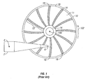
- Fig. 1 is a schematic of a disk drive with a rotary actuator and a rigid magnetic recording disk having pre-patterned servo sectors formed on a first or "front" surface.
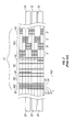
- Fig. 2 is an expanded view of a portion of a typical servo sector and portions of three data tracks of the disk shown in Fig. 1 .
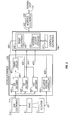
- Fig. 3 is a block diagram of a disk drive servo control system showing the modification for use with this invention.
- Figs. 4A and 4B show the comparison of the servo patterns on the front ( Fig. 4A ) and back ( Fig. 4B ) surfaces of a prior art disk.
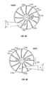
- Figs. 5A and 5B show the identical servo patterns of the front surface ( Fig. 5A ) and back surface ( Fig. 5B ) of one embodiment of a disk according to this invention.
- Fig. 6 is an illustration of typical disk drive geometry.
- Fig. 7 is a graph of timing adjustment as a function of radius, relative to zero timing adjustment at the inner radius (r ID ), for a disk surface with straight-line servo sectors.
- Fig. 8 is a view of a portion of a servo sector according to this invention with substantially symmetric servo fields.
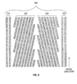
- Fig. 9 is a view of a portion of a servo sector according to this invention with substantially symmetric servo fields for use with a phase-based servo system (also called a timing-based servo system).
- phase-based servo system also called a timing-based servo system
- Fig. 1 illustrates a disk drive with a rotary actuator 2 and a rigid magnetic recording disk 10 having pre-patterned servo sectors 18 formed on a first or "front" surface 11.
- the disk 10 rotates in the direction 102 about a central axis 100.
- the front surface 11 has an annular data band 12 which is defined by an inside diameter (ID) 14 and an outside diameter (OD) 16.
- ID inside diameter
- OD outside diameter
- the portions of the data band between the servo sectors 18 are used for the storage of user data and contain circular data tracks, with each data track being typically divided into physical data sectors.
- the rotary actuator 2 rotates about pivot 4 and supports a read/write head 6 at its end. As the actuator 2 rotates, the head 6 follows a generally arcuate path between ID 14 and OD 16.
- the servo sectors 18 are not formed by conventional servowriting but by a patterning process using a master template.
- CMT contact magnetic transfer
- ML magnetic lithography
- a magnetic mask serves as the master template.
- nanoimprinting a master template replicates a topographic pattern onto a polymeric resist coating on the disk substrate, followed by sputter deposition of magnetic material over the pattern.
- the servo sectors 18 form a pattern of angularly spaced arcuate lines that extend generally radially from ID 14 to OD 16. The arcuate shape of the servo sectors matches the arcuate path of head 6.
- the head 6 reads or writes data on a selected one of a number of concentric circular data tracks located between the ID 14 and OD 16 of the annular data band 12. To accurately read or write data from a selected track, the head 6 is required to be maintained over the centerline of the track. Accordingly, each time one of the servo sectors 18 passes beneath the head 6, the head 6 detects discrete magnetized servo blocks in the position error signal (PES) field in the servo sector. A PES is generated and used by the disk drive's head positioning control system to move the head 6 towards the track centerline. Thus, during a complete rotation of the disk 10, the head 6 is continually maintained over the track centerline by servo information from the servo blocks in successive angularly spaced servo sectors 18.
- PES position error signal
- FIG. 2 An expanded top view of a typical servo sector 18 and portions of three data tracks is shown in Fig. 2 .
- the three data tracks 20, 22, 24 are shown in outline. If the disk 10 is the type with a continuous layer of magnetic recording material in the data portions of surface 11, then the tracks 20, 22, 24 are continuous tracks whose radial width is defined generally by the head 6 when it records on the continuous recording layer. If the disk 10 is the type with discrete tracks, then the tracks 20, 22, 24 would contain continuous recording material along the tracks but the tracks would be separated from each other by nonmagnetic guard bands. If the disk 10 is the type with patterned media, then the tracks 20, 22, 24 would each contain discrete islands of magnetizable material.
- All of the shaded portions of Fig. 2 represent discrete servo blocks magnetized in the same direction. They may all be magnetized in the same direction horizontally, i.e., in the plane parallel to the plane of the paper in Fig. 2 , if the disk drive is designed for longitudinal or horizontal magnetic recording, or perpendicularly, i.e., into or out of the plane of the paper, if the disk drive is for perpendicular magnetic recording. It is also possible that every other shaded region in Fig. 2 might have opposite polarity, with the unshaded regions being nonmagnetic, which improves the signal quality of the servo pattern, as described in application 11/149,028, published as US20060279871 A1 and assigned to the same assignee as this application.
- the non-shaded portions of Fig. 2 represent regions that are magnetized in the opposite direction from the magnetization of the servo blocks because they retain this opposite magnetization from a DC magnetization process prior to the CMT process. If the servo sectors 18 are formed by nanoimprinting then the non-shaded portions of Fig. 2 represent nonmagnetic regions, i.e. either regions of nonmagnetic material or regions of magnetic material generally incapable of being magnetized by the write head.
- Servo field 30 is an automatic gain control (AGC) field of blocks 31-35 that are used to measure the amplitude of the signal and adjust the provide gain for the subsequently read servo blocks.
- Servo field 40 is sector identification (SID) field, also called a servo timing mark or STM field, to provide a timing mark to establish start/stop timing windows for subsequent servo blocks.
- Servo field 50 is a track identification (TID), also called the cylinder or CYL field because the tracks from all of the disk surfaces in a disk drive with a multiple stacked disks from a "cylinder" of tracks.
- TID track identification
- the TID field 50 contains the track number, typically Gray-coded, and determines the integer part of the radial position.
- Servo field 60 is the position error signal (PES) field, which in this example contain A, B, C, D subfields of servo blocks as part of the well-known "quad-burst" PES pattern, and are used to determine the fractional part of the radial position.
- PES position error signal
- Fig. 3 is a block diagram of the disk drive servo control system and illustrates the read/write electronics 210, servo electronics 220, interface electronics 230, and controller electronics 240.
- Read/write electronics 210 receives signals from head 6, passes servo information from the servo sectors to servo electronics 220, and passes data signals to controller electronics 240.
- Servo electronics 220 uses the servo information to produce a signal at 221 which drives actuator 2 to position the head 6.
- Interface electronics 230 communicates with a host system (not shown) over interface 231, passing data and command information, including requests from the host system for reading from or writing to the data sectors of disk 10.
- Interface electronics 230 communicates with controller electronics 240 over interface 233.
- Controller electronics 240 includes a microprocessor 241 and associated memory 242 with stored computer programs for executing various algorithms, including the control algorithm.
- the control algorithm uses a set of parameters stored in memory 242 and based on the static and dynamic characteristics of the actuator 2.
- the control algorithm is essentially a matrix multiplication algorithm, and the parameters are coefficients used in the multiplication.
- Controller electronics 240 receives a list of requested data sectors from interface electronics 230 and converts them into cylinder (i.e., track), head, and data sector numbers which uniquely identify the physical location of the desired data sectors on disk 10.
- the head and cylinder numbers are passed to servo electronics 220, which positions head 6 over the appropriate data sector on the appropriate cylinder. If the cylinder number provided to servo electronics 220 is not the same as the cylinder number over which head 6 is presently positioned, servo electronics 220 first executes a "seek" operation to move the head 6 from its present cylinder to the desired cylinder.
- the servo electronics 220 first begins executing sector computations to locate and identify the desired data sector. As servo sectors pass under head 6, each servo sector is detected. In brief, the SID is used to locate servo sectors, and a count of SIDs from a servo sector containing an index mark uniquely identifies each servo sector. SID decoder 400 receives a control input 430 from the controller electronics 240 that opens a time window for detection of the next SID. SID decoder 400 then receives a clocked data stream 211 as input from the read/write electronics 210. Once a SID has been detected, a SID found signal 420 is generated.
- the SID found signal 420 is used to adjust timing circuit 401, which controls the operating sequence for the remainder of the servo sector.
- the track identification (TID) decoder 402 receives timing information 422 from timing circuit 401, reads the signals generated by TID field 50 ( Fig. 2 ), and then passes the decoded TID information 424 to controller electronics 240.
- the controller electronics 240 uses the TID information to estimate the position and velocity of the head from a stored program of instructions represented as position and velocity estimator 245.
- servo electronics 220 Once servo electronics 220 has positioned head 6 over the appropriate cylinder, the servo fields are read by the head 6 and read/write electronics 210 inputs signals 211 to the servo electronics 220. Subsequently, PES decoder 403 captures the signals from PES field 60 ( Fig. 2 ), then passes the PES 426 to controller electronics 240. Controller electronics 240 uses the PES as input to a control algorithm to calculate the signal 428 to actuator position controller 404 to maintain the head 6 on the centerline of the desired track.
- the servo sectors 18 are shaped as an arc whose center of whose center of rotation is the pivot 4 of actuator 2. This arcuate shape for the servo sectors assures that the time interval between successive sector sectors passing the head remains fixed, regardless of which track the head is on. This simplifies the design and operation of the head-positioning servo system because a constant servo sampling rate is achieved regardless of head motion.
- Figs. 4A and 4B show the comparison of the front surface 11 ( Fig. 4A ) and back surface 11a ( Fig. 4B ) of a prior art disk 10 as the disk rotates in the direction 102.
- a single master template is used for both disk surfaces, resulting in the front and back surfaces having identical servo patterns.
- Figs. 5A and 5B show the identical servo patterns of the front surface 511 ( Fig. 5A ) and back surface 511a ( Fig. 4B ) of one embodiment of a disk 510 according to this invention.
- a comparison of the direction of curvature of the arcuate servo sectors 518 ( Fig. 5A ) with the direction of curvature of the arcuate servo sectors 518a ( Fig. 5B ) shows that the two servo patterns are identical.
- the servo sectors 518a on back surface 511 a do not have a shape that follows the arc of actuator 2, so that a constant servo sample rate will not be achieved on surface 511a. Also, because the servo patterns on surfaces 511 and 511a are identical, the order of the servo fields detected by the head 6a on back surface 511a will be the reverse of the order of the servo fields detected by the head 6 on front surface 511. Thus, in this invention, the operation of the servo control system and/or the arrangement of the fields within the servo sectors are modified.
- a timing adjustment for detection of the servo sectors is made to accommodate the pattern on back surface 511.
- Fig. 6 shows a typical disk drive geometry.
- the actuator is located at distance p between pivot 4 and disk central axis 100, and has an actuator length a, which is the distance from pivot 4 to the actuator tip RW where the head is located.
- the head on the tip of the actuator makes an arc or path Z1 across the disk from a point b1 at disk inner radius r ID to point b2 at disk outer radius r OD .
- conventional servo sectors 518 like those on front surface 511 will have curvature with radius a. It is straightforward to conclude from Fig.
- ⁇ r 60 rpm ⁇ ⁇ r 360 ⁇ ° where the angle alpha is expressed in degrees.
- Fig. 7 is plotted in Fig. 7 as a function of radius, and relative to the timing adjustment at r ID , which is assumed to be 0.
- Fig. 7 is generated based on the dimensions listed in Fig. 6 at a disk rpm of 15,000.
- timing adjustment calculator 250 which is typically computer program instructions stored in memory 242.
- the controller electronics 240 uses the estimated head position and velocity from estimator 245 to calculate the timing adjustment.
- the timing adjustment is calculated from either a lookup table or an equation generated from the data Fig. 7 , using the radius (i.e., the cylinder) where the head is located, i.e., the estimated position of the head from estimator 245.
- the controller electronics 240 uses this calculated timing adjustment to trigger SID decoder 400 to open the timing window for detection of the SID.
- servo sectors may be generally radially-directed straight lines (between b1 and b2 in Fig. 6 ).
- the servo patterns are identical on front and back surfaces.
- the order of the servo fields detected by the head on surface 511 a will be the reverse of the order on surface 511.
- the servo sectors on back surface 511a are read in the opposite order, i.e., PES, CYL, SID, AGC, and stored in memory. After the AGC is read and interpreted for servo signal amplitude, the SID is analyzed and timing is established.
- servo sectors with substantially symmetric servo fields are used, as shown in Fig. 8 .
- the order in which the servo fields is read is the same for the front and back surfaces.
- the servo fields would move in the direction indicated by arrow 102
- the servo fields would move in the direction indicated by arrow 102a.
- the servo fields are substantially symmetric about the center of the servo sector.
- the PES field is located in the center of the servo sector, with the CYL code distributed as CYL1 and CYL2 on opposite ends of the PES field.
- the complete CYL field normally contains m bits that contain actual track information and n error correction code (ECC) bits, where typically m and n have similar values.
- ECC error correction code
- the CYL field is split into two subfields (CL1 and CYL2).
- CYL1 and CYL2 may each provide partial information about the cylinder number, whereas both are needed to obtain accurate track number involving ECC as well.
- CYL1 and CYL2 can each have m+n / 2 bits. This allows enough information for long seeks.
- Identical AGC fields AGC1 and AGC2) are located at each end of the servo sector, and identical SID fields (SID1 and SID2) are located between respective AGC and CYL fields.
- the additional disk surface "overhead" is for the second SID field as well as the extra m bits of the second CYL field.
- this would result in approximately 16 bits of overhead for having two CYL fields (assuming no ECC) and about 12-16 bits for the second SID field.
- a typical servo sector may have approximately 40 bits of AGC, 12 bits of SID, 32 bits of track code, 12 bits of sector code and 48 bits of PES code, for total of approximately 144 bits.
- the additional 28-32 bits is thus approximately a 20% increase in servo overhead over the conventional servo pattern ( Fig. 2 ).
- the PES field 700 includes two symmetric sets 702, 704 of generally slanted position marks extending generally radially across multiple tracks.
- Identical start-of-field (SOF) marks 701, 703 are located on respective ends of PES field 700 and extend radially across the tracks. The time from detection of a SOF mark to detection of a slanted position mark indicates the radial position of the head.
- This type of PES field is different from the conventional quad-burst PES field 60 in Fig. 2 , and thus a different type of PES decoding system is used.
- the phase-based servo system and decoding method is well-known, as described for example in US Patents 5,689,384 ; 5,923,272 and 5,930,065 .
- the CYL fields can be encoded in additional patterns located before or after the sets 702, 704.
- the CYL fields can be encoded within the sets 702, 704 of slanted position marks by shifting pairs of position marks early or late relative to other position marks in the pattern, in a manner which does not affect the overall phase relationship between the position marks.
- An example of such encoding with timing-based patterns is described in the previously cited US patents 5,923,272 and 5,930,065 . Since this method of encoding a CYL field embeds only a single bit or a few bits within each servo sector, a complete reading of a complete CYL address requires several successive servo sectors.
Applications Claiming Priority (1)
| Application Number | Priority Date | Filing Date | Title |
|---|---|---|---|
| US11/740,289 US7652839B2 (en) | 2007-04-26 | 2007-04-26 | Magnetic recording disk with identical servo patterns formed on each disk surface by single master template and disk drive using the disk |
Publications (1)
| Publication Number | Publication Date |
|---|---|
| EP1986185A1 true EP1986185A1 (fr) | 2008-10-29 |
Family
ID=39671387
Family Applications (1)
| Application Number | Title | Priority Date | Filing Date |
|---|---|---|---|
| EP08250621A Ceased EP1986185A1 (fr) | 2007-04-26 | 2008-02-22 | Disque d'enregistrement magnétique doté de motifs servo identiques formés sur chaque surface de disque par un modèle maître unique et lecteur de disque utilisant le disque |
Country Status (9)
| Country | Link |
|---|---|
| US (1) | US7652839B2 (fr) |
| EP (1) | EP1986185A1 (fr) |
| JP (1) | JP5049177B2 (fr) |
| KR (1) | KR20080096386A (fr) |
| CN (1) | CN101295515A (fr) |
| BR (1) | BRPI0803930A2 (fr) |
| RU (1) | RU2008116550A (fr) |
| SG (1) | SG147365A1 (fr) |
| TW (1) | TW200849225A (fr) |
Families Citing this family (17)
| Publication number | Priority date | Publication date | Assignee | Title |
|---|---|---|---|---|
| JP4489031B2 (ja) * | 2006-02-17 | 2010-06-23 | 東芝ストレージデバイス株式会社 | ディスク装置補正システム、情報管理装置、原盤作製装置および原盤作製方法 |
| US7848040B2 (en) * | 2007-08-17 | 2010-12-07 | Hitachi Global Storage Technologies Netherlands B.V. | Magnetic recording disk and disk drive with amplitude-type servo fields having patterned alternating-polarity servo islands for read/write head positioning |
| US8422169B2 (en) | 2009-12-14 | 2013-04-16 | Seagate Technology Llc | Shallow trench discrete track media (DTM) and pattern transfer process |
| US9311942B2 (en) * | 2009-12-18 | 2016-04-12 | HGST Netherlands B.V. | Information storage device with multiple-use fields in servo pattern |
| US8422161B2 (en) * | 2009-12-18 | 2013-04-16 | HGST Netherlands B.V. | Information storage device with multiple-use fields in servo pattern |
| US9384779B2 (en) | 2009-12-18 | 2016-07-05 | HGST Netherlands B.V. | Information storage device with multiple-use fields in servo pattern |
| JP2011165300A (ja) * | 2010-01-12 | 2011-08-25 | Fujifilm Corp | 磁気記録媒体、該磁気記録媒体を備えた磁気記録装置および転写用担体 |
| JP5553621B2 (ja) * | 2010-01-25 | 2014-07-16 | サムスン電機ジャパンアドバンスドテクノロジー株式会社 | ディスク駆動装置 |
| US8477442B2 (en) | 2010-05-11 | 2013-07-02 | HGST Netherlands B.V. | Patterned media for self-servowriting integrated servo fields |
| US8335047B2 (en) | 2010-10-07 | 2012-12-18 | HGST Netherlands B.V. | Patterned media with offset PES servo segments with length encoded track position |
| US8363348B2 (en) | 2010-10-07 | 2013-01-29 | HGST Netherlands B.V. | Patterned media with structured PES servo segments encoding local track position |
| US8630051B2 (en) | 2011-07-06 | 2014-01-14 | HGST Netherlands B.V. | Patterned media with an alternating series of concentric servo zones and overlap zones |
| US8670207B2 (en) | 2011-07-06 | 2014-03-11 | HGST Netherlands B.V. | Servo pattern compatible with planarization constraints of patterned media and use of a single master template |
| US8625219B2 (en) * | 2011-07-06 | 2014-01-07 | HGST Netherlands B.V. | Patterned media with an alternating series of concentric servo zones and overlap zones |
| US8531794B2 (en) | 2011-07-06 | 2013-09-10 | HGST Netherlands, B.V. | Patterned media with an alternating series of concentric servo zones and overlap zones |
| US8619379B2 (en) * | 2011-07-06 | 2013-12-31 | HGST Netherlands B.V. | Patterned media with an alternating series of concentric servo zones and overlap zones |
| US8743496B2 (en) | 2011-07-06 | 2014-06-03 | HGST Netherlands B.V. | Servo pattern compatible with planarization constraints of patterned media and use of a single master template |
Citations (7)
| Publication number | Priority date | Publication date | Assignee | Title |
|---|---|---|---|---|
| US5689384A (en) | 1994-06-30 | 1997-11-18 | International Business Machines Corporation | Timing based servo system for magnetic tape systems |
| US5923272A (en) | 1997-07-08 | 1999-07-13 | International Business Machines Corporation | Serial bitstream code for timing-based servo |
| US5930065A (en) | 1997-05-16 | 1999-07-27 | International Business Machines Corporation | Timing based servo longitudinal addressing |
| US6144517A (en) * | 1993-03-04 | 2000-11-07 | Sony Corporation | Magnetic disk device and method of manufacturing same |
| US6754032B1 (en) * | 1999-10-22 | 2004-06-22 | Seagate Tech. Llc | Method and system for radial and circumferential alignment of data tracks on patterned media |
| US20060012904A1 (en) * | 2004-07-16 | 2006-01-19 | Kabushiki Kaisha Toshiba | Magnetic disk and magnetic disk device provided with the same |
| US7046476B1 (en) * | 2005-01-10 | 2006-05-16 | Hitachi Global Storage Technologies | Method apparatus and system for accessing discontinuous media tracks |
Family Cites Families (16)
| Publication number | Priority date | Publication date | Assignee | Title |
|---|---|---|---|---|
| US4912585A (en) * | 1988-04-28 | 1990-03-27 | International Business Machines Corporation | Discrete track thin film magnetic recording disk with embedded servo information |
| TW342495B (en) * | 1996-07-22 | 1998-10-11 | Matsushita Electric Ind Co Ltd | Master information carrier, method of producing the same, and method for recording master information signal on magnetic recording medium |
| JPH1050013A (ja) * | 1996-08-02 | 1998-02-20 | Fujitsu Ltd | ディスク装置のオフトラック補正方法 |
| US6018512A (en) * | 1997-11-18 | 2000-01-25 | Seagate Technology, Inc. | System and method of encoding for identifying a given surface among several identically patterned disk surfaces |
| US6433944B1 (en) * | 1998-09-25 | 2002-08-13 | Fuji Photo Film Co., Ltd. | Master carrier for magnetic transfer and method for transfer |
| US6538835B1 (en) * | 1999-02-22 | 2003-03-25 | Seagate Technology Llc | Position signal distortion compensation during a disc drive seek |
| JP2003007011A (ja) * | 2001-06-21 | 2003-01-10 | Hitachi Ltd | 磁気ディスク装置 |
| US6798590B2 (en) * | 2002-01-22 | 2004-09-28 | Hitachi Global Storage Technologies Netherlands B.V. | Method for contact magnetic transfer of servo pattern to hard magnetic recording disk |
| US7027246B2 (en) * | 2002-05-09 | 2006-04-11 | Maxtor Corporation | Method for servo pattern application on single-side processed disks in a merged state |
| JP2004213700A (ja) * | 2002-11-15 | 2004-07-29 | Fuji Electric Device Technology Co Ltd | 磁気記録媒体用マスタディスクならびに位置決め装置および方法 |
| US7511912B2 (en) * | 2002-11-22 | 2009-03-31 | Seagate Technology Llc | Writing multiple servo sector patterns to improve servo sector alignment on multiple surfaces |
| US6791774B1 (en) * | 2003-05-12 | 2004-09-14 | Hitachi Global Storage Technologies Netherlands B.V. | Contact magnetic transfer of servo pattern to rigid perpendicular magnetic recording disk |
| US7092183B2 (en) * | 2003-12-10 | 2006-08-15 | Matsushita Electric Industrial Co., Ltd. | Template pattern for improving printed media self-servo writing |
| JP2006031856A (ja) * | 2004-07-16 | 2006-02-02 | Toshiba Corp | 垂直磁気記録用のパターンドディスク媒体及び同媒体を搭載した磁気ディスクドライブ |
| JP2006318581A (ja) * | 2005-05-13 | 2006-11-24 | Tdk Corp | 情報記録媒体、記録再生装置およびスタンパー |
| US7236325B2 (en) * | 2005-06-09 | 2007-06-26 | Hitachi Global Storage Technologies Netherlands B.V. | Method for formatting a magnetic recording disk with patterned nondata islands of alternating polarity |
-
2007
- 2007-04-26 US US11/740,289 patent/US7652839B2/en not_active Expired - Fee Related
-
2008
- 2008-02-14 TW TW097105224A patent/TW200849225A/zh unknown
- 2008-02-22 EP EP08250621A patent/EP1986185A1/fr not_active Ceased
- 2008-03-06 SG SG200801864-0A patent/SG147365A1/en unknown
- 2008-03-06 CN CNA2008100820715A patent/CN101295515A/zh active Pending
- 2008-03-28 JP JP2008087303A patent/JP5049177B2/ja not_active Expired - Fee Related
- 2008-04-07 KR KR1020080032212A patent/KR20080096386A/ko not_active Application Discontinuation
- 2008-04-25 RU RU2008116550/28A patent/RU2008116550A/ru not_active Application Discontinuation
- 2008-04-28 BR BRPI0803930-5A patent/BRPI0803930A2/pt not_active IP Right Cessation
Patent Citations (7)
| Publication number | Priority date | Publication date | Assignee | Title |
|---|---|---|---|---|
| US6144517A (en) * | 1993-03-04 | 2000-11-07 | Sony Corporation | Magnetic disk device and method of manufacturing same |
| US5689384A (en) | 1994-06-30 | 1997-11-18 | International Business Machines Corporation | Timing based servo system for magnetic tape systems |
| US5930065A (en) | 1997-05-16 | 1999-07-27 | International Business Machines Corporation | Timing based servo longitudinal addressing |
| US5923272A (en) | 1997-07-08 | 1999-07-13 | International Business Machines Corporation | Serial bitstream code for timing-based servo |
| US6754032B1 (en) * | 1999-10-22 | 2004-06-22 | Seagate Tech. Llc | Method and system for radial and circumferential alignment of data tracks on patterned media |
| US20060012904A1 (en) * | 2004-07-16 | 2006-01-19 | Kabushiki Kaisha Toshiba | Magnetic disk and magnetic disk device provided with the same |
| US7046476B1 (en) * | 2005-01-10 | 2006-05-16 | Hitachi Global Storage Technologies | Method apparatus and system for accessing discontinuous media tracks |
Non-Patent Citations (2)
| Title |
|---|
| BANDIC ET AL.: "Patterned magnetic media: impact of nanoscale patterning on hard disk drives", SOLID STATE TECHNOLOGY S7+, September 2006 (2006-09-01) |
| TERRIS ET AL.: "TOPICAL REVIEW: Nanofabricated and self-assembled magnetic structures as data storage media", J PHYS. D: APPL. PHYS., vol. 38, 2005, pages R199 - R222, XP020083170, DOI: doi:10.1088/0022-3727/38/12/R01 |
Also Published As
| Publication number | Publication date |
|---|---|
| TW200849225A (en) | 2008-12-16 |
| JP2008276911A (ja) | 2008-11-13 |
| SG147365A1 (en) | 2008-11-28 |
| JP5049177B2 (ja) | 2012-10-17 |
| CN101295515A (zh) | 2008-10-29 |
| BRPI0803930A2 (pt) | 2009-06-02 |
| US20080266701A1 (en) | 2008-10-30 |
| RU2008116550A (ru) | 2009-10-27 |
| KR20080096386A (ko) | 2008-10-30 |
| US7652839B2 (en) | 2010-01-26 |
Similar Documents
| Publication | Publication Date | Title |
|---|---|---|
| US7652839B2 (en) | Magnetic recording disk with identical servo patterns formed on each disk surface by single master template and disk drive using the disk | |
| US7466506B1 (en) | Magnetic recording disk drive with head positioning servo control system for disk surfaces with identical servo patterns | |
| US6490111B1 (en) | Method and apparatus for refreshing servo patterns in a disc drive | |
| US8848310B2 (en) | Offset correction values on a data storage media | |
| US7746595B1 (en) | Disk drive comprising slanted line servo bursts having reverse polarity segments | |
| US7746594B1 (en) | Disk drive comprising slanted line servo burst sets offset radially | |
| US7675699B2 (en) | Patterned-media magnetic recording disk and disk drive with data zones having nondata regions near the zone boundaries | |
| US7911728B2 (en) | Method for servowriting a patterned-media perpendicular magnetic recording disk using position error signal (PES) alignment fields | |
| JP4299874B2 (ja) | 記録再生装置 | |
| JP4299873B2 (ja) | 記録再生装置 | |
| US20070097540A1 (en) | Disk drive having a disk medium with discrete track | |
| US8427772B2 (en) | Patterned-media magnetic recording disk drive with data island misplacement information in the servo sectors | |
| JP2006031856A (ja) | 垂直磁気記録用のパターンドディスク媒体及び同媒体を搭載した磁気ディスクドライブ | |
| JP4358067B2 (ja) | 磁気記録媒体および磁気記録装置 | |
| JP4628273B2 (ja) | 記録再生装置 | |
| US7630156B2 (en) | Magnetic recording medium, recording/reproducing apparatus, and stamper for manufacturing a magnetic recording medium | |
| US8665549B2 (en) | Method for creating burst magnitude servo patterns with unipolar bits on a magnetic media of a magnetic data recording system | |
| US20060028758A1 (en) | Magnetic recording and reproducing apparatus | |
| US20070242381A1 (en) | Magnetic recording medium and magnetic recording/reproducing device | |
| US7359133B2 (en) | Magnetic recording medium and drive apparatus therefor | |
| JP4628272B2 (ja) | 記録再生装置 | |
| US8593751B2 (en) | Patterned magnetic recording disk for multi-track recording with compensation for head skew | |
| JP2008171527A (ja) | 磁気ディスクにおけるサーボパターンの形成方法およびストレージ | |
| JP2002015418A (ja) | 磁気ディスク及び磁気ディスクの製造方法 | |
| JP2003016735A (ja) | 磁気記録媒体 |
Legal Events
| Date | Code | Title | Description |
|---|---|---|---|
| PUAI | Public reference made under article 153(3) epc to a published international application that has entered the european phase |
Free format text: ORIGINAL CODE: 0009012 |
|
| AK | Designated contracting states |
Kind code of ref document: A1 Designated state(s): AT BE BG CH CY CZ DE DK EE ES FI FR GB GR HR HU IE IS IT LI LT LU LV MC MT NL NO PL PT RO SE SI SK TR |
|
| AX | Request for extension of the european patent |
Extension state: AL BA MK RS |
|
| 17P | Request for examination filed |
Effective date: 20081028 |
|
| AKX | Designation fees paid |
Designated state(s): DE FR GB |
|
| 17Q | First examination report despatched |
Effective date: 20090603 |
|
| STAA | Information on the status of an ep patent application or granted ep patent |
Free format text: STATUS: THE APPLICATION HAS BEEN REFUSED |
|
| 18R | Application refused |
Effective date: 20121007 |