EP1985776A2 - Mécanismes de réglage pour bâches - Google Patents
Mécanismes de réglage pour bâches Download PDFInfo
- Publication number
- EP1985776A2 EP1985776A2 EP08154653A EP08154653A EP1985776A2 EP 1985776 A2 EP1985776 A2 EP 1985776A2 EP 08154653 A EP08154653 A EP 08154653A EP 08154653 A EP08154653 A EP 08154653A EP 1985776 A2 EP1985776 A2 EP 1985776A2
- Authority
- EP
- European Patent Office
- Prior art keywords
- piece
- supporting piece
- arm
- fixed piece
- articulation
- Prior art date
- Legal status (The legal status is an assumption and is not a legal conclusion. Google has not performed a legal analysis and makes no representation as to the accuracy of the status listed.)
- Withdrawn
Links
Images


Classifications
-
- E—FIXED CONSTRUCTIONS
- E04—BUILDING
- E04F—FINISHING WORK ON BUILDINGS, e.g. STAIRS, FLOORS
- E04F10/00—Sunshades, e.g. Florentine blinds or jalousies; Outside screens; Awnings or baldachins
- E04F10/02—Sunshades, e.g. Florentine blinds or jalousies; Outside screens; Awnings or baldachins of flexible canopy materials, e.g. canvas ; Baldachins
- E04F10/06—Sunshades, e.g. Florentine blinds or jalousies; Outside screens; Awnings or baldachins of flexible canopy materials, e.g. canvas ; Baldachins comprising a roller-blind with means for holding the end away from a building
- E04F10/0611—Sunshades, e.g. Florentine blinds or jalousies; Outside screens; Awnings or baldachins of flexible canopy materials, e.g. canvas ; Baldachins comprising a roller-blind with means for holding the end away from a building with articulated arms supporting the movable end of the blind for deployment of the blind
- E04F10/0618—Sunshades, e.g. Florentine blinds or jalousies; Outside screens; Awnings or baldachins of flexible canopy materials, e.g. canvas ; Baldachins comprising a roller-blind with means for holding the end away from a building with articulated arms supporting the movable end of the blind for deployment of the blind whereby the pivot axis of the articulation is perpendicular to the roller
-
- E—FIXED CONSTRUCTIONS
- E04—BUILDING
- E04F—FINISHING WORK ON BUILDINGS, e.g. STAIRS, FLOORS
- E04F10/00—Sunshades, e.g. Florentine blinds or jalousies; Outside screens; Awnings or baldachins
- E04F10/02—Sunshades, e.g. Florentine blinds or jalousies; Outside screens; Awnings or baldachins of flexible canopy materials, e.g. canvas ; Baldachins
- E04F10/06—Sunshades, e.g. Florentine blinds or jalousies; Outside screens; Awnings or baldachins of flexible canopy materials, e.g. canvas ; Baldachins comprising a roller-blind with means for holding the end away from a building
- E04F10/0637—Sunshades, e.g. Florentine blinds or jalousies; Outside screens; Awnings or baldachins of flexible canopy materials, e.g. canvas ; Baldachins comprising a roller-blind with means for holding the end away from a building with mechanisms for adjusting the inclination of the blind
-
- E—FIXED CONSTRUCTIONS
- E04—BUILDING
- E04F—FINISHING WORK ON BUILDINGS, e.g. STAIRS, FLOORS
- E04F10/00—Sunshades, e.g. Florentine blinds or jalousies; Outside screens; Awnings or baldachins
- E04F10/02—Sunshades, e.g. Florentine blinds or jalousies; Outside screens; Awnings or baldachins of flexible canopy materials, e.g. canvas ; Baldachins
- E04F10/06—Sunshades, e.g. Florentine blinds or jalousies; Outside screens; Awnings or baldachins of flexible canopy materials, e.g. canvas ; Baldachins comprising a roller-blind with means for holding the end away from a building
- E04F10/0662—Sunshades, e.g. Florentine blinds or jalousies; Outside screens; Awnings or baldachins of flexible canopy materials, e.g. canvas ; Baldachins comprising a roller-blind with means for holding the end away from a building with arrangements for fastening the blind to the building
Definitions
- This invention relates to a device for adjusting the inclination of an arm of an awning, which allows the height of the ends of the arms to be adjusted during installation.
- Some ends of these arms are attached to a fixed supporting piece, such that the union between them allows the arms to rotate around an essentially vertical axis.
- This union usually consists in a cylindrical-type articulation, in which the end of the arm is linked to a cylindrical shank that is housed in a complementary cavity made in the supporting piece, which are usually the side supports of the awning roller tube.
- the aforesaid cavity and the shank are in principle designed so that in both the furled and unfurled positions the ends are left at the same height.
- the adjusting piece not to form part of the aforesaid side supports, but to consist instead of a piece supported by two bolts, whose relative travel allows the angle of the arms to be adjusted once the arms have been fitted.
- the inclination-adjusting device of the invention for awning arms resolves the aforesaid disadvantages, in addition to presenting other advantages that will be described below.
- the device of the invention for adjusting the inclination of an arm of an awning includes a supporting piece for the arm, a fixed piece and means for adjusting and setting the position of the supporting piece in relation to the fixed piece, and is characterised in that one of the two pieces, the supporting piece or the fixed piece, includes a substantially semicylindrical recess with a substantially horizontal axis, while the other piece, the fixed piece or supporting piece, has a projection complementary to the said recess, such that the two pieces between them form an articulation.
- This articulation structure allows the articulation itself, formed of two cylindrical surfaces, to serve as an articulation allowing adjustment of the angle of projection of the arm and as a vertical support, since the vertical projection of the semicylindrical surface constitutes a support surface capable of exercising a vertical force.
- the means for adjusting and setting the position includes two bolts that join the fixed piece and the supporting piece, and two orifices made in both pieces and situated on both sides of the articulation, the dimensions of said orifices being slightly greater than the diameter of said bolts, so as to permit some play in a plane perpendicular to the axis of rotation of the articulation.
- the adjustment required is of a few degrees of rotation, or even fractions of a degree of rotation, so that the play between the parts must be the minimum that permits said rotation. Since the rotation is minimal, a minimum play between the bolts and the orifices allows the adjustment to be carried out without need to complicate the mechanism with more moving parts.
- the ends of the latter that are resting on the side of the fixed piece opposite the one on which the supporting piece rests are forced to make a lateral movement. This movement is so short, however, that it can be taken up by the tolerance in the housing provided for the bolts.
- said recess or projection is in a cavity of said fixed piece, so that in assembly position the supporting piece is partially set into the fixed piece, while the cavity permits a slight rotation movement around said axis.
- This structure means that the whole formed by fixed piece and supporting piece is very robust, since scarcely any movement in relation to each other is permitted, that is, only the few degrees or fractions of a degree necessary for carrying out adjustment of the arms.
- the supporting piece is designed to carry out the adjustment when the awning is furled, that is, when its longitudinal plane, which is essentially vertical, is oriented parallel to the rolling axis of the awning.
- the aforesaid housing is likewise oriented inwards. This means that when the arms are extended, the supporting piece, in addition to being submitted to the bending moment owing to the weight of the arm, is also subjected to a twisting moment that sets up undesirable tensions.
- the twisting distance is minimised, and therefore the twisting moment also, while the latter is distributed over the fixed piece, which is more robust, instead of being distributed over the cylindrical support and the bolts.
- the adjusting and setting means include a groove made on the supporting piece destined to house a fixing plate provided with two machined orifices arranged to receive the bolts.
- This arrangement means that the supporting piece does not have to be machined, since the fixing is carried out by means of the fixing plate, which can slide along the groove, thereby reducing unnecessary tensions. And if it does not have to be machined, the supporting piece can be obtained by parting off from an extruded aluminium profile.
- the supporting piece can be made by casting.
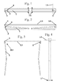
- the inclination-adjusting device of the arm of an awning 1 includes an arm supporting piece 2 on which the arm can rotate about a vertical axis. It is this rotation that takes the foldable arm of the awning from the furled awning position, as illustrated in Figures 1 and 2 , in which the arms of the awning are folded ( Figures 1 and 2 ), to the unfurled awning position, in which the arm is extended ( Figures 3 and 4 ).
- This rotation is usually through some 85°, as shown in Figure 3 , with the arm, when in the folded position, oriented along a direction parallel to the rolling axis 13 of the awning or parallel to the façade of the house, and in the extended position oriented perpendicularly to the façade of the house.
- This supporting piece 2 on which the arm rotates is usually the side cover 14 of the furlable awning unit, shown in Figure 7 , with this cover mounted perpendicular to the façade of the house.
- the rotation mechanism has a cylindrical orifice made in a projection from the cover, in collaboration with a cylindrical pin fitted on the end of the arm, both having a vertical axis 15.
- the position in the vertical direction 16 of the other end of the arm that is, the end of the arm that will ends up at medium articulation, very much depends on the orientation of the axis of the orifice and the play between that orifice and the pin of the awning arm, since the length of the arm is of the order of metres.
- a different inclination of said axis 15 of each arm leads to the heights 16 of the medium articulation of the arm being different, which gives a poor appearance that to the user looks like faulty adjustment and poor operation of the awning.
- the solution proposed by the invention is for the supporting piece 2 to be capable of varying slightly in inclination, of the order of one degree or even less, and in the vertical plane parallel to the axis 13, in such a way that the heights 16 of both arms can be adjusted and equalised.
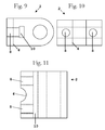
- this supporting piece 2 shown in isolation in Figures 9, 10 and 11 , to be a piece independent of the fixed piece 3, which in the invention forms part of the cover, and for both pieces to be articulated by means of a substantially horizontal axis perpendicular to the awning-roller axis.
- This articulation is given material form with a semicylindrical recess 4 made in the supporting piece and a complementary projection 5 in the fixed piece, although an inverse arrangement is also possible and is equivalent for mechanical purposes, that is, for the projection 5 to be in the supporting piece 2 and the recess 4 to be in the fixed piece 3.
- This cylindrical articulation which can be seen more clearly in Figures 5, 6 and 11 , allows the inclinations of the arms of the awning to be adjusted in folded position and to be fixed once the adjustment has been made, for which purpose the device has two bolts 7 that join the fixed piece 3 and the supporting piece 2, and two orifices 8 made in both pieces and situated on both sides of the articulation 6, as can be seen in Figure 5 , so that the desired adjustment is achieved by rotating both bolts.
- the orifices 8 for the bolts 7 of the fixed piece 3 have a diameter slightly greater than the diameter of the bolts 7.
- the orifices 8 for the bolts 7 of the supporting piece may or may not be machined, depending on the fixing system chosen.
- the projection 5 or recess 4 are situated in a cavity 9 of the fixed piece 3 in such a way that in the assembly position the supporting piece 2 is partially set into the fixed piece 3.
- This cavity also permits slight rotational play of the supporting piece, of the order of a few degrees, or even less, as shown in Figure 5 .
Landscapes
- Engineering & Computer Science (AREA)
- Architecture (AREA)
- Civil Engineering (AREA)
- Structural Engineering (AREA)
- Building Awnings And Sunshades (AREA)
Applications Claiming Priority (1)
| Application Number | Priority Date | Filing Date | Title |
|---|---|---|---|
| ES200700844U ES1065311Y (es) | 2007-04-24 | 2007-04-24 | Dispositivo de ajuste para toldos |
Publications (2)
| Publication Number | Publication Date |
|---|---|
| EP1985776A2 true EP1985776A2 (fr) | 2008-10-29 |
| EP1985776A3 EP1985776A3 (fr) | 2013-09-18 |
Family
ID=38330952
Family Applications (1)
| Application Number | Title | Priority Date | Filing Date |
|---|---|---|---|
| EP08154653.3A Withdrawn EP1985776A3 (fr) | 2007-04-24 | 2008-04-16 | Mécanismes de réglage pour bâches |
Country Status (2)
| Country | Link |
|---|---|
| EP (1) | EP1985776A3 (fr) |
| ES (1) | ES1065311Y (fr) |
Cited By (1)
| Publication number | Priority date | Publication date | Assignee | Title |
|---|---|---|---|---|
| EP2927388A1 (fr) * | 2014-04-01 | 2015-10-07 | Producciones Mitjavila, S.A. | Dispositif de fixation d'une marquise |
Families Citing this family (1)
| Publication number | Priority date | Publication date | Assignee | Title |
|---|---|---|---|---|
| ES1075721Y (es) | 2011-08-30 | 2012-02-23 | Producciones Mitjavila Sa | Dispositivo de ajuste de la inclinacion de un brazo de un toldo |
Family Cites Families (4)
| Publication number | Priority date | Publication date | Assignee | Title |
|---|---|---|---|---|
| DE3322664A1 (de) * | 1982-07-26 | 1984-02-16 | Fa. Ernst Dolenz, 1170 Wien | Verstellbare halteeinrichtung fuer arme von markisen |
| GB9405637D0 (en) * | 1994-03-22 | 1994-05-11 | Ventolite Nsb Limited | Awning mechanism |
| EP1122378A1 (fr) * | 2000-01-31 | 2001-08-08 | Turnils AB | Marquise et système de commande |
| DE20017320U1 (de) * | 2000-10-06 | 2001-01-18 | Paul Voss GmbH + Co. KG, 57413 Finnentrop | Markise mit Neigungsverstellung |
-
2007
- 2007-04-24 ES ES200700844U patent/ES1065311Y/es not_active Expired - Lifetime
-
2008
- 2008-04-16 EP EP08154653.3A patent/EP1985776A3/fr not_active Withdrawn
Cited By (1)
| Publication number | Priority date | Publication date | Assignee | Title |
|---|---|---|---|---|
| EP2927388A1 (fr) * | 2014-04-01 | 2015-10-07 | Producciones Mitjavila, S.A. | Dispositif de fixation d'une marquise |
Also Published As
| Publication number | Publication date |
|---|---|
| ES1065311U (es) | 2007-07-16 |
| EP1985776A3 (fr) | 2013-09-18 |
| ES1065311Y (es) | 2007-10-16 |
Similar Documents
| Publication | Publication Date | Title |
|---|---|---|
| US7791553B2 (en) | High wind elevation mechanism for a satellite antenna system | |
| US6273172B1 (en) | Motor operated awning | |
| EP3040500B1 (fr) | Charnière dissimulée pour une fenêtre ou une porte pivotante et fenêtre équipée de celle-ci | |
| US8752606B2 (en) | Awning with support system having articulated mounting arm | |
| US5042554A (en) | Support or guide roller device | |
| US9222227B2 (en) | Extendable screed height adjusting system with angle of attack adjustment | |
| US4479526A (en) | Structure with adjustably-tiltable articulated arms for wind up sunshade tents | |
| EP1985776A2 (fr) | Mécanismes de réglage pour bâches | |
| CA2438489A1 (fr) | Marchepied retractable pour automobile | |
| US20140042276A1 (en) | Slat support and deployment coupling | |
| CN107829511B (zh) | 一种多角度可调节的玻璃幕墙系统 | |
| US20260035979A1 (en) | Assembly consisting of a drive device, a component for closing an opening, and a guide device | |
| CN101037920B (zh) | 多功能窗 | |
| US10131448B2 (en) | Coupling module for forming an interface between the cabin of a passenger bridge and an airplane | |
| US1076310A (en) | Awning. | |
| PT1446546E (pt) | Dispositivo de articulação para um sistema de vidraça | |
| CN102066681B (zh) | 配件组 | |
| KR102100316B1 (ko) | 마감패널 설치 구조 | |
| EP1816277B1 (fr) | Auvent avec fixation réglable | |
| KR101509101B1 (ko) | 시공이 용이한 빔 조립체 | |
| CN217456202U (zh) | 一种户外观光车顶棚支架 | |
| CN100476156C (zh) | 窗或门用的配件装置 | |
| US20040163437A1 (en) | Roll forming apparatus for forming sheet material into multiple shapes | |
| CN112497544A (zh) | 一种玻璃基板切割用辅助维稳装置 | |
| CN222730875U (zh) | 一种方便幕墙平面调整的装修幕墙 |
Legal Events
| Date | Code | Title | Description |
|---|---|---|---|
| PUAI | Public reference made under article 153(3) epc to a published international application that has entered the european phase |
Free format text: ORIGINAL CODE: 0009012 |
|
| AK | Designated contracting states |
Kind code of ref document: A2 Designated state(s): AT BE BG CH CY CZ DE DK EE ES FI FR GB GR HR HU IE IS IT LI LT LU LV MC MT NL NO PL PT RO SE SI SK TR |
|
| AX | Request for extension of the european patent |
Extension state: AL BA MK RS |
|
| RIC1 | Information provided on ipc code assigned before grant |
Ipc: E04F 10/06 20060101AFI20130417BHEP |
|
| PUAL | Search report despatched |
Free format text: ORIGINAL CODE: 0009013 |
|
| AK | Designated contracting states |
Kind code of ref document: A3 Designated state(s): AT BE BG CH CY CZ DE DK EE ES FI FR GB GR HR HU IE IS IT LI LT LU LV MC MT NL NO PL PT RO SE SI SK TR |
|
| AX | Request for extension of the european patent |
Extension state: AL BA MK RS |
|
| RIC1 | Information provided on ipc code assigned before grant |
Ipc: E04F 10/06 20060101AFI20130812BHEP |
|
| STAA | Information on the status of an ep patent application or granted ep patent |
Free format text: STATUS: THE APPLICATION IS DEEMED TO BE WITHDRAWN |
|
| AKY | No designation fees paid | ||
| REG | Reference to a national code |
Ref country code: DE Ref legal event code: R108 |
|
| 18D | Application deemed to be withdrawn |
Effective date: 20131101 |
|
| REG | Reference to a national code |
Ref country code: DE Ref legal event code: R108 Effective date: 20140521 |