EP1985776A2 - Adjusting mechanism for awnings - Google Patents
Adjusting mechanism for awnings Download PDFInfo
- Publication number
- EP1985776A2 EP1985776A2 EP08154653A EP08154653A EP1985776A2 EP 1985776 A2 EP1985776 A2 EP 1985776A2 EP 08154653 A EP08154653 A EP 08154653A EP 08154653 A EP08154653 A EP 08154653A EP 1985776 A2 EP1985776 A2 EP 1985776A2
- Authority
- EP
- European Patent Office
- Prior art keywords
- piece
- supporting piece
- arm
- fixed piece
- articulation
- Prior art date
- Legal status (The legal status is an assumption and is not a legal conclusion. Google has not performed a legal analysis and makes no representation as to the accuracy of the status listed.)
- Withdrawn
Links
Images


Classifications
-
- E—FIXED CONSTRUCTIONS
- E04—BUILDING
- E04F—FINISHING WORK ON BUILDINGS, e.g. STAIRS, FLOORS
- E04F10/00—Sunshades, e.g. Florentine blinds or jalousies; Outside screens; Awnings or baldachins
- E04F10/02—Sunshades, e.g. Florentine blinds or jalousies; Outside screens; Awnings or baldachins of flexible canopy materials, e.g. canvas ; Baldachins
- E04F10/06—Sunshades, e.g. Florentine blinds or jalousies; Outside screens; Awnings or baldachins of flexible canopy materials, e.g. canvas ; Baldachins comprising a roller-blind with means for holding the end away from a building
- E04F10/0611—Sunshades, e.g. Florentine blinds or jalousies; Outside screens; Awnings or baldachins of flexible canopy materials, e.g. canvas ; Baldachins comprising a roller-blind with means for holding the end away from a building with articulated arms supporting the movable end of the blind for deployment of the blind
- E04F10/0618—Sunshades, e.g. Florentine blinds or jalousies; Outside screens; Awnings or baldachins of flexible canopy materials, e.g. canvas ; Baldachins comprising a roller-blind with means for holding the end away from a building with articulated arms supporting the movable end of the blind for deployment of the blind whereby the pivot axis of the articulation is perpendicular to the roller
-
- E—FIXED CONSTRUCTIONS
- E04—BUILDING
- E04F—FINISHING WORK ON BUILDINGS, e.g. STAIRS, FLOORS
- E04F10/00—Sunshades, e.g. Florentine blinds or jalousies; Outside screens; Awnings or baldachins
- E04F10/02—Sunshades, e.g. Florentine blinds or jalousies; Outside screens; Awnings or baldachins of flexible canopy materials, e.g. canvas ; Baldachins
- E04F10/06—Sunshades, e.g. Florentine blinds or jalousies; Outside screens; Awnings or baldachins of flexible canopy materials, e.g. canvas ; Baldachins comprising a roller-blind with means for holding the end away from a building
- E04F10/0637—Sunshades, e.g. Florentine blinds or jalousies; Outside screens; Awnings or baldachins of flexible canopy materials, e.g. canvas ; Baldachins comprising a roller-blind with means for holding the end away from a building with mechanisms for adjusting the inclination of the blind
-
- E—FIXED CONSTRUCTIONS
- E04—BUILDING
- E04F—FINISHING WORK ON BUILDINGS, e.g. STAIRS, FLOORS
- E04F10/00—Sunshades, e.g. Florentine blinds or jalousies; Outside screens; Awnings or baldachins
- E04F10/02—Sunshades, e.g. Florentine blinds or jalousies; Outside screens; Awnings or baldachins of flexible canopy materials, e.g. canvas ; Baldachins
- E04F10/06—Sunshades, e.g. Florentine blinds or jalousies; Outside screens; Awnings or baldachins of flexible canopy materials, e.g. canvas ; Baldachins comprising a roller-blind with means for holding the end away from a building
- E04F10/0662—Sunshades, e.g. Florentine blinds or jalousies; Outside screens; Awnings or baldachins of flexible canopy materials, e.g. canvas ; Baldachins comprising a roller-blind with means for holding the end away from a building with arrangements for fastening the blind to the building
Definitions
- This invention relates to a device for adjusting the inclination of an arm of an awning, which allows the height of the ends of the arms to be adjusted during installation.
- Some ends of these arms are attached to a fixed supporting piece, such that the union between them allows the arms to rotate around an essentially vertical axis.
- This union usually consists in a cylindrical-type articulation, in which the end of the arm is linked to a cylindrical shank that is housed in a complementary cavity made in the supporting piece, which are usually the side supports of the awning roller tube.
- the aforesaid cavity and the shank are in principle designed so that in both the furled and unfurled positions the ends are left at the same height.
- the adjusting piece not to form part of the aforesaid side supports, but to consist instead of a piece supported by two bolts, whose relative travel allows the angle of the arms to be adjusted once the arms have been fitted.
- the inclination-adjusting device of the invention for awning arms resolves the aforesaid disadvantages, in addition to presenting other advantages that will be described below.
- the device of the invention for adjusting the inclination of an arm of an awning includes a supporting piece for the arm, a fixed piece and means for adjusting and setting the position of the supporting piece in relation to the fixed piece, and is characterised in that one of the two pieces, the supporting piece or the fixed piece, includes a substantially semicylindrical recess with a substantially horizontal axis, while the other piece, the fixed piece or supporting piece, has a projection complementary to the said recess, such that the two pieces between them form an articulation.
- This articulation structure allows the articulation itself, formed of two cylindrical surfaces, to serve as an articulation allowing adjustment of the angle of projection of the arm and as a vertical support, since the vertical projection of the semicylindrical surface constitutes a support surface capable of exercising a vertical force.
- the means for adjusting and setting the position includes two bolts that join the fixed piece and the supporting piece, and two orifices made in both pieces and situated on both sides of the articulation, the dimensions of said orifices being slightly greater than the diameter of said bolts, so as to permit some play in a plane perpendicular to the axis of rotation of the articulation.
- the adjustment required is of a few degrees of rotation, or even fractions of a degree of rotation, so that the play between the parts must be the minimum that permits said rotation. Since the rotation is minimal, a minimum play between the bolts and the orifices allows the adjustment to be carried out without need to complicate the mechanism with more moving parts.
- the ends of the latter that are resting on the side of the fixed piece opposite the one on which the supporting piece rests are forced to make a lateral movement. This movement is so short, however, that it can be taken up by the tolerance in the housing provided for the bolts.
- said recess or projection is in a cavity of said fixed piece, so that in assembly position the supporting piece is partially set into the fixed piece, while the cavity permits a slight rotation movement around said axis.
- This structure means that the whole formed by fixed piece and supporting piece is very robust, since scarcely any movement in relation to each other is permitted, that is, only the few degrees or fractions of a degree necessary for carrying out adjustment of the arms.
- the supporting piece is designed to carry out the adjustment when the awning is furled, that is, when its longitudinal plane, which is essentially vertical, is oriented parallel to the rolling axis of the awning.
- the aforesaid housing is likewise oriented inwards. This means that when the arms are extended, the supporting piece, in addition to being submitted to the bending moment owing to the weight of the arm, is also subjected to a twisting moment that sets up undesirable tensions.
- the twisting distance is minimised, and therefore the twisting moment also, while the latter is distributed over the fixed piece, which is more robust, instead of being distributed over the cylindrical support and the bolts.
- the adjusting and setting means include a groove made on the supporting piece destined to house a fixing plate provided with two machined orifices arranged to receive the bolts.
- This arrangement means that the supporting piece does not have to be machined, since the fixing is carried out by means of the fixing plate, which can slide along the groove, thereby reducing unnecessary tensions. And if it does not have to be machined, the supporting piece can be obtained by parting off from an extruded aluminium profile.
- the supporting piece can be made by casting.
- the inclination-adjusting device of the arm of an awning 1 includes an arm supporting piece 2 on which the arm can rotate about a vertical axis. It is this rotation that takes the foldable arm of the awning from the furled awning position, as illustrated in Figures 1 and 2 , in which the arms of the awning are folded ( Figures 1 and 2 ), to the unfurled awning position, in which the arm is extended ( Figures 3 and 4 ).
- This rotation is usually through some 85°, as shown in Figure 3 , with the arm, when in the folded position, oriented along a direction parallel to the rolling axis 13 of the awning or parallel to the façade of the house, and in the extended position oriented perpendicularly to the façade of the house.
- This supporting piece 2 on which the arm rotates is usually the side cover 14 of the furlable awning unit, shown in Figure 7 , with this cover mounted perpendicular to the façade of the house.
- the rotation mechanism has a cylindrical orifice made in a projection from the cover, in collaboration with a cylindrical pin fitted on the end of the arm, both having a vertical axis 15.
- the position in the vertical direction 16 of the other end of the arm that is, the end of the arm that will ends up at medium articulation, very much depends on the orientation of the axis of the orifice and the play between that orifice and the pin of the awning arm, since the length of the arm is of the order of metres.
- a different inclination of said axis 15 of each arm leads to the heights 16 of the medium articulation of the arm being different, which gives a poor appearance that to the user looks like faulty adjustment and poor operation of the awning.
- the solution proposed by the invention is for the supporting piece 2 to be capable of varying slightly in inclination, of the order of one degree or even less, and in the vertical plane parallel to the axis 13, in such a way that the heights 16 of both arms can be adjusted and equalised.
- this supporting piece 2 shown in isolation in Figures 9, 10 and 11 , to be a piece independent of the fixed piece 3, which in the invention forms part of the cover, and for both pieces to be articulated by means of a substantially horizontal axis perpendicular to the awning-roller axis.
- This articulation is given material form with a semicylindrical recess 4 made in the supporting piece and a complementary projection 5 in the fixed piece, although an inverse arrangement is also possible and is equivalent for mechanical purposes, that is, for the projection 5 to be in the supporting piece 2 and the recess 4 to be in the fixed piece 3.
- This cylindrical articulation which can be seen more clearly in Figures 5, 6 and 11 , allows the inclinations of the arms of the awning to be adjusted in folded position and to be fixed once the adjustment has been made, for which purpose the device has two bolts 7 that join the fixed piece 3 and the supporting piece 2, and two orifices 8 made in both pieces and situated on both sides of the articulation 6, as can be seen in Figure 5 , so that the desired adjustment is achieved by rotating both bolts.
- the orifices 8 for the bolts 7 of the fixed piece 3 have a diameter slightly greater than the diameter of the bolts 7.
- the orifices 8 for the bolts 7 of the supporting piece may or may not be machined, depending on the fixing system chosen.
- the projection 5 or recess 4 are situated in a cavity 9 of the fixed piece 3 in such a way that in the assembly position the supporting piece 2 is partially set into the fixed piece 3.
- This cavity also permits slight rotational play of the supporting piece, of the order of a few degrees, or even less, as shown in Figure 5 .
Abstract
Description
- This invention relates to a device for adjusting the inclination of an arm of an awning, which allows the height of the ends of the arms to be adjusted during installation.
- Known in the art are foldable awnings that are unfurled by means of articulated arms that act upon a front bar that pulls on the front edge of the awning, causing it to unfurl.
- Some ends of these arms are attached to a fixed supporting piece, such that the union between them allows the arms to rotate around an essentially vertical axis.
- This union usually consists in a cylindrical-type articulation, in which the end of the arm is linked to a cylindrical shank that is housed in a complementary cavity made in the supporting piece, which are usually the side supports of the awning roller tube.
- The aforesaid cavity and the shank are in principle designed so that in both the furled and unfurled positions the ends are left at the same height.
- This adjustment is practically impossible to achieve, however, since any minimal error in adjustment of the axis, even of the order of fractions of a millimetre, leads to several centimetres of maladjustment of the ends of the arms, owing to the length of the latter, which is of the order of metres.
- One common solution on some models is for the adjusting piece not to form part of the aforesaid side supports, but to consist instead of a piece supported by two bolts, whose relative travel allows the angle of the arms to be adjusted once the arms have been fitted.
- However, although this system does permit a perfect adjustment, the way it is arranged sets up undesirable forces and deformations, in addition to presenting an appearance lacking in robustness, since the two bolts, in addition to carrying out their adjustment function, are subjected to a cutting force corresponding to the weight of the arms.
- Another obvious disadvantage is that between the two positions, furled and unfurled, there is an angle close to 90°, such that in one of the two positions there must be added to the cutting force a torsion force that can likewise contribute to maladjustments in the heights of the ends of the arms.
- For this reason there is clearly a need for a simple and robust inclination-adjusting mechanism that provides a solution to the problems raised.
- The inclination-adjusting device of the invention for awning arms resolves the aforesaid disadvantages, in addition to presenting other advantages that will be described below.
- The device of the invention for adjusting the inclination of an arm of an awning includes a supporting piece for the arm, a fixed piece and means for adjusting and setting the position of the supporting piece in relation to the fixed piece, and is characterised in that one of the two pieces, the supporting piece or the fixed piece, includes a substantially semicylindrical recess with a substantially horizontal axis, while the other piece, the fixed piece or supporting piece, has a projection complementary to the said recess, such that the two pieces between them form an articulation.
- This articulation structure allows the articulation itself, formed of two cylindrical surfaces, to serve as an articulation allowing adjustment of the angle of projection of the arm and as a vertical support, since the vertical projection of the semicylindrical surface constitutes a support surface capable of exercising a vertical force.
- Preferably, the means for adjusting and setting the position includes two bolts that join the fixed piece and the supporting piece, and two orifices made in both pieces and situated on both sides of the articulation, the dimensions of said orifices being slightly greater than the diameter of said bolts, so as to permit some play in a plane perpendicular to the axis of rotation of the articulation.
- The adjustment required is of a few degrees of rotation, or even fractions of a degree of rotation, so that the play between the parts must be the minimum that permits said rotation. Since the rotation is minimal, a minimum play between the bolts and the orifices allows the adjustment to be carried out without need to complicate the mechanism with more moving parts. Clearly, in acting on the bolts, the ends of the latter that are resting on the side of the fixed piece opposite the one on which the supporting piece rests are forced to make a lateral movement. This movement is so short, however, that it can be taken up by the tolerance in the housing provided for the bolts.
- Advantageously, said recess or projection is in a cavity of said fixed piece, so that in assembly position the supporting piece is partially set into the fixed piece, while the cavity permits a slight rotation movement around said axis.
- This structure means that the whole formed by fixed piece and supporting piece is very robust, since scarcely any movement in relation to each other is permitted, that is, only the few degrees or fractions of a degree necessary for carrying out adjustment of the arms.
- Further, the supporting piece is designed to carry out the adjustment when the awning is furled, that is, when its longitudinal plane, which is essentially vertical, is oriented parallel to the rolling axis of the awning. The aforesaid housing is likewise oriented inwards. This means that when the arms are extended, the supporting piece, in addition to being submitted to the bending moment owing to the weight of the arm, is also subjected to a twisting moment that sets up undesirable tensions.
- Thanks to the insetting of the supporting piece in the fixed piece, in the device of the invention the twisting distance is minimised, and therefore the twisting moment also, while the latter is distributed over the fixed piece, which is more robust, instead of being distributed over the cylindrical support and the bolts.
- More preferably, the adjusting and setting means include a groove made on the supporting piece destined to house a fixing plate provided with two machined orifices arranged to receive the bolts.
- This arrangement means that the supporting piece does not have to be machined, since the fixing is carried out by means of the fixing plate, which can slide along the groove, thereby reducing unnecessary tensions. And if it does not have to be machined, the supporting piece can be obtained by parting off from an extruded aluminium profile.
- Finally, the supporting piece can be made by casting.
- For a better understanding of the matters outlined, some drawings are attached that show, schematically and solely by way of non-restrictive example, a practical case of embodiment.
-
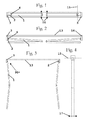
Figure 1 is a frontal view of the structure that supports the arms of the awning, when the arms are folded or drawn in. -
Figure 2 is a plan view of the position shown inFigure 1 , in which the folded position of the arms can be seen more clearly. -
Figure 3 is a plan view of another position in which the awning is unfurled. -
Figure 4 is a side view of the position shown inFigure 3 . -
Figure 5 is an elevation view of the fixed piece and supporting piece assembly, in which two fixing positions of the supporting piece can be observed. -
Figure 6 is a plan view of the assembly shown inFigure 5 . -
Figure 7 is a frontal elevation view of thefixed piece 3, which in the preferred embodiment constitutes the side cover of the awning box. -
Figure 8 is a plan view of the piece shown inFigure 7 . -
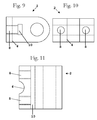
Figure 9 is a plan view of the supporting piece. -
Figure 10 is a frontal elevation view of the piece shown inFigure 9 . -
Figure 11 is a side elevation view of the piece shown inFigure 9 . - According to a preferred embodiment, the inclination-adjusting device of the arm of an
awning 1 includes anarm supporting piece 2 on which the arm can rotate about a vertical axis. It is this rotation that takes the foldable arm of the awning from the furled awning position, as illustrated inFigures 1 and 2 , in which the arms of the awning are folded (Figures 1 and 2 ), to the unfurled awning position, in which the arm is extended (Figures 3 and 4 ). - This rotation is usually through some 85°, as shown in
Figure 3 , with the arm, when in the folded position, oriented along a direction parallel to therolling axis 13 of the awning or parallel to the façade of the house, and in the extended position oriented perpendicularly to the façade of the house. - This supporting
piece 2 on which the arm rotates is usually theside cover 14 of the furlable awning unit, shown inFigure 7 , with this cover mounted perpendicular to the façade of the house. The rotation mechanism has a cylindrical orifice made in a projection from the cover, in collaboration with a cylindrical pin fitted on the end of the arm, both having avertical axis 15. - However, as noted above, the position in the
vertical direction 16 of the other end of the arm, that is, the end of the arm that will ends up at medium articulation, very much depends on the orientation of the axis of the orifice and the play between that orifice and the pin of the awning arm, since the length of the arm is of the order of metres. When the arms are extended, a different inclination ofsaid axis 15 of each arm leads to theheights 16 of the medium articulation of the arm being different, which gives a poor appearance that to the user looks like faulty adjustment and poor operation of the awning. When extended, as can be seen inFigures 3 and 4 , the difference of inclinations of the arms also leads to the ends of the arms being atdifferent heights 17, but as the front bar is of considerable length, of the order of metres, the height difference of centimetres become a perceptible angle of inclination of the front bar, although this has a negligible effect from the point of view of mechanical tensions in the awning mechanism. - The solution proposed by the invention is for the supporting
piece 2 to be capable of varying slightly in inclination, of the order of one degree or even less, and in the vertical plane parallel to theaxis 13, in such a way that theheights 16 of both arms can be adjusted and equalised. - For this purpose it is necessary, according to the invention, for this supporting
piece 2, shown in isolation inFigures 9, 10 and 11 , to be a piece independent of thefixed piece 3, which in the invention forms part of the cover, and for both pieces to be articulated by means of a substantially horizontal axis perpendicular to the awning-roller axis. This articulation is given material form with asemicylindrical recess 4 made in the supporting piece and acomplementary projection 5 in the fixed piece, although an inverse arrangement is also possible and is equivalent for mechanical purposes, that is, for theprojection 5 to be in the supportingpiece 2 and therecess 4 to be in thefixed piece 3. - This cylindrical articulation, which can be seen more clearly in
Figures 5, 6 and11 , allows the inclinations of the arms of the awning to be adjusted in folded position and to be fixed once the adjustment has been made, for which purpose the device has twobolts 7 that join thefixed piece 3 and the supportingpiece 2, and twoorifices 8 made in both pieces and situated on both sides of thearticulation 6, as can be seen inFigure 5 , so that the desired adjustment is achieved by rotating both bolts. - In the preferred embodiment, the
orifices 8 for thebolts 7 of thefixed piece 3 have a diameter slightly greater than the diameter of thebolts 7. - The
orifices 8 for thebolts 7 of the supporting piece may or may not be machined, depending on the fixing system chosen. - This can be implemented in two ways:
- In the first, the
orifices 8 of the supportingpiece 2 are threaded in order to take thebolts 7 directly, so that, preferably, the supporting piece can be made by casting and moulding. - In the second, the
orifices 8 of the supportingpiece 2 have, as in thefixed piece 3, a diameter slightly greater than that of the bolt, and are fixed into threaded orifices 12 made in a fixing plate 11 (not shown) which can slide along an opening 10 in the supportingpiece 2, so allowing the supporting piece to be made, for example, from extruded aluminium profiles. - Preferably, in the preferred embodiment described, in the adjusting device of the invention the
projection 5 orrecess 4 are situated in acavity 9 of thefixed piece 3 in such a way that in the assembly position the supportingpiece 2 is partially set into thefixed piece 3. - As can be seen in
Figures 3 and 4 , when the arms are extended their own weight, together with the weight of the awning and of the front bar, give rise to a moment applied on the articulation, which is transmitted to the supporting piece, which is then subjected to a torsion. This twisting moment can be the source of undesirable forces and deformations, and it is therefore desirable to be able to reduce it, for example by reducing the torsion distance on the supporting piece. This is achieved by allowing for acavity 9 in thefixed piece 3, as shown inFigures 5, 6 ,7 and 8 , in such a way that this cavity is perfectly adjusted to the supporting piece in the vertical direction, causing the torsion to be partially resisted by the fixed piece, which has a much larger section. - This cavity also permits slight rotational play of the supporting piece, of the order of a few degrees, or even less, as shown in
Figure 5 .
Claims (7)
- Adjusting device of the inclination of an arm of an awning (1), which includes a supporting piece (2) for said arm, a fixed piece (3) and means for adjusting and setting the position of said supporting piece (2) in relation to said fixed piece (3), characterised in that one of the two pieces, the supporting piece (2) or the fixed piece (3), has a substantially semicylindrical recess (4) with a substantially horizontal axis, and the other piece, the fixed piece (3) or supporting piece (2), has a projection (5) complementary to said recess, such that the two pieces between them form an articulation (6).
- Adjusting device according to Claim 1, characterised in that said means for adjusting and setting the position include two bolts (7) that join the fixed piece (3) and the supporting piece (2), and two orifices (8) made in both pieces and situated on both sides of the articulation (6), the dimensions of said orifices (8) being slightly greater than the diameter of said bolts (7), so as to permit some play in a plane perpendicular to the axis of rotation of the articulation (6).
- Adjusting device according to Claim 1, characterised in that said projection (5) or recess (4) is in a cavity (9) of said fixed piece (3), so that in assembly position the supporting piece (2) is partially set into said fixed piece (3) and in that said cavity (9) permits a slight rotation movement around said axis.
- Adjusting device according to Claim 2, characterised in that said means for adjusting and setting include a groove (10) made on said supporting piece (2) destined to house a fixing plate (11), said fixing plate (11) being provided with two machined orifices (12) arranged to receive said bolts (7).
- Adjusting device according to Claim 2, characterised in that the two orifices (8) made in said supporting piece are machined to receive said bolts (7).
- Adjusting device according to Claim 1, characterised in that said supporting piece (2) is a section of an extruded aluminium profile.
- Adjusting device according to Claim 1, characterised in that said supporting piece (2) is a casting.
Applications Claiming Priority (1)
| Application Number | Priority Date | Filing Date | Title |
|---|---|---|---|
| ES200700844U ES1065311Y (en) | 2007-04-24 | 2007-04-24 | FITTING ADJUSTMENT DEVICE |
Publications (2)
| Publication Number | Publication Date |
|---|---|
| EP1985776A2 true EP1985776A2 (en) | 2008-10-29 |
| EP1985776A3 EP1985776A3 (en) | 2013-09-18 |
Family
ID=38330952
Family Applications (1)
| Application Number | Title | Priority Date | Filing Date |
|---|---|---|---|
| EP08154653.3A Withdrawn EP1985776A3 (en) | 2007-04-24 | 2008-04-16 | Adjusting mechanism for awnings |
Country Status (2)
| Country | Link |
|---|---|
| EP (1) | EP1985776A3 (en) |
| ES (1) | ES1065311Y (en) |
Cited By (1)
| Publication number | Priority date | Publication date | Assignee | Title |
|---|---|---|---|---|
| EP2927388A1 (en) * | 2014-04-01 | 2015-10-07 | Producciones Mitjavila, S.A. | Supporting structure for an awning |
Families Citing this family (1)
| Publication number | Priority date | Publication date | Assignee | Title |
|---|---|---|---|---|
| ES1075721Y (en) | 2011-08-30 | 2012-02-23 | Producciones Mitjavila Sa | DEVICE FOR ADJUSTMENT OF THE INCLINATION OF A TOLDO ARM |
Citations (4)
| Publication number | Priority date | Publication date | Assignee | Title |
|---|---|---|---|---|
| DE3322664A1 (en) * | 1982-07-26 | 1984-02-16 | Fa. Ernst Dolenz, 1170 Wien | Adjustable holding device for arms of awnings |
| EP0674062A1 (en) * | 1994-03-22 | 1995-09-27 | VENTOLITE nsb LTD. | Awning mechanism |
| EP1122378A1 (en) * | 2000-01-31 | 2001-08-08 | Turnils AB | Awning assembly and control system |
| US20040016511A1 (en) * | 2000-10-06 | 2004-01-29 | Reiner Mester | Awning with inclination adjustment |
-
2007
- 2007-04-24 ES ES200700844U patent/ES1065311Y/en not_active Expired - Lifetime
-
2008
- 2008-04-16 EP EP08154653.3A patent/EP1985776A3/en not_active Withdrawn
Patent Citations (4)
| Publication number | Priority date | Publication date | Assignee | Title |
|---|---|---|---|---|
| DE3322664A1 (en) * | 1982-07-26 | 1984-02-16 | Fa. Ernst Dolenz, 1170 Wien | Adjustable holding device for arms of awnings |
| EP0674062A1 (en) * | 1994-03-22 | 1995-09-27 | VENTOLITE nsb LTD. | Awning mechanism |
| EP1122378A1 (en) * | 2000-01-31 | 2001-08-08 | Turnils AB | Awning assembly and control system |
| US20040016511A1 (en) * | 2000-10-06 | 2004-01-29 | Reiner Mester | Awning with inclination adjustment |
Cited By (1)
| Publication number | Priority date | Publication date | Assignee | Title |
|---|---|---|---|---|
| EP2927388A1 (en) * | 2014-04-01 | 2015-10-07 | Producciones Mitjavila, S.A. | Supporting structure for an awning |
Also Published As
| Publication number | Publication date |
|---|---|
| EP1985776A3 (en) | 2013-09-18 |
| ES1065311Y (en) | 2007-10-16 |
| ES1065311U (en) | 2007-07-16 |
Similar Documents
| Publication | Publication Date | Title |
|---|---|---|
| US7791553B2 (en) | High wind elevation mechanism for a satellite antenna system | |
| US6273172B1 (en) | Motor operated awning | |
| US20120180396A1 (en) | Door hinge for hidden placement between door frame and door leaf, and door provided with the door hinge | |
| US11938798B2 (en) | Openable structure for a substructure | |
| CN101187277A (en) | Articulated-quadrilateral hinge assembly with adaptable stabiliser bar for vertical-movement doors | |
| WO2006009897A3 (en) | Trailing beam suspension with alignment adjustment assembly | |
| US5042554A (en) | Support or guide roller device | |
| US9222227B2 (en) | Extendable screed height adjusting system with angle of attack adjustment | |
| US9573673B2 (en) | Slat support and deployment coupling | |
| US7275403B2 (en) | Longitudinal curvature adjustment assembly for a rain gutter roll forming machine | |
| EP1985776A2 (en) | Adjusting mechanism for awnings | |
| US20170089108A1 (en) | Recessed adjustable door hinge | |
| US10131448B2 (en) | Coupling module for forming an interface between the cabin of a passenger bridge and an airplane | |
| CN207148391U (en) | A kind of angle lenses governor motion and lens construction | |
| AU3513401A (en) | Mattress support | |
| PT1446546E (en) | A hinging device for a glazing system | |
| JP4750673B2 (en) | Sliding door suspension support device | |
| CN107829511B (en) | Glass curtain wall system with adjustable multi-angle | |
| EP1816277B1 (en) | Awning with adjustable fixing | |
| CN113008398B (en) | Mounting bracket for strip steel lower surface temperature detector and mounting method thereof | |
| CN214576480U (en) | Stand base is used in shutter installation | |
| CN220791099U (en) | Adjustable support of roller shutter, roller shutter and roller shutter | |
| KR102100316B1 (en) | Finishing panel installation structure | |
| CN220349853U (en) | Foldable support of side eave umbrella canopy | |
| CN219411579U (en) | Make shaping protection railing have stand of arbitrary direction regulatory function |
Legal Events
| Date | Code | Title | Description |
|---|---|---|---|
| PUAI | Public reference made under article 153(3) epc to a published international application that has entered the european phase |
Free format text: ORIGINAL CODE: 0009012 |
|
| AK | Designated contracting states |
Kind code of ref document: A2 Designated state(s): AT BE BG CH CY CZ DE DK EE ES FI FR GB GR HR HU IE IS IT LI LT LU LV MC MT NL NO PL PT RO SE SI SK TR |
|
| AX | Request for extension of the european patent |
Extension state: AL BA MK RS |
|
| RIC1 | Information provided on ipc code assigned before grant |
Ipc: E04F 10/06 20060101AFI20130417BHEP |
|
| PUAL | Search report despatched |
Free format text: ORIGINAL CODE: 0009013 |
|
| AK | Designated contracting states |
Kind code of ref document: A3 Designated state(s): AT BE BG CH CY CZ DE DK EE ES FI FR GB GR HR HU IE IS IT LI LT LU LV MC MT NL NO PL PT RO SE SI SK TR |
|
| AX | Request for extension of the european patent |
Extension state: AL BA MK RS |
|
| RIC1 | Information provided on ipc code assigned before grant |
Ipc: E04F 10/06 20060101AFI20130812BHEP |
|
| STAA | Information on the status of an ep patent application or granted ep patent |
Free format text: STATUS: THE APPLICATION IS DEEMED TO BE WITHDRAWN |
|
| AKY | No designation fees paid | ||
| REG | Reference to a national code |
Ref country code: DE Ref legal event code: R108 |
|
| 18D | Application deemed to be withdrawn |
Effective date: 20131101 |
|
| REG | Reference to a national code |
Ref country code: DE Ref legal event code: R108 Effective date: 20140521 |