EP1985407B1 - Method for producing steel wool and steel shot pellets - Google Patents
Method for producing steel wool and steel shot pellets Download PDFInfo
- Publication number
- EP1985407B1 EP1985407B1 EP08103593A EP08103593A EP1985407B1 EP 1985407 B1 EP1985407 B1 EP 1985407B1 EP 08103593 A EP08103593 A EP 08103593A EP 08103593 A EP08103593 A EP 08103593A EP 1985407 B1 EP1985407 B1 EP 1985407B1
- Authority
- EP
- European Patent Office
- Prior art keywords
- steel
- wire
- paring
- steel wire
- polygonal
- Prior art date
- Legal status (The legal status is an assumption and is not a legal conclusion. Google has not performed a legal analysis and makes no representation as to the accuracy of the status listed.)
- Not-in-force
Links
Images
Classifications
-
- B—PERFORMING OPERATIONS; TRANSPORTING
- B23—MACHINE TOOLS; METAL-WORKING NOT OTHERWISE PROVIDED FOR
- B23P—METAL-WORKING NOT OTHERWISE PROVIDED FOR; COMBINED OPERATIONS; UNIVERSAL MACHINE TOOLS
- B23P17/00—Metal-working operations, not covered by a single other subclass or another group in this subclass
- B23P17/04—Metal-working operations, not covered by a single other subclass or another group in this subclass characterised by the nature of the material involved or the kind of product independently of its shape
- B23P17/06—Making steel wool or the like
-
- B—PERFORMING OPERATIONS; TRANSPORTING
- B21—MECHANICAL METAL-WORKING WITHOUT ESSENTIALLY REMOVING MATERIAL; PUNCHING METAL
- B21F—WORKING OR PROCESSING OF METAL WIRE
- B21F45/00—Wire-working in the manufacture of other particular articles
Definitions
- the present invention relates to a process which is suitable for the combined production of steel wool and steel shot particles.
- Steel shot grains are used in hunting and sporting munitions.
- a larger number of shotgun grains are placed in a shotgun cartridge that further contains a propellant charge and an igniter.
- the individual shotgun grains are randomly filled in a shotgun cup, which slides during the firing through the barrel of the gun to avoid the direct contact of the shotgun grains with the inner race wall, so that the barrel is not damaged.
- the shot pellets of a shotgun should have the same size and a uniform weight as possible to obtain a regular shot image.
- the same rolled steel wires are used as starting material in other technological processes, especially for the production of steel wool.
- Steel wool is needed, for example, as an additive in brake pads.
- the thin steel chips which form such steel wool can be produced, for example, by peeling off a rolled steel wire.
- the DE 199 01 441 C1 shows a machine for producing steel wool, in which a steel wire is guided in several juxtaposed wire windings over pulleys, which are shaved with knife blades chips from the wire. This results in relatively uncontrolled attacking the knife edge on the wire, so that steel chips can be peeled off only to a predetermined residual diameter of the wire to prevent tearing of the wire. There remains inevitably a large amount of waste of steel wire, which can not be further processed into steel chips.
- the object of the present invention is thus to make the use of rolled steel wire more efficient, especially to reduce the amount of waste in the production of steel wool.
- This object is achieved by the method specified in claim 1.
- the production of steel wool is combined with the production of steel shot grains, whereby the amount of waste, which usually remains in steel wool production, can be reduced to almost zero.
- a steel wire serving as a starting material with a circular diameter is peeled off from several sides in order to give the steel wire a quadrangular or polygonal profile.
- the peeled steel chips are available as steel wool.
- the remaining steel wire with a quadrangular or polygonal cross-section is used directly in the further production process as starting material for the production of steel shot grains.
- the produced wire profile is divided into small steel wire sections, which are subsequently subjected to a rounding process until the steel wire sections have a polygonal shape.
- the energy-intensive drawing of the wire rod to increase the tensile strength can initially be dispensed with for producing the steel wool. Since it is not necessary to peel the wire rod to the smallest possible cross section, a significantly lower tensile strength is sufficient to avoid the tearing of the steel wire during the peeling process. In addition, the tensile forces on the wire can be reduced by opposing arrangement of peeling blades.
- a preferred embodiment of the method according to the invention is characterized in that the steel chips are peeled off the rolled steel wire in several layers.
- several peeling blades are arranged along the running direction of the steel wire. It is particularly expedient if in each case two opposing paring knives are combined to form a peeling step, wherein at least two peeling steps with staggering blades offset by 90 ° in the axial or longitudinal direction of the rolled steel wire are arranged one after the other. In this way, the peeling process is first started from two sides on the steel wire, while the other two sides are processed in the subsequent peeling stage.
- steel wire sections are divided with a length which is approximately equal to the circumferential diameter of the wire profile.
- the wire profile has a square cross-section by means of a corresponding arrangement of the peeling blades
- steel wire cords with a uniform edge length are present after the steel wire sections have been divided.
- these cubes are subsequently subjected to the rounding process in order to form a polygonal surface on the steel shot grains.
- the steel shot grains can be subsequently polished with high quality requirements and coated with a rust inhibitor.
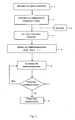
- FIG. 1 shows a flow chart of a process for the combined production of steel wool and steel shot.
- step 1 conventional steel wire of round cross-section, for example, with a diameter of 5.5 mm and a tensile strength of about 300 N / mm 2 is provided.
- step 2 steel chips are peeled off the circular steel wire on at least four sides. The peeling can be done in several layers by successively arranged peeling knife. After peeling off the steel chips, steel wool is the first process product available in step 3.
- step 4 Since the peeling of the steel chips is carried out only up to a predetermined residual diameter or a residual thickness, a four- or polygonal wire profile remains in step 4, which is preferably further processed in the ongoing process without interrupting the process.
- step 5 small steel wire sections are divided from the polygonal wire profile, preferably in a length / width ratio of 1: 1. If the wire profile delivered in step 4 has a square cross section, cube-shaped steel wire sections are present. The steel wire sections are subsequently fed in a conventional manner to a rounding process. The rounding takes place in step 6 in particular by means of an accelerating device which hurls the steel wire sections at high speed onto baffle plates. As a result of the impact of the steel wire sections on the baffle plates, the edges of the steel wire sections are deformed so that polygonal surface sections are formed. The steel wire sections go through the rounding process until the desired polygonal surface of the steel shot is reached.
- a final form can be sought in which the perpendicular distance between a spherical surface completely encompassing the steel shot grain and the polygonal face at no point is more than 20% of the diameter of this spherical surface.
- the rounding process is aborted when it is determined in step 7 that the predetermined condition for the polygonal surface has been reached.
- polygonal pellets are present as a second result of the method according to the invention.
- the method described is preferably carried out in a uniform production line, so that no intermediate storage of the polygonal wire profile after peeling the steel chips is necessary. There is essentially no waste, so that material utilization can be regarded as optimal. It is also advantageous that in addition to the same production time, which is required in the prior art for the production of steel wool, additional steel shot grains are produced, which are available as a second salable process product.
Abstract
Description
Die vorliegende Erfindung betrifft ein Verfahren, welches sich zur kombinierten Herstellung von Stahlwolle und Stahlschrotkörnern eignet.The present invention relates to a process which is suitable for the combined production of steel wool and steel shot particles.
Stahlschrotkörner werden in Jagd- und Sportwaffenmunition eingesetzt. Um Schrotmunition herzustellen, wird eine größere Anzahl von Schrotkörnern in eine Schrotpatrone eingebracht, die weiterhin eine Treibladung und einen Zünder enthält. Zumeist sind die einzelnen Schrotkörner ungeordnet in einen Schrotbecher eingefüllt, der bei der Schussabgabe durch den Lauf der Waffe gleitet, um die unmittelbare Berührung der Schrotkörner mit der Laufinnenwand zu vermeiden, damit der Lauf nicht beschädigt wird. Die Schrotkörner einer Schrotladung sollen zur Erzielung eines regelmäßigen Schussbildes möglichst die gleiche Größe und ein einheitliches Gewicht aufweisen.Steel shot grains are used in hunting and sporting munitions. To make shotgun ammunition, a larger number of shotgun grains are placed in a shotgun cartridge that further contains a propellant charge and an igniter. In most cases, the individual shotgun grains are randomly filled in a shotgun cup, which slides during the firing through the barrel of the gun to avoid the direct contact of the shotgun grains with the inner race wall, so that the barrel is not damaged. The shot pellets of a shotgun should have the same size and a uniform weight as possible to obtain a regular shot image.
Aus der
Prinzipiell dieselben Walzstahldrähte werden als Ausgangsmaterial in anderen technologischen Abläufen eingesetzt, speziell für die Herstellung von Stahlwolle. Stahlwolle wird beispielsweise als Zusatz in Bremsbelägen benötigt. Die dünnen Stahlspäne, welche derartige Stahlwolle bilden, lassen sich zum Beispiel durch Abschälen von einem Walzstahldraht herstellen. Die
Aus der Praxis ist es bekannt, zur Herstellung von Stahlwolle einen zylindrischen Walzdraht zunächst durch Ziehen im Durchmesser zu verkleinern, um dadurch die Zugfestigkeit des Stahldrahtes zu erhöhen. Bei einer Durchmesserreduzierung von beispielsweise 5,5 mm auf 3,2 mm lässt sich durch diese Methode die Zugfestigkeit von etwa 300 N/mm2 auf ca. 800 N/mm2 steigern. Nachfolgend werden von dem Stahldraht Späne abgeschält, wobei das Schälmesser nur von einer Seite am Draht angreift. Eine Effizienzerhöhung lässt sich durch Anordnung mehrer Schälmesser erreichen, die nacheinander von drei verschiedenen Seiten Späne vom zuvor gezogenen Stahldraht abschälen. Als Abfall verbleibt in diesem Fall ein im Querschnitt dreieckiger Stahldraht, der keiner weiteren Nutzung zugeführt werden kann.From practice it is known, for the production of steel wool, to first reduce a cylindrical wire rod by pulling it in diameter, thereby increasing the tensile strength of the steel wire. With a diameter reduction from, for example, 5.5 mm to 3.2 mm, this method can increase the tensile strength from about 300 N / mm 2 to about 800 N / mm 2 . Subsequently, shavings are peeled off from the steel wire, the peeling blade engaging the wire from one side only. An increase in efficiency can be achieved by arranging several paring knives, which successively peel chips from three different sides of the previously drawn steel wire. The waste in this case remains in cross section triangular steel wire that can not be used for any further purpose.
In der
In der
Die Aufgabe der vorliegenden Erfindung besteht somit darin, die Nutzung von Walzstahldraht effizienter zu gestalten, insbesondere um bei der Herstellung von Stahlwolle die Abfallmengen zu verringern.The object of the present invention is thus to make the use of rolled steel wire more efficient, especially to reduce the amount of waste in the production of steel wool.
Diese Aufgabe wird durch das im Anspruch 1 angegebene Verfahren gelöst. Für die Erfindung ist von besonderer Bedeutung, dass die Herstellung von Stahlwolle mit der Herstellung von Stahlschrotkörnern kombiniert wird, wodurch die Abfallmenge, die üblicherweise bei der Stahlwolleherstellung verbleibt, nahezu auf null reduziert werden kann. Dazu wird ein als Ausgangsmaterial dienender Stahldraht mit kreisrundem Durchmesser kontrolliert von mehreren Seiten abgeschält, um dem Stahldraht ein vier- oder mehreckiges Profil zu verleihen. Die abgeschälten Stahlspäne stehen als Stahlwolle zur Verfügung. Der verbleibende Stahldraht mit vier- oder mehreckigem Querschnitt dient im weiteren Produktionsprozess unmittelbar als Ausgangsmaterial für die Herstellung von Stahlschrotkörnern. Dazu wird das erzeugte Drahtprofil in kleine Stahldrahtabschnitte zerteilt, die nachfolgend einem Arrondierprozess unterzogen werden, bis die Stahldrahtabschnitte eine polygonale Form besitzen.This object is achieved by the method specified in
Bei der Durchführung des erfindungsgemäßen Verfahrens kann zur Herstellung der Stahlwolle zunächst auf das energieintensive Ziehen des Walzdrahtes zur Erhöhung der Zugfestigkeit verzichtet werden. Da es nicht erforderlich ist, den Walzdraht bis auf einen möglichst geringen Querschnitt abzuschälen, genügt eine deutlich geringere Zugfestigkeit, um das Reißen des Stahldrahtes während des Schälprozesses zu vermeiden. Außerdem lassen sich die Zugkräfte auf den Draht durch gegenüberliegende Anordnung von Schälmessern reduzieren.When carrying out the process according to the invention, the energy-intensive drawing of the wire rod to increase the tensile strength can initially be dispensed with for producing the steel wool. Since it is not necessary to peel the wire rod to the smallest possible cross section, a significantly lower tensile strength is sufficient to avoid the tearing of the steel wire during the peeling process. In addition, the tensile forces on the wire can be reduced by opposing arrangement of peeling blades.
Nachdem der Walzstahldraht auf mindestens vier Seiten abgeschält wurde, beispielsweise bis auf einen verbleibenden Umfangsdurchmesser von ca. 3 mm, lässt sich aus diesem mehreckigen Drahtprofil sehr einfach polygonales Stahlschrot herstellen. Das üblicherweise erforderliche Ziehen und/oder Walzen von kreisrundem Walzstahldraht entfällt, da die kurzen Stahldrahtabschnitte direkt aus dem mehreckigen Drahtprofil abgeschnitten werden können. Der erforderliche Arrondierprozess wird verkürzt, da die Zugfestigkeit des Materials nicht durch einen vorangegangenen Ziehvorgang erhöht wurde. Die für Stahlschrot erforderliche Härte ist bei herkömmlichem Stahldraht ausreichend, zumal üblicherweise eine weiche Oberfläche gewünscht ist. Im Regelfall kann damit auch der sonst übliche Wärmebehandlungsschritt zur Verringerung der Oberflächenhärte entfallen, wobei dieser bei abgewandelten Ausführungsformen trotzdem ausführbar bleibt.After the rolled steel wire has been peeled off on at least four sides, for example, up to a remaining circumference diameter of about 3 mm, it is very easy to produce polygonal steel shot from this polygonal wire profile. The usually required drawing and / or rolling of circular rolled steel wire is eliminated, since the short steel wire sections can be cut directly from the polygonal wire profile. The required rounding process is shortened because the tensile strength of the material was not increased by a previous drawing process. The hardness required for steel shot is sufficient with conventional steel wire, especially since usually a soft surface is desired. As a rule, it is therefore also possible to omit the otherwise customary heat treatment step for reducing the surface hardness, although in the case of modified embodiments this still remains feasible.
Eine bevorzugte Ausführungsform des erfindungsgemäßen Verfahrens zeichnet sich dadurch aus, dass die Stahlspäne in mehreren Lagen vom Walzstahldraht abgeschält werden. Dazu sind mehrere Schälmesser längs der Laufrichtung des Stahldrahts angeordnet. Es ist besonders zweckmäßig, wenn jeweils zwei gegenüberliegende Schälmesser zu einer Schälstufe zusammengefasst sind, wobei mindestens zwei Schälstufen mit um 90° versetzten Schälmessern in Achs- bzw. Längsrichtung des Walzstahldrahtes nacheinander angeordnet sind. Auf diese Weise wird zunächst von zwei Seiten am Stahldraht der Schälprozess gestartet, während die beiden anderen Seiten in der nachfolgenden Schälstufe bearbeitet werden.A preferred embodiment of the method according to the invention is characterized in that the steel chips are peeled off the rolled steel wire in several layers. For this purpose, several peeling blades are arranged along the running direction of the steel wire. It is particularly expedient if in each case two opposing paring knives are combined to form a peeling step, wherein at least two peeling steps with staggering blades offset by 90 ° in the axial or longitudinal direction of the rolled steel wire are arranged one after the other. In this way, the peeling process is first started from two sides on the steel wire, while the other two sides are processed in the subsequent peeling stage.
Von dem vier- oder mehreckigen Drahtprofil werden vorzugsweise Stahldrahtabschnitte mit einer Länge abgeteilt, die etwa gleich dem Umfangsdurchmesser des Drahtprofils ist.Of the four- or polygonal wire profile preferably steel wire sections are divided with a length which is approximately equal to the circumferential diameter of the wire profile.
Sofern das Drahtprofil durch entsprechende Einrichtung der Schälmesser einen quadratischen Querschnitt aufweist, liegen nach dem Abteilen der Stahldrahtabschnitte Stahldrahtwürfel mit einheitlicher Kantenlänge vor. In an sich bekannter Weise werden diese Würfel nachfolgend dem Arrondierprozess unterzogen, um eine polygonale Oberfläche an den Stahlschrotkörnern auszubilden. Die Stahlschrotkörner können bei hohen Qualitätsanforderungen nachfolgend poliert und mit einem Rostschutzmittel beschichtet werden.If the wire profile has a square cross-section by means of a corresponding arrangement of the peeling blades, steel wire cords with a uniform edge length are present after the steel wire sections have been divided. In a manner known per se, these cubes are subsequently subjected to the rounding process in order to form a polygonal surface on the steel shot grains. The steel shot grains can be subsequently polished with high quality requirements and coated with a rust inhibitor.
Weitere Vorteile, Einzelheiten und Weiterbildungen ergeben sich aus der nachfolgenden Beschreibung eines bevorzugten Ablaufs des erfindungsgemäßen Verfahrens unter Bezugnahme auf die Zeichnung. Die einzige
Im Schritt 1 wird herkömmlicher Stahldraht mit rundem Querschnitt, beispielsweise mit einem Durchmesser von 5,5 mm und einer Zugfestigkeit von etwa 300 N/mm2 bereitgestellt. Im nachfolgenden Schritt 2 werden von dem kreisrunden Stahldraht an mindestens vier Seiten Stahlspäne abgeschält. Das Abschälen kann in mehreren Lagen durch nacheinander angeordnete Schälmesser vorgenommen werden. Nach dem Abschälen der Stahlspäne steht im Schritt 3 die Stahlwolle als erstes Verfahrensprodukt zur Verfügung.In
Da das Abschälen der Stahlspäne nur bis zu einem vorgegebenen Restdurchmesser bzw. einer Restdicke ausgeführt wird, bleibt im Schritt 4 ein vier- oder mehreckiges Drahtprofil übrig, welches vorzugsweise ohne Verfahrensunterbrechung im laufenden Prozess weiter bearbeitet wird.Since the peeling of the steel chips is carried out only up to a predetermined residual diameter or a residual thickness, a four- or polygonal wire profile remains in
Im nachfolgenden Schritt 5 werden von dem mehreckigen Drahtprofil kleine Stahldrahtabschnitte abgeteilt, vorzugsweise in einem Längen/Breitenverhältnis von 1:1. Sofern das im Schritt 4 gelieferte Drahtprofil einen quadratischen Querschnitt aufweist, liegen damit würfelförmige Stahldrahtabschnitte vor. Die Stahldrahtabschnitte werden nachfolgend in an sich bekannter Weise einem Arrondierprozess zugeführt. Das Arrondieren erfolgt im Schritt 6 insbesondere mit Hilfe einer Beschleunigungsvorrichtung, welche die Stahldrahtabschnitte mit hoher Geschwindigkeit auf Prallplatten schleudert. Durch das Auftreffen der Stahldrahtabschnitte auf den Prallplatten werden die Kanten der Stahldrahtabschnitte deformiert, so dass sich polygonale Oberflächenabschnitte ausbilden. Die Stahldrahtabschnitte durchlaufen den Arrondierprozess so lange, bis die gewünschte polygonale Oberfläche des Stahlschrotkorns erreicht ist. Beispielsweise kann eine Endform angestrebt werden, bei welcher der lotrechte Abstand zwischen einer das Stahlschrotkorn vollständig umgreifenden Kugeloberfläche und der Polygonalfläche an keinem Punkt mehr als 20 % des Durchmessers dieser Kugeloberfläche beträgt. Der Arrondierprozess wird abgebrochen, wenn im Schritt 7 festgestellt wird, dass die vorgegebene Bedingung für die polygonale Oberfläche erreicht ist. Im Schritt 8 liegen als zweites Ergebnis des erfindungsgemäßen Verfahrens polygonale Schrotkörner vor.In the following
Bei Bedarf schließen sich Wärmebehandlungsschritte und Oberflächenveredlungsschritte an, um die Stahlschrotkörner an die gewünschten Einsatzzwecke anzupassen. Derartige Oberflächenbehandlungsschritte sind dem Fachmann bekannt, so dass hier auf eine detailliertere Beschreibung verzichtet wird.If necessary, heat treatment steps and surface finishing steps follow to tailor the steel shot grains to the desired applications. Such surface treatment steps are known to the person skilled in the art, so that a more detailed description is dispensed with here.
Das beschriebene Verfahren wird vorzugsweise in einer einheitlichen Fertigungsstrecke ausgeführt, so dass keine Zwischenlagerung des mehreckigen Drahtprofils nach dem Abschälen der Stahlspäne nötig ist. Es entsteht im Wesentlichen kein Abfall, so dass die Materialverwertung als optimal angesehen werden kann. Vorteilhaft ist dabei auch, dass im Wesentlichen in derselben Fertigungszeit, die im Stand der Technik für die Erzeugung von Stahlwolle benötigt wird, zusätzlich Stahlschrotkörner erzeugt werden, die als zweites verkaufsfähiges Verfahrensprodukt zur Verfügung stehen.The method described is preferably carried out in a uniform production line, so that no intermediate storage of the polygonal wire profile after peeling the steel chips is necessary. There is essentially no waste, so that material utilization can be regarded as optimal. It is also advantageous that in addition to the same production time, which is required in the prior art for the production of steel wool, additional steel shot grains are produced, which are available as a second salable process product.
Claims (9)
- A method for the manufacture of steel wool and steel shot pellets comprising the following steps:- Making available (1) a steel wire with a substantially circular diameter;- Producing a quadrangular or polygonal wire profile with a given circumferential diameter by paring off (2) steel shavings from the steel wire with paring knives that remove steel shavings along the axial direction, which paring knives attack at least four sides of the steel wire;- Making available (3) the steel shavings as steel wool;- Dividing off (5) small steel wire sections from the produced wire profile;- Rounding-off (6) the steel wire sections until they have a polygonal form;- Making available (8) the rounded-off polygonal steel wire sections as steel shot pellets.
- The method according to claim 1, characterized in that the paring off (2) of the steel shavings takes place in several layers by several successively arranged paring knives.
- The method according to claim 1 or 2, characterized in that a substantially quadratic wire profile is produced by paring off (2) steel shavings with four paring knives.
- The method according to one of claims 1 to 3, characterized in that during the paring off (2) of the steel shavings each two opposite paring knives are combined to one paring step, and that the steel wire runs through at least two paring steps successively arranged in the axial direction.
- The method according to one of claims 1 to 4, characterized in that the steel wire sections are divided off with a length approximately equal to the circumferential diameter of the wire profile from the quadratic or polygonal wire profile produced.
- The method according to one of claims 1 to 5, characterized in that the rounded-off steel shot pellets can be subjected to a thermal treatment in order to reduce surface hardness.
- The method according to one of claims 1 to 6, characterized in that the steel shot pellets are finally polished and coated with an anti-rust agent.
- The method according to one of claims 1 to 7, characterized in that rolled steel wire with a diameter > 4 mm, preferably 5.5 mm is used.
- The method according to one of claims 1 to 8, characterized in that the circumferential diameter of the quadratic or polygonal wire profile is < 3.5 mm, preferably 3.2 mm after the paring off of the steel shavings.
Applications Claiming Priority (1)
| Application Number | Priority Date | Filing Date | Title |
|---|---|---|---|
| DE102007020485A DE102007020485B3 (en) | 2007-04-27 | 2007-04-27 | Production method e.g. for steel wool and steel grain of shots, ammunition, involves deploying wired beam having circular diameter and four-wire profile is created having given diameter which can be removed along axial part |
Publications (3)
| Publication Number | Publication Date |
|---|---|
| EP1985407A2 EP1985407A2 (en) | 2008-10-29 |
| EP1985407A3 EP1985407A3 (en) | 2009-07-15 |
| EP1985407B1 true EP1985407B1 (en) | 2010-08-18 |
Family
ID=39363447
Family Applications (1)
| Application Number | Title | Priority Date | Filing Date |
|---|---|---|---|
| EP08103593A Not-in-force EP1985407B1 (en) | 2007-04-27 | 2008-04-17 | Method for producing steel wool and steel shot pellets |
Country Status (4)
| Country | Link |
|---|---|
| US (1) | US20080286469A1 (en) |
| EP (1) | EP1985407B1 (en) |
| AT (1) | ATE477880T1 (en) |
| DE (2) | DE102007020485B3 (en) |
Families Citing this family (3)
| Publication number | Priority date | Publication date | Assignee | Title |
|---|---|---|---|---|
| US8726778B2 (en) | 2011-02-16 | 2014-05-20 | Ervin Industries, Inc. | Cost-effective high-volume method to produce metal cubes with rounded edges |
| WO2012125944A1 (en) * | 2011-03-16 | 2012-09-20 | Olin Corporation | Rounded cubic shot and shotshells loaded with rounded cubic shot |
| WO2020099390A1 (en) | 2018-11-13 | 2020-05-22 | Basf Se | Catalyst bed comprising silver catalyst bodies and process for the oxidative dehydrogenation of olefinically unsaturated alcohols |
Family Cites Families (7)
| Publication number | Priority date | Publication date | Assignee | Title |
|---|---|---|---|---|
| US1598814A (en) * | 1924-02-21 | 1926-09-07 | Galvin John | Metal-shaving machine |
| US2703512A (en) * | 1951-06-22 | 1955-03-08 | Armco Steel Corp | Wire shaving apparatus |
| DE1627748A1 (en) * | 1967-03-20 | 1971-03-11 | Karl Hartmann | Method and device for the production of steel wool |
| FR2273625A1 (en) * | 1974-06-08 | 1976-01-02 | Arbed F & G Drahtwerke | YARN FOR THE MANUFACTURE OF STEEL WOOL |
| US6527880B2 (en) * | 1998-09-04 | 2003-03-04 | Darryl D. Amick | Ductile medium-and high-density, non-toxic shot and other articles and method for producing the same |
| DE19901441C1 (en) * | 1999-01-15 | 2000-05-25 | Eht Werkzeugmaschinen Gmbh | Steel wool forming machine has rollers to support wire and cutter pivotably mounted adjacent to wire run |
| DE10151585C1 (en) * | 2001-10-23 | 2003-06-12 | Baumbach Metall Gmbh & Co Kg | Wire shaping system for manufacture of polygonal-shaped steel shot for use in sporting shotguns involves rolling to square-section, cutting to form cubes and then partial rounding to make polygonal shape |
-
2007
- 2007-04-27 DE DE102007020485A patent/DE102007020485B3/en not_active Expired - Fee Related
-
2008
- 2008-04-17 EP EP08103593A patent/EP1985407B1/en not_active Not-in-force
- 2008-04-17 DE DE502008001136T patent/DE502008001136D1/en active Active
- 2008-04-17 AT AT08103593T patent/ATE477880T1/en active
- 2008-04-28 US US12/111,027 patent/US20080286469A1/en not_active Abandoned
Also Published As
| Publication number | Publication date |
|---|---|
| EP1985407A2 (en) | 2008-10-29 |
| ATE477880T1 (en) | 2010-09-15 |
| DE502008001136D1 (en) | 2010-09-30 |
| DE102007020485B3 (en) | 2008-06-12 |
| EP1985407A3 (en) | 2009-07-15 |
| US20080286469A1 (en) | 2008-11-20 |
Similar Documents
| Publication | Publication Date | Title |
|---|---|---|
| DE102008024313A1 (en) | Preconditioning surface to be coated such as inner surface of hollow cylinder, by machiningly and/or embossingly introducing undercuts and/or preforms of undercuts into the surface, and carrying out non-cutting process step with preforms | |
| DE2754563A1 (en) | METHOD AND DEVICE FOR PULLING ANGLED COLLARS THROUGH HOLES IN A METAL PLATE AND ONE OR MORE COLLARED PLATE IN THIS WAY | |
| DE1503939A1 (en) | Saw blade and process for its manufacture | |
| EP1985407B1 (en) | Method for producing steel wool and steel shot pellets | |
| DE202008006379U1 (en) | Koaxialprofil | |
| DE2607755C2 (en) | ||
| EP2964406B1 (en) | Method for producing a gun barrel having barrel flutings | |
| DE102014100711A1 (en) | Method and device for producing pipe shells and pipe shell produced therewith | |
| EP3493937B1 (en) | Harvesting knife and method for the production thereof | |
| EP3983749A1 (en) | Projectile, in particular deformation and/or partial fragmentation projectile, and method for producing a projectile | |
| DE102013102703A1 (en) | Method for producing a steel pipe with cleaning of the pipe outer wall | |
| DE2338391A1 (en) | PROCESS AND DEVICE FOR MANUFACTURING EXTRUSIONAL ROUND MATERIALS FROM STEEL OR OTHER METALLIC MATERIALS BY HOT FORMING | |
| DE4240246C2 (en) | Process for the production of a thick-walled tube of small diameter | |
| DE3008679A1 (en) | DEEP-DRAWABLE SHEET OR STRIP MADE OF NON-FERROUS METAL OR ALLOY THEREOF, ESPECIALLY MADE OF ALUMINUM, AND METHOD FOR THE PRODUCTION THEREOF | |
| DE102009019070A1 (en) | Adjustment ramp ring producing method for clutch device, involves producing ring body at adjustment ramp by cutting of pipe like semi-finished product i.e. pipe, in single ramp cutting process | |
| DE2063123A1 (en) | Heat exchanger element and manufacturing process | |
| DE1932139A1 (en) | Deep drawing steel cartridge cases | |
| DE19619034C2 (en) | Process for improving the formability in the production of components from light metal strip | |
| DE102018211380A1 (en) | Device and method for separating rod-shaped segments of the tobacco processing industry from one strand | |
| DE309101C (en) | ||
| DE102012212717A1 (en) | Roller assembly for use as bending tool for roller bending device for bending e.g. ring bending parts, has holders comprising bearing projections positioned between bending rolls, and axles or shafts supported between bending rollers | |
| DE921867C (en) | Method and device for manufacturing finned tube and finned tube | |
| DE1527290A1 (en) | Methods and devices for bending electrically conductive long materials | |
| DE102021100363A1 (en) | Process for the production of bullets | |
| DE102015101390A1 (en) | Method and device for producing friction torques transmitting sheet metal rings |
Legal Events
| Date | Code | Title | Description |
|---|---|---|---|
| PUAI | Public reference made under article 153(3) epc to a published international application that has entered the european phase |
Free format text: ORIGINAL CODE: 0009012 |
|
| AK | Designated contracting states |
Kind code of ref document: A2 Designated state(s): AT BE BG CH CY CZ DE DK EE ES FI FR GB GR HR HU IE IS IT LI LT LU LV MC MT NL NO PL PT RO SE SI SK TR |
|
| AX | Request for extension of the european patent |
Extension state: AL BA MK RS |
|
| PUAL | Search report despatched |
Free format text: ORIGINAL CODE: 0009013 |
|
| AK | Designated contracting states |
Kind code of ref document: A3 Designated state(s): AT BE BG CH CY CZ DE DK EE ES FI FR GB GR HR HU IE IS IT LI LT LU LV MC MT NL NO PL PT RO SE SI SK TR |
|
| AX | Request for extension of the european patent |
Extension state: AL BA MK RS |
|
| 17P | Request for examination filed |
Effective date: 20091229 |
|
| AKX | Designation fees paid |
Designated state(s): AT BE BG CH CY CZ DE DK EE ES FI FR GB GR HR HU IE IS IT LI LT LU LV MC MT NL NO PL PT RO SE SI SK TR |
|
| GRAP | Despatch of communication of intention to grant a patent |
Free format text: ORIGINAL CODE: EPIDOSNIGR1 |
|
| GRAS | Grant fee paid |
Free format text: ORIGINAL CODE: EPIDOSNIGR3 |
|
| GRAA | (expected) grant |
Free format text: ORIGINAL CODE: 0009210 |
|
| AK | Designated contracting states |
Kind code of ref document: B1 Designated state(s): AT BE BG CH CY CZ DE DK EE ES FI FR GB GR HR HU IE IS IT LI LT LU LV MC MT NL NO PL PT RO SE SI SK TR |
|
| REG | Reference to a national code |
Ref country code: GB Ref legal event code: FG4D Free format text: NOT ENGLISH |
|
| REG | Reference to a national code |
Ref country code: CH Ref legal event code: EP |
|
| REG | Reference to a national code |
Ref country code: IE Ref legal event code: FG4D Free format text: LANGUAGE OF EP DOCUMENT: GERMAN |
|
| REF | Corresponds to: |
Ref document number: 502008001136 Country of ref document: DE Date of ref document: 20100930 Kind code of ref document: P |
|
| REG | Reference to a national code |
Ref country code: RO Ref legal event code: EPE |
|
| REG | Reference to a national code |
Ref country code: NL Ref legal event code: VDEP Effective date: 20100818 |
|
| LTIE | Lt: invalidation of european patent or patent extension |
Effective date: 20100818 |
|
| PG25 | Lapsed in a contracting state [announced via postgrant information from national office to epo] |
Ref country code: NO Free format text: LAPSE BECAUSE OF FAILURE TO SUBMIT A TRANSLATION OF THE DESCRIPTION OR TO PAY THE FEE WITHIN THE PRESCRIBED TIME-LIMIT Effective date: 20101118 Ref country code: LT Free format text: LAPSE BECAUSE OF FAILURE TO SUBMIT A TRANSLATION OF THE DESCRIPTION OR TO PAY THE FEE WITHIN THE PRESCRIBED TIME-LIMIT Effective date: 20100818 Ref country code: FI Free format text: LAPSE BECAUSE OF FAILURE TO SUBMIT A TRANSLATION OF THE DESCRIPTION OR TO PAY THE FEE WITHIN THE PRESCRIBED TIME-LIMIT Effective date: 20100818 |
|
| PG25 | Lapsed in a contracting state [announced via postgrant information from national office to epo] |
Ref country code: PL Free format text: LAPSE BECAUSE OF FAILURE TO SUBMIT A TRANSLATION OF THE DESCRIPTION OR TO PAY THE FEE WITHIN THE PRESCRIBED TIME-LIMIT Effective date: 20100818 Ref country code: HR Free format text: LAPSE BECAUSE OF FAILURE TO SUBMIT A TRANSLATION OF THE DESCRIPTION OR TO PAY THE FEE WITHIN THE PRESCRIBED TIME-LIMIT Effective date: 20100818 Ref country code: IS Free format text: LAPSE BECAUSE OF FAILURE TO SUBMIT A TRANSLATION OF THE DESCRIPTION OR TO PAY THE FEE WITHIN THE PRESCRIBED TIME-LIMIT Effective date: 20101218 Ref country code: SI Free format text: LAPSE BECAUSE OF FAILURE TO SUBMIT A TRANSLATION OF THE DESCRIPTION OR TO PAY THE FEE WITHIN THE PRESCRIBED TIME-LIMIT Effective date: 20100818 Ref country code: CY Free format text: LAPSE BECAUSE OF FAILURE TO SUBMIT A TRANSLATION OF THE DESCRIPTION OR TO PAY THE FEE WITHIN THE PRESCRIBED TIME-LIMIT Effective date: 20100818 Ref country code: BG Free format text: LAPSE BECAUSE OF FAILURE TO SUBMIT A TRANSLATION OF THE DESCRIPTION OR TO PAY THE FEE WITHIN THE PRESCRIBED TIME-LIMIT Effective date: 20101118 |
|
| REG | Reference to a national code |
Ref country code: IE Ref legal event code: FD4D |
|
| PG25 | Lapsed in a contracting state [announced via postgrant information from national office to epo] |
Ref country code: SE Free format text: LAPSE BECAUSE OF FAILURE TO SUBMIT A TRANSLATION OF THE DESCRIPTION OR TO PAY THE FEE WITHIN THE PRESCRIBED TIME-LIMIT Effective date: 20100818 Ref country code: NL Free format text: LAPSE BECAUSE OF FAILURE TO SUBMIT A TRANSLATION OF THE DESCRIPTION OR TO PAY THE FEE WITHIN THE PRESCRIBED TIME-LIMIT Effective date: 20100818 Ref country code: GR Free format text: LAPSE BECAUSE OF FAILURE TO SUBMIT A TRANSLATION OF THE DESCRIPTION OR TO PAY THE FEE WITHIN THE PRESCRIBED TIME-LIMIT Effective date: 20101119 Ref country code: LV Free format text: LAPSE BECAUSE OF FAILURE TO SUBMIT A TRANSLATION OF THE DESCRIPTION OR TO PAY THE FEE WITHIN THE PRESCRIBED TIME-LIMIT Effective date: 20100818 |
|
| PG25 | Lapsed in a contracting state [announced via postgrant information from national office to epo] |
Ref country code: DK Free format text: LAPSE BECAUSE OF FAILURE TO SUBMIT A TRANSLATION OF THE DESCRIPTION OR TO PAY THE FEE WITHIN THE PRESCRIBED TIME-LIMIT Effective date: 20100818 Ref country code: IE Free format text: LAPSE BECAUSE OF FAILURE TO SUBMIT A TRANSLATION OF THE DESCRIPTION OR TO PAY THE FEE WITHIN THE PRESCRIBED TIME-LIMIT Effective date: 20100818 |
|
| PG25 | Lapsed in a contracting state [announced via postgrant information from national office to epo] |
Ref country code: SK Free format text: LAPSE BECAUSE OF FAILURE TO SUBMIT A TRANSLATION OF THE DESCRIPTION OR TO PAY THE FEE WITHIN THE PRESCRIBED TIME-LIMIT Effective date: 20100818 Ref country code: IT Free format text: LAPSE BECAUSE OF FAILURE TO SUBMIT A TRANSLATION OF THE DESCRIPTION OR TO PAY THE FEE WITHIN THE PRESCRIBED TIME-LIMIT Effective date: 20100818 Ref country code: EE Free format text: LAPSE BECAUSE OF FAILURE TO SUBMIT A TRANSLATION OF THE DESCRIPTION OR TO PAY THE FEE WITHIN THE PRESCRIBED TIME-LIMIT Effective date: 20100818 |
|
| PLBE | No opposition filed within time limit |
Free format text: ORIGINAL CODE: 0009261 |
|
| STAA | Information on the status of an ep patent application or granted ep patent |
Free format text: STATUS: NO OPPOSITION FILED WITHIN TIME LIMIT |
|
| PG25 | Lapsed in a contracting state [announced via postgrant information from national office to epo] |
Ref country code: ES Free format text: LAPSE BECAUSE OF FAILURE TO SUBMIT A TRANSLATION OF THE DESCRIPTION OR TO PAY THE FEE WITHIN THE PRESCRIBED TIME-LIMIT Effective date: 20101129 |
|
| 26N | No opposition filed |
Effective date: 20110519 |
|
| REG | Reference to a national code |
Ref country code: DE Ref legal event code: R097 Ref document number: 502008001136 Country of ref document: DE Effective date: 20110519 |
|
| BERE | Be: lapsed |
Owner name: BAUMBACH, SIEGFRIED Effective date: 20110430 Owner name: BAUMBACH, ANDREAS Effective date: 20110430 |
|
| PG25 | Lapsed in a contracting state [announced via postgrant information from national office to epo] |
Ref country code: MC Free format text: LAPSE BECAUSE OF NON-PAYMENT OF DUE FEES Effective date: 20110430 |
|
| PG25 | Lapsed in a contracting state [announced via postgrant information from national office to epo] |
Ref country code: MT Free format text: LAPSE BECAUSE OF FAILURE TO SUBMIT A TRANSLATION OF THE DESCRIPTION OR TO PAY THE FEE WITHIN THE PRESCRIBED TIME-LIMIT Effective date: 20100818 |
|
| REG | Reference to a national code |
Ref country code: FR Ref legal event code: ST Effective date: 20111230 |
|
| PG25 | Lapsed in a contracting state [announced via postgrant information from national office to epo] |
Ref country code: BE Free format text: LAPSE BECAUSE OF NON-PAYMENT OF DUE FEES Effective date: 20110430 Ref country code: FR Free format text: LAPSE BECAUSE OF NON-PAYMENT OF DUE FEES Effective date: 20110502 |
|
| REG | Reference to a national code |
Ref country code: CH Ref legal event code: PL |
|
| GBPC | Gb: european patent ceased through non-payment of renewal fee |
Effective date: 20120417 |
|
| PG25 | Lapsed in a contracting state [announced via postgrant information from national office to epo] |
Ref country code: CH Free format text: LAPSE BECAUSE OF NON-PAYMENT OF DUE FEES Effective date: 20120430 Ref country code: GB Free format text: LAPSE BECAUSE OF NON-PAYMENT OF DUE FEES Effective date: 20120417 Ref country code: LI Free format text: LAPSE BECAUSE OF NON-PAYMENT OF DUE FEES Effective date: 20120430 |
|
| PG25 | Lapsed in a contracting state [announced via postgrant information from national office to epo] |
Ref country code: LU Free format text: LAPSE BECAUSE OF NON-PAYMENT OF DUE FEES Effective date: 20110417 |
|
| PG25 | Lapsed in a contracting state [announced via postgrant information from national office to epo] |
Ref country code: PT Free format text: LAPSE BECAUSE OF NON-PAYMENT OF DUE FEES Effective date: 20100818 |
|
| PG25 | Lapsed in a contracting state [announced via postgrant information from national office to epo] |
Ref country code: TR Free format text: LAPSE BECAUSE OF FAILURE TO SUBMIT A TRANSLATION OF THE DESCRIPTION OR TO PAY THE FEE WITHIN THE PRESCRIBED TIME-LIMIT Effective date: 20100818 |
|
| PG25 | Lapsed in a contracting state [announced via postgrant information from national office to epo] |
Ref country code: HU Free format text: LAPSE BECAUSE OF FAILURE TO SUBMIT A TRANSLATION OF THE DESCRIPTION OR TO PAY THE FEE WITHIN THE PRESCRIBED TIME-LIMIT Effective date: 20100818 |
|
| REG | Reference to a national code |
Ref country code: AT Ref legal event code: MM01 Ref document number: 477880 Country of ref document: AT Kind code of ref document: T Effective date: 20130417 |
|
| PG25 | Lapsed in a contracting state [announced via postgrant information from national office to epo] |
Ref country code: AT Free format text: LAPSE BECAUSE OF NON-PAYMENT OF DUE FEES Effective date: 20130417 |
|
| PGFP | Annual fee paid to national office [announced via postgrant information from national office to epo] |
Ref country code: RO Payment date: 20160407 Year of fee payment: 9 |
|
| PGFP | Annual fee paid to national office [announced via postgrant information from national office to epo] |
Ref country code: CZ Payment date: 20170410 Year of fee payment: 10 |
|
| PG25 | Lapsed in a contracting state [announced via postgrant information from national office to epo] |
Ref country code: RO Free format text: LAPSE BECAUSE OF NON-PAYMENT OF DUE FEES Effective date: 20170417 |
|
| PG25 | Lapsed in a contracting state [announced via postgrant information from national office to epo] |
Ref country code: CZ Free format text: LAPSE BECAUSE OF NON-PAYMENT OF DUE FEES Effective date: 20180417 |
|
| PGFP | Annual fee paid to national office [announced via postgrant information from national office to epo] |
Ref country code: DE Payment date: 20190426 Year of fee payment: 12 |
|
| REG | Reference to a national code |
Ref country code: DE Ref legal event code: R082 Ref document number: 502008001136 Country of ref document: DE |
|
| REG | Reference to a national code |
Ref country code: DE Ref legal event code: R119 Ref document number: 502008001136 Country of ref document: DE |
|
| PG25 | Lapsed in a contracting state [announced via postgrant information from national office to epo] |
Ref country code: DE Free format text: LAPSE BECAUSE OF NON-PAYMENT OF DUE FEES Effective date: 20201103 |