EP1984800B1 - Verteiltes synchronisations- und timingsystem - Google Patents
Verteiltes synchronisations- und timingsystem Download PDFInfo
- Publication number
- EP1984800B1 EP1984800B1 EP07701486.8A EP07701486A EP1984800B1 EP 1984800 B1 EP1984800 B1 EP 1984800B1 EP 07701486 A EP07701486 A EP 07701486A EP 1984800 B1 EP1984800 B1 EP 1984800B1
- Authority
- EP
- European Patent Office
- Prior art keywords
- usb
- clock
- frequency
- synchronized
- signal
- Prior art date
- Legal status (The legal status is an assumption and is not a legal conclusion. Google has not performed a legal analysis and makes no representation as to the accuracy of the status listed.)
- Not-in-force
Links
- 230000001360 synchronised effect Effects 0.000 claims description 148
- 238000000034 method Methods 0.000 claims description 34
- 238000005259 measurement Methods 0.000 claims description 32
- 238000011144 upstream manufacturing Methods 0.000 claims description 29
- 230000000737 periodic effect Effects 0.000 claims description 28
- 238000004891 communication Methods 0.000 claims description 22
- 230000006854 communication Effects 0.000 claims description 22
- 238000012546 transfer Methods 0.000 claims description 12
- 150000001875 compounds Chemical class 0.000 claims description 6
- 229910052792 caesium Inorganic materials 0.000 claims description 4
- TVFDJXOCXUVLDH-UHFFFAOYSA-N caesium atom Chemical compound [Cs] TVFDJXOCXUVLDH-UHFFFAOYSA-N 0.000 claims description 4
- 229910052701 rubidium Inorganic materials 0.000 claims description 3
- IGLNJRXAVVLDKE-UHFFFAOYSA-N rubidium atom Chemical compound [Rb] IGLNJRXAVVLDKE-UHFFFAOYSA-N 0.000 claims description 3
- 238000010586 diagram Methods 0.000 description 36
- 238000012544 monitoring process Methods 0.000 description 18
- 238000013459 approach Methods 0.000 description 10
- 230000006870 function Effects 0.000 description 9
- 238000003780 insertion Methods 0.000 description 8
- 230000037431 insertion Effects 0.000 description 8
- 230000002457 bidirectional effect Effects 0.000 description 6
- 230000037361 pathway Effects 0.000 description 5
- 230000002093 peripheral effect Effects 0.000 description 5
- 230000015572 biosynthetic process Effects 0.000 description 4
- 230000001276 controlling effect Effects 0.000 description 4
- 230000001934 delay Effects 0.000 description 4
- 238000003786 synthesis reaction Methods 0.000 description 4
- 230000005540 biological transmission Effects 0.000 description 3
- 239000013078 crystal Substances 0.000 description 3
- 238000012360 testing method Methods 0.000 description 3
- 230000009471 action Effects 0.000 description 2
- 230000008901 benefit Effects 0.000 description 2
- 230000007175 bidirectional communication Effects 0.000 description 2
- 230000003139 buffering effect Effects 0.000 description 2
- 230000008867 communication pathway Effects 0.000 description 2
- 239000002131 composite material Substances 0.000 description 2
- 238000001514 detection method Methods 0.000 description 2
- 230000008569 process Effects 0.000 description 2
- 238000012545 processing Methods 0.000 description 2
- 230000003252 repetitive effect Effects 0.000 description 2
- 239000004065 semiconductor Substances 0.000 description 2
- 230000011664 signaling Effects 0.000 description 2
- 230000001960 triggered effect Effects 0.000 description 2
- RYGMFSIKBFXOCR-UHFFFAOYSA-N Copper Chemical compound [Cu] RYGMFSIKBFXOCR-UHFFFAOYSA-N 0.000 description 1
- XUIMIQQOPSSXEZ-UHFFFAOYSA-N Silicon Chemical compound [Si] XUIMIQQOPSSXEZ-UHFFFAOYSA-N 0.000 description 1
- 238000004458 analytical method Methods 0.000 description 1
- 239000000919 ceramic Substances 0.000 description 1
- 230000002860 competitive effect Effects 0.000 description 1
- 229910052802 copper Inorganic materials 0.000 description 1
- 239000010949 copper Substances 0.000 description 1
- 230000002596 correlated effect Effects 0.000 description 1
- 238000013523 data management Methods 0.000 description 1
- 230000001419 dependent effect Effects 0.000 description 1
- 238000004519 manufacturing process Methods 0.000 description 1
- 239000000463 material Substances 0.000 description 1
- 238000010295 mobile communication Methods 0.000 description 1
- 238000012986 modification Methods 0.000 description 1
- 230000004048 modification Effects 0.000 description 1
- 238000004886 process control Methods 0.000 description 1
- 238000009877 rendering Methods 0.000 description 1
- 238000005070 sampling Methods 0.000 description 1
- 238000000926 separation method Methods 0.000 description 1
- 229910052710 silicon Inorganic materials 0.000 description 1
- 239000010703 silicon Substances 0.000 description 1
- 230000005236 sound signal Effects 0.000 description 1
- 238000007619 statistical method Methods 0.000 description 1
- 239000000758 substrate Substances 0.000 description 1
- 239000013589 supplement Substances 0.000 description 1
- 230000001502 supplementing effect Effects 0.000 description 1
Images


Classifications
-
- G—PHYSICS
- G06—COMPUTING; CALCULATING OR COUNTING
- G06F—ELECTRIC DIGITAL DATA PROCESSING
- G06F1/00—Details not covered by groups G06F3/00 - G06F13/00 and G06F21/00
- G06F1/04—Generating or distributing clock signals or signals derived directly therefrom
- G06F1/12—Synchronisation of different clock signals provided by a plurality of clock generators
-
- G—PHYSICS
- G06—COMPUTING; CALCULATING OR COUNTING
- G06F—ELECTRIC DIGITAL DATA PROCESSING
- G06F1/00—Details not covered by groups G06F3/00 - G06F13/00 and G06F21/00
- G06F1/04—Generating or distributing clock signals or signals derived directly therefrom
- G06F1/14—Time supervision arrangements, e.g. real time clock
Definitions
- the present invention relates to a method and apparatus for providing a distributed synchronization and timing system, of particular but by no means exclusive use in providing clocks, data acquisition and control of test and measurement equipment, instrumentation interfaces and process control equipment, synchronized to an essentially arbitrary degree.
- USB specification is intended to facilitate the interoperation of devices from different vendors in an open architecture.
- USB data is encoded using differential signalling ( viz. two wires transfer the information) in the form of the difference between the signal levels of those two wires.
- the USB specification is intended as an enhancement to the PC architecture, spanning portable, desktop and home environments.
- USB specification assumes that devices differ. This is true for the intended environments in which devices from a multiplicity of manufacturers are connected, but there exist other environments (such as certain common industrial or laboratory environments) that require a specification for operating multiple devices of a similar nature in a synchronized manner. The specification does not sufficiently address this issue. Such environments are typically those where testing, measuring or monitoring is performed, and which require the devices to be synchronized to a more accurate degree than is specified.
- the USB specification allows limited inter-device synchronization by providing a 1 kHz clock signal to all devices. However, many laboratory and industrial environments require synchronization at megahertz frequencies and higher.
- USB employs a tiered star topology, where hubs provide attachment points for USB devices.
- the USB host controller which is located on the user's personal computer (PC), laptop or personal digital assistant (PDA) contains the root hub, which is the origin of all USB ports in the system.
- the root hub provides a number of USB ports to which USB functional devices or additional hubs may be attached.
- USB allows a maximum of 127 devices (including hubs) to be connected, with the restriction that any device may be at most 5 levels deep.
- the root hub in the host transmits a Start of Frame (SOF) signal packet every 1 ms to every device, the time between two SOF packets being termed a frame.
- SOF Start of Frame
- Each module receives this SOF packet at a different time, allowing for electrical delays inherent in USB topology.
- the topology implies that there may be a significant time delay (specified as ⁇ 380 ns) for receiving the same signal between a device that is connected directly to the host controller and a device, which is 5 levels down. This is a severe restriction when there is a need to synchronize devices at megahertz levels and above.
- the USB specification allows the host controller to fail to transmit up to five consecutive SOF tokens.
- Interrupt transfers allow guaranteed polling frequencies of devices with minimum periods of 125 ⁇ s
- isochronous transfers guarantee a constant transfer rate.
- Both methods require there to be traffic between the device and host for synchronization to take place and therefore reserve more bandwidth for higher degrees of synchronization. This unfortunately means that the available USB bandwidth can be used up before the maximum number of devices has been connected.
- This approach also places on the host the great computational burden of keeping 127 devices synchronized to the host by means of software, yet still fails to address maintaining synchrony between the devices as to the host the individual devices represent separate processes.
- Devices that contain a physical transducer of some kind may require clock and trigger information.
- Such devices such as a laser diode with a modulated light output at 1 MHz, may use a clock signal to perform transducer functions at regular intervals or at a constant frequency.
- a trigger signal is usually used to start or end an operation at a set time. In the laser diode example, a trigger signal could be used to turn the modulated light output on or off.
- clock and trigger signals or information can be used to synchronize a multiplicity of devices to each other, provided the signals are common and simultaneous to all devices.
- synchronization information can be used to synchronize a multiplicity of devices to each other, provided the signals are common and simultaneous to all devices.
- 'Common' and 'simultaneously' here mean that the variation in time of these signals between the devices is less than a specified quantity, ⁇ t.
- ⁇ t In the laser diode example, this would enable a multiplicity of laser diodes to modulate their light output at one frequency.
- the modulation frequency of all devices would be the same, and their waveforms would be in-phase.
- the current USB specification (viz. 2.0) allows for delays in ⁇ t of up to 0.35 ⁇ s. For a signal with a frequency of 1 MHz and a period of 1.0 ⁇ s, this delay represents almost half of the period. It is thus unusable as specified as a synchronization signal for routine use.
- USB specification-to the extent that it deals with inter-device synchronization- is mainly concerned with synchronizing a USB-CD audio stream sufficiently for output on a USB-speaker pair.
- the requirements of such an arrangement are in the kHz range and, for this, the USB provides ideal conditions.
- the specification does not address the potential problems of synchronizing 100 USB-speaker pairs.
- USB communication transfers data during regular 1 ms frames or-in the case of the High-Speed USB specification-in eight micro-frames per 1 ms frame.
- a Start of Frame (SOF) packet is transmitted to all but Low-Speed devices at the beginning of each frame and to all High-Speed devices at the beginning of each micro-frame.
- the SOF packet therefore represents a periodic low resolution signal broadcast to all but Low-Speed devices connected to a given Host Controller.
- This SOF packet broadcast occurs at a nominal frequency of 1 kHz.
- the USB specification allows a very large frequency tolerance (by instrumentation standards) of some 500 ppm (parts per million).
- the background art utilises this low resolution frequency signal that is broadcast to each of the devices to provide clock synchronization, but only to the somewhat ambiguous frequency provided by the USB Host Controller.
- US Patent No. 6,343,364 discloses an example of frequency locking to USB traffic, which is directed toward a smart card reader.
- This patent teaches a local, free-running clock that is compared to USB SYNC and packet ID streams; its period is updated to match this frequency, resulting in a local clock with a nominal frequency of 1.5 MHz.
- This provides a degree of synchronization sufficient to read the smart card information into the host PC.
- inter-device synchronization is not addressed.
- neither a frequency lock to 1 kHz or better stability nor high accurate phase control is disclosed.
- US Patent No. 6,012,115 and subsequent continuation US Patent No. 6,226,701 (Chambers et al .) addresses the USB SOF periodicity and numbering for timing.
- the invention allows a computer system to perform an accurate determination of the moment in time a predetermined event occurred within a real-time peripheral device by using the start of frame pulse transmitted from a USB host controller to peripheral devices connected to it.
- US Patent No. 6,092,210 discloses a method for connecting two USB hosts for the purpose of data transfer, by employing a USB-to-USB connecting device for synchronizing local device clocks to the data streams of both USB hosts. Phase locked loops are used to synchronize local clocks and over-sampling is used to ensure that data loss does not occur.
- This document relates to the synchronization of the data streams of two USB hosts with each other (and with limited accuracy) such that transfer of information is then possible between said Hosts.
- the invention does not teach about the synchronization of a multiplicity of USB devices to a single USB Host or to a plurality of USB hosts.
- USB specification was written with audio applications in mind, and US Patent No. 5,761,537 (Sturges et al .) describes how to synchronize two or more pairs of speakers with individual clocks, where one pair operates off a stereo audio circuit in the PC and the other pair is controlled by the USB. Since both speaker pairs use their own clocks, they need to be synchronized so this document teaches one technique for maintaining synchronization of the audio signals despite possible clock skew between the asynchronous clocks.
- US Patent Application No. 10/620,769 discloses a synchronized version of the USB, in which the local clock of each device is synchronized on a given USB to an arbitrary degree. This document also discloses a method and apparatus for providing a trigger signal to each device within the USB such that an event may be synchronously initiated on multiple devices by the trigger signal.
- US Patent No. 6,904,489 discloses methods and systems for remotely accessing a USB device, in which a requesting device (such as a personal computer) issues a request for a USB device, the request is intercepted and packaged and then transmitted over a network. The packet is received by a USB host device, and the request is unpackaged and passed to the controller for processing by the USB device.
- a requesting device such as a personal computer
- Figure 1 is a schematic diagram of an exemplary background art synchronized USB device 10, connected to a digital USB 12, a clock signal and synchronization bus 14, and including a digitally controlled transducer 16.
- the device 10 also includes a bus connector 18, digital I/O bus interface circuitry 20, a microprocessor 22, and synchronization channel 24 for passing synchronization information including trigger and clock signals to the transducer 16.
- the device 10 is connected by means of the bus connector 18 to a digital USB 12 containing USB data and control signals for the USB device 10; clock signal and synchronization bus 14 provides clock and synchronization signals.
- FIG. 10 Another synchronized USB device, disclosed in US Patent Application No. 10/620,769 , is shown schematically at 10' in figure 2 .
- clock signals are generated locally to the synchronized USB device 10' by decoding information present in the data stream of USB 12, through bus connector 18.
- Synchronization channel 26 provides synchronization information including trigger and clock signals to digital transducer 16.
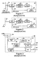
- FIG. 3 is a schematic representation of another embodiment of US Patent Application No. 10/620,769 .
- a synchronization channel 26 operates by detecting and extracting information from a USB 12 as USB signal traffic passes through to digital I/O bus interface circuitry 20 (not shown in this figure), and by generating both a local clock signal 28 and a local trigger signal 30.
- This embodiment employs circuitry to observe traffic through the USB and decode all SOF packets, which results in a pulse once every 1 ms.
- the local clock signal 28, from a controlled oscillator clock 32, is locked to the reception of the USB 1 kHz SOF packet in both phase and frequency.
- phase detector 40 is coupled to the controlled oscillator clock 32 via a filter 42.
- the local clock signal 28 is subsequently supplied to the transducer circuitry on the USB device (i.e. digital transducer 16 in figures 1 and 2 ), thus ensuring that all devices attached to the root hub are locked in frequency to the point at which they receive the SOF packet token.
- US Patent Application No. 10/620,769 also teaches a method and apparatus to further synchronize multiple local clocks in phase by measurement of signal propagation time from the host to each device and provision of clock phase compensation on each of the USB devices.
- a standard crystal oscillator has a central frequency tolerance of approximately 20 ppm with temperature stability of approximately ⁇ 50 ppm across the usable temperature range. Even this tolerance is unacceptable for highly accurate clock systems. Time critical systems often require temperature stabilised crystal oscillators with centre frequency tolerance and temperature stability of approximately 5 ppm or better.
- US Patent Application No. 10/620,769 also teaches a method of controlling the synchronized USB clock frequency by manufacture of a special USB host controller with local clock of precisely controlled reference frequency. Such a system would then produce a USB data stream with 1 kHz SOF clock accuracy of a few parts per million. This device is likely to be too costly to see widespread implementation in the highly competitive personal computer market; further, systems such as laptop computers and PDAs (personal digital assistants) have no provision to add on an aftermarket USB host controller.
- PDAs personal digital assistants
- US Patent No. 6,226,701 discloses a system for time-stamping real-time events within a USB, employing multiple counters and comparing elapsed time since USB SOF packets.
- This system requires a counter in both the USB device and the USB Host Controller to be activated by SOF tokens.
- the counter in the device is activated by the external event and stopped by the next SOF.
- the counter in the Host controller is reset and started by each SOF.
- the USB host controller interrogates the peripheral device which transfers data to the host controller indicating (i) that an event has occurred, and (ii) the time before start of frame value of the first timer.
- the USB host controller interrupts the host processor and transfers to it the data related to the peripheral device. In this way the system of this document can determine the elapsed time since the external event occurred and the processor read the second timer.
- Chambers et al. can perform basic event time-stamping, it requires a specific hardware implementation of the USB Host Controller and is therefore not compatible with a generic implementation of USB. Furthermore, that system relies on PC interrupt features and the associated timing restrictions of the real-time clock of the Host PC.
- USB devices any number of USB devices, up to some allowed maximum, can operate in a synchronized and triggered manner with local clocks both phase and frequency locked to precisely controlled arbitrary frequencies.
- the invention provides a method and apparatus according to independent claims 1 and 2.
- the periodic structure acts as a carrier for clock information, without itself constituting the clock frequency information.
- the clock may either be of the same frequency as the carrier or a different frequency according to any number of additional signals used to modify the carrier signal frequency.
- the circuitry for receiving the periodic data structure and generating the local clock signal can generate the local clock signal with a frequency that is a non-integral multiple of a frequency of the periodic data structure.
- the local clock signal can be generated with a frequency that is a non-integral multiple (including sub-multiple) of that of the periodic structure/carrier signal; this is also the case in other aspects of the invention described below. That is, the local clock signal need not be generated with a frequency that is a fixed multiple of the frequency of the periodic structure/carrier signal, but rather with a frequency that is calculated based on the actual frequency of the periodic structure/carrier signal. For example, if the frequency of the periodic structure/carrier signa is 1.01 kHz, according to the present invention it is possible to synchronize to substantially exactly 10 MHz (rather than to an integral multiple, such as 10.1 MHz).
- the circuitry for receiving the periodic data structure and generating a local clock signal may also be adapted to receive an information signal (such as from a microcontroller) and to generate the local clock signal from at least the periodic data structure and the information signal.
- an information signal such as from a microcontroller
- the circuitry for receiving the periodic data structure and generating a local clock signal may include a phase comparator, a controlled oscillator clock generator and frequency synthesis circuitry for generating a clock signal of arbitrary frequency.
- the periodic data structure comprises a USB Start of Frame (SOF) packet token.
- SOF USB Start of Frame
- the frequency of the periodic data structure can be determined, which may itself be used to determine, for example, the clock rate of a USB host controller.
- the USB may receive the USB data stream wirelessly, or the apparatus may include a USB bus connector for connection to the USB and for transmitting the USB data stream to the USB.
- the apparatus will commonly be in the form of a USB device, but need not be.
- the apparatus may be adapted to measure the frequency of the periodic data structure in only one of a plurality of devices and be configured to transmit a signal to other devices to control their local clocks accordingly.
- the reference signal or frequency source may comprise either a local reference clock or an external reference signal source (such as a connector for connection to an external reference clock). If an external reference clock is employed in this regard, it may be of arbitrarily high accuracy, and could be in the form of, for example, a precision frequency reference (such as a Caesium or Rubidium clock), a Global Positioning System (GPS) time server or an IEEE-1588 time server.
- a precision frequency reference such as a Caesium or Rubidium clock
- GPS Global Positioning System
- the apparatus may include a time-stamp latch and a reference time-stamp signal source, wherein the time-stamp latch is adapted to time stamp a data signal from the reference time-stamp signal source, whereby the time-stamp information can be synchronized to the reception of the carrier signal.
- the reference time-stamp signal source may comprise a connector for connection to an external reference time-stamp signal source.
- the method may include measuring the frequency of the periodic data structure in only one of a plurality of devices and transmitting a signal to other devices to control local clocks of the other devices accordingly.
- the method may include synchronizing events on a plurality of synchronized USBs.
- the method includes communicating information to a further plurality of USB devices on said USB devices such that said further USB devices are triggered to execute commands or functions in real-time and as required, such as by an operator.
- USB can currently support 127 devices (including hubs) and with few exceptions is limited to a range of 30 m.
- a GPS or IEEE-1588 signal (for example) can be used as the local timing reference for a plurality of USBs, so an essentially unlimited number of devices may be included in the system with no restriction on their locations.
- a globally synchronized system may be provided.
- the invention provides a method of synchronizing a plurality of synchronous multichannel USBs, comprising:
- the external frequency reference comprises Caesium or Rubidium clock sources, a clock source synchronized to a global positioning system (GPS) satellite-based navigation and timing system, a clock source synchronized to IEEE-1588 precision time protocol across Ethernet, or a clock source synchronized to a predefined time standard or protocol.
- GPS global positioning system
- the plurality of synchronous USBs comprise more than a maximum allowable number of USB devices attachable to a given USB.
- the plurality of synchronous USBs are able to transfer more data that a maximum allowable data throughput of a single USB.
- the invention provides a real-time synchronous multichannel USB, comprising:
- the USB is adapted to provide real time synchronization based on a signal received from a USB device attached to the USB.
- the USB is adapted to provide real time synchronization based on signals from a composite USB hub and a USB device attached to the USB.
- the USB is adapted to provide real time synchronization based on a signal from an external device adapted to observe USB traffic and provide information to a USB host system controller of the USB.
- the invention also provides a real-time, frequency and phase controlled, synchronous multichannel USB, comprising:
- the absolute time registers are synchronized to a real-time clock of a host computing or other system.
- the absolute time registers are synchronized to a real-time clock on one or more of the plurality of USB devices.
- the absolute time registers are synchronized to an external time reference.
- the external time reference is adapted to synchronize to a global positioning system (GPS) satellite-based navigation and timing system, complies with IEEE-1588 precision time protocol across Ethernet, or is provided by a time standard or protocol.
- GPS global positioning system
- the invention provides a System synchronizable to a synchronized Ethernet according to independent claim 13.
- the synchronization channel comprises one or more USB devices attached to the synchronized USB, a compound USB Hub and USB device function, or a device that observes USB data traffic on the synchronized USB but is not an attached member of the synchronized USB.
- the USB may further comprise a USB hub function for USB device tree expansion, a USB device function, a USB synchronization function for synchronizing the synchronized USB, a local reference clock, and an IEEE-1588 interface.
- the local clock is the IEEE-1588 master clock or an IEEE-1588 slave clock.
- the data channel comprises a USB device function or a compound USB Hub and USB device function.
- the USB host system is a personal computer, a USB-on-the-go controller, or an embedded controller combined with a compound USB Hub and USB device function.
- apparatuses according to the invention can be embodied in various ways.
- such devices could be constructed in the form of multiple components on a printed circuit or printed wiring board, on a ceramic substrate or at the semiconductor level, that is, as a single silicon (or other semiconductor material) chip.
- USB device 50 includes a bus connector 54, digital I/O bus interface circuitry 56, a microcontroller 58, a digitally controlled transducer 60 and synchronization circuitry in the form of synchronizer 62 (described in greater detail below).
- the digital I/O bus interface circuitry 56 acts as a transceiver for USB data detected at bus connector 54, passing the USB data to microcontroller 58.
- the microcontroller 58 provides information 64 to synchronizer 62 for accurate frequency synthesis and a direct control channel 66 to digitally controlled transducer 60.
- the carrier signal referred to above is a periodic data structure and hence usable as a carrier signal; in this and the other embodiments described below it is in the form of the SOF packet token, which provides a periodic low resolution signal of ambiguous frequency that is broadcast to all but Low-Speed devices connected to a given Host Controller.
- the carrier signal once decoded from the USB traffic, is combined with a scaling factor to generate synchronization information and hence to synthesize a local clock signal with precise control of the clock frequency.
- FIG 5 is a detailed schematic diagram of the synchronizer 62 of this embodiment.
- Synchronizer 62 includes a matched filter 68 to observe USB traffic through bus connector 54, decode the aforementioned periodic carrier signals (in the form, in this embodiment, of SOF packet tokens) and send a clock synchronization signal 70 to local clock synthesis circuitry 72.
- a frequency-accurate local clock signal 74 is synthesized from the decoded carrier signal (i.e. clock synchronization signal 70), using information signal 76 provided by microcontroller 58.
- local clock signal 74 has a frequency several orders of magnitude higher than has clock synchronization signal 70 and is divided down by a frequency divider 78 to a divided signal 80 of frequency closer to that of clock synchronization signal 70.
- Local clock synthesis circuitry 72 manipulates its input signals (i.e. clock synchronization signal 70 and divided signal 80) according to information signal 76 provided by microcontroller 58.
- the resulting two output signals 82 and 84 are passed to a phase comparator 86.
- the phase comparator 86 is coupled via a filter 88 to a controlled oscillator clock generator 90.
- Accurate local clock signal 74 is then used as clock signal for trigger circuitry to generate a phase accurate trigger signal 92.
- Synchronizer 62 includes a further matched filter 94 that also decodes USB data received through the USB bus connector 54 and produces a trigger enable signal 96 upon detection of the required trigger signal from the USB data stream.
- the trigger enable signal 96 is passed to a data latch 98, which uses the local frequency accurate clock signal 74 to clock the trigger enable signal 96 through to form phase accurate trigger signal 92.
- a USB device 100 employs a method for determining the effective clock rate of the USB Host Controller by accurately measuring the frequency of the SOF packet. This signal can then be considered a carrier for information about the Host Controller clock rate and the carrier signal is broadcast to all connected USB devices. The carrier signal embedded in the normal USB protocol is thus decoded and its frequency measured to determine the effective clock rate of the USB Host Controller clock.
- FIG 6 is a schematic diagram of a device 100 for synchronizing a USB according to a second embodiment of the invention, which includes a USB bus connector 102 for connection to a USB.
- Device 100 has a first connector 104 for receiving an external reference clock signal, and a second connector 106 for receiving an external reference time-stamp signal, by mean of which device 100 measures the frequency of the SOF packet signal (or carrier signal).
- Device 100 includes USB monitoring circuitry 108 to observe the USB data stream, a microcontroller 110, timing measurement circuitry 112 and information bus 114 (incorporating an analog and/or a digital bus) for communication between microcontroller 110 and timing measurement circuitry 112.
- device 100 determines the SOF packet carrier signal frequency and by implication the USB Host Controller frequency, and can pass information about the frequency back to a microcontroller and indeed back to a host PC, it will be apparent to those skilled in the art that this approach may also be used with non-USB devices. For example, this approach may be used in a device that merely detects and decodes a USB data stream but is not a USB device.
- both the connector for receiving external reference clock signal 104 and the connector for receiving external reference time-stamp signal 106 can be bidirectional ports. Such bidirectional ports can transmit or receive clock and data signals (including time-stamp information) to or from an external device. It will also be apparent to those skilled in the art that such signals can be used for controlling external devices.
- Timing measurement circuitry 112 includes a matched filter 116 for decoding the carrier synchronization signal in the USB data stream to output a decoded carrier signal 118, and frequency measurement circuitry 120 that compares decoded carrier signal 118 with a local reference signal 122.
- the frequency measurement circuitry 120 produces clock accuracy information signal 124 indicative of the absolute clock accuracy of the carrier signal and hence indicative of the clock rate of the USB Host Controller.
- Local reference signal 122 is provided by multiplexer 126, which selects either local reference clock signal 128, generated by local reference clock 130, or an external reference signal 132 (provided by first connector 104), as controlled by microcontroller 110 through information bus 114.
- the decoded carrier signal 118 is also used by time-stamp latch 134, which time stamps a data signal 136 received from external time-stamp second connector 106, and output at 138 to information bus 114. In this way, absolute time-stamp information from an external source can be synchronized to the reception of the carrier signal.
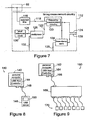
- FIG 8 is a schematic diagram of a USB system 140 according to a third embodiment of the present invention, in which a personal computer 142 with a USB Host Controller 144 is attached to a single USB device 146 at a USB 148.
- the USB device 144 contains timing measurement circuitry 150 (as per timing measurement circuitry 112 of figure 7 ) to measure repetitive carrier signal frequency using an internal reference clock (comparable to local reference clock 130 of figure 7 ) to an arbitrary degree.
- the absolute frequency of the clock carrier signal of the USB Host Controller 144 is determined by means of circuitry (i.e. the timing measurement circuitry 150) contained solely within a USB device.
- PDA personal digital assistant
- mobile communication device that contains a USB host controller or USB on-the-go controller.
- FIG. 9 is a schematic diagram of a USB system 160 according to a fourth embodiment of the present invention, in which personal computer 162 with a USB Host Controller 164 is attached to a USB hub 166 at a USB 168.
- USB Hub 168 provides connectivity to a plurality of USB devices 170, each of which contains timing measurement circuitry (comparable to timing measurement circuitry 150 of USB system 140) to measure repetitive carrier signal frequency using an internal reference clock (comparable to local reference clock 130 of figure 7 ).
- Each of the USB devices 170 measures carrier signal frequency with some finite error. As the error is essentially random, statistical analysis is used to analyse measurements from the USB devices 170 and thereby reduce the overall uncertainty in measurement of the carrier signal frequency.
- the absolute frequency of the clock carrier signal frequency of USB Host Controller 164 is determined to a greater accuracy than would be achievable with a single USB device.
- FIG 10 is a schematic representation of a USB Timing Hub 180 according to a fifth embodiment of the present invention.
- the USB Timing Hub 180 has an upstream port 182 for connection to a Host Controller (or intermediate upstream device between USB Timing Hub 180 and a Host Controller), a plurality of downstream ports 184 (that provide USB expansion), an external reference clock input port 186, and an external reference time-stamp input port 188.
- Host Controller or intermediate upstream device between USB Timing Hub 180 and a Host Controller
- a plurality of downstream ports 184 that provide USB expansion
- an external reference clock input port 186 an external reference time-stamp input port 188.
- USB upstream port 182 is connected to USB Hub circuitry 190 that provides USB expansion to the plurality of downstream USB ports 184; one of the downstream USB ports 184 is directed to an internal USB device 192.
- Internal USB device 192 is connected to timing measurement circuitry 194 (comparable to timing measurement circuitry 112 of figure 6 ) via a communication bus 196.
- the timing measurement circuitry 194 contains an internal local reference clock (comparable to local reference clock 130 of figure 7 ) and also receives information from both external reference clock input port 186 and external time-stamp input port 188.
- the timing measurement circuitry 194 also observes USB data traffic on the upstream port 182 with USB monitoring circuitry 198 and uses this signal 199 to decode the USB Host Controller clock carrier signal for measurement of the carrier signal frequency.
- USB Timing Hub 180 contains both circuitry 194 (of the type described by reference to figure 7 ) to determine the absolute clock rate of a USB Host Controller and normal USB Hub circuitry 190.
- Such a hybrid device provides both USB Host Controller clock carrier signal frequency information and expansion of the USB.
- the synchronous channel count of a USB system can be extended beyond that allowed by the USB specification (which is currently 127 devices including hubs).
- This embodiment allows a plurality of discrete USBs to be synchronized by delivering a common external reference clock signal to each of the USBs.
- the common reference clock signal is then used to measure the USB Host Controller clock carrier signal of each of the USBs and subsequently to use that information to synthesise a known frequency on the local clocks on each USB device connected to any of the USBs to an essentially arbitrary degree.
- FIG 11 is a schematic view of a system 200 according to a sixth embodiment for increasing the synchronous channel count of a USB, in which a plurality of synchronized USBs are synchronized to an arbitrary degree.
- the system 200 includes a plurality of personal computers 202, each containing a USB Host Controller 204.
- Each personal computer 202 is connected to a hybrid USB Timing Hub 206 (of the type described and illustrated at 180 to figure 10 ); each USB Timing Hub 206 provides a plurality of synchronized USBs 208 to allow expansion to a plurality of USB devices 210.
- An external reference clock 212 provides a signal to the synchronized USBs 208 by means of the USB Timing Hubs 206.
- system 200 omits the USB Timing Hubs 206, and the USB devices are configured to receive the external reference clock signal directly.
- the use of the USB Timing Hubs 206 are preferred.
- a synchronized USB is provided with an external reference clock signal that is frequency accurate and time-stamp accurate to an arbitrary degree. These signals allow the USB to be synchronized to an arbitrary accuracy.
- This embodiment uses an external Global Positioning System (GPS) Time Server as the external synchronization reference.
- GPS Global Positioning System
- the GPS Time Server reference clock signal is delivered by means of satellite communication.
- the GPS Time Server can deliver absolute time-stamp information accurate to an arbitrary degree, regardless of position, essentially anywhere.
- FIG 12 is a schematic diagram of a system 220 in which a USB 222 is synchronized to a GPS Time Server 224.
- System 220 includes a personal computer 226 containing a USB Host Controller 228, connected to synchronous USB 222, where synchronous clock frequency is accurate to an arbitrary degree.
- USB port 230 of personal computer 226 connects to USB Timing Hub 232, which provides downstream expansion ports 234 for the attachment of additional USB devices 236.
- USB Timing Hub 232 (of the type described and illustrated at 180 to figure 10 ) also has ports 238, 240 for receiving, respectively, a reference clock signal 242 and time-stamp information 244 from GPS Time Server 224.
- the GPS Timer Server 224 is connected to an antenna 246 for receiving GPS time and position information.
- FIG 13 is accordingly a schematic representation of a USB 250 globally synchronized according to this embodiment.
- Globally synchronized USB 250 comprises a plurality of USBs located at different locations 252; each is of the type shown at 222 in figure 12 , so each is synchronized by a separate GPS Time Server.
- the plurality of GPS Time Servers provide reference clock signals that are frequency locked to an essentially arbitrary degree by means of satellite communication.
- the plurality of GPS Time Servers each deliver absolute time-stamp information to their respective USB Timing Hub accurate to an arbitrary degree, regardless of position, anywhere on earth.
- a plurality of otherwise independent USBs are synchronized.
- Such a system is capable of accurate synchronization anywhere on earth for a widely distributed synchronous USB.
- This also has the capability of unlimited channel count by adding as many synchronized USBs (222 of figure 12 ) as desired.
- a synchronized USB can be synchronized to a synchronized Ethernet (that is, a network that is in internal data communication according to the Ethernet protocol).
- the synchronized USB is provided with an external signal from a synchronized Ethernet that contains timing information according to IEEE-1588 Precision Time Protocol.
- Said external signal contains both an Ethernet communication pathway and a Precision Time Protocol pathway. In this way, both data and timing information can be communicated between USB and Ethernet systems.
- FIG 14 is a schematic diagram 260 of a USB 262 synchronized to Ethernet 264.
- the synchronized Ethernet 264 contains a plurality of devices 266 to be synchronized and an Ethernet Boundary Clock 268.
- the Boundary Clock 268 performs Ethernet connectivity between devices as well as compensating for latency and timing jitter present in traditional Ethernet switches and routers.
- the synchronized USB 262 includes a personal computer 270 with a USB Host Controller 272 and, connected to Host Controller 272, a hybrid USB Timing Hub 274.
- USB Timing Hub 274 provides connectivity expansion to a plurality of USB devices 276.
- USB Timing Hub 274 includes an IEEE-1588 compatible port 278 for communication of data and timing information 280 to synchronous Ethernet 264.
- the IEEE-1588 Precision Time Protocol contains a protocol for determining which node of a network is the time-base master. It will be apparent to those skilled in the art that any node (viz. device 266) of the synchronous Ethernet 264 or the synchronous USB 262 can be the time-base master clock depending on the absolute accuracy of all device clocks.
- FIG 15 is a detailed schematic diagram of USB Timing Hub 274 of USB 262 of figure 14 .
- the hybrid USB Timing Hub 274 has an upstream port 292 for connection to Host Controller 272 (or an intermediate upstream device between USB Timing Hub 274 and Host Controller 272), a plurality of downstream ports 294 (that provide USB expansion) and external port 278 for connectivity to the synchronous Ethernet.
- USB Timing Hub 274 includes USB Hub circuitry 298, to which USB upstream port 292 is connected, that provides USB expansion to the plurality of downstream USB ports 294; one of the downstream USB ports 294 is directed to an internal USB device 300.
- Internal USB device 300 is connected to timing measurement circuitry 302 (comparable to timing measurement circuitry 112 of figure 6 ) via a communication bus 304.
- Timing measurement circuitry 302 also observes USB data traffic on the upstream port 292 by means of USB monitoring circuitry 306, and uses the signal 308 therefrom to decode the USB Host Controller clock carrier signal for measurement of the carrier signal frequency.
- Timing measurement circuitry 302 contains an internal local reference clock (comparable to local reference clock 130 of figure 7 ) and also receives or transmits information to an additional local clock 310 through clock control channel 312. In this way, either the local clock 310 or a clock in the form of timing measurement circuitry 302 can be the local master clock for use determining the carrier signal frequency.
- USB Timing Hub 274 includes a synchronous Ethernet controller 314 to which is connected external port 278 and which provides external Ethernet connectivity and supports IEEE-1588 Precision Time Protocol.
- Synchronous Ethernet controller 314 has a data channel 316 for communication of data between the external Ethernet (shown at 264 in figure 14 ) and internal USB device 300. In this way data is transferred from the external synchronous Ethernet 264 via synchronous Ethernet controller 314 and internal USB device 300 the personal computer (270 of figure 14 ).
- Synchronous Ethernet controller 314 also contains a synchronization channel 318 through which local clock 310 can be synchronized to external Ethernet 264. In this way timing information is passed between synchronous Ethernet controller 314 and local clock 310, thereby effecting a hybrid synchronized USB/Ethernet system using the best of both interfaces: Ethernet provides wide ranging connectivity but limited synchronization capabilities, while USB provides a local precision synchronization network.
- a USB is provided that provides a control path that is not subject to the normal latency delays of USB (such as the 30 ms time frame implied by the typically 30 ms thread cycle time of the Windows (trade mark) operating system).
- FIG 16 is a schematic diagram of a hybrid USB hub 330 according to this embodiment that provides an additional data pathway for reducing USB control loop latency.
- USB hub 330 has an upstream pot 332 for connection to a Host Controller (or intermediate upstream device between Hybrid USB Hub 330 and a Host Controller), a plurality of downstream ports 334 (that provide USB expansion) and an external control port 336 for connectivity to external interfaces, equipment or transducers.
- USB hub 330 also has USB Hub circuitry 338 (connected to Upstream port 332) that provides USB expansion to the plurality of downstream USB ports 334, and an internal USB device 340 to which is directed one of the downstream USB ports 334.
- USB hub 330 includes an internal USB device 340 and a Data Decoder and Processor 342, mutually connected by a communication bus 344.
- Interface 350 can be an Ethernet interface, a serial communication interface (such as a SPI (Serial Peripheral Interface) bus, a CAN Controller Area Network, a ProfiBus, aProcess Field Bus or a USB (including USB-on-the-go), a parallel communication interface (such as a Centronics (trade mark) Parallel Port or an IDE (Integrated Drive Electronics) bus).
- SPI Serial Peripheral Interface
- CAN Controller Area Network such as a serial Peripheral Interface
- ProfiBus Serial Peripheral Interface
- aProcess Field Bus or a USB (including USB-on-the-go)
- parallel communication interface such as a Centronics (trade mark) Parallel Port or an IDE (Integrated Drive Electronics) bus
- external control port 336 can provide either single-ended or differential signalling, and can be adapted to any desired form of connectivity, whether copper cabling, fibre-optical cabling, wireless communication channels or otherwise.
- USB hub 330 data that is being transmitted between a Host Controller and any USB device attached to downstream ports 334 can be intercepted and interpreted in USB hub 330 and used to immediately control an external device through the external control port 336. This circumvents the normal communication and control loop latency of USB.
- USB Hub Although various embodiments of the present invention described herein include a hybrid USB Hub, these techniques need not be employed in a USB hub, but may in fact be used in any device that is at least attached to a USB for the purpose of detecting USB data flows and acting on the information contained therein.
- FIG. 17 is a schematic diagram of USB monitoring circuitry 360 (comparable to USB monitoring circuitry 346 of USB hub 330 figure 16 ); USB monitoring circuitry 360 has an upstream port 362 for connection to the Host Controller side of the bus, a downstream port 364 for connection to the device side of the bus, a USB data monitoring port 366 for transmission of a replica of the USB data stream present at the USB upstream port 362, a data switch control port 368 for controlling internal data pathways inside the circuit, a bidirectional data port 370 and buffering circuitry 372.
- Buffering circuitry 372 observes USB data signal 374 (which comprises bidirectional communications between the Host Controller and attached devices) and provides a buffered replica signal 376 thereof.
- Replica signal 376 is an exact copy of the bidirectional communication present on the USB, is transmitted on the USB data monitoring port 366 and is typically comparable to signal 308 of figure 15 .
- USB monitoring circuitry 360 is able to monitor all USB data packets and provide a buffered replica signal 376 of USB data signal 374 for use by external circuitry.
- Buffered replica signal 376 can be used by external circuitry for decoding periodic signal structures from the Host Controller within USB data to identify carrier signals which contain information about the clock rate of the USB Host Controller.
- Buffered replica signal 376 can also be used to decode information from all downstream USB devices as it passes upstream toward the Host Controller. In this way, direct action can be taken on the information from downstream devices without first requiring the Host Controller and associated operating system to process and act on the data.
- USB monitoring circuitry 360 also includes additional circuitry for advanced data management, switching and reducing USB control loop latency, including a USB data switch 378 (shown as a pair of simple single pole switches in figure 17 for simplicity, though in reality USB data signals are differential) and data controller circuitry 380 for controlling USB data switch 378.
- USB data switch 378 contains an upstream switch 382 and a downstream switch 384, and is configured to synchronously direct USB data signal 374 from upstream port 362 either directly to the downstream port 364 (the configuration shown in figure 17 ) or utilising a bidirectional data stream 386 from external circuitry via bidirectional data port 370.
- USB data switch 378 has access to buffered replica signal 376, and data controller circuitry 380 is configured by data switch control port 368. In this way, USB data switch 378 can be switched synchronously with the USB data signal as monitored at 374.
- USB monitoring circuitry 360 is also able to dynamically configure itself to insert data within a USB data stream.
- a message from the Host Controller to a device may be intercepted and altered by USB monitoring circuitry.
- software can be configured to provide regular polling of a particular USB device with a known data packet size.
- USB monitoring circuitry having access to the size of a specified regularly polled packet, can insert data within the payload of a transaction by synchronously bypassing the direct connection (viz. the configuration of USB data switch 378 shown in figure 17 ) and inserting data into the payload field of the transaction.
- Figure 18A depicts the configuration of USB data switch 378 of figure 17 for downstream insertion of payload data 388 at 378'; figure 18B depicts the configuration of USB data switch 378 of figure 17 for upstream insertion of payload data 390 at 378".
- the switch must initially be configured as shown at 378 in figure 17 while the host transmits the transaction packet header information, but switch to configuration 378' of figure 18A for insertion of the payload and CRC data 388.
- the device waits until it detects the polling request from the Host Controller before switching to configuration 378" of figure 18B for transmission of the entire upstream transaction (including header). It should be noted that the device may alternatively wait for the upstream transaction packet header pass upstream before switching to configuration 378" of figure 18B and inserting the payload data 390.
- Figure 18C is a schematic timing diagram for downstream data insertion (upper portion of the figure) and the upstream data insertion (lower portion of the figure), indicating the configuration of the USB data switch.
- a Hybrid USB Host Controller that is synchronized to a synchronized Ethernet, to ensure that the attached synchronized USB is also synchronized to the synchronized Ethernet.
- the Hybrid USB Host Controller is provided with an external signal from a synchronized Ethernet that contains timing information according to IEEE-1588 Precision Time Protocol.
- the external signal contains both an Ethernet communication pathway and a Precision Time Protocol pathway. In this way, both data and timing information can be communicated between Hybrid USB Host Controller and Ethernet systems.
- the Hybrid USB Host Controller contains an embedded microcontroller so that it is a stand-alone device that is not dependent on a host personal computer.
- the Hybrid USB Host Controller may contain a standard USB Host controller, a USB-on-the-go Host Controller, a wireless USB Host Controller or any other form of USB Host Controller.
- FIG 19 is a schematic diagram of a system 400 according to this embodiment, comprising stand-alone USB 402 (that is, one containing an embedded controller that does not require attachment to a personal computer) and an Ethernet 404, synchronized to each other.
- the Ethernet 404 typically contains an Ethernet Boundary Clock 406 and a plurality of devices to be synchronized 408.
- Boundary Clock 406 performs Ethernet connectivity between devices as well as compensating for latency and timing jitter present in traditional Ethernet switches and routers.
- USB 402 consists of a Hybrid USB Host Controller 410 and a plurality of USB devices (or USB Hubs for further expansion) 412.
- Hybrid USB Controller 410 contains an embedded USB Hub functionality providing a plurality of downstream expansion ports.
- Hybrid USB Controller 410 also includes an IEEE-1588 compatible port 414 for communication of data and timing information 416 to Ethernet 404.
- FIG 20 is a more detailed schematic diagram of Hybrid USB Host Controller 410 of figure 19 .
- Hybrid USB Host Controller 470 has a plurality of downstream ports 472 (that provide USB expansion), an embedded controller 474, USB Hub circuitry 478 and USB master clock circuitry 480.
- Controller 474 has an embedded microcontroller 482, external interface circuitry 484 and a USB Host Controller 486.
- USB Host Controller 486 is connected to USB Hub circuitry 478 that provides USB expansion to the plurality of downstream USB ports 472 and USB master clock circuitry 480 through a clock bus 488.
- USB master clock circuitry 480 contains an internal local reference clock 490 and also receives or transmits information to an additional local clock 492 (also a part of Hybrid USB Host Controller 410, and in the form of a synchronous Ethernet IEEE-1588 clock) through a clock control channel 494.
- Hybrid USB Host Controller 410 further includes a synchronous Ethernet controller 496, to which external port 414 is connected and which provides external Ethernet connectivity and supports IEEE-1588 Precision Time Protocol.
- Synchronous Ethernet controller 496 has a data channel 498 for communication of data between the external Ethernet and external interface circuitry 484 of embedded controller 474. A bidirectional data link is therefore provided between the external synchronous Ethernet and the synchronized USB through synchronous Ethernet controller 496 and the embedded controller 474.
- Synchronous Ethernet controller 496 also has a clock control channel 500 for communicating with synchronous Ethernet clock 492.
- IEEE-1588 clock 492 may be either the bus master if it is more accurate than the clocks of other attached IEEE-1588 clocks or a slave clock that is slaved to a more accurate attached IEEE-1588 clock.
- Hybrid USB Host Controller 410 includes a control channel 502 between external interface circuitry 484 of embedded controller 474 and USB master clock circuitry 480 enabling the embedded controller 474 to control clock signals. In a similar way either the local reference clock 490 or the IEEE-1588 clock 492 acts as the system master clock, according to which is the more accurate.
- USB Host Controller 486 uses the clock signal from clock bus 488 as its master timing reference.
- This clock signal can be precisely tuned in USB master clock circuitry 480 to provide a frequency accurate time reference to arbitrary precision for synchronous USB control. Accordingly, the frequency of a periodic signal structure (such as a Start of Frame token) in the USB data stream can be accurately controlled, resulting in a synchronized USB with precisely controlled timing. In this way a hybrid synchronized USB/Ethernet system is achieved without requiring a personal computer. It will be apparent, in addition, that latency can be improved in this arrangement according to the approach described in the context of the embodiments of figures 16 and 17 .
- a USB device is shown schematically with a USB at 510 in figure 21 .
- the synchronized USB device might be said to have some notion of (or data indicative of) real time.
- This notion or data of time is derived from USB bus transactions, the USB data stream and information received from the host system.
- Such a notion of real time is shared by all devices attached to the same USB.
- USB device 520 includes a bus connector 522 for connecting to USB 524, digital I/O bus interface circuitry 526, a microcontroller 528, a digitally controlled transducer 530, synchronization circuitry in the form of synchronizer 532 (comparable to synchronizer circuitry 62 of figure 5 ) and real time clock 534.
- the digital I/O bus interface circuitry 526 acts as a transceiver for USB data detected at bus connector 524, and passes the USB data to microcontroller 528.
- the microcontroller 528 is provided with an information channel 536 to synchronizer 532 and a direct control channel 538 to digitally controlled transducer 530.
- USB device 520 has circuitry 540 at USB connector 522 that detects USB data traffic on USB 524 , and generates and passes a replica 542 of the USB data traffic to synchronizer 532.
- Synchronizer 532 (which is comparable to synchronizer 46 of figure 4 ) generates a local clock signal 544 that is frequency and phase controlled to an arbitrary precision, and will be synchronous with those of any similar USB devices attached to the same USB 524.
- Local clock signal 544 is passed to both the digitally controlled transducer 530 to control its operation and to real time clock 534.
- Real time clock 534 can be synchronized to an absolute time and then clocked by local clock signal 544. In this way, a plurality of USB devices can operate sharing a common notion of real time each being clocked by a synchronous local clock. Synchronization of the real time clock 534 is initiated by a command from the host personal computer; this command is interpreted by microcontroller 528 and transferred to both synchronizer 532 (via information channel 536) and real time clock 534 through another information channel 546. Synchronizer 532 then acts to synchronize real time clock 534 through a real time synchronizing channel 548. In this way, the real time clock can be synchronized to a known time. Real time clock 534 can then deliver real time trigger signals 550 (which may also include a time stamp from the real time clock) to control the operation of digitally controlled transducer 530 such that it performs actions at specified time.
- real time trigger signals 550 which may also include a time stamp from the real time clock
- FIG 22 is a detailed schematic diagram of the real time clock 534 of USB device 520 of this embodiment.
- Real time clock 534 has a control port 558 for communication with microcontroller 528 (see figure 21 ), a synchronous clock input port 560 for receiving synchronous clock signals 544 from synchronizer 532 (see figure 21 ), a synchronizing port 562 for receiving synchronizing signals on synchronizing channel 546 (see figure 21 ), an output port 564 and an input event/timestamp port 566.
- Control port 558 receives information signals which are decoded by interface 568 to provide a data signal 570 that contains the absolute time value, which is loaded into a temporary register 572 (for subsequent synchronous latching into real time clock counter 574), a data latch signal 576 for latching data signal 570 into the real time clock counter 574, a counter enable signal 578 for enabling the real time clock counter 574, and another data signal 580 to be loaded into a counter comparator 582.
- Real time clock counter 574 also receives a synchronous clock signal 584 from synchronous clock input port 560, which is used to increment the real time clock counter 574, and a resynchronize signal 586 from synchronizing port 562, which can be used to synchronously clear the real time clock counter 574.
- the resynchronize signal 586 is generated from synchronizer 532 such that it occurs synchronously with a start of frame (SOF) token in the USB (or more precisely, synchronously with a synthetic SOF).
- SOF start of frame
- This synchronizing synthetic SOF token frame number is known to the host controller (which keeps track of rollover of this number since the host began) and can therefore synchronize the device (or a plurality of similar devices) at the same point in time.
- the host maintains knowledge of the rollover of this synthetic SOF token number and of the absolute timestamp of the real time clock counter 574, so USB devices need not be synchronized at the same point in time. Once a single USB device has been synchronized to real time according to this technique, the host can calculate the real time at any future synthetic SOF frame token. This allows any number of devices to be synchronized in a sequential manner.
- real time clock counter 574 can either be synchronously loaded with a known 'real time' by microcontroller 528 (see figure 21 ) and time counting initiated by resynchronizing signal 586, or synchronously cleared by resynchronizing signal 586 with the counter incremented in both cases by synchronous clock signal 584.
- the system controller (such as a personal computer) then determines how the notion of time is represented by the real time clock counter 574.
- the real time value 588 (a data signal) is clocked out of real time counter 574 on each cycle of synchronous clock signal 584 to interface 590 which provides signals for external circuitry through output port 564.
- real time clock 534 can be configured to provide a trigger signal 592 by comparing the instantaneous real time value 588 with a data signal that has previously been latched into counter comparator 582. Trigger signal 592 is then passed to output interface 590 for transmission to external circuitry.
- Interface 590 also receives external signals from an event with associated timestamp data from external event/timestamp port 566. This data 592 is passed to real time clock counter circuitry 574 for calibration and setting of real time of the local clock contained therein.
- synchronous clock signal 584 and resynchronizing signal 586 are synchronous with carrier signals (as described above in the context of USB device 50 of figure 4 ). Thus, it is possible to determine the real time of the reception of these carrier signals and hence set the real time of real time clock counter 574 of figure 22 .
- Figure 23 is a timing diagram 600 of the USB device 520 of figure 21 .
- External event 602 of known real time can be used to start a local counter 604, which is clocked from the synchronous clock signal 606 (derived from synchronizer circuitry 62 of figure 4 ), and the real time 608 of external event 602 is latched into the device.
- Reception of the next decoded carrier signal 610 (synthetic start of frame) token stops local counter 604 and latches the number 612 of the frame token.
- the host controller can then determine the real time of latched frame token number 612 using the time elapsed of local counter 604 (time ⁇ t between the event and the start of frame token).
- an external event of known real time at event/timestamp port 566 can be used to determine the real time of the arrival of local carrier signal and hence set (or calibrate) the real time of a USB device 520.
- Real time determined by this method is latched into real time clock counter (574 of figure 22 ) at 614.
- Such an externally derived real time event and time stamp may be generated by a known frequency and time reference, such as a precision Caesium clock, a GPS time server that is locked to a global positioning satellite system or an IEEE-1588 precision time protocol device.
- the host personal computer can assign its own notion of time (from its internal, inaccurate real time clock) to the synchronous USB.
- This method merely assigns the personal computer's notion of time to a given carrier frame number as the reference time for use by the real time clock counter. From that time forward, the synchronous USB has highly precise relative accuracy (as defined by its real time clock counter circuitry) but with an offset from absolute time determined by the initial error of the host personal computer's real time clock.
- the carrier signal frequency can be determined to an arbitrary degree, using the approach employed in device 100 of figure 6 .
- This is a method of generating a time stamp of an external event, relative to a known carrier signal number.
- this approach can be implemented in a hub or a USB device, or in a device attached to the USB. It can also be implemented once or in multiple devices to improve accuracy by statistical means.
- a USB device according to a twelfth embodiment of the present invention is shown schematically at 630 in figure 24 .
- the synchronized USB device 630 can time stamp external events according to its own notion of time, which has either been calibrated by its own real time clock or by an externally provided real time clock and time stamp.
- the USB device 630 has an upstream port 632 for connection to a Host Controller (or intermediate upstream device between USB device 630 and such a host controller), an external trigger port 634 and a data port 636 for communication of time stamp information.
- USB device 630 also includes digital I/O bus interface circuitry 638, microcontroller 640 and synchronizing time stamp circuitry 642.
- Time stamp circuitry 642 includes synchronizing circuitry 646 (comparable to timing measurement circuitry 302 of figure 15 ) that observes USB data traffic on the upstream port 632 by means of USB monitoring circuitry 644 to synchronize a local clock using the carrier signal contained in decoded USB data stream signal 650 and real time clock circuitry 648 (comparable to real time clock 534 of figure 22 ).
- External event signals (otherwise known as external triggers) connected to external trigger port 634 and time stamp information present on data port 636 are passed to time stamp circuitry 642 for processing.
- external events triggers
- associated time stamps can be passed to the device and correlated with a synchronized local clock contained in synchronizing circuitry 646.
- Host Controller may be used to specify a standard USB Host controller, a USB-on-the-go Host Controller, a wireless USB Host Controller or any other form of USB Host Controller.
Claims (13)
- USB-Zeitsteuerungs-Hub (180) zum Synchronisieren einer Vielzaht von USB-Geräten, umfassend:Hub-Schaltungen (190), die einen Upstream-Port (182) zur Verbindung mit einem USB-Host-System und eine Vielzahl von Downstream-Ports (184) umfassen;Zeitsteuerungs-Messschaltungen (194), die durch eine interne USB-Vorrichtung (192) mit den Hub-Schaltungen (190) verbunden sind;einen Externer-Referenztakt-Eingangs-Port (186) zum Empfangen eines externen Referenztaktsignals, das eine bekannte Frequenz aufweist;wobei die Zeitsteuerungs-Messschaltungen (194) das externe Referenztaktsignal mit einer Frequenz von periodischen Datenstrukturen in einem aus dem USB-Host-System empfangenen USB-Datenstrom vergleichen, um die Frequenz der periodischen Datenstrukturen zu bestimmen, unddie interne USB-Vorrichtung (192) dazu ausgebildet ist, ein Signal, das die Frequenz der periodischen Datenstrukturen anzeigt, über den Host-Controller an die Vielzahl von USB-Geräten zu senden, wodurch ermöglicht wird, dass die Vielzahl von USB-Geräten ein lokales Taktsignal synthetisieren, das eine gegebene Frequenz aufweist.
- Verfahren zum Synchronisieren einer Vielzahl von USB-Geräten, umfassend:1) Zuführen eines externen Referenztaktsignals, das eine bekannte Frequenz aufweist, zu einem Zeitsteuerungs-Hub (180), der mit einem USB-Host-System in Upstream-Richtung und mit der Vielzahl von USB-Geräten In Downstream-Richtung verbunden ist;2) Zeitsteuerungs-Messschaltungen (194) in dem Zeitsteuerungs-Hub (180), die das externe Referenztaktsignal mit einer Frequenz von periodischen Datenstrukturen in einem aus dem USB-Host-System empfangenen USB-Datenstrom vergleichen, um die Frequenz der periodischen Datenstrukturen zu bestimmen; und3) Senden eines Signals an die Vielzahl von USB-Geräten, das die Frequenz der periodischen Datenstrukturen anzeigt, wodurch ermöglicht wird, dass die Vielzahl von USB-Geräten einen lokalen Takt synthetisieren, der eine gegebene Frequenz aufweist,
- Verfahren gemäß Anspruch 2, weiterhin umfassend, eine Vielzahl von USBs zu synchronisieren durch:Durchführen der Schritte 1 bis 3 für jeden von einer Vielzahl von Zeitsteuerungs-Hubs (180), die mit einer Vielzahl von jeweiligen USB-Host-Systemen in Upstream-Richtung und mit einer jeweiligen Vielzahl von USB-Geräten in Downstream-Richtung verbunden sind;wobei das externe Referenztaktsignal durch eine Vielzahl von synchronen Frequenzreferenzen und Zeitstempelausgaben aus einer Taktverteilungsvorrichtung zugeführt wird.
- Verfahren gemäß Anspruch 3, wobei die Taktverteilungsvorrichtung Cäsium-oder Rubidlum-Taktquellen, eine mit einem satellitenbasierten Globales-Posltlonierungssystem-(GPS-) Navigations-und Zeitsteuerungssystem verbundene Taktquelle, eine mit dem IEE-E-1588-Präzisionszeitprotokoll über Ethernet synchronisierte Taktquelle oder eine mit einem vorbestimmten Zeltstandard oder-protokoll synchronisierte Taktquelle umfasst.
- Verfahren gemäß Anspruch 3, wobei eine Gesamtzahl der jeweiligen Vielzahl von USB-Geräten größer als eine maximal zulässige Anzahl von mit einem gegebenen USB verbindbaren USB-Geräten ist.
- Verfahren gemäß Anspruch 3, wobei eine Gesamtzahl der Vielzahl von USB-Geräten in der Lage ist, mehr Daten als ein maximal zulässiger Datendurchsatz eines einzelnen USB zu übertragen.
- Verfahren gemäß Anspruch 4, weiterhin umfassend:Synchronisieren von Absolutzeitregistern der USB-Geräte;Takten der Absolutzeitregister durch einen jeweiligen lokalen Takt jedes USB-Geräts undKommunizieren von Taktfrequenz- und Zeitstempelinformationen zwischen dem Zeitsteuerungs-Hub (180) und einem synchronisierten Ethernet (404) über einen Synchronisationskanal (496, 474).
- verfahren gemäß Anspruch 7, wobei der Zeitsteuerungs-Hub (180) eine zusammengesetzte USB-Hub- und USB-Gerätefunktion umfasst.
- Verfahren gemäß Anspruch 7, wobei der Zeitsteuerungs-Hub (180) USB-Hub-Schaltungen (190) für eine USB-Gerätebaum-Erweiterung, eine USB-Gerätefunktion, eine USB-Synchronisationsfunktion, einen lokalen Referenztakt und eine IEEE-1588-Schnittstelle umfasst.
- Verfahren gemäß Anspruch 9, wobei der lokale Takt der IEEE-1588-Master-Takt oder ein IEEE-1588-Slave-Takt Ist.
- Verfahren gemäß Anspruch 7, weiterhin umfassend, einen Datenkanal zur Datenkommunikation zwischen dem Zeitsteuerungs-Hub (180) und dem synchronisierten Ethernet (404) bereitzustellen, wobei der Datenkanal eine USB-Gerätefunktion oder eine zusammengesetzte USB-Hub-und USB-Gerätefunktion umfasst.
- Verfahren gemäß Anspruch 7, wobei das USB-Host-System ein Personal-Computer, ein USB-on-the-go-Controller oder ein eingebetteter Controller ist, der mit einer zusammengesetzten USB-Hub-und USB-Gerätefunktion kombiniert ist.
- System, das mit einem synchronisierten Ethernet (404) synchronisierbar ist, umfassend:einen USB-Zeitsteuerungs-Hub (180) gemäß Anspruch 1;ein USB-Host-System (204);eine Vielzahl von über den Zeitsteuerungs-Hub (180) an das USB-Host-System (204) gekoppelte USB-Geräte (210), die jeweils einen synthetisierten lokalen Takt und ein Absolutzeitregister aufweisen; undeinen Datenkanal zur Datenkommunikation mitdem synchronisierten Ethernet (404);wobei das externe Referenztaktsignal das synchronisierte Ethernet-Taktsignal und Zeltstempelinformationen umfasst undwobei die synthetisierten lokalen Takte der USB-Geräte in der Frequenz synchronisiert sind und die Absolutzeitregister der USB-Geräte durch den jeweiligen synthetisierten lokalen Takt synchronisiert und getaktet sind.
Priority Applications (1)
| Application Number | Priority Date | Filing Date | Title |
|---|---|---|---|
| EP14174586.9A EP2784621A3 (de) | 2006-02-15 | 2007-02-15 | Verteiltes Synchronisations- und Timingsystem |
Applications Claiming Priority (2)
| Application Number | Priority Date | Filing Date | Title |
|---|---|---|---|
| US77353706P | 2006-02-15 | 2006-02-15 | |
| PCT/AU2007/000155 WO2007092997A1 (en) | 2006-02-15 | 2007-02-15 | Distributed synchronization and timing system |
Related Child Applications (2)
| Application Number | Title | Priority Date | Filing Date |
|---|---|---|---|
| EP14174586.9A Division EP2784621A3 (de) | 2006-02-15 | 2007-02-15 | Verteiltes Synchronisations- und Timingsystem |
| EP14174586.9A Division-Into EP2784621A3 (de) | 2006-02-15 | 2007-02-15 | Verteiltes Synchronisations- und Timingsystem |
Publications (3)
| Publication Number | Publication Date |
|---|---|
| EP1984800A1 EP1984800A1 (de) | 2008-10-29 |
| EP1984800A4 EP1984800A4 (de) | 2011-06-29 |
| EP1984800B1 true EP1984800B1 (de) | 2014-09-17 |
Family
ID=38371110
Family Applications (2)
| Application Number | Title | Priority Date | Filing Date |
|---|---|---|---|
| EP07701486.8A Not-in-force EP1984800B1 (de) | 2006-02-15 | 2007-02-15 | Verteiltes synchronisations- und timingsystem |
| EP14174586.9A Withdrawn EP2784621A3 (de) | 2006-02-15 | 2007-02-15 | Verteiltes Synchronisations- und Timingsystem |
Family Applications After (1)
| Application Number | Title | Priority Date | Filing Date |
|---|---|---|---|
| EP14174586.9A Withdrawn EP2784621A3 (de) | 2006-02-15 | 2007-02-15 | Verteiltes Synchronisations- und Timingsystem |
Country Status (8)
| Country | Link |
|---|---|
| US (2) | US8762762B2 (de) |
| EP (2) | EP1984800B1 (de) |
| JP (1) | JP5231255B2 (de) |
| CN (2) | CN101872209B (de) |
| AU (1) | AU2007215381B2 (de) |
| CA (1) | CA2640556A1 (de) |
| HK (2) | HK1128098A1 (de) |
| WO (1) | WO2007092997A1 (de) |
Families Citing this family (55)
| Publication number | Priority date | Publication date | Assignee | Title |
|---|---|---|---|---|
| EP1901178B1 (de) * | 2002-07-17 | 2010-02-24 | Chronologic Pty Ltd | Synchronisierter Multikanal-USB |
| TWI328930B (en) * | 2006-11-24 | 2010-08-11 | Sonix Technology Co Ltd | Frequency auto-locking device, usb device and frequency auto-locking method |
| US8730867B2 (en) | 2007-02-05 | 2014-05-20 | Thomson Licensing | Clock synchronization aid device for communication station(s) of a wireless network, and associated clock synchronization device |
| JP2008225845A (ja) * | 2007-03-13 | 2008-09-25 | Nec Corp | データ更新方法およびデータ処理システム |
| US7990912B2 (en) * | 2007-04-02 | 2011-08-02 | Go2Call.Com, Inc. | VoIP enabled femtocell with a USB transceiver station |
| US8036613B2 (en) * | 2007-05-07 | 2011-10-11 | Infineon Technologies Ag | Communication system and method for operating a communication system |
| EP2147382B1 (de) | 2007-05-15 | 2012-10-31 | Chronologic Pty Ltd | Verfahren und system zur minimierung von auslöselatenz bei der usb-datenerfassung |
| AU2008251024B2 (en) | 2007-05-15 | 2013-01-24 | Chronologic Pty Ltd | USB based synchronization and timing system |
| US8255708B1 (en) * | 2007-08-10 | 2012-08-28 | Marvell International Ltd. | Apparatuses and methods for power saving in USB devices |
| TW200921325A (en) * | 2007-11-05 | 2009-05-16 | Holtek Semiconductor Inc | Frequency synchronous apparatus and method |
| US8095698B2 (en) * | 2008-08-19 | 2012-01-10 | Total Phase, Inc. | Circuits and methods for reliable automatic USB speed detection |
| US20120005517A1 (en) * | 2008-08-21 | 2012-01-05 | Peter Graham Foster | Synchronisation and timing method and apparatus |
| US8510589B2 (en) * | 2008-08-29 | 2013-08-13 | Intel Mobile Communications GmbH | Apparatus and method using first and second clocks |
| TWI510042B (zh) * | 2008-12-15 | 2015-11-21 | Ind Tech Res Inst | 精確時間同步協定之封包資料加解密方法、裝置及時間同步系統 |
| US8108557B2 (en) * | 2009-01-22 | 2012-01-31 | Hewlett-Packard Development Company, L.P. | System and method for measuring clock skew on a network |
| US20120066417A1 (en) | 2009-05-20 | 2012-03-15 | Chronologic Pty. Ltd. | Synchronisation and trigger distribution across instrumentation networks |
| CN101931397A (zh) * | 2009-06-23 | 2010-12-29 | 义隆电子股份有限公司 | 校正usb装置频率的方法及电路 |
| CN102063402B (zh) * | 2009-11-12 | 2015-01-14 | 义隆电子股份有限公司 | 校正usb装置频率的方法及电路 |
| WO2011115590A1 (en) * | 2010-03-17 | 2011-09-22 | The Thailand Research Fund | Communication and process sequencing architecture, system, and method for hardware-in-the-loop simulation |
| US8446896B2 (en) | 2010-04-21 | 2013-05-21 | Lsi Corporation | Time synchronization using packet-layer and physical-layer protocols |
| US8976778B2 (en) | 2010-04-21 | 2015-03-10 | Lsi Corporation | Time synchronization using packet-layer and physical-layer protocols |
| US8599861B2 (en) * | 2010-06-03 | 2013-12-03 | Kathrein-Werke Kg | Active antenna array and method for relaying radio signals |
| US8321604B2 (en) * | 2010-08-27 | 2012-11-27 | Total Phase, Inc. | Real-time USB class level decoding |
| US10248083B2 (en) * | 2015-10-09 | 2019-04-02 | Benjamin J. Sheahan | Reference time generator |
| US9255859B2 (en) | 2010-11-15 | 2016-02-09 | Advanced Mechanical Technology, Inc. | Force platform system |
| WO2012116087A1 (en) * | 2011-02-22 | 2012-08-30 | Revolabs, Inc. | Systems and methods for synchronizing wireless audio base stations |
| US8996747B2 (en) | 2011-09-29 | 2015-03-31 | Cypress Semiconductor Corporation | Methods and physical computer-readable storage media for initiating re-enumeration of USB 3.0 compatible devices |
| JP5819678B2 (ja) | 2011-08-30 | 2015-11-24 | ルネサスエレクトロニクス株式会社 | Usbハブ及びusbハブの制御方法 |
| US9811667B2 (en) * | 2011-09-21 | 2017-11-07 | Mcafee, Inc. | System and method for grouping computer vulnerabilities |
| US8843664B2 (en) | 2011-09-29 | 2014-09-23 | Cypress Semiconductor Corporation | Re-enumeration of USB 3.0 compatible devices |
| CN103138875B (zh) * | 2011-11-28 | 2015-06-10 | 澜起科技(上海)有限公司 | 高速广播信道的校准方法 |
| EP2608444B1 (de) * | 2011-12-19 | 2014-10-22 | GN Netcom A/S | Verfharen und system zur synchronisierung von isochronen usb-audiodaten mit einem takt eines rf-kommunikationsgerät |
| US9600434B1 (en) | 2011-12-30 | 2017-03-21 | Bedrock Automation Platforms, Inc. | Switch fabric having a serial communications interface and a parallel communications interface |
| WO2013150852A1 (ja) | 2012-04-04 | 2013-10-10 | 三菱電機株式会社 | デジタルデータ配信装置及び方法、及びデジタルデータ再生装置及び方法、同期再生システム、プログラム、並びに記録媒体 |
| CN103576740B (zh) * | 2012-08-07 | 2016-12-21 | 国民技术股份有限公司 | 一种usb设备的时钟检测系统及其时钟检测方法 |
| US8923464B2 (en) * | 2012-11-16 | 2014-12-30 | Qualcomm Incorporated | Methods and apparatus for enabling distributed frequency synchronization |
| US8760204B2 (en) * | 2012-11-20 | 2014-06-24 | Nvidia Corporation | Variation-tolerant periodic synchronizer |
| US20140208134A1 (en) * | 2013-01-21 | 2014-07-24 | Texas Instruments Incorporated | Host controller interface for universal serial bus (usb) power delivery |
| JP6354197B2 (ja) * | 2013-03-15 | 2018-07-11 | 株式会社リコー | 配信制御システム、配信制御方法、及びプログラム |
| US9292036B2 (en) * | 2013-05-24 | 2016-03-22 | Arm Limited | Data processing apparatus and method for communicating between a master device and an asynchronous slave device via an interface |
| US9684805B2 (en) * | 2013-08-20 | 2017-06-20 | Janus Technologies, Inc. | Method and apparatus for securing computer interfaces |
| US9489009B2 (en) * | 2014-02-20 | 2016-11-08 | Samsung Electronics Co., Ltd. | System on chip, bus interface and method of operating the same |
| US9552309B2 (en) | 2014-06-04 | 2017-01-24 | Ixia | Methods, systems, and computer readable media for providing precise timing in virtual data network or storage network test environment |
| MX365341B (es) * | 2014-06-10 | 2019-05-30 | Halliburton Energy Services Inc | Sincronización de unidades receptoras en un bus de red de área de control. |
| EE05781B1 (et) * | 2014-12-18 | 2016-10-17 | Tallinna Tehnikaülikool | Meetod ja seade täpsete ajatemplitega pideva pildivoo kujutisehõiveks |
| US9996138B2 (en) * | 2015-09-04 | 2018-06-12 | Mediatek Inc. | Electronic system and related clock managing method |
| KR20180019857A (ko) | 2016-08-17 | 2018-02-27 | 삼성전자주식회사 | 유에스비 통신 시스템 |
| CN111972010B (zh) * | 2018-02-26 | 2023-10-03 | 上海诺基亚贝尔股份有限公司 | 用于用户设备测量性能需求确定的方法和装置 |
| US11002764B2 (en) * | 2019-02-12 | 2021-05-11 | Tektronix, Inc. | Systems and methods for synchronizing multiple test and measurement instruments |
| US11245985B2 (en) * | 2019-03-27 | 2022-02-08 | Microsoft Technology Licensing, Llc | Architecture for USB-synchronized array of speakers |
| CN110138840B (zh) * | 2019-04-22 | 2022-04-19 | 浙江合众新能源汽车有限公司 | 一种基于车载以太网的并行刷新方法 |
| US11226650B1 (en) | 2019-09-05 | 2022-01-18 | Lytx, Inc. | Managing a time reference |
| US11126220B2 (en) * | 2020-01-29 | 2021-09-21 | Dell Products L.P. | System and method for time synchronization between information handling systems |
| CN114064535A (zh) * | 2021-11-15 | 2022-02-18 | 深圳市闪芯微电子有限公司 | 一种usb芯片及其制造方法 |
| CN114138093B (zh) * | 2021-12-10 | 2023-02-03 | 深圳市精泰达科技有限公司 | 一种程控usb hub电路和模块 |
Family Cites Families (23)
| Publication number | Priority date | Publication date | Assignee | Title |
|---|---|---|---|---|
| JPS5733431A (en) * | 1980-08-06 | 1982-02-23 | Sony Corp | Track following device |
| JP2711111B2 (ja) * | 1988-07-29 | 1998-02-10 | 株式会社日立製作所 | データ処理装置、計測方法及び制御方法 |
| US5761537A (en) | 1995-09-29 | 1998-06-02 | Intel Corporation | Method and apparatus for integrating three dimensional sound into a computer system having a stereo audio circuit |
| US6012115A (en) | 1997-07-28 | 2000-01-04 | Vlsi Technology, Inc. | Method and system for accurate temporal determination of real-time events within a universal serial bus system |
| US6286140B1 (en) | 1997-11-20 | 2001-09-04 | Thomas P. Ivanyi | System and method for measuring and storing information pertaining to television viewer or user behavior |
| US6279058B1 (en) * | 1998-07-02 | 2001-08-21 | Advanced Micro Devices, Inc. | Master isochronous clock structure having a clock controller coupling to a CPU and two data buses |
| US6092210A (en) | 1998-10-14 | 2000-07-18 | Cypress Semiconductor Corp. | Device and method for synchronizing the clocks of interconnected universal serial buses |
| FR2803925B1 (fr) * | 2000-01-18 | 2002-03-15 | St Microelectronics Sa | Dispositif de regeneration d'une horloge a partir d'au moins deux bits de synchronisation |
| US20020010821A1 (en) * | 2000-06-09 | 2002-01-24 | Gang Yu | USB extension system |
| US6343364B1 (en) * | 2000-07-13 | 2002-01-29 | Schlumberger Malco Inc. | Method and device for local clock generation using universal serial bus downstream received signals DP and DM |
| US6904489B2 (en) | 2001-10-23 | 2005-06-07 | Digi International Inc. | Methods and systems for remotely accessing universal serial bus devices |
| DE60211460T2 (de) * | 2001-10-30 | 2006-12-21 | Stmicroelectronics Pvt. Ltd. | Volldigitale Taktrückgewinnung mit Teiler mit gebrochenem Teilungsverhältnis |
| US20030132861A1 (en) * | 2002-01-17 | 2003-07-17 | Jordan Shieh | Global positioning system receiver with an infrared transmitter |
| US20030227334A1 (en) * | 2002-06-07 | 2003-12-11 | Pei-Sung Chuang | Self-adjusting oscillator for a USB connectivity interface |
| EP1901178B1 (de) * | 2002-07-17 | 2010-02-24 | Chronologic Pty Ltd | Synchronisierter Multikanal-USB |
| US7287169B2 (en) | 2002-10-10 | 2007-10-23 | Stmicroelectronics, Inc. | Electronic device and timer therefor with tamper event stamp features and related methods |
| DE10262079A1 (de) * | 2002-12-23 | 2004-11-18 | Infineon Technologies Ag | Verfahren und Vorrichtung zum Extrahieren einer einem Datenstrom zugrundeliegenden Taktfrequenz |
| US6970954B1 (en) * | 2003-03-27 | 2005-11-29 | Logicube, Inc. | System and method for intercepting and evaluating commands to determine if commands are harmful or benign and to emulate harmful commands |
| US7073010B2 (en) * | 2003-12-02 | 2006-07-04 | Super Talent Electronics, Inc. | USB smart switch with packet re-ordering for interleaving among multiple flash-memory endpoints aggregated as a single virtual USB endpoint |
| TWI245178B (en) * | 2004-01-16 | 2005-12-11 | Realtek Semiconductor Corp | Clock generation method and apparatus |
| US7127628B2 (en) | 2004-02-24 | 2006-10-24 | Alcor Micro, Corp. | Method for automatically regulating an oscillator |
| SE0401922L (sv) * | 2004-07-23 | 2005-05-31 | Kvaser Consultant Ab | Anordning för tidsstämpling av referenshändelser |
| US7702056B2 (en) * | 2006-10-26 | 2010-04-20 | Toshiba America Electronic Components, Inc. | Time base corrector |
-
2007
- 2007-02-15 EP EP07701486.8A patent/EP1984800B1/de not_active Not-in-force
- 2007-02-15 JP JP2008554564A patent/JP5231255B2/ja not_active Expired - Fee Related
- 2007-02-15 AU AU2007215381A patent/AU2007215381B2/en not_active Ceased
- 2007-02-15 US US12/279,328 patent/US8762762B2/en not_active Expired - Fee Related
- 2007-02-15 EP EP14174586.9A patent/EP2784621A3/de not_active Withdrawn
- 2007-02-15 CA CA002640556A patent/CA2640556A1/en not_active Abandoned
- 2007-02-15 CN CN201010180395XA patent/CN101872209B/zh not_active Expired - Fee Related
- 2007-02-15 CN CN2007800091530A patent/CN101401055B/zh not_active Expired - Fee Related
- 2007-02-15 WO PCT/AU2007/000155 patent/WO2007092997A1/en active Application Filing
-
2009
- 2009-08-06 HK HK09107227.1A patent/HK1128098A1/xx not_active IP Right Cessation
-
2011
- 2011-03-28 HK HK11103127.7A patent/HK1149097A1/xx not_active IP Right Cessation
-
2014
- 2014-04-30 US US14/266,533 patent/US20140325250A1/en not_active Abandoned
Also Published As
| Publication number | Publication date |
|---|---|
| EP2784621A3 (de) | 2014-11-12 |
| US20090222685A1 (en) | 2009-09-03 |
| EP1984800A1 (de) | 2008-10-29 |
| AU2007215381A1 (en) | 2007-08-23 |
| CN101872209B (zh) | 2013-08-14 |
| HK1149097A1 (en) | 2011-09-23 |
| US8762762B2 (en) | 2014-06-24 |
| HK1128098A1 (en) | 2009-10-16 |
| CN101872209A (zh) | 2010-10-27 |
| JP2009527152A (ja) | 2009-07-23 |
| AU2007215381B2 (en) | 2012-06-28 |
| EP2784621A2 (de) | 2014-10-01 |
| EP1984800A4 (de) | 2011-06-29 |
| US20140325250A1 (en) | 2014-10-30 |
| JP5231255B2 (ja) | 2013-07-10 |
| CN101401055A (zh) | 2009-04-01 |
| CN101401055B (zh) | 2012-04-18 |
| WO2007092997A1 (en) | 2007-08-23 |
| CA2640556A1 (en) | 2007-08-23 |
Similar Documents
| Publication | Publication Date | Title |
|---|---|---|
| EP1984800B1 (de) | Verteiltes synchronisations- und timingsystem | |
| US8626980B2 (en) | High density, low jitter, synchronous USB expansion | |
| EP1901178B1 (de) | Synchronisierter Multikanal-USB | |
| EP2147361B1 (de) | Auf usb basierendes synchronisations- und taktungssystem | |
| US8688874B2 (en) | Method and system for reducing triggering latency in universal serial bus data acquisition | |
| AU2012216514A1 (en) | Distributed synchronization and timing system | |
| AU2013204702A1 (en) | Compound universal serial bus architecture providing precision synchronisation to an external timebase |
Legal Events
| Date | Code | Title | Description |
|---|---|---|---|
| PUAI | Public reference made under article 153(3) epc to a published international application that has entered the european phase |
Free format text: ORIGINAL CODE: 0009012 |
|
| 17P | Request for examination filed |
Effective date: 20080331 |
|
| AK | Designated contracting states |
Kind code of ref document: A1 Designated state(s): AT BE BG CH CY CZ DE DK EE ES FI FR GB GR HU IE IS IT LI LT LU LV MC NL PL PT RO SE SI SK TR |
|
| A4 | Supplementary search report drawn up and despatched |
Effective date: 20110530 |
|
| 17Q | First examination report despatched |
Effective date: 20120323 |
|
| DAX | Request for extension of the european patent (deleted) | ||
| GRAP | Despatch of communication of intention to grant a patent |
Free format text: ORIGINAL CODE: EPIDOSNIGR1 |
|
| INTG | Intention to grant announced |
Effective date: 20130830 |
|
| RAP1 | Party data changed (applicant data changed or rights of an application transferred) |
Owner name: CHRONOLOGIC PTY LTD |
|
| GRAP | Despatch of communication of intention to grant a patent |
Free format text: ORIGINAL CODE: EPIDOSNIGR1 |
|
| INTG | Intention to grant announced |
Effective date: 20140110 |
|
| GRAS | Grant fee paid |
Free format text: ORIGINAL CODE: EPIDOSNIGR3 |
|
| GRAP | Despatch of communication of intention to grant a patent |
Free format text: ORIGINAL CODE: EPIDOSNIGR1 |
|
| INTG | Intention to grant announced |
Effective date: 20140425 |
|
| GRAS | Grant fee paid |
Free format text: ORIGINAL CODE: EPIDOSNIGR3 |
|
| GRAA | (expected) grant |
Free format text: ORIGINAL CODE: 0009210 |
|
| AK | Designated contracting states |
Kind code of ref document: B1 Designated state(s): AT BE BG CH CY CZ DE DK EE ES FI FR GB GR HU IE IS IT LI LT LU LV MC NL PL PT RO SE SI SK TR |
|
| REG | Reference to a national code |
Ref country code: GB Ref legal event code: FG4D |
|
| REG | Reference to a national code |
Ref country code: CH Ref legal event code: EP |
|
| REG | Reference to a national code |
Ref country code: IE Ref legal event code: FG4D |
|
| REG | Reference to a national code |
Ref country code: AT Ref legal event code: REF Ref document number: 687969 Country of ref document: AT Kind code of ref document: T Effective date: 20141015 |
|
| REG | Reference to a national code |
Ref country code: DE Ref legal event code: R096 Ref document number: 602007038571 Country of ref document: DE Effective date: 20141030 |
|
| PG25 | Lapsed in a contracting state [announced via postgrant information from national office to epo] |
Ref country code: GR Free format text: LAPSE BECAUSE OF FAILURE TO SUBMIT A TRANSLATION OF THE DESCRIPTION OR TO PAY THE FEE WITHIN THE PRESCRIBED TIME-LIMIT Effective date: 20141218 Ref country code: LT Free format text: LAPSE BECAUSE OF FAILURE TO SUBMIT A TRANSLATION OF THE DESCRIPTION OR TO PAY THE FEE WITHIN THE PRESCRIBED TIME-LIMIT Effective date: 20140917 Ref country code: FI Free format text: LAPSE BECAUSE OF FAILURE TO SUBMIT A TRANSLATION OF THE DESCRIPTION OR TO PAY THE FEE WITHIN THE PRESCRIBED TIME-LIMIT Effective date: 20140917 Ref country code: SE Free format text: LAPSE BECAUSE OF FAILURE TO SUBMIT A TRANSLATION OF THE DESCRIPTION OR TO PAY THE FEE WITHIN THE PRESCRIBED TIME-LIMIT Effective date: 20140917 |
|
| REG | Reference to a national code |
Ref country code: FR Ref legal event code: PLFP Year of fee payment: 9 |
|
| REG | Reference to a national code |
Ref country code: NL Ref legal event code: VDEP Effective date: 20140917 |
|
| REG | Reference to a national code |
Ref country code: LT Ref legal event code: MG4D |
|
| PG25 | Lapsed in a contracting state [announced via postgrant information from national office to epo] |
Ref country code: CY Free format text: LAPSE BECAUSE OF FAILURE TO SUBMIT A TRANSLATION OF THE DESCRIPTION OR TO PAY THE FEE WITHIN THE PRESCRIBED TIME-LIMIT Effective date: 20140917 Ref country code: LV Free format text: LAPSE BECAUSE OF FAILURE TO SUBMIT A TRANSLATION OF THE DESCRIPTION OR TO PAY THE FEE WITHIN THE PRESCRIBED TIME-LIMIT Effective date: 20140917 |
|
| REG | Reference to a national code |
Ref country code: AT Ref legal event code: MK05 Ref document number: 687969 Country of ref document: AT Kind code of ref document: T Effective date: 20140917 |
|
| PG25 | Lapsed in a contracting state [announced via postgrant information from national office to epo] |
Ref country code: NL Free format text: LAPSE BECAUSE OF FAILURE TO SUBMIT A TRANSLATION OF THE DESCRIPTION OR TO PAY THE FEE WITHIN THE PRESCRIBED TIME-LIMIT Effective date: 20140917 |
|
| PG25 | Lapsed in a contracting state [announced via postgrant information from national office to epo] |
Ref country code: SK Free format text: LAPSE BECAUSE OF FAILURE TO SUBMIT A TRANSLATION OF THE DESCRIPTION OR TO PAY THE FEE WITHIN THE PRESCRIBED TIME-LIMIT Effective date: 20140917 Ref country code: PT Free format text: LAPSE BECAUSE OF FAILURE TO SUBMIT A TRANSLATION OF THE DESCRIPTION OR TO PAY THE FEE WITHIN THE PRESCRIBED TIME-LIMIT Effective date: 20150119 Ref country code: CZ Free format text: LAPSE BECAUSE OF FAILURE TO SUBMIT A TRANSLATION OF THE DESCRIPTION OR TO PAY THE FEE WITHIN THE PRESCRIBED TIME-LIMIT Effective date: 20140917 Ref country code: EE Free format text: LAPSE BECAUSE OF FAILURE TO SUBMIT A TRANSLATION OF THE DESCRIPTION OR TO PAY THE FEE WITHIN THE PRESCRIBED TIME-LIMIT Effective date: 20140917 Ref country code: ES Free format text: LAPSE BECAUSE OF FAILURE TO SUBMIT A TRANSLATION OF THE DESCRIPTION OR TO PAY THE FEE WITHIN THE PRESCRIBED TIME-LIMIT Effective date: 20140917 Ref country code: IS Free format text: LAPSE BECAUSE OF FAILURE TO SUBMIT A TRANSLATION OF THE DESCRIPTION OR TO PAY THE FEE WITHIN THE PRESCRIBED TIME-LIMIT Effective date: 20150117 Ref country code: RO Free format text: LAPSE BECAUSE OF FAILURE TO SUBMIT A TRANSLATION OF THE DESCRIPTION OR TO PAY THE FEE WITHIN THE PRESCRIBED TIME-LIMIT Effective date: 20140917 |
|
| PGFP | Annual fee paid to national office [announced via postgrant information from national office to epo] |
Ref country code: DE Payment date: 20150210 Year of fee payment: 9 |
|
| PG25 | Lapsed in a contracting state [announced via postgrant information from national office to epo] |
Ref country code: AT Free format text: LAPSE BECAUSE OF FAILURE TO SUBMIT A TRANSLATION OF THE DESCRIPTION OR TO PAY THE FEE WITHIN THE PRESCRIBED TIME-LIMIT Effective date: 20140917 Ref country code: PL Free format text: LAPSE BECAUSE OF FAILURE TO SUBMIT A TRANSLATION OF THE DESCRIPTION OR TO PAY THE FEE WITHIN THE PRESCRIBED TIME-LIMIT Effective date: 20140917 |
|
| PGFP | Annual fee paid to national office [announced via postgrant information from national office to epo] |
Ref country code: FR Payment date: 20150210 Year of fee payment: 9 Ref country code: GB Payment date: 20150211 Year of fee payment: 9 |
|
| REG | Reference to a national code |
Ref country code: DE Ref legal event code: R097 Ref document number: 602007038571 Country of ref document: DE |
|
| PG25 | Lapsed in a contracting state [announced via postgrant information from national office to epo] |
Ref country code: BE Free format text: LAPSE BECAUSE OF NON-PAYMENT OF DUE FEES Effective date: 20150228 |
|
| PLBE | No opposition filed within time limit |
Free format text: ORIGINAL CODE: 0009261 |
|
| STAA | Information on the status of an ep patent application or granted ep patent |
Free format text: STATUS: NO OPPOSITION FILED WITHIN TIME LIMIT |
|
| PG25 | Lapsed in a contracting state [announced via postgrant information from national office to epo] |
Ref country code: DK Free format text: LAPSE BECAUSE OF FAILURE TO SUBMIT A TRANSLATION OF THE DESCRIPTION OR TO PAY THE FEE WITHIN THE PRESCRIBED TIME-LIMIT Effective date: 20140917 |
|
| 26N | No opposition filed |
Effective date: 20150618 |
|
| PG25 | Lapsed in a contracting state [announced via postgrant information from national office to epo] |
Ref country code: IT Free format text: LAPSE BECAUSE OF FAILURE TO SUBMIT A TRANSLATION OF THE DESCRIPTION OR TO PAY THE FEE WITHIN THE PRESCRIBED TIME-LIMIT Effective date: 20140917 |
|
| PG25 | Lapsed in a contracting state [announced via postgrant information from national office to epo] |
Ref country code: LU Free format text: LAPSE BECAUSE OF FAILURE TO SUBMIT A TRANSLATION OF THE DESCRIPTION OR TO PAY THE FEE WITHIN THE PRESCRIBED TIME-LIMIT Effective date: 20150215 |
|
| REG | Reference to a national code |
Ref country code: CH Ref legal event code: PL |
|
| PG25 | Lapsed in a contracting state [announced via postgrant information from national office to epo] |
Ref country code: CH Free format text: LAPSE BECAUSE OF NON-PAYMENT OF DUE FEES Effective date: 20150228 Ref country code: MC Free format text: LAPSE BECAUSE OF FAILURE TO SUBMIT A TRANSLATION OF THE DESCRIPTION OR TO PAY THE FEE WITHIN THE PRESCRIBED TIME-LIMIT Effective date: 20140917 Ref country code: LI Free format text: LAPSE BECAUSE OF NON-PAYMENT OF DUE FEES Effective date: 20150228 |
|
| REG | Reference to a national code |
Ref country code: IE Ref legal event code: MM4A |
|
| PG25 | Lapsed in a contracting state [announced via postgrant information from national office to epo] |
Ref country code: SI Free format text: LAPSE BECAUSE OF FAILURE TO SUBMIT A TRANSLATION OF THE DESCRIPTION OR TO PAY THE FEE WITHIN THE PRESCRIBED TIME-LIMIT Effective date: 20140917 |
|
| PG25 | Lapsed in a contracting state [announced via postgrant information from national office to epo] |
Ref country code: IE Free format text: LAPSE BECAUSE OF NON-PAYMENT OF DUE FEES Effective date: 20150215 |
|
| REG | Reference to a national code |
Ref country code: DE Ref legal event code: R119 Ref document number: 602007038571 Country of ref document: DE |
|
| GBPC | Gb: european patent ceased through non-payment of renewal fee |
Effective date: 20160215 |
|
| REG | Reference to a national code |
Ref country code: FR Ref legal event code: ST Effective date: 20161028 |
|
| PG25 | Lapsed in a contracting state [announced via postgrant information from national office to epo] |
Ref country code: DE Free format text: LAPSE BECAUSE OF NON-PAYMENT OF DUE FEES Effective date: 20160901 Ref country code: GB Free format text: LAPSE BECAUSE OF NON-PAYMENT OF DUE FEES Effective date: 20160215 Ref country code: FR Free format text: LAPSE BECAUSE OF NON-PAYMENT OF DUE FEES Effective date: 20160229 |
|
| PG25 | Lapsed in a contracting state [announced via postgrant information from national office to epo] |
Ref country code: BG Free format text: LAPSE BECAUSE OF FAILURE TO SUBMIT A TRANSLATION OF THE DESCRIPTION OR TO PAY THE FEE WITHIN THE PRESCRIBED TIME-LIMIT Effective date: 20140917 Ref country code: HU Free format text: LAPSE BECAUSE OF FAILURE TO SUBMIT A TRANSLATION OF THE DESCRIPTION OR TO PAY THE FEE WITHIN THE PRESCRIBED TIME-LIMIT; INVALID AB INITIO Effective date: 20070215 |
|
| PG25 | Lapsed in a contracting state [announced via postgrant information from national office to epo] |
Ref country code: TR Free format text: LAPSE BECAUSE OF FAILURE TO SUBMIT A TRANSLATION OF THE DESCRIPTION OR TO PAY THE FEE WITHIN THE PRESCRIBED TIME-LIMIT Effective date: 20140917 |