EP1984751B1 - Bistatische radioelektrische einrichtung zur herstellung einer eindringdetektionsbarriere - Google Patents
Bistatische radioelektrische einrichtung zur herstellung einer eindringdetektionsbarriere Download PDFInfo
- Publication number
- EP1984751B1 EP1984751B1 EP06777547A EP06777547A EP1984751B1 EP 1984751 B1 EP1984751 B1 EP 1984751B1 EP 06777547 A EP06777547 A EP 06777547A EP 06777547 A EP06777547 A EP 06777547A EP 1984751 B1 EP1984751 B1 EP 1984751B1
- Authority
- EP
- European Patent Office
- Prior art keywords
- directional
- wave
- antenna
- transmitting
- directive
- Prior art date
- Legal status (The legal status is an assumption and is not a legal conclusion. Google has not performed a legal analysis and makes no representation as to the accuracy of the status listed.)
- Not-in-force
Links
Images


Classifications
-
- H—ELECTRICITY
- H01—ELECTRIC ELEMENTS
- H01Q—ANTENNAS, i.e. RADIO AERIALS
- H01Q25/00—Antennas or antenna systems providing at least two radiating patterns
- H01Q25/002—Antennas or antenna systems providing at least two radiating patterns providing at least two patterns of different beamwidth; Variable beamwidth antennas
-
- G—PHYSICS
- G01—MEASURING; TESTING
- G01S—RADIO DIRECTION-FINDING; RADIO NAVIGATION; DETERMINING DISTANCE OR VELOCITY BY USE OF RADIO WAVES; LOCATING OR PRESENCE-DETECTING BY USE OF THE REFLECTION OR RERADIATION OF RADIO WAVES; ANALOGOUS ARRANGEMENTS USING OTHER WAVES
- G01S13/00—Systems using the reflection or reradiation of radio waves, e.g. radar systems; Analogous systems using reflection or reradiation of waves whose nature or wavelength is irrelevant or unspecified
- G01S13/003—Bistatic radar systems; Multistatic radar systems
-
- G—PHYSICS
- G01—MEASURING; TESTING
- G01S—RADIO DIRECTION-FINDING; RADIO NAVIGATION; DETERMINING DISTANCE OR VELOCITY BY USE OF RADIO WAVES; LOCATING OR PRESENCE-DETECTING BY USE OF THE REFLECTION OR RERADIATION OF RADIO WAVES; ANALOGOUS ARRANGEMENTS USING OTHER WAVES
- G01S13/00—Systems using the reflection or reradiation of radio waves, e.g. radar systems; Analogous systems using reflection or reradiation of waves whose nature or wavelength is irrelevant or unspecified
- G01S13/02—Systems using reflection of radio waves, e.g. primary radar systems; Analogous systems
- G01S13/50—Systems of measurement based on relative movement of target
- G01S13/52—Discriminating between fixed and moving objects or between objects moving at different speeds
- G01S13/536—Discriminating between fixed and moving objects or between objects moving at different speeds using transmission of continuous unmodulated waves, amplitude-, frequency-, or phase-modulated waves
-
- G—PHYSICS
- G01—MEASURING; TESTING
- G01S—RADIO DIRECTION-FINDING; RADIO NAVIGATION; DETERMINING DISTANCE OR VELOCITY BY USE OF RADIO WAVES; LOCATING OR PRESENCE-DETECTING BY USE OF THE REFLECTION OR RERADIATION OF RADIO WAVES; ANALOGOUS ARRANGEMENTS USING OTHER WAVES
- G01S13/00—Systems using the reflection or reradiation of radio waves, e.g. radar systems; Analogous systems using reflection or reradiation of waves whose nature or wavelength is irrelevant or unspecified
- G01S13/02—Systems using reflection of radio waves, e.g. primary radar systems; Analogous systems
- G01S13/50—Systems of measurement based on relative movement of target
- G01S13/52—Discriminating between fixed and moving objects or between objects moving at different speeds
- G01S13/56—Discriminating between fixed and moving objects or between objects moving at different speeds for presence detection
-
- G—PHYSICS
- G01—MEASURING; TESTING
- G01S—RADIO DIRECTION-FINDING; RADIO NAVIGATION; DETERMINING DISTANCE OR VELOCITY BY USE OF RADIO WAVES; LOCATING OR PRESENCE-DETECTING BY USE OF THE REFLECTION OR RERADIATION OF RADIO WAVES; ANALOGOUS ARRANGEMENTS USING OTHER WAVES
- G01S7/00—Details of systems according to groups G01S13/00, G01S15/00, G01S17/00
- G01S7/02—Details of systems according to groups G01S13/00, G01S15/00, G01S17/00 of systems according to group G01S13/00
- G01S7/28—Details of pulse systems
- G01S7/2813—Means providing a modification of the radiation pattern for cancelling noise, clutter or interfering signals, e.g. side lobe suppression, side lobe blanking, null-steering arrays
-
- G—PHYSICS
- G06—COMPUTING; CALCULATING OR COUNTING
- G06F—ELECTRIC DIGITAL DATA PROCESSING
- G06F1/00—Details not covered by groups G06F3/00 - G06F13/00 and G06F21/00
- G06F1/16—Constructional details or arrangements
- G06F1/1613—Constructional details or arrangements for portable computers
- G06F1/1626—Constructional details or arrangements for portable computers with a single-body enclosure integrating a flat display, e.g. Personal Digital Assistants [PDAs]
-
- G—PHYSICS
- G06—COMPUTING; CALCULATING OR COUNTING
- G06F—ELECTRIC DIGITAL DATA PROCESSING
- G06F21/00—Security arrangements for protecting computers, components thereof, programs or data against unauthorised activity
- G06F21/70—Protecting specific internal or peripheral components, in which the protection of a component leads to protection of the entire computer
- G06F21/82—Protecting input, output or interconnection devices
-
- G—PHYSICS
- G06—COMPUTING; CALCULATING OR COUNTING
- G06K—GRAPHICAL DATA READING; PRESENTATION OF DATA; RECORD CARRIERS; HANDLING RECORD CARRIERS
- G06K7/00—Methods or arrangements for sensing record carriers, e.g. for reading patterns
- G06K7/0013—Methods or arrangements for sensing record carriers, e.g. for reading patterns by galvanic contacts, e.g. card connectors for ISO-7816 compliant smart cards or memory cards, e.g. SD card readers
- G06K7/0056—Methods or arrangements for sensing record carriers, e.g. for reading patterns by galvanic contacts, e.g. card connectors for ISO-7816 compliant smart cards or memory cards, e.g. SD card readers housing of the card connector
- G06K7/006—Methods or arrangements for sensing record carriers, e.g. for reading patterns by galvanic contacts, e.g. card connectors for ISO-7816 compliant smart cards or memory cards, e.g. SD card readers housing of the card connector the housing being a portable casing
-
- H—ELECTRICITY
- H01—ELECTRIC ELEMENTS
- H01Q—ANTENNAS, i.e. RADIO AERIALS
- H01Q21/00—Antenna arrays or systems
- H01Q21/29—Combinations of different interacting antenna units for giving a desired directional characteristic
-
- G—PHYSICS
- G06—COMPUTING; CALCULATING OR COUNTING
- G06F—ELECTRIC DIGITAL DATA PROCESSING
- G06F2221/00—Indexing scheme relating to security arrangements for protecting computers, components thereof, programs or data against unauthorised activity
- G06F2221/21—Indexing scheme relating to G06F21/00 and subgroups addressing additional information or applications relating to security arrangements for protecting computers, components thereof, programs or data against unauthorised activity
- G06F2221/2105—Dual mode as a secondary aspect
Definitions
- the present invention relates to the field of protection of geographical areas against unwanted or even hostile intrusions of mobile objects likely to threaten facilities or people located in these areas. It concerns more particularly the protection of zones of implementation and experimentation of vulnerable equipments, the destruction of which can be dangerous for the populations located nearby.
- barriers made in various ways. These barriers in particular have the role of detecting their possible crossing by undesirable actors. Among these barriers can be distinguished those that have a material structure such as fences and other walls, and those that have an intangible structure such as for example acoustic or electromagnetic barriers. The function of this second type of barrier is to detect intrusions as safely and discretely as possible. On the other hand, it is possible to protect a space by using radar-type electromagnetic detection means, for example, which cover the entire space to be protected. Radar protection has the advantage of allowing wide coverage that may include an intrusion detection zone located outside the area to be protected.
- the protection offered by a radar has limits related in particular, depending on the working frequency involved, to the nature of the terrain of the area to be protected. as well as the possible presence of important vegetation such as trees for example. This is why radar protection is not very effective for wants to perform an intrusion detection at ground level or at very low altitude. Outside, this area of evolution that extends from the ground to an altitude less than a hundred meters high, for example, is the evolution of some aerial threats such as some Drones or ULM for example.
- barriers formed by infrared sensor networks or barriers such as electrified fences has the advantage of preventing an intrusion by land. On the other hand, it does not make it possible to prevent the intrusion of objects flying at very low altitude. On the other hand, this type of protection is by nature not very mobile and very vulnerable because visible.
- Another means of providing a protective barrier is to use bistatic radio devices to form detection barriers whose efficiency extends from the ground level to an altitude sufficient to cover the evolution range of undetectable threats.
- a radar Such devices generally consist of a transmitter equipped with a directional antenna transmitting a signal to a receiver equipped with a directional antenna pointing towards the transmitter.
- These devices make it possible to achieve relatively effective barriers and whose dimensions both in height and in length and thickness can be adapted to the needs by defining the corresponding radiation patterns. They also have the advantage of being easily deployable and allow to quickly set up temporary mobile barriers of protection around temporarily dangerous or vulnerable sites.
- these barriers have the disadvantage of making false detections that lead to false intrusion alarms. These false alarms are mainly due to the presence of secondary lobes on the radiation patterns of the transmit and receive antennas. In particular, these sidelobes are responsible for detecting non-intrusive objects that are seen as crossing the barrier.
- the patent document US 5,173,704 describes, in the context of a bistatic radar system, the use of an auxiliary receiving antenna, directional, directed towards the transmitter and associated with an auxiliary reception channel to suppress the influence of the direct path signal on receipt of useful echoes by the main receiving antenna.
- the auxiliary antenna is located in the vicinity of the main receiving antenna.
- the auxiliary receive channel is used to measure the signal power from the direct path transmitter in the vicinity of the main receiving antenna. It is therefore possible to subtract this measurement from that performed by the main antenna so as to retain only the target signal.
- the patent document US 5,291,209 discloses a processing method for, in the context of a monostatic radar having an auxiliary antenna for eliminating parasitic signal reception by the secondary lobes of the main antenna, minimizing the influence of high level signals entering the antenna; radar reception channel by the main lobe of the main antenna but whose level is such that they are also picked up by the secondary lobes of the main antenna.
- the method described in particular consists in inhibiting the sidelobe processing function in the presence of these high level signals.
- the English patent application published under the reference GB 2303 266 describes a monostatic radar system comprising a main directional antenna comprising a plurality of radiating elements making it possible to constitute different reception channels in different directions, a "sum” channel and two "difference" channels, for example.
- the main antenna is associated with an omnidirectional auxiliary antenna making it possible to form an auxiliary reception channel.
- the system described further comprises a discriminator circuit which makes it possible to determine from the signals supplied by the different channels of the main antenna and the auxiliary channel whether the received signal is received by the main lobe of the main antenna, which lobe corresponds to the "sum" channel of the main antenna or by one of the side lobes of this antenna.
- An object of the invention is to increase the detection quality of bistatic radio barriers to reduce the number of false intrusion alarms while retaining the qualities attached to this type of barriers.
- the invention relates to a bistatic radioelectric detection barrier comprising means for transmitting one or more waves through a directional antenna and means for receiving signals through a directional antenna pointed in the direction of 'program.
- This antenna is characterized in that it further comprises means for transmitting a wave through a non-directive antenna and means for comparing the relative levels of the echoes received from the wave emitted by the transmitting antenna. directive and echoes from the wave emitted by the non-directive transmitting antenna, the result of the comparison making it possible to identify the echoes originating from a wave emitted in the direction of the sidelobes of the transmitting antenna Directive.
- the transmitted waves are CW waves.
- the device according to the invention further comprises means for suppressing the echoes received by the reception means through the secondary lobes of the receiving directional antenna.
- the gain of the non-directional transmitting antenna in the direction pointed by the sidelobes of the directional transmitting antenna is between the gain of the directional transmitting antenna in the direction secondary lobes and the gain of this same antenna in the direction of the main lobe.
- the means for transmitting the directive wave and the means for transmitting the non-directive wave are synchronized by a periodic signal so as to emit alternately a directive wave and a non-directive wave.
- the alternating emission of a directive wave and a non-directive wave is implemented when an intrusion is detected, the emission of a directive wave being permanent in the absence of detection.
- the means for transmitting the directive wave and the means for transmitting the non-directive wave simultaneously emit distinct frequency waves.
- the frequency of the CW directive wave emitted may vary over time.
- the means for transmitting at least one directive wave simultaneously emit two CW waves of different frequencies.
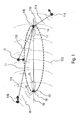
- FIG 1 Such a barrier is intended to constitute a perimetric detection zone 11 surrounding the geographical area whose access is to be controlled. Its main role is to detect the entry of objects 12 in the detection zone 11 and then possibly to specify the evolution parameters of the detected object, the purpose being to trigger an alarm in case of illegal entry of a object in this area, and this with the best possible reliability.
- a sensitive geographical area 61 around a building 65, bordering a hill 63 and backed by a zone planted with trees 64 for example, can in this way be protected against intrusions. It suffices for that, as illustrated by figure 6 , to implement a set of barriers 62 along the perimeter that defines the area to be protected.
- the implementation of such a barrier mainly requires the use of transmission means 13 and reception 14.
- the transmission means 13 have the main feature of being equipped with a directional antenna whose main lobe 15 of the radiation pattern makes it possible to cover, as selectively as possible, the range of space which forms the detection zone 11.
- the receiving means 14 also comprises a directional antenna whose radiation pattern 17 points towards the means emission in the direction 16 which materializes the axis of the barrier.
- Such a barrier has the advantage of being inexpensive in terms of the means used.
- the shape and the length of the barrier depend in particular on the radiation patterns of the antennas used as well as on the power characteristics of the transmitter 13 and the situation of the transmitter. transmitter 13 and receiver 14.
- the transmitter and the receiver at the top of mats or towers, as shown in FIG. figure 4 or 5 .
- this zone may comprise elements of relief and vegetation, such as trees for example, the frequency of The emission of the emitter constituting such a barrier is generally in the VHF or UHF range.
- this rate of false alarms is mainly due to the presence of secondary lobes in the radiation patterns of the directional antennas of the transmitting means 13 and the receiving means 14.
- the main source of false alarm lies in the radiation of a part of the wave emitted through the side lobes 18 of the antenna. This radiation is naturally directed in a direction different from the axis pointed by the main lobe and may be reflected by objects well outside the barrier area. This part 19 of the transmitted wave can therefore be reflected to the receiver 14 by an object 110 moving out of the area to be protected.
- the wave 111 thus reflected is detected at the receiver 14 in the same way as the wave 113 from the wave 112 emitted by the main lobe and reflected by an object 12 seeking to cross the barrier.
- the object 110 will unfairly be detected as an object attempting to cross the barrier and will be the cause of a false alarm
- the main source of false alarm resides in the reception of the reflected waves 115 by any object 114 located at the rear of the reception means 14 and issuing from the wave 112 emitted by the main lobe.
- These reflected waves although coming from an object 114 moving out of the zone to be protected, without attempting to cross the barrier, are picked up by the side lobes 116 of the receiving antenna.
- the object 114 will be unjustly detected as an object attempting to cross the barrier and will be the cause of a false alarm.
- the bistatic barrier according to the invention has main transmission means 13 capable of emitting the wave 112 which constitutes the fence.
- these means comprise an antenna whose diagram 21 is directional, the main lobe of this diagram being directed towards the receiving means 14.
- the bistatic barrier according to the invention also comprises auxiliary transmission means that can emit a wave in a non-directive manner.
- These second means comprise an antenna provided with a non-directional radiation pattern 22, omnidirectional for example.
- these two transmission means may for example be totally separate. They can also be made from a single transmitter provided with two antennas, one directive and the other non-directive, and switching means allowing it to transmit on one or the other antennas.
- the bistatic barrier according to the invention also comprises receiving means 14 provided with an antenna having a directional radiation pattern, whose main lobe 23 is oriented substantially in the direction of the main lobe 21 of the transmitting directive antenna.
- the problem posed by the presence of secondary lobes on the radiation pattern of the directional transmitting antenna can be advantageously solved by the auxiliary transmission means.
- the reception means perform the comparison of the levels of the signal coming from the directional emission and the level of the signal coming from the non-directive emission. Depending on the mode of operation of the transmitting means, these two signals are received simultaneously or one after the other.
- the signal coming from the main transmission, via the directional antenna is considered to have originated from a transmission through the main lobe oriented in the direction to be protected, or from transmission through a secondary lobe oriented in a direction not of interest in terms of protection.
- the comparison relates to the relative levels of the signals received.
- figure 3 illustrates how the respective gains of directional and non-directive transmit antennas can be defined, for example, in the context of the invention.
- the figure 3 represents on the same graph, as a function of the azimuth, the gain curve 31 of the directional antenna the gain curve 32 of the non-directive antenna.
- the azimuth 0 ° here represents the direction pointed by the main lobe of the directional antenna 32.
- the main antenna, directive is conventionally defined by the width of its main lobe 33, at -3 dB of the maximum gain G 1 , as well as by the presence of secondary lobes 34 and 35.
- the auxiliary antenna, omnidirectional is as for it characterized by a curve of gain of constant value G 2 .
- the two gain curves are defined so that the gain G 2 of the omnidirectional antenna is smaller than the gain G 1 -3 dB which corresponds to the minimum gain of the antenna in the space covered by the main lobe 33, and greater than the gain of the directional antenna in the direction of the sidelobes 34 and 35.
- the signal level from the main directional emission is greater than the signal level from the non-directive auxiliary transmission, the detected signal is considered to correspond to an object 12 having entered the barrier.
- the signal level from the main directional emission is lower than the signal level from the non-directive auxiliary transmission, the detected signal is considered a spurious signal corresponding to a non-threatening object 110 moving out of the barrier. .
- the figure 2 illustrates the particular case of a non-threatening object 110 reflecting waves 24 and 25 coming from the omnidirectional wave 26 and from the directional wave 27 emitted by a secondary lobe 18.
- This particular case of echo at the origin of a false intrusion alarm in the existing bistatic barriers is processed by the receiving means 14 of the barrier according to the invention by comparing the relative levels of the waves 24 and 25.
- the level of the main wave 25 reflected by the object 110 is greater, because of the respective gains of the transmitting antennas, at the level of the auxiliary reflected wave.
- the detected echo will be identified as a parasitic echo not to be taken into account.
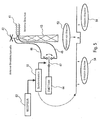
- FIG. 4 This figure illustrates a particular embodiment of the barrier according to the invention.
- the figure 4 represents only the structure of the transmitting means, the receiving means being constituted analogously.
- the transmission means consist of a directional antenna 41 and a non-directive antenna 42 mounted on a tower 43. These two antennas are connected to a single transmitter 44 by the intermediate cables 45 and 46 and controllable switching means 47.
- the transmitter produces for example a UHF CW wave. Switching the CW wave to one or the other of the antennas is provided by synchronization means which define the sequencing chosen to transmit on one or the other antenna. In the example illustrated by the figure 4 the CW wave is emitted alternately on one of the antennas and on the other.
- the switching period is chosen so that the signals received by each of the antennas can be compared even in the case where the object at the origin of these signals moves.
- the signals emanating from the transmitted CW wave are picked up by a reception receiving antenna not shown in the figure.
- This receiving antenna is similar to the transmitting directive antenna 41. It is also mounted on a pylon and is oriented towards the transmitting directive antenna 41.
- This first embodiment has the advantage of setting it performs a simple, periodic sequencing and can operate autonomously independently of the processing performed on the received signals.
- the transmission means thus operate automatically.
- the wave is emitted periodically by the omnidirectional antenna, the presence of the barrier is more easily detectable. This is why we can prefer another embodiment of the transmission means, such as, for example, that described in the figure 5 .
- the transmission means implemented in the embodiment of the figure 5 like those of the figure 4 , a directional antenna 41 and a non-directive antenna 42, omnidirectional for example, both mounted on a pylon 43 and connected to a transmitter 44, through a switch 47 by cables 45 and 46.
- the switch 47 is actuated by synchronization means 51 which receive information from the receiving means constituting the barrier, the receiver 52 for example.
- the synchronization means actuate the switch 47 asynchronously, when a risk of false intrusion alarm exists.
- the non-directive auxiliary transmission 53 can thus be controlled when the reception means have detected a signal coming from an object likely to attempt an intrusion beyond the fence.
- transmission means comprising two antennas, a main antenna, directive, and a non-directive auxiliary antenna, each antenna having a gain defined in the different directions of space
- each antenna having a gain defined in the different directions of space
- This advantageous characteristic is completed according to the invention by the integration in the reception means means capable of detecting and suppressing the signals received by the receiving antenna through its side lobes.
- These means implement known methods, not developed here, processing received signals, conventionally used in particular in radar to neutralize the actions of jamming radar by the antenna side lobes. Among these methods, mention may be made of the SLS (side lobe suppression) or OLS (side lobe opposition) type processes.
Landscapes
- Engineering & Computer Science (AREA)
- Radar, Positioning & Navigation (AREA)
- Remote Sensing (AREA)
- General Physics & Mathematics (AREA)
- Physics & Mathematics (AREA)
- Theoretical Computer Science (AREA)
- Computer Networks & Wireless Communication (AREA)
- Computer Hardware Design (AREA)
- General Engineering & Computer Science (AREA)
- Computer Vision & Pattern Recognition (AREA)
- Software Systems (AREA)
- Artificial Intelligence (AREA)
- Computer Security & Cryptography (AREA)
- Human Computer Interaction (AREA)
- Burglar Alarm Systems (AREA)
- Radar Systems Or Details Thereof (AREA)
- Control Of High-Frequency Heating Circuits (AREA)
- Elimination Of Static Electricity (AREA)
- Photometry And Measurement Of Optical Pulse Characteristics (AREA)
- Details Of Aerials (AREA)
Claims (9)
- Bistatische radioelektrische Detektionsbarriere, die Mittel (13) zum Emittieren von wenigstens einer Welle über eine gerichtete Antenne (21) sowie Mittel zum Empfangen von Signalen über eine in die Emissionsrichtung zeigende gerichtete Antenne (23) umfasst, dadurch gekennzeichnet, dass sie darüber hinaus Mittel zum Emittieren einer Welle über eine ungerichtete Antenne (22) und Mittel zum Vergleichen der relativen Pegel der Echos, die von der Welle kommen, die von der gerichteten Sendeantenne emittiert wird, und von Echos (24) umfasst, die von der Welle kommen, die von der ungerichteten Emissionsantenne emittiert wurde, wobei anhand des Ergebnisses des Vergleichs die Echos (25) erkannt werden können, die von einer Welle kommen, die in der Richtung der Sekundärkeulen (18) der gerichteten Sendeantenne emittiert wurde.
- Vorrichtung nach Anspruch 1, bei der die über die gerichteten (41) und die ungerichteten (42) Antennen emittierten Wellen CW-Wellen sind.
- Vorrichtung nach einem der Ansprüche 1 bis 2, die darüber hinaus Mittel zum Unterdrücken der Echos umfasst, die von den Empfangsmitteln über die Sekundärkeulen der gerichteten Empfangsantenne empfangen werden.
- Vorrichtung nach einem der Ansprüche 1 bis 3, bei der der Wert der Verstärkung G2 (32) der ungerichteten Sendeantenne in der Richtung, in die die Sekundärkeulen der gerichteten Sendeantenne zeigen, zwischen dem Maximalwert G3 (34, 35) der Verstärkung der gerichteten Sendeantenne in der Richtung der Sekundärkeulen (18) und einem Wert liegt, der gleich der maximalen Verstärkung G1 (33) derselben Antenne in der Richtung der Hauptkeule minus 3 dB ist.
- Vorrichtung nach einem der Ansprüche 1 bis 4, bei der die Mittel (48, 47, 41) zum Emittieren der gerichteten Welle und die Mittel (48, 47, 42) zum Emittieren der ungerichteten Welle von einem periodischen Signal so synchronisiert (48) werden, dass abwechselnd eine gerichtete Welle (1) und eine ungerichtete Welle (2) emittiert werden.
- Vorrichtung nach Anspruch 5, bei der die abwechselnde Emission einer gerichteten Welle (1) und einer ungerichteten Welle (2) erfolgt, wenn die Empfangsmittel (52) ein Eindringen entdecken, wobei die Emission einer gerichteten Welle (1) immer in Abwesenheit einer Erkennung erfolgt.
- Vorrichtung nach einem der Ansprüche 1 bis 4, bei der die Mittel zum Emittieren der gerichteten Welle und die Mittel zum Emittieren der ungerichteten Welle getrennt sind und gleichzeitig Wellen mit separaten Frequenzen emittieren.
- Vorrichtung nach einem der Ansprüche 2 bis 7, bei der die Frequenz der gerichteten CW-Welle im Laufe der Zeit variieren kann.
- Vorrichtung nach einem der Ansprüche 2 bis 7, bei der die Mittel zum Emittieren von wenigstens einer gerichteten Welle gleichzeitig zwei CW-Wellen von unterschiedlichen Frequenzen emittieren.
Applications Claiming Priority (2)
| Application Number | Priority Date | Filing Date | Title |
|---|---|---|---|
| FR0507325A FR2888332B1 (fr) | 2005-07-08 | 2005-07-08 | Dispositif radioelectrique bistatique pour realiser une barriere de detection d'instructions |
| PCT/EP2006/063791 WO2007006678A1 (fr) | 2005-07-08 | 2006-07-03 | Dispositif radioelectrique bistatique pour realiser une barriere de detection d'intrusions |
Publications (2)
| Publication Number | Publication Date |
|---|---|
| EP1984751A1 EP1984751A1 (de) | 2008-10-29 |
| EP1984751B1 true EP1984751B1 (de) | 2010-08-25 |
Family
ID=36129758
Family Applications (1)
| Application Number | Title | Priority Date | Filing Date |
|---|---|---|---|
| EP06777547A Not-in-force EP1984751B1 (de) | 2005-07-08 | 2006-07-03 | Bistatische radioelektrische einrichtung zur herstellung einer eindringdetektionsbarriere |
Country Status (10)
| Country | Link |
|---|---|
| US (1) | US20090140922A1 (de) |
| EP (1) | EP1984751B1 (de) |
| AT (1) | ATE479114T1 (de) |
| CA (1) | CA2626340A1 (de) |
| DE (1) | DE602006016495D1 (de) |
| ES (1) | ES2352797T3 (de) |
| FR (1) | FR2888332B1 (de) |
| IL (1) | IL188652A0 (de) |
| NO (1) | NO20080666L (de) |
| WO (1) | WO2007006678A1 (de) |
Families Citing this family (2)
| Publication number | Priority date | Publication date | Assignee | Title |
|---|---|---|---|---|
| US9365126B2 (en) * | 2013-05-10 | 2016-06-14 | Qualcomm Incorporated | System and method for detecting the presence of a moving object below a vehicle |
| US10061018B1 (en) * | 2015-02-19 | 2018-08-28 | Zain Naboulsi | System for identifying drones |
Family Cites Families (23)
| Publication number | Priority date | Publication date | Assignee | Title |
|---|---|---|---|---|
| US4010469A (en) * | 1951-06-20 | 1977-03-01 | The Rand Corporation | Interference suppression |
| US3202990A (en) * | 1959-05-04 | 1965-08-24 | Gen Electric | Intermediate frequency side-lobe canceller |
| US4023172A (en) * | 1959-12-17 | 1977-05-10 | Numax Electronics Incorporated | Monopulse system for cancellation of side lobe effects |
| US3094695A (en) * | 1960-03-23 | 1963-06-18 | Sperry Rand Corp | Antenna side lobe suppression system |
| US4044359A (en) * | 1962-01-09 | 1977-08-23 | General Electric Company | Multiple intermediate frequency side-lobe canceller |
| US4146889A (en) * | 1972-01-20 | 1979-03-27 | Technology Service Corporation | Method and apparatus for sidelobe reduction in radar |
| US5291209A (en) * | 1973-11-02 | 1994-03-01 | Hughes Aircraft Company | Coherent side lobe canceler |
| US3881177A (en) * | 1974-03-12 | 1975-04-29 | Us Army | Frequency agile-baseband sidelobe canceller |
| US3938153A (en) * | 1974-08-16 | 1976-02-10 | The United States Of America As Represented By The Secretary Of The Navy | Sidelobe canceller system |
| DE2450732C3 (de) * | 1974-10-25 | 1979-01-04 | Licentia Patent-Verwaltungs-Gmbh, 6000 Frankfurt | Überwachungssystem mit nach dem Rückstrahlverfahren und als Schranke arbeitendem Sensor |
| US5162805A (en) * | 1975-02-19 | 1992-11-10 | The United States Of America As Represented By The Secretary Of The Navy | Frequency diversity sidelobe canceller |
| US4367472A (en) * | 1979-09-28 | 1983-01-04 | Siemens Aktiengesellschaft | Circuit arrangement for side lobe suppression in radar apparatuses |
| US4298872A (en) * | 1980-05-27 | 1981-11-03 | Hughes Aircraft Company | Sidelobe blanking system |
| US4595924A (en) * | 1981-10-06 | 1986-06-17 | General Dynamics Electronics | Intruder detection radar system and automatic nulling antenna array |
| US4573051A (en) * | 1982-08-02 | 1986-02-25 | Selenia S.P.A. | Adaptive system for suppressing interferences from directional jammers in electronically or mechanically scanning radar |
| US4595925A (en) * | 1983-03-28 | 1986-06-17 | The United States Of America As Represented By The Secretary Of The Navy | Altitude determining radar using multipath discrimination |
| DE3414158A1 (de) * | 1984-04-14 | 1985-10-24 | Licentia Patent-Verwaltungs-Gmbh, 6000 Frankfurt | Anordnung fuer ein gelaendefolgeradar |
| US5045858A (en) * | 1989-08-16 | 1991-09-03 | Cubic Defense Systems, Inc. | Sidelobe identification and discrimination system with signal multiplexer-separator |
| US4959653A (en) * | 1989-08-23 | 1990-09-25 | Massachusetts Institute Of Technology | Adaptive sidelobe blanker |
| US5173704A (en) * | 1991-10-03 | 1992-12-22 | The Boeing Company | Air turbulence detection using bi-static CW Doppler radar |
| NL9302002A (nl) * | 1993-11-19 | 1995-06-16 | Hollandse Signaalapparaten Bv | Radarapparaat voorzien van ECCM voorzieningen. |
| GB2303266B (en) * | 1995-07-07 | 2000-01-19 | Gec Marconi Avionics Holdings | Radar apparatus |
| US6697009B2 (en) * | 2001-06-15 | 2004-02-24 | Lockheed Martin Corporation | Adaptive digital beamforming architecture for target detection and angle estimation in multiple mainlobe and sidelobe jamming |
-
2005
- 2005-07-08 FR FR0507325A patent/FR2888332B1/fr not_active Expired - Fee Related
-
2006
- 2006-07-03 AT AT06777547T patent/ATE479114T1/de not_active IP Right Cessation
- 2006-07-03 US US11/995,094 patent/US20090140922A1/en not_active Abandoned
- 2006-07-03 ES ES06777547T patent/ES2352797T3/es active Active
- 2006-07-03 WO PCT/EP2006/063791 patent/WO2007006678A1/fr active Application Filing
- 2006-07-03 DE DE602006016495T patent/DE602006016495D1/de active Active
- 2006-07-03 CA CA002626340A patent/CA2626340A1/en not_active Abandoned
- 2006-07-03 EP EP06777547A patent/EP1984751B1/de not_active Not-in-force
-
2008
- 2008-01-08 IL IL188652A patent/IL188652A0/en unknown
- 2008-02-05 NO NO20080666A patent/NO20080666L/no not_active Application Discontinuation
Also Published As
| Publication number | Publication date |
|---|---|
| ATE479114T1 (de) | 2010-09-15 |
| WO2007006678A1 (fr) | 2007-01-18 |
| CA2626340A1 (en) | 2007-01-18 |
| EP1984751A1 (de) | 2008-10-29 |
| US20090140922A1 (en) | 2009-06-04 |
| WO2007006678A8 (fr) | 2008-09-04 |
| DE602006016495D1 (de) | 2010-10-07 |
| NO20080666L (no) | 2008-04-01 |
| IL188652A0 (en) | 2008-08-07 |
| FR2888332A1 (fr) | 2007-01-12 |
| ES2352797T3 (es) | 2011-02-23 |
| FR2888332B1 (fr) | 2007-11-02 |
Similar Documents
| Publication | Publication Date | Title |
|---|---|---|
| EP0264331B1 (de) | Verfahren zur Schlagfeld-Freund-Feind-Kennung und System zum Ausführen davon | |
| US6466157B1 (en) | Electronic fence using high-resolution millimeter-wave radar in conjunction with multiple passive reflectors | |
| US8917199B2 (en) | Subterranean image generating device and associated method | |
| EP2831615B1 (de) | Vorrichtung für aktive und passive elektromagnetische detektion mit geringer wahrscheinlichkeit von unterbrechungen | |
| EP3074786B1 (de) | Antikollisionsradar, insbesondere für ein flugzeug beim rollen, und kollisionsschutzsystem | |
| FR2910161A1 (fr) | Systeme goniometrique de mini capteurs doppler en reseaux pour la surveillance de perimetres | |
| FR2953297A1 (fr) | Reseau de bases radars uhf pour la protection de zones sensibles contre les intrusions | |
| JP2010096757A (ja) | 障害物検出および警告のためのシステムおよび方法 | |
| EP2472215B1 (de) | Verfahren und Vorrichtung zur Neutralisierung eines Ziels | |
| FR2709835A1 (fr) | Procédé d'extraction de cibles d'un signal radar et radar susceptible de mettre en Óoeuvre ledit procédé. | |
| EP1984751B1 (de) | Bistatische radioelektrische einrichtung zur herstellung einer eindringdetektionsbarriere | |
| EP3485292B1 (de) | Verfahren und vorrichtung zur bestimmung einer geografischen, operationalen, durch einen sensor beobachteten zone | |
| FR2974933A1 (fr) | Systeme pour detecter une intrusion et procede | |
| WO2019122763A1 (fr) | Systeme de detection interferometrique de foudre | |
| EP3111247B1 (de) | Zur ausrüstung eines küstenüberwachungssystems geeignete radarvorrichtung und küstenüberwachungssystem mit solch einer vorrichtung | |
| FR2953939A1 (fr) | Systeme radar uhf pour mettre en oeuvre un procede d'elimination d'un fouillis de vegetation | |
| WO2012123648A1 (fr) | Système intégré de lutte contre des engins explosifs improvisés | |
| CA2830604C (fr) | Procede et systeme de detection de signaux de diffusion emis par des sources terrestres et recus par un satellite | |
| EP3896484A1 (de) | Sekundärer meta-radar | |
| US20080122678A1 (en) | Multi Purpose Radar Surveillance System | |
| FR2732469A1 (fr) | Dispositif utilisant une antenne auxiliaire equipee d'un filtre spatial adaptatif pour l'embrouillage d'une antenne principale associee, et son procede de mise en oeuvre | |
| FR2948194A1 (fr) | Systeme radar complementaire pour la detection de cibles evoluant dans un champ d'eoliennes | |
| EP0585163B1 (de) | Gegen Eindringen geschütztes Freund-Feind-Kennungssystem mit Unterscheidungsfähigkeit | |
| FR2709010A1 (fr) | Installation pour la détection d'intrusions du type utilisant des câbles rayonnants noyés dans le sol. | |
| FR2948198A1 (fr) | Systeme radar complementaire pour la detection de cibles evoluant a basse altitude au dessus d'un champ d'eoliennes |
Legal Events
| Date | Code | Title | Description |
|---|---|---|---|
| PUAI | Public reference made under article 153(3) epc to a published international application that has entered the european phase |
Free format text: ORIGINAL CODE: 0009012 |
|
| 17P | Request for examination filed |
Effective date: 20080208 |
|
| AK | Designated contracting states |
Kind code of ref document: A1 Designated state(s): AT BE BG CH CY CZ DE DK EE ES FI FR GB GR HU IE IS IT LI LT LU LV MC NL PL PT RO SE SI SK TR |
|
| 17Q | First examination report despatched |
Effective date: 20091118 |
|
| GRAP | Despatch of communication of intention to grant a patent |
Free format text: ORIGINAL CODE: EPIDOSNIGR1 |
|
| DAX | Request for extension of the european patent (deleted) | ||
| GRAS | Grant fee paid |
Free format text: ORIGINAL CODE: EPIDOSNIGR3 |
|
| GRAA | (expected) grant |
Free format text: ORIGINAL CODE: 0009210 |
|
| AK | Designated contracting states |
Kind code of ref document: B1 Designated state(s): AT BE BG CH CY CZ DE DK EE ES FI FR GB GR HU IE IS IT LI LT LU LV MC NL PL PT RO SE SI SK TR |
|
| REG | Reference to a national code |
Ref country code: GB Ref legal event code: FG4D Free format text: NOT ENGLISH |
|
| REG | Reference to a national code |
Ref country code: CH Ref legal event code: EP |
|
| REG | Reference to a national code |
Ref country code: IE Ref legal event code: FG4D Free format text: LANGUAGE OF EP DOCUMENT: FRENCH |
|
| REF | Corresponds to: |
Ref document number: 602006016495 Country of ref document: DE Date of ref document: 20101007 Kind code of ref document: P |
|
| REG | Reference to a national code |
Ref country code: NL Ref legal event code: T3 |
|
| LTIE | Lt: invalidation of european patent or patent extension |
Effective date: 20100825 |
|
| PG25 | Lapsed in a contracting state [announced via postgrant information from national office to epo] |
Ref country code: FI Free format text: LAPSE BECAUSE OF FAILURE TO SUBMIT A TRANSLATION OF THE DESCRIPTION OR TO PAY THE FEE WITHIN THE PRESCRIBED TIME-LIMIT Effective date: 20100825 Ref country code: AT Free format text: LAPSE BECAUSE OF FAILURE TO SUBMIT A TRANSLATION OF THE DESCRIPTION OR TO PAY THE FEE WITHIN THE PRESCRIBED TIME-LIMIT Effective date: 20100825 Ref country code: LT Free format text: LAPSE BECAUSE OF FAILURE TO SUBMIT A TRANSLATION OF THE DESCRIPTION OR TO PAY THE FEE WITHIN THE PRESCRIBED TIME-LIMIT Effective date: 20100825 |
|
| REG | Reference to a national code |
Ref country code: ES Ref legal event code: FG2A Effective date: 20110211 |
|
| PG25 | Lapsed in a contracting state [announced via postgrant information from national office to epo] |
Ref country code: SI Free format text: LAPSE BECAUSE OF FAILURE TO SUBMIT A TRANSLATION OF THE DESCRIPTION OR TO PAY THE FEE WITHIN THE PRESCRIBED TIME-LIMIT Effective date: 20100825 Ref country code: PT Free format text: LAPSE BECAUSE OF FAILURE TO SUBMIT A TRANSLATION OF THE DESCRIPTION OR TO PAY THE FEE WITHIN THE PRESCRIBED TIME-LIMIT Effective date: 20101227 Ref country code: PL Free format text: LAPSE BECAUSE OF FAILURE TO SUBMIT A TRANSLATION OF THE DESCRIPTION OR TO PAY THE FEE WITHIN THE PRESCRIBED TIME-LIMIT Effective date: 20100825 Ref country code: IS Free format text: LAPSE BECAUSE OF FAILURE TO SUBMIT A TRANSLATION OF THE DESCRIPTION OR TO PAY THE FEE WITHIN THE PRESCRIBED TIME-LIMIT Effective date: 20101225 Ref country code: CY Free format text: LAPSE BECAUSE OF FAILURE TO SUBMIT A TRANSLATION OF THE DESCRIPTION OR TO PAY THE FEE WITHIN THE PRESCRIBED TIME-LIMIT Effective date: 20100825 Ref country code: BG Free format text: LAPSE BECAUSE OF FAILURE TO SUBMIT A TRANSLATION OF THE DESCRIPTION OR TO PAY THE FEE WITHIN THE PRESCRIBED TIME-LIMIT Effective date: 20101125 |
|
| REG | Reference to a national code |
Ref country code: IE Ref legal event code: FD4D |
|
| PG25 | Lapsed in a contracting state [announced via postgrant information from national office to epo] |
Ref country code: SE Free format text: LAPSE BECAUSE OF FAILURE TO SUBMIT A TRANSLATION OF THE DESCRIPTION OR TO PAY THE FEE WITHIN THE PRESCRIBED TIME-LIMIT Effective date: 20100825 Ref country code: LV Free format text: LAPSE BECAUSE OF FAILURE TO SUBMIT A TRANSLATION OF THE DESCRIPTION OR TO PAY THE FEE WITHIN THE PRESCRIBED TIME-LIMIT Effective date: 20100825 Ref country code: GR Free format text: LAPSE BECAUSE OF FAILURE TO SUBMIT A TRANSLATION OF THE DESCRIPTION OR TO PAY THE FEE WITHIN THE PRESCRIBED TIME-LIMIT Effective date: 20101126 |
|
| PG25 | Lapsed in a contracting state [announced via postgrant information from national office to epo] |
Ref country code: IE Free format text: LAPSE BECAUSE OF FAILURE TO SUBMIT A TRANSLATION OF THE DESCRIPTION OR TO PAY THE FEE WITHIN THE PRESCRIBED TIME-LIMIT Effective date: 20100825 Ref country code: DK Free format text: LAPSE BECAUSE OF FAILURE TO SUBMIT A TRANSLATION OF THE DESCRIPTION OR TO PAY THE FEE WITHIN THE PRESCRIBED TIME-LIMIT Effective date: 20100825 |
|
| PG25 | Lapsed in a contracting state [announced via postgrant information from national office to epo] |
Ref country code: RO Free format text: LAPSE BECAUSE OF FAILURE TO SUBMIT A TRANSLATION OF THE DESCRIPTION OR TO PAY THE FEE WITHIN THE PRESCRIBED TIME-LIMIT Effective date: 20100825 Ref country code: SK Free format text: LAPSE BECAUSE OF FAILURE TO SUBMIT A TRANSLATION OF THE DESCRIPTION OR TO PAY THE FEE WITHIN THE PRESCRIBED TIME-LIMIT Effective date: 20100825 Ref country code: EE Free format text: LAPSE BECAUSE OF FAILURE TO SUBMIT A TRANSLATION OF THE DESCRIPTION OR TO PAY THE FEE WITHIN THE PRESCRIBED TIME-LIMIT Effective date: 20100825 Ref country code: CZ Free format text: LAPSE BECAUSE OF FAILURE TO SUBMIT A TRANSLATION OF THE DESCRIPTION OR TO PAY THE FEE WITHIN THE PRESCRIBED TIME-LIMIT Effective date: 20100825 |
|
| PLBE | No opposition filed within time limit |
Free format text: ORIGINAL CODE: 0009261 |
|
| STAA | Information on the status of an ep patent application or granted ep patent |
Free format text: STATUS: NO OPPOSITION FILED WITHIN TIME LIMIT |
|
| 26N | No opposition filed |
Effective date: 20110526 |
|
| REG | Reference to a national code |
Ref country code: DE Ref legal event code: R097 Ref document number: 602006016495 Country of ref document: DE Effective date: 20110526 |
|
| BERE | Be: lapsed |
Owner name: THALES Effective date: 20110731 |
|
| PG25 | Lapsed in a contracting state [announced via postgrant information from national office to epo] |
Ref country code: MC Free format text: LAPSE BECAUSE OF NON-PAYMENT OF DUE FEES Effective date: 20110731 |
|
| REG | Reference to a national code |
Ref country code: CH Ref legal event code: PL |
|
| PG25 | Lapsed in a contracting state [announced via postgrant information from national office to epo] |
Ref country code: BE Free format text: LAPSE BECAUSE OF NON-PAYMENT OF DUE FEES Effective date: 20110731 Ref country code: LI Free format text: LAPSE BECAUSE OF NON-PAYMENT OF DUE FEES Effective date: 20110731 Ref country code: CH Free format text: LAPSE BECAUSE OF NON-PAYMENT OF DUE FEES Effective date: 20110731 |
|
| PGFP | Annual fee paid to national office [announced via postgrant information from national office to epo] |
Ref country code: GB Payment date: 20120627 Year of fee payment: 7 |
|
| PGFP | Annual fee paid to national office [announced via postgrant information from national office to epo] |
Ref country code: IT Payment date: 20120714 Year of fee payment: 7 Ref country code: FR Payment date: 20120719 Year of fee payment: 7 |
|
| PGFP | Annual fee paid to national office [announced via postgrant information from national office to epo] |
Ref country code: NL Payment date: 20120710 Year of fee payment: 7 |
|
| PG25 | Lapsed in a contracting state [announced via postgrant information from national office to epo] |
Ref country code: LU Free format text: LAPSE BECAUSE OF NON-PAYMENT OF DUE FEES Effective date: 20110703 |
|
| PG25 | Lapsed in a contracting state [announced via postgrant information from national office to epo] |
Ref country code: TR Free format text: LAPSE BECAUSE OF FAILURE TO SUBMIT A TRANSLATION OF THE DESCRIPTION OR TO PAY THE FEE WITHIN THE PRESCRIBED TIME-LIMIT Effective date: 20100825 |
|
| PG25 | Lapsed in a contracting state [announced via postgrant information from national office to epo] |
Ref country code: HU Free format text: LAPSE BECAUSE OF FAILURE TO SUBMIT A TRANSLATION OF THE DESCRIPTION OR TO PAY THE FEE WITHIN THE PRESCRIBED TIME-LIMIT Effective date: 20100825 |
|
| PGFP | Annual fee paid to national office [announced via postgrant information from national office to epo] |
Ref country code: ES Payment date: 20130628 Year of fee payment: 8 Ref country code: DE Payment date: 20130626 Year of fee payment: 8 |
|
| REG | Reference to a national code |
Ref country code: NL Ref legal event code: V1 Effective date: 20140201 |
|
| GBPC | Gb: european patent ceased through non-payment of renewal fee |
Effective date: 20130703 |
|
| REG | Reference to a national code |
Ref country code: FR Ref legal event code: ST Effective date: 20140331 |
|
| PG25 | Lapsed in a contracting state [announced via postgrant information from national office to epo] |
Ref country code: NL Free format text: LAPSE BECAUSE OF NON-PAYMENT OF DUE FEES Effective date: 20140201 Ref country code: GB Free format text: LAPSE BECAUSE OF NON-PAYMENT OF DUE FEES Effective date: 20130703 |
|
| PG25 | Lapsed in a contracting state [announced via postgrant information from national office to epo] |
Ref country code: IT Free format text: LAPSE BECAUSE OF NON-PAYMENT OF DUE FEES Effective date: 20130703 Ref country code: FR Free format text: LAPSE BECAUSE OF NON-PAYMENT OF DUE FEES Effective date: 20130731 |
|
| REG | Reference to a national code |
Ref country code: DE Ref legal event code: R119 Ref document number: 602006016495 Country of ref document: DE |
|
| PG25 | Lapsed in a contracting state [announced via postgrant information from national office to epo] |
Ref country code: DE Free format text: LAPSE BECAUSE OF NON-PAYMENT OF DUE FEES Effective date: 20150203 |
|
| REG | Reference to a national code |
Ref country code: DE Ref legal event code: R119 Ref document number: 602006016495 Country of ref document: DE Effective date: 20150203 |
|
| REG | Reference to a national code |
Ref country code: ES Ref legal event code: FD2A Effective date: 20150828 |
|
| PG25 | Lapsed in a contracting state [announced via postgrant information from national office to epo] |
Ref country code: ES Free format text: LAPSE BECAUSE OF NON-PAYMENT OF DUE FEES Effective date: 20140704 |