EP1984152B1 - Method for producing a multi-layer coating for razor blades - Google Patents
Method for producing a multi-layer coating for razor blades Download PDFInfo
- Publication number
- EP1984152B1 EP1984152B1 EP07750410.8A EP07750410A EP1984152B1 EP 1984152 B1 EP1984152 B1 EP 1984152B1 EP 07750410 A EP07750410 A EP 07750410A EP 1984152 B1 EP1984152 B1 EP 1984152B1
- Authority
- EP
- European Patent Office
- Prior art keywords
- layer
- substrate
- containing material
- titanium
- titanium containing
- Prior art date
- Legal status (The legal status is an assumption and is not a legal conclusion. Google has not performed a legal analysis and makes no representation as to the accuracy of the status listed.)
- Active
Links
Images

Classifications
-
- B—PERFORMING OPERATIONS; TRANSPORTING
- B26—HAND CUTTING TOOLS; CUTTING; SEVERING
- B26B—HAND-HELD CUTTING TOOLS NOT OTHERWISE PROVIDED FOR
- B26B21/00—Razors of the open or knife type; Safety razors or other shaving implements of the planing type; Hair-trimming devices involving a razor-blade; Equipment therefor
- B26B21/54—Razor-blades
- B26B21/58—Razor-blades characterised by the material
- B26B21/60—Razor-blades characterised by the material by the coating material
-
- C—CHEMISTRY; METALLURGY
- C23—COATING METALLIC MATERIAL; COATING MATERIAL WITH METALLIC MATERIAL; CHEMICAL SURFACE TREATMENT; DIFFUSION TREATMENT OF METALLIC MATERIAL; COATING BY VACUUM EVAPORATION, BY SPUTTERING, BY ION IMPLANTATION OR BY CHEMICAL VAPOUR DEPOSITION, IN GENERAL; INHIBITING CORROSION OF METALLIC MATERIAL OR INCRUSTATION IN GENERAL
- C23C—COATING METALLIC MATERIAL; COATING MATERIAL WITH METALLIC MATERIAL; SURFACE TREATMENT OF METALLIC MATERIAL BY DIFFUSION INTO THE SURFACE, BY CHEMICAL CONVERSION OR SUBSTITUTION; COATING BY VACUUM EVAPORATION, BY SPUTTERING, BY ION IMPLANTATION OR BY CHEMICAL VAPOUR DEPOSITION, IN GENERAL
- C23C14/00—Coating by vacuum evaporation, by sputtering or by ion implantation of the coating forming material
- C23C14/02—Pretreatment of the material to be coated
- C23C14/021—Cleaning or etching treatments
- C23C14/022—Cleaning or etching treatments by means of bombardment with energetic particles or radiation
-
- C—CHEMISTRY; METALLURGY
- C23—COATING METALLIC MATERIAL; COATING MATERIAL WITH METALLIC MATERIAL; CHEMICAL SURFACE TREATMENT; DIFFUSION TREATMENT OF METALLIC MATERIAL; COATING BY VACUUM EVAPORATION, BY SPUTTERING, BY ION IMPLANTATION OR BY CHEMICAL VAPOUR DEPOSITION, IN GENERAL; INHIBITING CORROSION OF METALLIC MATERIAL OR INCRUSTATION IN GENERAL
- C23C—COATING METALLIC MATERIAL; COATING MATERIAL WITH METALLIC MATERIAL; SURFACE TREATMENT OF METALLIC MATERIAL BY DIFFUSION INTO THE SURFACE, BY CHEMICAL CONVERSION OR SUBSTITUTION; COATING BY VACUUM EVAPORATION, BY SPUTTERING, BY ION IMPLANTATION OR BY CHEMICAL VAPOUR DEPOSITION, IN GENERAL
- C23C14/00—Coating by vacuum evaporation, by sputtering or by ion implantation of the coating forming material
- C23C14/02—Pretreatment of the material to be coated
- C23C14/024—Deposition of sublayers, e.g. to promote adhesion of the coating
-
- C—CHEMISTRY; METALLURGY
- C23—COATING METALLIC MATERIAL; COATING MATERIAL WITH METALLIC MATERIAL; CHEMICAL SURFACE TREATMENT; DIFFUSION TREATMENT OF METALLIC MATERIAL; COATING BY VACUUM EVAPORATION, BY SPUTTERING, BY ION IMPLANTATION OR BY CHEMICAL VAPOUR DEPOSITION, IN GENERAL; INHIBITING CORROSION OF METALLIC MATERIAL OR INCRUSTATION IN GENERAL
- C23C—COATING METALLIC MATERIAL; COATING MATERIAL WITH METALLIC MATERIAL; SURFACE TREATMENT OF METALLIC MATERIAL BY DIFFUSION INTO THE SURFACE, BY CHEMICAL CONVERSION OR SUBSTITUTION; COATING BY VACUUM EVAPORATION, BY SPUTTERING, BY ION IMPLANTATION OR BY CHEMICAL VAPOUR DEPOSITION, IN GENERAL
- C23C14/00—Coating by vacuum evaporation, by sputtering or by ion implantation of the coating forming material
- C23C14/02—Pretreatment of the material to be coated
- C23C14/027—Graded interfaces
-
- C—CHEMISTRY; METALLURGY
- C23—COATING METALLIC MATERIAL; COATING MATERIAL WITH METALLIC MATERIAL; CHEMICAL SURFACE TREATMENT; DIFFUSION TREATMENT OF METALLIC MATERIAL; COATING BY VACUUM EVAPORATION, BY SPUTTERING, BY ION IMPLANTATION OR BY CHEMICAL VAPOUR DEPOSITION, IN GENERAL; INHIBITING CORROSION OF METALLIC MATERIAL OR INCRUSTATION IN GENERAL
- C23C—COATING METALLIC MATERIAL; COATING MATERIAL WITH METALLIC MATERIAL; SURFACE TREATMENT OF METALLIC MATERIAL BY DIFFUSION INTO THE SURFACE, BY CHEMICAL CONVERSION OR SUBSTITUTION; COATING BY VACUUM EVAPORATION, BY SPUTTERING, BY ION IMPLANTATION OR BY CHEMICAL VAPOUR DEPOSITION, IN GENERAL
- C23C14/00—Coating by vacuum evaporation, by sputtering or by ion implantation of the coating forming material
- C23C14/02—Pretreatment of the material to be coated
- C23C14/028—Physical treatment to alter the texture of the substrate surface, e.g. grinding, polishing
-
- C—CHEMISTRY; METALLURGY
- C23—COATING METALLIC MATERIAL; COATING MATERIAL WITH METALLIC MATERIAL; CHEMICAL SURFACE TREATMENT; DIFFUSION TREATMENT OF METALLIC MATERIAL; COATING BY VACUUM EVAPORATION, BY SPUTTERING, BY ION IMPLANTATION OR BY CHEMICAL VAPOUR DEPOSITION, IN GENERAL; INHIBITING CORROSION OF METALLIC MATERIAL OR INCRUSTATION IN GENERAL
- C23C—COATING METALLIC MATERIAL; COATING MATERIAL WITH METALLIC MATERIAL; SURFACE TREATMENT OF METALLIC MATERIAL BY DIFFUSION INTO THE SURFACE, BY CHEMICAL CONVERSION OR SUBSTITUTION; COATING BY VACUUM EVAPORATION, BY SPUTTERING, BY ION IMPLANTATION OR BY CHEMICAL VAPOUR DEPOSITION, IN GENERAL
- C23C14/00—Coating by vacuum evaporation, by sputtering or by ion implantation of the coating forming material
- C23C14/06—Coating by vacuum evaporation, by sputtering or by ion implantation of the coating forming material characterised by the coating material
- C23C14/0605—Carbon
-
- C—CHEMISTRY; METALLURGY
- C23—COATING METALLIC MATERIAL; COATING MATERIAL WITH METALLIC MATERIAL; CHEMICAL SURFACE TREATMENT; DIFFUSION TREATMENT OF METALLIC MATERIAL; COATING BY VACUUM EVAPORATION, BY SPUTTERING, BY ION IMPLANTATION OR BY CHEMICAL VAPOUR DEPOSITION, IN GENERAL; INHIBITING CORROSION OF METALLIC MATERIAL OR INCRUSTATION IN GENERAL
- C23C—COATING METALLIC MATERIAL; COATING MATERIAL WITH METALLIC MATERIAL; SURFACE TREATMENT OF METALLIC MATERIAL BY DIFFUSION INTO THE SURFACE, BY CHEMICAL CONVERSION OR SUBSTITUTION; COATING BY VACUUM EVAPORATION, BY SPUTTERING, BY ION IMPLANTATION OR BY CHEMICAL VAPOUR DEPOSITION, IN GENERAL
- C23C14/00—Coating by vacuum evaporation, by sputtering or by ion implantation of the coating forming material
- C23C14/22—Coating by vacuum evaporation, by sputtering or by ion implantation of the coating forming material characterised by the process of coating
- C23C14/24—Vacuum evaporation
- C23C14/32—Vacuum evaporation by explosion; by evaporation and subsequent ionisation of the vapours, e.g. ion-plating
- C23C14/325—Electric arc evaporation
-
- C—CHEMISTRY; METALLURGY
- C23—COATING METALLIC MATERIAL; COATING MATERIAL WITH METALLIC MATERIAL; CHEMICAL SURFACE TREATMENT; DIFFUSION TREATMENT OF METALLIC MATERIAL; COATING BY VACUUM EVAPORATION, BY SPUTTERING, BY ION IMPLANTATION OR BY CHEMICAL VAPOUR DEPOSITION, IN GENERAL; INHIBITING CORROSION OF METALLIC MATERIAL OR INCRUSTATION IN GENERAL
- C23C—COATING METALLIC MATERIAL; COATING MATERIAL WITH METALLIC MATERIAL; SURFACE TREATMENT OF METALLIC MATERIAL BY DIFFUSION INTO THE SURFACE, BY CHEMICAL CONVERSION OR SUBSTITUTION; COATING BY VACUUM EVAPORATION, BY SPUTTERING, BY ION IMPLANTATION OR BY CHEMICAL VAPOUR DEPOSITION, IN GENERAL
- C23C28/00—Coating for obtaining at least two superposed coatings either by methods not provided for in a single one of groups C23C2/00 - C23C26/00 or by combinations of methods provided for in subclasses C23C and C25C or C25D
-
- C—CHEMISTRY; METALLURGY
- C23—COATING METALLIC MATERIAL; COATING MATERIAL WITH METALLIC MATERIAL; CHEMICAL SURFACE TREATMENT; DIFFUSION TREATMENT OF METALLIC MATERIAL; COATING BY VACUUM EVAPORATION, BY SPUTTERING, BY ION IMPLANTATION OR BY CHEMICAL VAPOUR DEPOSITION, IN GENERAL; INHIBITING CORROSION OF METALLIC MATERIAL OR INCRUSTATION IN GENERAL
- C23C—COATING METALLIC MATERIAL; COATING MATERIAL WITH METALLIC MATERIAL; SURFACE TREATMENT OF METALLIC MATERIAL BY DIFFUSION INTO THE SURFACE, BY CHEMICAL CONVERSION OR SUBSTITUTION; COATING BY VACUUM EVAPORATION, BY SPUTTERING, BY ION IMPLANTATION OR BY CHEMICAL VAPOUR DEPOSITION, IN GENERAL
- C23C30/00—Coating with metallic material characterised only by the composition of the metallic material, i.e. not characterised by the coating process
- C23C30/005—Coating with metallic material characterised only by the composition of the metallic material, i.e. not characterised by the coating process on hard metal substrates
Definitions
- This invention relates generally to shaving devices, and more specifically to a method of making razor blades having multi-layer coatings.
- the adhesion of a hard carbon material such as amorphous diamond or DLC to a stainless steel substrate can be promoted by providing an undercoat layer of an adhesion promoting material between the substrate and the hard carbon layer. It is known in the art to provide a layer of chromium or niobium containing materials as an adhesion promoting layer. This is describe in US Patent Number 6,684,513 to Clipstone et al.
- a magnetron target (as will be discussed later in the instant application) to provide a niobium layer costs 50% more than a target for a chromium layer and is consequently not preferred for reasons of manufacturing cost
- the use of chromium is well known in the art, it promotes adequate adhesion and it provides a good solution to this problem.
- US Patent No. 6,821,624 describes amorphous carbon covered members having an interlayer comprising at least one element selected from the group consisting of elements in the IVa, Va, VIa and IIIb groups and the IVb group except carbon in the periodic table, or a carbide of at least one element selected from the group, and an amorphous carbon film formed on the interlayer.
- the present invention provides a method of making a razor blade as defined in claim 1. Preferred embodiments of the invention are apparent from the dependent claims.
- a first bias voltage more positive than -700 volts is applied to the razor blade and the razor blade is in a first atmosphere that includes Argon at a pressure less than 6.65 Pa (50 milliTorr).
- the titanium containing material is implanted with carbon to form a partial titanium carbide layer.
- the razor blade is in a second atmosphere that includes Argon at a pressure less than 3.99 Pa (30 milliTorr).
- a second bias voltage more positive than -1500 volts is applied to the razor blade.
- Subsequent layers of hard carbon material and PTFE are applied by well known processes.
- the substrate is typically supplied in an annealed state as an elongated flat strip, wound in a coil and is preferably 0,05mm to 0,1 mm thick, most preferably 0,1 mm, and is preferably 3mm wide but can be from 2mm to 23mm wide.
- the substrate may be perforated as is known in the art.
- the substrate is hardened, again as is known in the art to a hardness 900 on the Vickers scale (Hv).
- the substrate is sharpened to provide a cutting edge having a sharpened tip 20 of radius less than 100 nm and preferably 20-50 nm.
- the sharpened tip has adjacent facets 22 having an included angle less than 30 degrees and preferably 15-20 degrees measured 40 nm from the sharpened tip.
- the sharpening process includes grinding and honing stages and may include a further stropping stage.
- the sharpening process may be performed on both edges of the elongate substrate but is preferably on one edge only.
- As the elongate substrate exits the sharpening process it may be cut into individual razor blades and stacked one on the other, or preferably the elongate substrate is recoiled on to a carrier with the sharpened edge facing outward.
- the substrate is subsequently cleaned by any one of a number of processes known in the art to remove residues from the sharpening process and other contamination. Samples of the substrate are analyzed for cleanliness preferably by a photoelectron emission technique. Suitable measuring equipment is supplied by PET PHOTO EMISSION TECHNOLOGY and is designated SQM300.
- a substrate with an OSEE (optically stimulated electron emission) value at least 450 is adequately clean.
- the magnetron sputtering step is followed by a preferred a-Diamond or amorphous diamond step that deposits a hard carbon material of amorphous diamond on the titanium containing material.
- the hard carbon material may also be Diamond-like Carbon (DLC).
- Two cathodic arc sources are preferably situated such that each carbon beam is approximately normal to one of each facet of the cutting edge. This is the optimum arrangement that will provide hardest coating. Suitable coatings however are achieved with a narrower angle of 60 degrees between the two carbon beams.
- Argon is introduced into the chamber to a pressure of 2.66 mPa to 1.197 Pa (20 microTorr to 9 milliTorr).
- PTFE polytetrafluoroethylene
- a suitable PTFE is DRYFILM LW1200 manufactured by DUPONT, having a molecular weight of 40,000.
- the DRYFILM LW1200 is preferably diluted with alcohol as disclosed in US Patent Application serial number 60/741,144 .
- One of skill in the art will understand other PTFE materials may be employed.
- a razor blade 10 is manufactured generally to the processes described herein. Individual razor blades may be in stack form or the coiled substrate may subsequently uncoiled and cut to a convenient length to form a single razor blade.
- the cutting edge portion of the razor blade 10 has improved resistance to failure by crack propagation compared to known cutting edges of razor blades having chromium coatings between their substrate and hard carbon coatings.
- the use of a titanium containing material on the cutting edge of a razor blade promotes adhesion of the hard carbon material.
- the razor blade has excellent shaving characteristics.
Landscapes
- Chemical & Material Sciences (AREA)
- Engineering & Computer Science (AREA)
- Mechanical Engineering (AREA)
- Chemical Kinetics & Catalysis (AREA)
- Materials Engineering (AREA)
- Metallurgy (AREA)
- Organic Chemistry (AREA)
- Life Sciences & Earth Sciences (AREA)
- Forests & Forestry (AREA)
- Physical Vapour Deposition (AREA)
- Dry Shavers And Clippers (AREA)
Description
- This invention relates generally to shaving devices, and more specifically to a method of making razor blades having multi-layer coatings.
- A razor blade is typically formed of a suitable substrate material, such as stainless steel. A cutting edge is provided to the razor blade, typically by grinding and honing. The cutting edge has a wedge-shaped configuration with a sharpened tip having a radius less than 100 nm, e.g., 20-50 nm. Hard carbon coatings such as amorphous diamond or diamond-like carbon (DLC) material are often used to improve hardness, strength, corrosion resistance and shaving ability. The hard carbon coating maintains the required strength of the ultimate tip while permitting more acutely angled wedge shapes with consequently lower cutting forces to be used. A polytetrafluoroethylene (PTFE) outer layer can be used to provide friction reduction. The adhesion of a hard carbon material such as amorphous diamond or DLC to a stainless steel substrate can be promoted by providing an undercoat layer of an adhesion promoting material between the substrate and the hard carbon layer. It is known in the art to provide a layer of chromium or niobium containing materials as an adhesion promoting layer. This is describe in
US Patent Number 6,684,513 to Clipstone et al. In practice, a magnetron target (as will be discussed later in the instant application) to provide a niobium layer costs 50% more than a target for a chromium layer and is consequently not preferred for reasons of manufacturing cost The use of chromium is well known in the art, it promotes adequate adhesion and it provides a good solution to this problem. -
WO-A-2007/064699 discloses an interlayer between the hard coating (carbon) layer and the substrate (stainless steel) of an razor blade and suitable materials therefore, such as niobium, chromium, titanium, chromium nitrate, titanium nitrate or titanium carbide. -
EP-A-1287953 describes a (cutting) blade comprising an intermediate layer comprising a metal such as titanium and further mixture layers comprising mixtures of, e.g. Pt, Zr, W, Ti, Ag, Cu and a hard carbon material such as DLC (Diamond-Like-Carbon) as well as nitrides, oxides, borides and carbides of the above-mentioned metals. -
EP-A-0363648 discloses a method of forming or modifying the cutting etches of razor blades, which comprises subjecting a stack of a razor blades to ion bombardment from two ion sources in a vacuum chamber, the ion sources being located on opposite sides of a place which lies within the stack and parallel to the major surfaces of the blades and the ion sources having the axes of their ion beams directed at the edges of the razor blades in the stack and the ion bombardment being effected with ions of sufficient mass and energy, in relation to the material of which the razor blades are formed, to cause sputter removal of the material of the blades on both sides of the edges thereof to thereby form or modify their cutting edges. -
US Patent No. 6,821,624 describes amorphous carbon covered members having an interlayer comprising at least one element selected from the group consisting of elements in the IVa, Va, VIa and IIIb groups and the IVb group except carbon in the periodic table, or a carbide of at least one element selected from the group, and an amorphous carbon film formed on the interlayer. - Under extreme shaving conditions, the sharpened tip of the razor blade can undergo small elastic deformations. If the sharpened tip has a hard coating, these deformations can result in micro cracks in the outer surface of the hard coating. If the hard coating is intimately bonded to the substrate or to an undercoat, which is in turn intimately bonded to the substrate, the crack in the hard coating can propagate through to the substrate resulting in premature failure of the sharpened tip of the razor blade. This can result in an unpleasant shaving experience. Titanium is tougher and more elastic than chromium and can advantageously act to arrest the propagation of micro cracks into the substrate. Some comparative pertinent properties of titanium and chromium are listed in the following table:
Property Titanium Chromium Tensile Modulus (GPa) 116 279 Poisson's ratio 0,32 0,21 Hardness (Hv) 970 1060 - Based on the foregoing, it is the object of the present invention to provide a cutting edge of a razor blade with a layer of a titanium containing material as an adhesion promoter for a subsequent layer of a hard carbon containing material.
- The present invention provides a method of making a razor blade as defined in claim 1. Preferred embodiments of the invention are apparent from the dependent claims.
- The razor blades made according to the method of the invention can be used in a safety razor including a handle and a housing that includes at least one razor blade, supra. The housing can also include at least four razor blades, supra.
- The invention features, in general, a method of making a razor blade by providing substrate with a cutting edge defined by a sharpened tip and adjacent facets. A layer of titanium containing material is applied to the cutting edge by a physical vapor deposition (PVD) process. The PVD process can be a sputtering process or a cathodic arc deposition process. A layer of hard carbon material is coated on the titanium containing material. An outer layer of PTFE is provided. A sputtering process to deposit the titanium containing material may include two stages. In a first stage; at least a first bias voltage more positive than -700 volts is applied to the razor blade and the razor blade is in a first atmosphere that includes Argon at a pressure less than 6.65 Pa (50 milliTorr). In a second stage the titanium containing material is implanted with carbon to form a partial titanium carbide layer. In this second stage the razor blade is in a second atmosphere that includes Argon at a pressure less than 3.99 Pa (30 milliTorr). In this second stage a second bias voltage more positive than -1500 volts is applied to the razor blade. Subsequent layers of hard carbon material and PTFE are applied by well known processes.
- Embodiments of the invention may include one or more of the following advantages. The use of a titanium containing material on the cutting edge of a razor blade promotes adhesion of the hard carbon material. The cutting edge of the razor blade has improved resistance to failure by crack propagation. The razor blade has excellent shaving characteristics.
- The above features and advantages of the present invention will be more fully understood with reference to the following detailed description when taken in conjunction with the accompanying drawings.
-
-
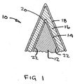
FIG. 1 is a sectional view of a cutting edge portion of a razor blade of the present invention. -
FIG. 2 is a front isometric view from above of a safety razor of the present invention. - Referring to now to the drawings, and in particular
Fig. 1 , the cutting edge portion of arazor blade 10 comprises asubstrate 12, a layer oftitanium containing material 14, a layer ofhard carbon material 16 and an outer layer of polytetrafluoroethylene (PTFE) 18. Thesubstrate 12 is typically made of stainless steel, although other substrates such as an amorphous alloy, a carbon steel or a ceramic material can be employed. A preferable stainless steel is disclosed inUS Patent Number 5,275,672 to Althaus et al and is most preferably the grade designated GIN 7 manufactured by HITACHI. One of skill in the art will understand that other stainless steel materials may be used. The substrate is typically supplied in an annealed state as an elongated flat strip, wound in a coil and is preferably 0,05mm to 0,1 mm thick, most preferably 0,1 mm, and is preferably 3mm wide but can be from 2mm to 23mm wide. The substrate may be perforated as is known in the art. The substrate is hardened, again as is known in the art to a hardness 900 on the Vickers scale (Hv). The substrate is sharpened to provide a cutting edge having a sharpenedtip 20 of radius less than 100 nm and preferably 20-50 nm. The sharpened tip hasadjacent facets 22 having an included angle less than 30 degrees and preferably 15-20 degrees measured 40 nm from the sharpened tip. The sharpening process includes grinding and honing stages and may include a further stropping stage. The sharpening process may be performed on both edges of the elongate substrate but is preferably on one edge only. As the elongate substrate exits the sharpening process it may be cut into individual razor blades and stacked one on the other, or preferably the elongate substrate is recoiled on to a carrier with the sharpened edge facing outward. The substrate is subsequently cleaned by any one of a number of processes known in the art to remove residues from the sharpening process and other contamination. Samples of the substrate are analyzed for cleanliness preferably by a photoelectron emission technique. Suitable measuring equipment is supplied by PET PHOTO EMISSION TECHNOLOGY and is designated SQM300. A substrate with an OSEE (optically stimulated electron emission) value at least 450 is adequately clean. - At least one carrier with recoiled substrate is loaded vertically (that is, with the axis of its coils horizontal) within a vacuum chamber. The vacuum chamber includes a target preferably comprising titanium, and two cathodic arc sources. The target may also comprise titanium alloyed with any carbide forming metal that comprises at least 51% titanium by atomic percent. Suitable process equipment including a vacuum chamber is manufactured by IONBOND. The vacuum chamber may alternately be constructed to have one or more stacks of razor blades loaded therein.
- The process steps performed within the vacuum chamber are as follows:
- In a first step, the vacuum chamber is sealed and evacuated to 0.3 mPa (20 microTorr) and a rate ofrise test performed to ensure the chamber has no vacuum leaks.
- The following glow discharge step removes minor contamination that might remain on the cutting edges. Oxygen is introduced into the chamber to a pressure of 2.00 to 5.99 (15 to 45 milliTorr). A bias voltage of -500 Volts is applied to the substrate and this is increased to - 1000 Volts and held for 2 minutes. In all process steps herein where a bias voltage is cited, this is preferably a pulsed square wave, pulsed from 0 Volts to the specified bias voltage at 25 kHz and a duty cycle of 62%. Other wave forms and frequencies may be employed. One of skill in the art will understand that the hard carbon material, infra, is a semi-conductor and requires a pulsed DC bias rather than a pure DC bias to avoid creating a static charge on the substrate. The oxygen supply is closed and argon is introduced into the chamber while the substrate is held at -1000 Volts. The vacuum chamber is then evacuated to 6.65 mPa (50 microTorr).
- The glow discharge step is followed by a magnetron sputtering step that cleans the surface of the target and subsequently deposits the titanium containing material on the cutting edges. A shutter is closed which masks the target. Argon is introduced into the chamber to a pressure of 0.266 to 2.66 Pa (2 to 20 milliTorr). The power on the target is set to a power density of 14 W/cm2 to 28 W/cm2. These conditions are held for 1-3 minutes as a pre-sputter step to clean the surface of the target. The shutter is then opened, exposing the target to the cutting edges so that the titanium containing material may be deposited on the cutting edges. A high bias voltage of -200 to -700 Volts, preferably -500 Volts, is applied to the substrate for about one minute. This high bias step is necessary to achieve adequate bonding of the titanium containing material to the sharpened tip of the cutting edge. The bias voltage is then reduced to a low bias setting of -20 to -60 volts for about 2 to 5 minutes. A minimum thickness of titanium containing material of 5 nm is deposited on the cutting edge.
- The magnetron sputtering step is followed by a preferred a-Diamond or amorphous diamond step that deposits a hard carbon material of amorphous diamond on the titanium containing material. The hard carbon material may also be Diamond-like Carbon (DLC). Two cathodic arc sources are preferably situated such that each carbon beam is approximately normal to one of each facet of the cutting edge. This is the optimum arrangement that will provide hardest coating. Suitable coatings however are achieved with a narrower angle of 60 degrees between the two carbon beams. Argon is introduced into the chamber to a pressure of 2.66 mPa to 1.197 Pa (20 microTorr to 9 milliTorr). The cathodic arc sources are set at 50 to 65 Amps with an initial bias voltage of -500 to -1000 Volts applied to the substrate. The initial phase of this a-Diamond step implants carbon in the titanium containing material layer to form a partial titanium carbide layer. This partial carbide layer is necessary to ensure adequate adhesion of the hard carbon material to the titanium containing material layer. This step is continued to deposit a
hard carbon layer 20 nm to 150 nm thick, with a preferred thickness of 20 to 80 nm. - The vacuum chamber is vented and the substrate removed. In a subsequent process, well known to one of skill in the art, an outer layer of polytetrafluoroethylene (PTFE) is deposited. A suitable PTFE is DRYFILM LW1200 manufactured by DUPONT, having a molecular weight of 40,000. The DRYFILM LW1200 is preferably diluted with alcohol as disclosed in
US Patent Application serial number 60/741,144 . One of skill in the art will understand other PTFE materials may be employed. - A
razor blade 10 is manufactured generally to the processes described herein. Individual razor blades may be in stack form or the coiled substrate may subsequently uncoiled and cut to a convenient length to form a single razor blade. - Referring now to
Fig. 2 , at least one razor blade is mounted in ahousing 100. The housing, with its razor blade or blades is selectively connected to ahandle 110 to provide asafety razor 120. The housing may contain one, two or three razor blades but preferably at least four. The housing may be permanently or removably connected to the handle. - In use, the cutting edge portion of the
razor blade 10 has improved resistance to failure by crack propagation compared to known cutting edges of razor blades having chromium coatings between their substrate and hard carbon coatings. The use of a titanium containing material on the cutting edge of a razor blade promotes adhesion of the hard carbon material. The razor blade has excellent shaving characteristics.
Claims (7)
- A method of making a razor blade (10), comprising:a substrate (12) with a cutting edge defined by a sharpened tip (20) and adjacent facets (22),a layer of titanium containing material (14) on the cutting edge,a layer of hard carbon material (16) on the titanium containing material layer (14), andan outer layer of polytetrafluoroethylene (18)wherein the layer of titanium containing material (14) is a partial titanium carbide layer, said method comprising:providing the substrate (12) with the cutting edge defined by the sharpened tip (20) and adjacent facets (22), adding the layer of titanium containing materials (14) to the cutting edge, adding the layer of hard carbon material (16) to the titanium containing material layer (14), and adding the outer layer of polytetrafluoroethylene (18), wherein the layer of titanium containing material (14) includes depositing the titanium containing material layer (14) by a physical vapor deposition process,wherein the physical vapor deposition process is a sputtering process,wherein the sputtering process is performed in a vacuum chamber that includes a target that comprises titanium,wherein the process steps carried out in said vacuum chamber comprise the following steps:i) a glow discharge step comprising introducing oxygen into the vacuum chamber to a pressure of 2.00 to 6.00 Pa (15 to 45 milliTorr),
applying a voltage of -500 V to the substrate (12), increasing the voltage to - 1000 V and holding it for 2 minutes,
closing the oxygen supply, introducing argon and then evacuating the vacuum chamber to 6.66 mPa (50 microTorr);ii) a magnetron sputtering process comprising introducing argon into the vacuum chamber to a pressure of 0.267 to 2.67 Pa (2 to 20 milliTorr),
applying a power density of about 14 W/cm2 to 28 W/cm2 to the target for a time of 1 to 3 minutes,
applying at least a high bias voltage of -200 to -700 V to the substrate (12) for one minute, and
applying a low bias voltage of -20 to -60 V to the substrate (12) for 2 to 5 minutes thereby depositing a minimum thickness of titanium containing material of 5 nm on the cutting edge;iii) an a-diamond step or diamond-like carbon (DLC) step,
introducing argon into the vacuum chamber to a pressure of 2.66 mPa to 1.20 Pa (20 microTorr to 9 milliTorr),
setting the cathodic arc sources at about 50 to 65 amps with an initial bias voltage of about -500 to -1000 V applied to the substrate (12) to form the partial titanium carbide layer (14);iv) continuing step iii) to deposit a hard carbon layer (16) 20 to 150 nm (200 to 1500 Angstroms) thick;wherein the sputtering process is performed in a first atmosphere comprising Argon having a pressure less than 6.65 Pa (50 milliTorr), wherein the titanium containing material layer (14) is implanted with carbon to form a partial titanium carbide layer, wherein the implanting is performed with a second bias voltage more positive than -1500 volts applied to the razor blade. - The method according to claim 1, wherein in step iii) two cathodic arc sources are situated such that each carbon beam is normal to one of each facet (22) of the cutting edge.
- The method according to claim 2, wherein the two cathodic arc sources are situated with an angle of 60 degrees between the two carbon beams.
- The method according to claim 1, wherein the hard carbon material is selected from the group consisting of diamond-like carbon and amorphous diamond.
- The method according to claim 1, wherein the polytetrafluoroethylene has a molecular weight of 40,000.
- The method according to claim 1, wherein the polytetrafluoroethylene layer (18) is on the layer of hard carbon material (16).
- The method of claim 4, wherein the layer of hard carbon material (16) has a thickness between 20 and 80 nm.
Applications Claiming Priority (2)
| Application Number | Priority Date | Filing Date | Title |
|---|---|---|---|
| US77237906P | 2006-02-10 | 2006-02-10 | |
| PCT/US2007/003571 WO2007095120A2 (en) | 2006-02-10 | 2007-02-09 | Multi-layer coating for razor blades |
Publications (2)
| Publication Number | Publication Date |
|---|---|
| EP1984152A2 EP1984152A2 (en) | 2008-10-29 |
| EP1984152B1 true EP1984152B1 (en) | 2013-04-10 |
Family
ID=38179612
Family Applications (1)
| Application Number | Title | Priority Date | Filing Date |
|---|---|---|---|
| EP07750410.8A Active EP1984152B1 (en) | 2006-02-10 | 2007-02-09 | Method for producing a multi-layer coating for razor blades |
Country Status (5)
| Country | Link |
|---|---|
| US (1) | US20070186424A1 (en) |
| EP (1) | EP1984152B1 (en) |
| JP (1) | JP2009525826A (en) |
| AU (1) | AU2007215243A1 (en) |
| WO (1) | WO2007095120A2 (en) |
Families Citing this family (17)
| Publication number | Priority date | Publication date | Assignee | Title |
|---|---|---|---|---|
| US8250764B2 (en) | 2007-04-16 | 2012-08-28 | Adco Industries-Technologies, L.P. | Adjustable utility knife |
| PL2276591T3 (en) | 2008-05-05 | 2013-11-29 | Eveready Battery Inc | Method of making a razor blade |
| CN102665936B (en) | 2009-10-22 | 2015-05-20 | 比克-维尔莱克 | Method for forming lubricating coating on razor blade, such blade and razor blade coating system |
| US20130014396A1 (en) | 2011-07-14 | 2013-01-17 | Kenneth James Skrobis | Razor blades having a wide facet angle |
| US20130014395A1 (en) * | 2011-07-14 | 2013-01-17 | Ashok Bakul Patel | Razor blades having a large tip radius |
| US8782909B1 (en) | 2013-02-12 | 2014-07-22 | ADCO Industries—Technologies, L.P. | Utility cutter |
| US11148309B2 (en) * | 2013-06-05 | 2021-10-19 | The Gillette Company Llc | Razor components with novel coating |
| MX388628B (en) | 2014-12-22 | 2025-03-20 | Bic Violex Sa | RAZOR BLADE. |
| US11654588B2 (en) * | 2016-08-15 | 2023-05-23 | The Gillette Company Llc | Razor blades |
| EP3639991A1 (en) | 2018-10-19 | 2020-04-22 | Edgewell Personal Care Brands, LLC | Razor blade and method of making it |
| WO2020176163A1 (en) | 2019-02-28 | 2020-09-03 | Edgewell Personal Care Brands, Llc | Razor blade and composition for a razor blade |
| DE102020003847A1 (en) * | 2020-06-26 | 2021-12-30 | KSB SE & Co. KGaA | Centrifugal pump for pumping media containing solids |
| CN111763945A (en) * | 2020-07-10 | 2020-10-13 | 北京市辐射中心 | Razor blade with multi-layer strengthening coating and preparation method thereof |
| CN116615318A (en) * | 2020-11-03 | 2023-08-18 | 吉列有限责任公司 | Razor blades with chromium boride-based coating |
| CA3229086A1 (en) * | 2021-08-24 | 2023-03-02 | Edgewell Personal Care Brands, Llc | System and method for coating a blade |
| US20250153381A1 (en) * | 2023-11-15 | 2025-05-15 | Dorco Co., Ltd. | Razor blade |
| CN122349464A (en) | 2023-12-11 | 2026-07-07 | Edgewell个人护理品牌有限责任公司 | Razor cartridge and blade for the same |
Family Cites Families (15)
| Publication number | Priority date | Publication date | Assignee | Title |
|---|---|---|---|---|
| US3682795A (en) * | 1969-07-28 | 1972-08-08 | Gillette Co | Sputter coating of razor blades with a beta-tungsten type alloy |
| GB8600829D0 (en) * | 1986-01-23 | 1986-02-19 | Gillette Co | Formation of hard coatings on cutting edges |
| NL8800345A (en) * | 1988-02-12 | 1989-09-01 | Philips Nv | CUTTING UNIT FOR A SHAVER AND SHAVER EQUIPPED WITH THIS CUTTING UNIT. |
| US5129289A (en) * | 1988-07-13 | 1992-07-14 | Warner-Lambert Company | Shaving razors |
| GB8821944D0 (en) * | 1988-09-19 | 1988-10-19 | Gillette Co | Method & apparatus for forming surface of workpiece |
| US5232568A (en) * | 1991-06-24 | 1993-08-03 | The Gillette Company | Razor technology |
| AU667816B2 (en) * | 1991-06-24 | 1996-04-18 | Gillette Company, The | Improvements in or relating to razor blades |
| US5669144A (en) * | 1991-11-15 | 1997-09-23 | The Gillette Company | Razor blade technology |
| US6330750B1 (en) * | 1996-01-11 | 2001-12-18 | Molecular Metallurgy, Inc. | Scapel blade having high sharpness and toughness |
| US5985459A (en) * | 1996-10-31 | 1999-11-16 | The Gillette Company | Method of treating razor blade cutting edges |
| JP4560964B2 (en) * | 2000-02-25 | 2010-10-13 | 住友電気工業株式会社 | Amorphous carbon coated member |
| US6684513B1 (en) * | 2000-02-29 | 2004-02-03 | The Gillette Company | Razor blade technology |
| JP4741056B2 (en) * | 2000-06-05 | 2011-08-03 | 株式会社貝印刃物開発センター | Blade member and method of manufacturing the blade edge |
| US7673541B2 (en) * | 2004-06-03 | 2010-03-09 | The Gillette Company | Colored razor blades |
| US20070124944A1 (en) * | 2005-11-30 | 2007-06-07 | Eveready Battery Company, Inc. | Razor blade and method of making it |
-
2007
- 2007-02-09 WO PCT/US2007/003571 patent/WO2007095120A2/en not_active Ceased
- 2007-02-09 US US11/704,541 patent/US20070186424A1/en not_active Abandoned
- 2007-02-09 EP EP07750410.8A patent/EP1984152B1/en active Active
- 2007-02-09 JP JP2008554394A patent/JP2009525826A/en active Pending
- 2007-02-09 AU AU2007215243A patent/AU2007215243A1/en not_active Abandoned
Also Published As
| Publication number | Publication date |
|---|---|
| WO2007095120A2 (en) | 2007-08-23 |
| JP2009525826A (en) | 2009-07-16 |
| US20070186424A1 (en) | 2007-08-16 |
| WO2007095120A3 (en) | 2007-10-25 |
| AU2007215243A1 (en) | 2007-08-23 |
| EP1984152A2 (en) | 2008-10-29 |
Similar Documents
| Publication | Publication Date | Title |
|---|---|---|
| US20070186424A1 (en) | Multi-layer coating for razor blades | |
| US9855665B2 (en) | Strengthened razor blade | |
| CN111032915B (en) | Wear-resistant PVD tool coating containing TiAlN nano-layer film | |
| JP4918656B2 (en) | Amorphous hard carbon film | |
| EP2171122B1 (en) | Thin film coating of blades | |
| CN102427918B (en) | Razor blade coating | |
| JPH06507100A (en) | Improvements regarding razor blades | |
| JP3722829B2 (en) | Improvements related to razor blades | |
| CN114846176B (en) | Coated cutting tool | |
| US5347887A (en) | Composite cutting edge | |
| JP2004238736A (en) | Hard film, and hard film-coated tool | |
| WO2016171627A1 (en) | A substantially transparent coating | |
| EP0579756B1 (en) | Coated cutting tool | |
| KR101101742B1 (en) | Thin film deposition method of razor blade | |
| CN104011256A (en) | Coated cutting tool | |
| JP3246513B2 (en) | Diamond-like carbon laminated film | |
| JP2001192206A (en) | Manufacturing method of amorphous carbon coated member | |
| JP2010202978A (en) | Amorphous carbon covered member | |
| WO2006079360A1 (en) | Razor blade, razor head, razor and method of manufacturing a razor blade | |
| KR800001297B1 (en) | Cutting tool with alloy coated sharpened edge | |
| CN121759882A (en) | Tough integrated low-stress ultra-thick AlTiN-based coating and preparation method and application thereof | |
| JPH01172558A (en) | Al member coated with wear-resistant layer | |
| TH14041A (en) | Improvements related to the razor blades of the shaver? | |
| HK1116291A (en) | Magnetic recording head and media comprising aluminum oxynitride underlayer and a diamond-like carbon overcoat | |
| TH19210B (en) | Improvements related to the razor blades of the shaver? |
Legal Events
| Date | Code | Title | Description |
|---|---|---|---|
| PUAI | Public reference made under article 153(3) epc to a published international application that has entered the european phase |
Free format text: ORIGINAL CODE: 0009012 |
|
| 17P | Request for examination filed |
Effective date: 20080812 |
|
| AK | Designated contracting states |
Kind code of ref document: A2 Designated state(s): AT BE BG CH CY CZ DE DK EE ES FI FR GB GR HU IE IS IT LI LT LU LV MC NL PL PT RO SE SI SK TR |
|
| 17Q | First examination report despatched |
Effective date: 20081118 |
|
| DAX | Request for extension of the european patent (deleted) | ||
| GRAP | Despatch of communication of intention to grant a patent |
Free format text: ORIGINAL CODE: EPIDOSNIGR1 |
|
| GRAS | Grant fee paid |
Free format text: ORIGINAL CODE: EPIDOSNIGR3 |
|
| GRAA | (expected) grant |
Free format text: ORIGINAL CODE: 0009210 |
|
| AK | Designated contracting states |
Kind code of ref document: B1 Designated state(s): AT BE BG CH CY CZ DE DK EE ES FI FR GB GR HU IE IS IT LI LT LU LV MC NL PL PT RO SE SI SK TR |
|
| REG | Reference to a national code |
Ref country code: GB Ref legal event code: FG4D |
|
| REG | Reference to a national code |
Ref country code: CH Ref legal event code: EP Ref country code: AT Ref legal event code: REF Ref document number: 605720 Country of ref document: AT Kind code of ref document: T Effective date: 20130415 |
|
| REG | Reference to a national code |
Ref country code: IE Ref legal event code: FG4D |
|
| REG | Reference to a national code |
Ref country code: DE Ref legal event code: R096 Ref document number: 602007029674 Country of ref document: DE Effective date: 20130606 |
|
| PG25 | Lapsed in a contracting state [announced via postgrant information from national office to epo] |
Ref country code: SI Free format text: LAPSE BECAUSE OF FAILURE TO SUBMIT A TRANSLATION OF THE DESCRIPTION OR TO PAY THE FEE WITHIN THE PRESCRIBED TIME-LIMIT Effective date: 20130410 |
|
| REG | Reference to a national code |
Ref country code: AT Ref legal event code: MK05 Ref document number: 605720 Country of ref document: AT Kind code of ref document: T Effective date: 20130410 |
|
| REG | Reference to a national code |
Ref country code: NL Ref legal event code: VDEP Effective date: 20130410 Ref country code: LT Ref legal event code: MG4D |
|
| PG25 | Lapsed in a contracting state [announced via postgrant information from national office to epo] |
Ref country code: AT Free format text: LAPSE BECAUSE OF FAILURE TO SUBMIT A TRANSLATION OF THE DESCRIPTION OR TO PAY THE FEE WITHIN THE PRESCRIBED TIME-LIMIT Effective date: 20130410 Ref country code: SE Free format text: LAPSE BECAUSE OF FAILURE TO SUBMIT A TRANSLATION OF THE DESCRIPTION OR TO PAY THE FEE WITHIN THE PRESCRIBED TIME-LIMIT Effective date: 20130410 Ref country code: NL Free format text: LAPSE BECAUSE OF FAILURE TO SUBMIT A TRANSLATION OF THE DESCRIPTION OR TO PAY THE FEE WITHIN THE PRESCRIBED TIME-LIMIT Effective date: 20130410 Ref country code: GR Free format text: LAPSE BECAUSE OF FAILURE TO SUBMIT A TRANSLATION OF THE DESCRIPTION OR TO PAY THE FEE WITHIN THE PRESCRIBED TIME-LIMIT Effective date: 20130711 Ref country code: LT Free format text: LAPSE BECAUSE OF FAILURE TO SUBMIT A TRANSLATION OF THE DESCRIPTION OR TO PAY THE FEE WITHIN THE PRESCRIBED TIME-LIMIT Effective date: 20130410 Ref country code: FI Free format text: LAPSE BECAUSE OF FAILURE TO SUBMIT A TRANSLATION OF THE DESCRIPTION OR TO PAY THE FEE WITHIN THE PRESCRIBED TIME-LIMIT Effective date: 20130410 Ref country code: BE Free format text: LAPSE BECAUSE OF FAILURE TO SUBMIT A TRANSLATION OF THE DESCRIPTION OR TO PAY THE FEE WITHIN THE PRESCRIBED TIME-LIMIT Effective date: 20130410 Ref country code: IS Free format text: LAPSE BECAUSE OF FAILURE TO SUBMIT A TRANSLATION OF THE DESCRIPTION OR TO PAY THE FEE WITHIN THE PRESCRIBED TIME-LIMIT Effective date: 20130810 Ref country code: ES Free format text: LAPSE BECAUSE OF FAILURE TO SUBMIT A TRANSLATION OF THE DESCRIPTION OR TO PAY THE FEE WITHIN THE PRESCRIBED TIME-LIMIT Effective date: 20130721 Ref country code: PT Free format text: LAPSE BECAUSE OF FAILURE TO SUBMIT A TRANSLATION OF THE DESCRIPTION OR TO PAY THE FEE WITHIN THE PRESCRIBED TIME-LIMIT Effective date: 20130812 |
|
| PG25 | Lapsed in a contracting state [announced via postgrant information from national office to epo] |
Ref country code: BG Free format text: LAPSE BECAUSE OF FAILURE TO SUBMIT A TRANSLATION OF THE DESCRIPTION OR TO PAY THE FEE WITHIN THE PRESCRIBED TIME-LIMIT Effective date: 20130710 Ref country code: LV Free format text: LAPSE BECAUSE OF FAILURE TO SUBMIT A TRANSLATION OF THE DESCRIPTION OR TO PAY THE FEE WITHIN THE PRESCRIBED TIME-LIMIT Effective date: 20130410 Ref country code: CY Free format text: LAPSE BECAUSE OF FAILURE TO SUBMIT A TRANSLATION OF THE DESCRIPTION OR TO PAY THE FEE WITHIN THE PRESCRIBED TIME-LIMIT Effective date: 20130410 Ref country code: PL Free format text: LAPSE BECAUSE OF FAILURE TO SUBMIT A TRANSLATION OF THE DESCRIPTION OR TO PAY THE FEE WITHIN THE PRESCRIBED TIME-LIMIT Effective date: 20130410 |
|
| PG25 | Lapsed in a contracting state [announced via postgrant information from national office to epo] |
Ref country code: DK Free format text: LAPSE BECAUSE OF FAILURE TO SUBMIT A TRANSLATION OF THE DESCRIPTION OR TO PAY THE FEE WITHIN THE PRESCRIBED TIME-LIMIT Effective date: 20130410 Ref country code: EE Free format text: LAPSE BECAUSE OF FAILURE TO SUBMIT A TRANSLATION OF THE DESCRIPTION OR TO PAY THE FEE WITHIN THE PRESCRIBED TIME-LIMIT Effective date: 20130410 Ref country code: SK Free format text: LAPSE BECAUSE OF FAILURE TO SUBMIT A TRANSLATION OF THE DESCRIPTION OR TO PAY THE FEE WITHIN THE PRESCRIBED TIME-LIMIT Effective date: 20130410 Ref country code: CZ Free format text: LAPSE BECAUSE OF FAILURE TO SUBMIT A TRANSLATION OF THE DESCRIPTION OR TO PAY THE FEE WITHIN THE PRESCRIBED TIME-LIMIT Effective date: 20130410 |
|
| PLBE | No opposition filed within time limit |
Free format text: ORIGINAL CODE: 0009261 |
|
| STAA | Information on the status of an ep patent application or granted ep patent |
Free format text: STATUS: NO OPPOSITION FILED WITHIN TIME LIMIT |
|
| PG25 | Lapsed in a contracting state [announced via postgrant information from national office to epo] |
Ref country code: IT Free format text: LAPSE BECAUSE OF FAILURE TO SUBMIT A TRANSLATION OF THE DESCRIPTION OR TO PAY THE FEE WITHIN THE PRESCRIBED TIME-LIMIT Effective date: 20130410 Ref country code: RO Free format text: LAPSE BECAUSE OF FAILURE TO SUBMIT A TRANSLATION OF THE DESCRIPTION OR TO PAY THE FEE WITHIN THE PRESCRIBED TIME-LIMIT Effective date: 20130410 |
|
| 26N | No opposition filed |
Effective date: 20140113 |
|
| REG | Reference to a national code |
Ref country code: DE Ref legal event code: R097 Ref document number: 602007029674 Country of ref document: DE Effective date: 20140113 |
|
| PG25 | Lapsed in a contracting state [announced via postgrant information from national office to epo] |
Ref country code: LU Free format text: LAPSE BECAUSE OF FAILURE TO SUBMIT A TRANSLATION OF THE DESCRIPTION OR TO PAY THE FEE WITHIN THE PRESCRIBED TIME-LIMIT Effective date: 20140209 Ref country code: MC Free format text: LAPSE BECAUSE OF FAILURE TO SUBMIT A TRANSLATION OF THE DESCRIPTION OR TO PAY THE FEE WITHIN THE PRESCRIBED TIME-LIMIT Effective date: 20130410 |
|
| REG | Reference to a national code |
Ref country code: CH Ref legal event code: PL |
|
| PG25 | Lapsed in a contracting state [announced via postgrant information from national office to epo] |
Ref country code: CH Free format text: LAPSE BECAUSE OF NON-PAYMENT OF DUE FEES Effective date: 20140228 Ref country code: LI Free format text: LAPSE BECAUSE OF NON-PAYMENT OF DUE FEES Effective date: 20140228 |
|
| REG | Reference to a national code |
Ref country code: IE Ref legal event code: MM4A |
|
| PG25 | Lapsed in a contracting state [announced via postgrant information from national office to epo] |
Ref country code: IE Free format text: LAPSE BECAUSE OF NON-PAYMENT OF DUE FEES Effective date: 20140209 |
|
| REG | Reference to a national code |
Ref country code: FR Ref legal event code: PLFP Year of fee payment: 10 |
|
| PG25 | Lapsed in a contracting state [announced via postgrant information from national office to epo] |
Ref country code: HU Free format text: LAPSE BECAUSE OF FAILURE TO SUBMIT A TRANSLATION OF THE DESCRIPTION OR TO PAY THE FEE WITHIN THE PRESCRIBED TIME-LIMIT; INVALID AB INITIO Effective date: 20070209 Ref country code: TR Free format text: LAPSE BECAUSE OF FAILURE TO SUBMIT A TRANSLATION OF THE DESCRIPTION OR TO PAY THE FEE WITHIN THE PRESCRIBED TIME-LIMIT Effective date: 20130410 |
|
| REG | Reference to a national code |
Ref country code: FR Ref legal event code: PLFP Year of fee payment: 11 |
|
| PGFP | Annual fee paid to national office [announced via postgrant information from national office to epo] |
Ref country code: FR Payment date: 20170223 Year of fee payment: 11 |
|
| PGFP | Annual fee paid to national office [announced via postgrant information from national office to epo] |
Ref country code: GB Payment date: 20170227 Year of fee payment: 11 |
|
| GBPC | Gb: european patent ceased through non-payment of renewal fee |
Effective date: 20180209 |
|
| REG | Reference to a national code |
Ref country code: FR Ref legal event code: ST Effective date: 20181031 |
|
| PG25 | Lapsed in a contracting state [announced via postgrant information from national office to epo] |
Ref country code: FR Free format text: LAPSE BECAUSE OF NON-PAYMENT OF DUE FEES Effective date: 20180228 Ref country code: GB Free format text: LAPSE BECAUSE OF NON-PAYMENT OF DUE FEES Effective date: 20180209 |
|
| P01 | Opt-out of the competence of the unified patent court (upc) registered |
Effective date: 20230526 |
|
| P02 | Opt-out of the competence of the unified patent court (upc) changed |
Effective date: 20230703 |
|
| PGFP | Annual fee paid to national office [announced via postgrant information from national office to epo] |
Ref country code: DE Payment date: 20260227 Year of fee payment: 20 |