EP1287953A1 - Cutting blade and method of producing the same - Google Patents
Cutting blade and method of producing the same Download PDFInfo
- Publication number
- EP1287953A1 EP1287953A1 EP01934522A EP01934522A EP1287953A1 EP 1287953 A1 EP1287953 A1 EP 1287953A1 EP 01934522 A EP01934522 A EP 01934522A EP 01934522 A EP01934522 A EP 01934522A EP 1287953 A1 EP1287953 A1 EP 1287953A1
- Authority
- EP
- European Patent Office
- Prior art keywords
- base plate
- blade
- coating layer
- layer
- edge
- Prior art date
- Legal status (The legal status is an assumption and is not a legal conclusion. Google has not performed a legal analysis and makes no representation as to the accuracy of the status listed.)
- Granted
Links
Images


Classifications
-
- B—PERFORMING OPERATIONS; TRANSPORTING
- B26—HAND CUTTING TOOLS; CUTTING; SEVERING
- B26B—HAND-HELD CUTTING TOOLS NOT OTHERWISE PROVIDED FOR
- B26B21/00—Razors of the open or knife type; Safety razors or other shaving implements of the planing type; Hair-trimming devices involving a razor-blade; Equipment therefor
- B26B21/54—Razor-blades
- B26B21/58—Razor-blades characterised by the material
- B26B21/60—Razor-blades characterised by the material by the coating material
-
- B—PERFORMING OPERATIONS; TRANSPORTING
- B26—HAND CUTTING TOOLS; CUTTING; SEVERING
- B26B—HAND-HELD CUTTING TOOLS NOT OTHERWISE PROVIDED FOR
- B26B21/00—Razors of the open or knife type; Safety razors or other shaving implements of the planing type; Hair-trimming devices involving a razor-blade; Equipment therefor
- B26B21/54—Razor-blades
- B26B21/56—Razor-blades characterised by the shape
-
- Y—GENERAL TAGGING OF NEW TECHNOLOGICAL DEVELOPMENTS; GENERAL TAGGING OF CROSS-SECTIONAL TECHNOLOGIES SPANNING OVER SEVERAL SECTIONS OF THE IPC; TECHNICAL SUBJECTS COVERED BY FORMER USPC CROSS-REFERENCE ART COLLECTIONS [XRACs] AND DIGESTS
- Y10—TECHNICAL SUBJECTS COVERED BY FORMER USPC
- Y10S—TECHNICAL SUBJECTS COVERED BY FORMER USPC CROSS-REFERENCE ART COLLECTIONS [XRACs] AND DIGESTS
- Y10S428/00—Stock material or miscellaneous articles
- Y10S428/922—Static electricity metal bleed-off metallic stock
- Y10S428/9335—Product by special process
- Y10S428/938—Vapor deposition or gas diffusion
-
- Y—GENERAL TAGGING OF NEW TECHNOLOGICAL DEVELOPMENTS; GENERAL TAGGING OF CROSS-SECTIONAL TECHNOLOGIES SPANNING OVER SEVERAL SECTIONS OF THE IPC; TECHNICAL SUBJECTS COVERED BY FORMER USPC CROSS-REFERENCE ART COLLECTIONS [XRACs] AND DIGESTS
- Y10—TECHNICAL SUBJECTS COVERED BY FORMER USPC
- Y10S—TECHNICAL SUBJECTS COVERED BY FORMER USPC CROSS-REFERENCE ART COLLECTIONS [XRACs] AND DIGESTS
- Y10S76/00—Metal tools and implements, making
- Y10S76/08—Razor blade manufacturing
-
- Y—GENERAL TAGGING OF NEW TECHNOLOGICAL DEVELOPMENTS; GENERAL TAGGING OF CROSS-SECTIONAL TECHNOLOGIES SPANNING OVER SEVERAL SECTIONS OF THE IPC; TECHNICAL SUBJECTS COVERED BY FORMER USPC CROSS-REFERENCE ART COLLECTIONS [XRACs] AND DIGESTS
- Y10—TECHNICAL SUBJECTS COVERED BY FORMER USPC
- Y10T—TECHNICAL SUBJECTS COVERED BY FORMER US CLASSIFICATION
- Y10T428/00—Stock material or miscellaneous articles
- Y10T428/12—All metal or with adjacent metals
- Y10T428/12229—Intermediate article [e.g., blank, etc.]
- Y10T428/12271—Intermediate article [e.g., blank, etc.] having discrete fastener, marginal fastening, taper, or end structure
-
- Y—GENERAL TAGGING OF NEW TECHNOLOGICAL DEVELOPMENTS; GENERAL TAGGING OF CROSS-SECTIONAL TECHNOLOGIES SPANNING OVER SEVERAL SECTIONS OF THE IPC; TECHNICAL SUBJECTS COVERED BY FORMER USPC CROSS-REFERENCE ART COLLECTIONS [XRACs] AND DIGESTS
- Y10—TECHNICAL SUBJECTS COVERED BY FORMER USPC
- Y10T—TECHNICAL SUBJECTS COVERED BY FORMER US CLASSIFICATION
- Y10T428/00—Stock material or miscellaneous articles
- Y10T428/12—All metal or with adjacent metals
- Y10T428/12299—Workpiece mimicking finished stock having nonrectangular or noncircular cross section
-
- Y—GENERAL TAGGING OF NEW TECHNOLOGICAL DEVELOPMENTS; GENERAL TAGGING OF CROSS-SECTIONAL TECHNOLOGIES SPANNING OVER SEVERAL SECTIONS OF THE IPC; TECHNICAL SUBJECTS COVERED BY FORMER USPC CROSS-REFERENCE ART COLLECTIONS [XRACs] AND DIGESTS
- Y10—TECHNICAL SUBJECTS COVERED BY FORMER USPC
- Y10T—TECHNICAL SUBJECTS COVERED BY FORMER US CLASSIFICATION
- Y10T428/00—Stock material or miscellaneous articles
- Y10T428/12—All metal or with adjacent metals
- Y10T428/12458—All metal or with adjacent metals having composition, density, or hardness gradient
-
- Y—GENERAL TAGGING OF NEW TECHNOLOGICAL DEVELOPMENTS; GENERAL TAGGING OF CROSS-SECTIONAL TECHNOLOGIES SPANNING OVER SEVERAL SECTIONS OF THE IPC; TECHNICAL SUBJECTS COVERED BY FORMER USPC CROSS-REFERENCE ART COLLECTIONS [XRACs] AND DIGESTS
- Y10—TECHNICAL SUBJECTS COVERED BY FORMER USPC
- Y10T—TECHNICAL SUBJECTS COVERED BY FORMER US CLASSIFICATION
- Y10T428/00—Stock material or miscellaneous articles
- Y10T428/12—All metal or with adjacent metals
- Y10T428/12493—Composite; i.e., plural, adjacent, spatially distinct metal components [e.g., layers, joint, etc.]
- Y10T428/12535—Composite; i.e., plural, adjacent, spatially distinct metal components [e.g., layers, joint, etc.] with additional, spatially distinct nonmetal component
- Y10T428/12625—Free carbon containing component
-
- Y—GENERAL TAGGING OF NEW TECHNOLOGICAL DEVELOPMENTS; GENERAL TAGGING OF CROSS-SECTIONAL TECHNOLOGIES SPANNING OVER SEVERAL SECTIONS OF THE IPC; TECHNICAL SUBJECTS COVERED BY FORMER USPC CROSS-REFERENCE ART COLLECTIONS [XRACs] AND DIGESTS
- Y10—TECHNICAL SUBJECTS COVERED BY FORMER USPC
- Y10T—TECHNICAL SUBJECTS COVERED BY FORMER US CLASSIFICATION
- Y10T428/00—Stock material or miscellaneous articles
- Y10T428/12—All metal or with adjacent metals
- Y10T428/12493—Composite; i.e., plural, adjacent, spatially distinct metal components [e.g., layers, joint, etc.]
- Y10T428/12674—Ge- or Si-base component
-
- Y—GENERAL TAGGING OF NEW TECHNOLOGICAL DEVELOPMENTS; GENERAL TAGGING OF CROSS-SECTIONAL TECHNOLOGIES SPANNING OVER SEVERAL SECTIONS OF THE IPC; TECHNICAL SUBJECTS COVERED BY FORMER USPC CROSS-REFERENCE ART COLLECTIONS [XRACs] AND DIGESTS
- Y10—TECHNICAL SUBJECTS COVERED BY FORMER USPC
- Y10T—TECHNICAL SUBJECTS COVERED BY FORMER US CLASSIFICATION
- Y10T428/00—Stock material or miscellaneous articles
- Y10T428/12—All metal or with adjacent metals
- Y10T428/12493—Composite; i.e., plural, adjacent, spatially distinct metal components [e.g., layers, joint, etc.]
- Y10T428/12729—Group IIA metal-base component
-
- Y—GENERAL TAGGING OF NEW TECHNOLOGICAL DEVELOPMENTS; GENERAL TAGGING OF CROSS-SECTIONAL TECHNOLOGIES SPANNING OVER SEVERAL SECTIONS OF THE IPC; TECHNICAL SUBJECTS COVERED BY FORMER USPC CROSS-REFERENCE ART COLLECTIONS [XRACs] AND DIGESTS
- Y10—TECHNICAL SUBJECTS COVERED BY FORMER USPC
- Y10T—TECHNICAL SUBJECTS COVERED BY FORMER US CLASSIFICATION
- Y10T428/00—Stock material or miscellaneous articles
- Y10T428/12—All metal or with adjacent metals
- Y10T428/12493—Composite; i.e., plural, adjacent, spatially distinct metal components [e.g., layers, joint, etc.]
- Y10T428/12736—Al-base component
-
- Y—GENERAL TAGGING OF NEW TECHNOLOGICAL DEVELOPMENTS; GENERAL TAGGING OF CROSS-SECTIONAL TECHNOLOGIES SPANNING OVER SEVERAL SECTIONS OF THE IPC; TECHNICAL SUBJECTS COVERED BY FORMER USPC CROSS-REFERENCE ART COLLECTIONS [XRACs] AND DIGESTS
- Y10—TECHNICAL SUBJECTS COVERED BY FORMER USPC
- Y10T—TECHNICAL SUBJECTS COVERED BY FORMER US CLASSIFICATION
- Y10T428/00—Stock material or miscellaneous articles
- Y10T428/12—All metal or with adjacent metals
- Y10T428/12493—Composite; i.e., plural, adjacent, spatially distinct metal components [e.g., layers, joint, etc.]
- Y10T428/12771—Transition metal-base component
- Y10T428/12778—Alternative base metals from diverse categories
-
- Y—GENERAL TAGGING OF NEW TECHNOLOGICAL DEVELOPMENTS; GENERAL TAGGING OF CROSS-SECTIONAL TECHNOLOGIES SPANNING OVER SEVERAL SECTIONS OF THE IPC; TECHNICAL SUBJECTS COVERED BY FORMER USPC CROSS-REFERENCE ART COLLECTIONS [XRACs] AND DIGESTS
- Y10—TECHNICAL SUBJECTS COVERED BY FORMER USPC
- Y10T—TECHNICAL SUBJECTS COVERED BY FORMER US CLASSIFICATION
- Y10T83/00—Cutting
- Y10T83/929—Tool or tool with support
- Y10T83/9319—Toothed blade or tooth therefor
Definitions
- the present invention relates to a blade, and more particularly, to a blade having a coating layer on its edge and a method for manufacturing such blade.
- a blade such as a razor or microtome
- a process in which the surface of a blade is coated by a 100% chrome film there is a process in which the surface of a blade is coated by a 100% chrome film.
- a first perspective of the present invention provides a blade including a base plate having an edge and a mixture layer formed by coating layer for coating at least the edge of the base plate.
- the coating layer includes at least one metal, which is selected from a group consisting of Pt, Zr, W, Ti, Ag, Cu, Co, Fe, Ge, Al, Mg, Zn, and Cr, and a carbon material.
- a second perspective of the present invention provides a blade including a base plate having an edge and a coating layer for coating at least the edge.
- the coating layer includes an intermediate layer which main component is at least one metal selected from a group consisting of Pt, Zr, W, Ti, Ag, Cu, Co, Fe, Ge, Al, Mg, Zn, and Cr, and a carbon layer formed on the intermediate layer.
- a third perspective of the present invention provides a blade including a base plate having an edge and a coating layer for coating at least the edge.
- the coating layer includes an intermediate layer which main component is at least one metal, which is selected from a group consisting of Pt, Zr, W, Ti, Ag, Cu, Co, Fe, Ge, Al, Mg, Zn, and Cr, and a mixture layer formed on the intermediate layer and including at least one metal, which is selected from a group consisting of Pt, Zr, W, Ti, Ag, Cu, Co, Fe, Ge, Al, Mg, Zn, and Cr, and a carbon material.
- a fourth perspective of the present invention provides a blade including a base plate having an edge, which is formed to become narrowed toward a tip of the edge, and a coating layer for coating at least the edge.
- the coating layer is formed by partially removing the coating layer at the tip side of the edge and has at least one tapered surface, which is tapered toward the tip of the edge.
- a fifth perspective of the present invention provides a blade including an edge defined by two surfaces.
- the edge includes a tapered surface formed by partially removing at least one of the two surfaces.
- a sixth perspective of the present invention provides a blade including a base plate having an edge defined by two surfaces and a coating layer for coating the base plate.
- the base plate includes two first inner tapered surfaces, which extend along the two surfaces from an end of the base plate, and two second inner tapered surfaces, which extend continuously from the two first inner tapered surfaces, respectively. An angle between the two first inner tapered surfaces is greater than an angle between the two second inner tapered surfaces.
- the coating layer includes two first outer tapered surfaces, connected to each other at a tip of the edge, and two second outer tapered surfaces, which extend continuously from the two first outer tapered surfaces, respectively. An angle between the two first outer tapered surfaces is greater than an angle between the two second outer tapered surfaces.
- a seventh perspective of the present invention provides a method for manufacturing a blade including the steps of preparing a base plate having two surfaces, forming the two surfaces of the base plate so that the space between the two surfaces is narrowed as an end of the base plate becomes closer, forming a coating layer for coating at least the end of the base plate, and forming at least one tapered surface, which is tapered from a position corresponding to the edge of the coating layer, by partially removing the coating layer.
- An eighth perspective of the present invention provides a method for manufacturing a blade including the steps of preparing a base plate having two surfaces and an end defined by the two surfaces, forming a coating layer for coating at least the end of the base plate, forming a tapered surface by removing at least one of two surfaces of the coating layer corresponding to the two surfaces of the base plate, and forming a second coating layer on the coating layer.
- a ninth perspective of the present invention provides a method for manufacturing a blade including the steps of preparing a base plate having two surfaces, forming the two surfaces of the base plate so that the space between the two surfaces become narrowed as an end of the base plate becomes closer, and forming a tapered surface by removing at least one of the two surfaces of the base plate.
- a tenth perspective of the present invention provides a method for manufacturing a blade including the steps of, preparing a base plate having two surfaces, forming the two surfaces of the base plate so that the space between the two surfaces become narrowed as an end of the base plate becomes closer, forming a tapered surface by removing at least one of the two surfaces of the base plate, and forming a coating layer for coating the tapered surface.
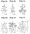
- the blade 1 is manufactured from a base plate 3 through the following steps.
- the base plate 3 is ground to form tapered side surfaces 4, 5. More specifically, the tapered side surfaces 4, 5 are formed so that the base plate 3 narrows at positions closer to the distal end and so that the angles of the tapered side surfaces 4, 5 relative to a middle plane 3a is the same, as shown in Fig. 1(a).
- Preferred materials of the base plate 3 are carbon steel, stainless steel, aluminum alloy, fine ceramics, such as zirconium or alumina, and hard metal, such as tungsten carbide (WC).
- both surfaces 4 and 5 are ground and finished, as shown in Fig. 1(b).
- the grinding may be omitted.
- a blade finishing process is performed, as described below.
- first surfaces 4a, 5a are formed at positions near the upper end of the base plate 3 to sharpen the upper end of the base plate 3.
- Second surfaces 4b, 5b, which are respectively continuous to the first surfaces 4a, 5a, are part of the surfaces 4, 5 prior to the removal. It is preferred that the first surfaces 4a, 5a define an edge forming angle ⁇ a that is greater than an edge forming angle ⁇ b defined by the second surfaces 4b, 5b.
- the first surfaces 4a, 5a may be flush with the second surfaces 4b, 5b. In this case, the two angles of ⁇ a, ⁇ b are equal to each other.
- the edge forming angle ⁇ s defined by the two first surfaces 4a, 5a may be smaller than the edge forming angle ⁇ b defined by the two second surfaces 4b, 5b.
- the third step be performed by carrying out dry etching, such as sputter etching. It is preferred that the removal dimension L1 of the upper end portion of the base plate 3 be between 10 to 200nm. It is preferred that the edge forming angle ⁇ b be between 17 to 25 degrees and that the edge forming angle ⁇ a be between 17 to 30 degrees.
- the base plate 3 is coated by the coating layer 6, as shown in Fig. 1(d).
- the coating layer 6 includes a left side surface 7 and a right side surface 8, which are formed substantially along the surfaces 4, 5 of the base plate 3.
- first surfaces 7a, 8a are formed at positions near the upper end of the coating layer 6 to sharpen the upper end of the coating layer 6.
- Second surfaces 7b, 8b, which are respectively continuous to the first surfaces 7a, 8a, are part of the surfaces 7, 8 prior to the removal. It is preferred that the first surfaces 7a, 8a define an edge forming angle ⁇ a that is greater than an edge forming angle ⁇ b defined by the second surfaces 7b, 8b.
- the first surfaces 7a, 8a may be flush with the second surfaces 7b, 8b. In this case, the two angles ⁇ a, ⁇ b are equal to each other.
- the edge forming angle ⁇ a of the two first surfaces 7a, 8a may be smaller than the edge forming angle ⁇ b of the two second surfaces 7b, 8b. It is preferred that the fifth step be performed by carrying out dry etching, such as sputter etching. It is preferred that the removal dimension L2 of the upper end portion of the coating layer 6 be between 5 to 150nm. It is preferred that the edge forming angle ⁇ b be between 17 to 30 degrees and that the edge angle ⁇ a be between 17 to 45 degrees.
- a fluororesin layer 9 is formed on the coating layer 6, as shown in Fig. 1(f).
- the fluororesin layer 9 improves the sliding smoothness of the blade 1 during usage.
- the material of fluororesin layer 9 is, for example, polytetrafluoroethylene (PTFE).
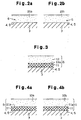
- Figs. 2(a), 2(b), 3, 4(a), 4(b), 5(a), 5(b), 5(c), and 5(d) each show an enlarged cross-sectional view of a preferred coating layer 6.
- the coating layer 6 of each drawing will now be described.
- the materials of the coating layers 6 in Figs. 2(a) and 2(b) include at least one metal selected from a group consisting of platinum (Pt), zirconium (Zr), tungsten (W), titanium (Ti), silver (Ag), copper (Cu), cobalt (Co), iron (Fe), germanium (Ge), aluminum (Al), magnesium (Mg), zinc (Zn), and chromium (Cr), and a hard carbon material, such as diamond-like carbon (DLC).
- the coating layer 6 shown in Fig. 2(a) is a mixture layer 10a, in which the above selected metal is uniformly mixed in DLC.
- the coating layer 6 shown in Fig. 2(b) is a mixture layer 10b, in which a ratio of the selected metal (concentration) changes at positions closer to the surfaces 4, 5 of the base plate 3.
- concentration of the selected metal in the mixture layer 10b increases or decreases as the base plate 3 becomes closer.
- concentration of the selected metal increase as the base plate 3 becomes closer to increase the adherence of the mixture layer 10b (the coating layer 6) and the base plate 3. This prevents the mixture layer 10b (the coating layer 6) from exfoliating from the base plate 3.
- the coating layer 6 shown in Fig. 3 includes an intermediate layer 11, which coats the surfaces 4, 5 of the base plate 3, and a hard carbon layer (DLC layer) 12, which coats the surface 11a of the intermediate layer 11.
- the main component of the intermediate layer 11 is at least one metal selected from a group consisting of Pt, Zr, W, Ti, Ag, Cu, Co, Fe, Ge, Al, Mg, Zn, and Cr.
- the coating layers 6 shown in Fig. 4(a) and 4(b) include an intermediate layer 11, which coats the surfaces 4, 5 of the base plate 3, and mixture layers 10a, 10b, which coat a surface 11a of the intermediate layer 11.
- the main component of the intermediate layer 11 is at least one metal selected from a group consisting of Pt, Zr, W, Ti, Ag, Cu, Co, Fe, Ge, Al, Mg, Zn, and Cr.
- the mixture layers 10a, 10b are each mixtures of at least one metal selected from a group consisting of Pt, Zr, W, Ti, Ag, Cu, Co, Fe, Ge, Al, Mg, Zn, and Cr and a hard carbon material, such as DLC.
- a hard carbon material such as DLC.
- the selected metal is uniformly mixed in the DLC.
- the ratio of the selected metal defines a gradient as the surface 11a of the intermediate layer 11 (the surfaces 4 and 5 of the base plate 3) becomes closer.
- the concentration of the selected metal increases or decreases as the intermediate layer 11 becomes closer. It is preferred that, for example, the concentration of the selected metal increase as intermediate layer 11 becomes closer. In this case, the adhesion of the mixture layer 10b and the intermediate layer 11 increases. This prevents the mixture layer 10b from exfoliating from the intermediate layer 11.
- the coating layer 6 shown in Fig. 5(a) includes a DLC layer 12, which coats the mixture layer 10a of Fig. 4(a).
- the coating layer 6 shown in Fig. 5(b) includes a DLC layer 12, which coats the mixture layer 10b of Fig. 4(b). It is preferred that the concentration of the selected metal in the mixture layer 10b of Fig. 5(b) increase as the intermediate layer 11 becomes closer. In this case, the adhesion of the mixture layer 10b and the intermediate layer 11 increases to prevent the mixture layer 10b from exfoliating from the intermediate layer 11. Since the concentration of carbon in the mixture layer 10b becomes higher as the DLC layer 12 becomes closer, the adhesion of the DLC layer 12 and the mixture layer 10b increases and prevents the DLC layer 12 from exfoliating from the mixture layer 10b. As a result, the sharpness and durability of the blade 1 increase.
- the coating layer 6 shown in Fig. 5(c) includes a plurality of (e.g., three) mixture layers 13a, 13b, 13c in lieu of the single mixture layer 10a of Fig. 5(a).
- the mixture layers 13a, 13b, and 13c each have a uniform metal composition.
- the compositions of mixture layers 13a, 13b, and 13c of Fig. 5(c) differ from one another.
- the coating layer 6 shown in Fig. 5(d) includes a plurality of (e.g., three) mixture layers 13a, 13b, and 13c in lieu of a single mixture layer 10b shown in Fig. 5(b).
- the mixture layers 13a, 13b, and 13c of Fig. 5(d) each have metal with concentration gradient.
- the mixture layers 13a, 13b, and 13c of Figs. 5(c) and 5(d) each include a metal or a composition of the metal selected as required from the above metal group. It is preferred that the composition be selected as required from, for example, *N (nitride), *CN (carbon nitride), and *C (carbide). Symbol * represents at least one metal of the metal group.
- a plurality of the mixture layers 10a, 10b of Figs. 2(a), 2(b), 4(a), 4(b), 5(a), and 5(b), the mixture layers 13a, 13b, and 13c of Figs. 5(c) and 5(d), and the intermediate layers 11 of Figs. 3, 4(a), 4(b) and Figs. 5(a) to 5(d) may be superimposed.
- a coating layer 6 entirely or partially coats the edge 2. Further, the edge 2 may be coated by multiple types of coating layers 6.
- a coating layer 6 is formed through processes including sputtering, such as high frequency sputter, high speed low temperature sputter (magnetron sputter), and reactive sputter, any type of vapor deposition, any type of ion plating, and any type of vapor phase growth (CVD).
- sputtering such as high frequency sputter, high speed low temperature sputter (magnetron sputter), and reactive sputter, any type of vapor deposition, any type of ion plating, and any type of vapor phase growth (CVD).
- Hard carbon includes, for example, diamond.
- C 3 N 4 may be used as the mixture layers 10a, 10b, 13a, 13b, 13c and the DLC layer 12.
- C 3 N 4 includes crystallinity and mechanical characteristics similar to diamond and is theoretically harder than the diamond.
- a layer of C 3 N 4 is formed by methods such as ionization magnetron sputtering, arc plasma jet CVD, pulsed laser deposition, or reactive ionized cluster beam.
- a first step shown in Fig. 1(a) is a blade forming process, in which a stainless steel base plate 3 is ground with a rough grindstone. An edge forming angle ⁇ b defined by surfaces 4 and 5 is between 17 to 25 degrees.
- the surfaces 4, 5 are ground with a razor strap.
- an upper end portion of the base plate 3 is removed by carrying out sputter etching such that an edge forming angle ⁇ a of the first surfaces 4a and 5a becomes greater than an edge forming angle ⁇ b of the second surfaces 4b and 5b.
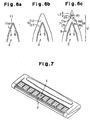
- the intermediate layer 11 which coats the base plate 3, is formed by carrying out sputtering.
- the thickness of the intermediate layer is 5 to 100nm and preferably 5 to 50% of the thickness of the final coating layer 6.
- the thickness of the intermediate layer 11 is about 25nm, which is about 25% of the thickness of the final coating layer 6.
- the DLC layer 12 which coats the surface 11a of the intermediate layer 11, is formed by carrying out sputtering. It is preferred that the thickness of the DLC layer 12 be 10 to 200nm. The thickness is about 75nm in the present example.
- an upper end of the DLC layer 12 is removed by carrying out sputter etching to form a sharp upper end portion in the DLC layer 12.
- the removal dimension L2 of the upper portion is preferably between 5 to 150nm, and more preferably between 50 to 100nm.
- the edge forming angle ⁇ a of the first surfaces 7a and 8a is between 17 to 45 degrees after the removal while an edge forming angle ⁇ b is between 17 to 30 degrees prior to the removal.
- a blade of comparative example 1 having an edge (not shown), which coats the base plate 3 with a Cr 100% coating layer, a blade of example 1 having an edge, which has undergone the process of Fig. 6(b) (DLC normal deposition), and a blade of example 2 having an edge, which has undergone the process of Fig. 6(c), (DLC sharpening deposition) were prepared to check the shape, characteristics, and performance of each blade.
- Table 1 shows that the radius of curvature of the edge 2 of example 2 is significantly smaller than that of the edges 2 of comparative example 1 and example 1. In other words, since the edge 2 is sharpened in the fifth step, the edge 2 is prevented from becoming blunt and the edge 2 of the blade 1 is sharpened.
- Table 2 shows that value a, value b, and the increasing rate of the blades of examples 1 and 2 are lower than those of the blade of comparative example 1. This is due to the effect of DLC, the friction coefficient of which is low. Further, value a, value b, and the increasing rate of the blade of example 2 is lower than those of the blade of example 1. Accordingly, it is understood that the sharpness of blade of example 2 is increased and maintained. This is due to the sharpening.
- Table 3 shows that the number of deformed portions in examples 1 and 2 is less than that of comparative example 1.
- the number of deformed portions of example 2 is about the same as that of example 1 and does not increase despite of the sharpening.
- T-type razors to which the blades of examples 1, 2 and comparative example 1 were prepared, and the sharpness of each blade was evaluated by ten testers A to J, who were selected at random to conduct an organoleptic test. The sharpness evaluation was indicated by scores with 10 points given for full marks. A higher score indicates a higher level of sharpness. The result is shown in table 4.
- Tester Score Comparative example 1 Example 1 Example 2 A 7 8 9 B 8 8 8 C 7 a 10 D 9 9 9 E - 7 8 8 F 5 6 6 G 6 7 7 H 8 8 10 I 5 6 8 J 5 5 5 5 5 Average 6.7 7.3 8.0
- the average score of example 2 was the highest. In addition, the average score of example 1 is higher than that of comparative example 1.
- the above comparison result shows that the sharpened coating layer 6 provides a blade 1 with improved sharpness, and that the durability of the sharpness is increased. Higher effects are accomplished particularly when the radius of curvature of the tip of the edge 2 is less than or equal to 25nm. The effects resulting from the sharpened coating are also obtained from the coating layers 6 and the superimposed coating layers 6 of Fig. 2(a) to Fig. 5(d).
- a blade of a comparative example 2 having an edge (not shown) and a base plate 3 coated by a Cr 100% coating layer, a blade of example 3 having an edge, which has undergone the process of Fig. 6(b) (DLC normal deposition), and a blade of example 4 having an edge, which has undergone the process of Fig. 6(c) (DLC sharpening deposition) are provided.
- the maximum cutting number of the microtome blade was checked as described below.
- a paraffin block having a predetermined length with an embedded pig liver was prepared.
- the blades of examples 3, 4 and comparative example 2 were each attached to microtome machines to slice the paraffin block into laminas.
- the sliced laminas were collected to check the degree of shrinkage.
- a lower degree of shrinkage indicates that cutting is performed with a smaller resistance and that the blade is sharp.
- Repeated slicing of laminas normally blunts the blade and gradually increases the degree of shrinkage.
- the degree of shrinkage of the blade of example 4 was least, next was that of example 3, and example 2 was greatest. This tendency was the same subsequent to the repeated slicing.
- the maximum number of usage which is the number of cutting times when reaching the limit shrinkage degree, is shown in table 5.
- Maximum Number of Usage Comparative example 2 130 Example 3 175
- Table 5 shows that example 4 is the highest, and then example 3, and that comparative example 2 is lowest. The effect is believed to be due to the sharpening of the coating layer 6. It is preferred that an edge forming angle ⁇ a be between 15 to 45 degrees such that the blade of the microtome has a sharpness and durability that is in accordance with the hardness of internal organs.
- a blade of example 5 having an edge coated with the DLC-Pt mixture layer 10a shown in Fig. 2(a) was prepared.
- a blade of comparative example 1 having an edge coated with a Cr 100% coating layer, a blade of comparative example 3 having an edge coated with a Pt 100% coating layer, and a blade of comparative example 4 having an edge coated with a DLC 100% coating layer were prepared.
- the shape, characteristics, and performance of the blades of example 5, comparative examples 1, 3 and 4 were checked.
- a belt which was uniformly made from wool felt, was successively cut for a fixed number of times by the blades of example 5, comparative examples 1, 3, and 4.
- the sharpness of each blade was checked by measuring the resistance value a when the belt was cut for the first time and the residence value b when the belt was cut for the last time. Further, the durability of the blades is checked in accordance with the increasing rate of the cutting resistance, which is calculated by equation ⁇ (b-a)/a) ⁇ 100. In addition,-the exfoliation was observed using the SEM.
- Value a, value b, and the increasing rate of blades of example 5 and comparative example 4 were lower than those of the blades of comparative examples 1 and 3. This is due to the effect of the low friction coefficient DLC.
- value a, value b, and the increasing rate of the blade of example 5 is lower than those of the blade of comparative example 4.
- the DLC-Pt film is more resistant to exfoliation than the DLC film. Therefore, it is understood that the sharpness of the blade of example 5 is increased and maintained.
- Table 7 shows that the number of deformed portions in example 5 is lower than that in comparative examples 1, 3, and 4. The result shows that due to the coating layer 6, which includes DLC and Pt, the blade resists deformation.
- Tester Maximum number of usage Comparative example 3 Example 5 A 6 6 B 8 12 C 7 9 D 5 5 E 12 15 F 8 9 G 5 6 H 8 10 I 11 13 J 8 8
- T-type razors to which the blades of examples 5 and comparative example 3 were prepared to compare the maximum number of usage of each blade.
- Table 8 shows the maximum number of usage declared by the testers A to J. Consequently, 7 out of 10 testers answered that the razor using the blade of example 5 had higher maximum number of usage than the razor using the blade of comparative example 3 while the other 3 testers answered that the maximum number of usage of example 5 was the same as comparative example 3. Therefore, the DLC-Pt film substantially improves the durability of the blade 1.
- the mixture of DLT and Pt results in stronger adhesion between the DLC and the base plate 3. This prevents the coating layer from exfoliating.
- the sharpness and durability of the razor blade 1 were improved.
- Zr, W, Ti, Ag, Cu, Co, Fe, Ge, Al, Mg, Zn, and Cr are preferably used as an aiding material such as Pt. Since Ti, Ag, Cu, and Al are antibacterial, the blade 1, which has a coating layer including the aiding material, is hygienic.
- Value a, value b, and the increasing rate of blades of example 6, and 7 were lower that those of comparative example 5. This is due to the effect of the low friction coefficient DLC. In addition, value a, value b, and the increasing rate of the blade of example 7 is lower than those of the blade of example 6. The effect is due to the concentration gradient of an aiding material W.
- Example 7 A 12 13 B 9 11 C 5 10 D 9 12 E 8 9 F 6 7 G 13 15 H 10 10 I 8 9 J 8 8
- T-type razors to which the blades of examples 6 and 7 were prepared to compare the maximum number of usage of each blade.
- Table 11 shows the maximum number of usage declared by the testers A to J. Consequently, 8 out of 10 testers answered that the razor using the blade of example 7 had higher maximum number of usage than the razor using the blade of example 6 while the other two testers answered that the maximum number of usage of example 6 was the same as example 6. Therefore, the DLC-W concentration gradient film substantially improves the durability of the blade 1.
- the mixture of DLT and W results in stronger adhesion between the DLC and the base plate 3. This prevents the coating layer from exfoliating.
- the sharpness and durability of the razor blade 1 was improved.
- Pt, Zr, Ti, Ag, Cu, Co, Fe, Ge, al, Mg, Zn, and Cr are preferably used as the aiding material such as the W.
- Figs. 8(a) to (c) show a process for manufacturing a blade according to a second embodiment.
- the main component of a coating layer 6 is at least one metal selected from a group consisting of Pt, Zr, W, Ti, Ag, Cu, Co, Fe, Ge, Al, Mg, Zn, and Cr.
- Fig. 9 is a cross-sectional view of a blade 1 according to a third embodiment.
- the blade 1 includes two coating layers 6 and 6a. More specifically, the blade 1 has a thin coating layer 6a, which is formed between the fluororesin layer 9 and the coating layer 6 of Fig. 1(f). The same type of coating layer 6 those described above was used as the thin coating layer 6a.
- the first to third embodiments provide a blade 1 with improved sharpness and durability. Further, a hygienic blade 1 is provided by forming the coating layer 6, which includes an antibacterial aiding material.
- the surface roughness of the coating layer 6a, which is formed on the sharpened coating layer 6, is adjusted to improve the adhesion of the fluororesin layer 9.
- the fluororesin layer 9 defining the outermost layer improves the sliding smoothness of the blade 1 during usage.
- the first to third embodiments may be modified as described below.
- the fluororesin layer 9 may be directly formed on the both surfaces 4 and 5 of the base plate 3 shown in Fig. (1c).
- the blade 1 and the method for manufacturing the blade 1 of the present invention may be applied to, for example, scalpels, scissors, kitchen knives, nail scissors, and specific industrial use blades in addition to razors and microtomes.
Abstract
Description
- The present invention relates to a blade, and more particularly, to a blade having a coating layer on its edge and a method for manufacturing such blade.
- In the prior art, there are a variety of methods to process a blade, such as a razor or microtome, to sharpen the blade. For example, there is a process in which the surface of a blade is coated by a 100% chrome film.
- It is an objective of the present invention to provide a sharp blade having improved durability.
- To achieve the above objective, a first perspective of the present invention provides a blade including a base plate having an edge and a mixture layer formed by coating layer for coating at least the edge of the base plate. The coating layer includes at least one metal, which is selected from a group consisting of Pt, Zr, W, Ti, Ag, Cu, Co, Fe, Ge, Al, Mg, Zn, and Cr, and a carbon material.
- A second perspective of the present invention provides a blade including a base plate having an edge and a coating layer for coating at least the edge. The coating layer includes an intermediate layer which main component is at least one metal selected from a group consisting of Pt, Zr, W, Ti, Ag, Cu, Co, Fe, Ge, Al, Mg, Zn, and Cr, and a carbon layer formed on the intermediate layer.
- A third perspective of the present invention provides a blade including a base plate having an edge and a coating layer for coating at least the edge. The coating layer includes an intermediate layer which main component is at least one metal, which is selected from a group consisting of Pt, Zr, W, Ti, Ag, Cu, Co, Fe, Ge, Al, Mg, Zn, and Cr, and a mixture layer formed on the intermediate layer and including at least one metal, which is selected from a group consisting of Pt, Zr, W, Ti, Ag, Cu, Co, Fe, Ge, Al, Mg, Zn, and Cr, and a carbon material.
- A fourth perspective of the present invention provides a blade including a base plate having an edge, which is formed to become narrowed toward a tip of the edge, and a coating layer for coating at least the edge. The coating layer is formed by partially removing the coating layer at the tip side of the edge and has at least one tapered surface, which is tapered toward the tip of the edge.
- A fifth perspective of the present invention provides a blade including an edge defined by two surfaces. The edge includes a tapered surface formed by partially removing at least one of the two surfaces.
- A sixth perspective of the present invention provides a blade including a base plate having an edge defined by two surfaces and a coating layer for coating the base plate. The base plate includes two first inner tapered surfaces, which extend along the two surfaces from an end of the base plate, and two second inner tapered surfaces, which extend continuously from the two first inner tapered surfaces, respectively. An angle between the two first inner tapered surfaces is greater than an angle between the two second inner tapered surfaces. The coating layer includes two first outer tapered surfaces, connected to each other at a tip of the edge, and two second outer tapered surfaces, which extend continuously from the two first outer tapered surfaces, respectively. An angle between the two first outer tapered surfaces is greater than an angle between the two second outer tapered surfaces.
- A seventh perspective of the present invention provides a method for manufacturing a blade including the steps of preparing a base plate having two surfaces, forming the two surfaces of the base plate so that the space between the two surfaces is narrowed as an end of the base plate becomes closer, forming a coating layer for coating at least the end of the base plate, and forming at least one tapered surface, which is tapered from a position corresponding to the edge of the coating layer, by partially removing the coating layer.
- An eighth perspective of the present invention provides a method for manufacturing a blade including the steps of preparing a base plate having two surfaces and an end defined by the two surfaces, forming a coating layer for coating at least the end of the base plate, forming a tapered surface by removing at least one of two surfaces of the coating layer corresponding to the two surfaces of the base plate, and forming a second coating layer on the coating layer.
- A ninth perspective of the present invention provides a method for manufacturing a blade including the steps of preparing a base plate having two surfaces, forming the two surfaces of the base plate so that the space between the two surfaces become narrowed as an end of the base plate becomes closer, and forming a tapered surface by removing at least one of the two surfaces of the base plate.
- A tenth perspective of the present invention provides a method for manufacturing a blade including the steps of, preparing a base plate having two surfaces, forming the two surfaces of the base plate so that the space between the two surfaces become narrowed as an end of the base plate becomes closer, forming a tapered surface by removing at least one of the two surfaces of the base plate, and forming a coating layer for coating the tapered surface.
-
- Figs. 1(a) to (f) are schematic enlarged views of an edge of a razor blade of Fig. 7 according to a first perspective of the present invention.
- Figs. 2 to 5 are enlarged cross-sectional views of a coating layer, which coats the edge.
- Figs. 6(a) to 6(c) show other examples of a process of Figs. 1(c) and 1(d)
- Fig. 7 is a perspective view of a head portion of a razor having the razor blade of Fig. 1.
- Figs .8(a) to (c) are schematic enlarged views showing an edge of a razor blade according to a second perspective of the present invention.
- Fig. 9 is a schematic enlarged view showing an edge of a razor blade according to a third perspective of the present invention.
-
- In a first embodiment of the present invention, a method for manufacturing a
blade 1, which is attached to a razor shown in Fig. 7, or a method for processing anedge 2, will be described with reference to the attached drawings. - The
blade 1 is manufactured from abase plate 3 through the following steps. In the first step, thebase plate 3 is ground to formtapered side surfaces tapered side surfaces base plate 3 narrows at positions closer to the distal end and so that the angles of thetapered side surfaces middle plane 3a is the same, as shown in Fig. 1(a). Preferred materials of thebase plate 3 are carbon steel, stainless steel, aluminum alloy, fine ceramics, such as zirconium or alumina, and hard metal, such as tungsten carbide (WC). - In a second step, both
surfaces - In a third step, a blade finishing process is performed, as described below.
- Referring to Fig. 1(c), an upper end portion of the
base plate 3 is removed (bombardment process) and finished. In other words,first surfaces base plate 3 to sharpen the upper end of thebase plate 3. Second surfaces 4b, 5b, which are respectively continuous to thefirst surfaces surfaces first surfaces first surfaces first surfaces base plate 3 be between 10 to 200nm. It is preferred that the edge forming angle αb be between 17 to 25 degrees and that the edge forming angle αa be between 17 to 30 degrees. - In a fourth step, the
base plate 3 is coated by thecoating layer 6, as shown in Fig. 1(d). Thecoating layer 6 includes aleft side surface 7 and aright side surface 8, which are formed substantially along thesurfaces base plate 3. - In a fifth step, the
coating layer 6 at the vicinity of the upper end of thebase plate 3 is removed and finished. In other words,first surfaces 7a, 8a are formed at positions near the upper end of thecoating layer 6 to sharpen the upper end of thecoating layer 6.Second surfaces first surfaces 7a, 8a, are part of thesurfaces first surfaces 7a, 8a define an edge forming angle βa that is greater than an edge forming angle βb defined by thesecond surfaces first surfaces 7a, 8a may be flush with thesecond surfaces first surfaces 7a, 8a may be smaller than the edge forming angle βb of the twosecond surfaces coating layer 6 be between 5 to 150nm. It is preferred that the edge forming angle βb be between 17 to 30 degrees and that the edge angle βa be between 17 to 45 degrees. - In a sixth step, a
fluororesin layer 9 is formed on thecoating layer 6, as shown in Fig. 1(f). Thefluororesin layer 9 improves the sliding smoothness of theblade 1 during usage. The material offluororesin layer 9 is, for example, polytetrafluoroethylene (PTFE). - Figs. 2(a), 2(b), 3, 4(a), 4(b), 5(a), 5(b), 5(c), and 5(d) each show an enlarged cross-sectional view of a
preferred coating layer 6. Thecoating layer 6 of each drawing will now be described. - The materials of the coating layers 6 in Figs. 2(a) and 2(b) include at least one metal selected from a group consisting of platinum (Pt), zirconium (Zr), tungsten (W), titanium (Ti), silver (Ag), copper (Cu), cobalt (Co), iron (Fe), germanium (Ge), aluminum (Al), magnesium (Mg), zinc (Zn), and chromium (Cr), and a hard carbon material, such as diamond-like carbon (DLC).
- The
coating layer 6 shown in Fig. 2(a) is amixture layer 10a, in which the above selected metal is uniformly mixed in DLC. Thecoating layer 6 shown in Fig. 2(b) is amixture layer 10b, in which a ratio of the selected metal (concentration) changes at positions closer to thesurfaces base plate 3. In other words, the concentration of the selected metal in themixture layer 10b increases or decreases as thebase plate 3 becomes closer. For example, it is preferred that the concentration of the selected metal increase as thebase plate 3 becomes closer to increase the adherence of themixture layer 10b (the coating layer 6) and thebase plate 3. This prevents themixture layer 10b (the coating layer 6) from exfoliating from thebase plate 3. - The
coating layer 6 shown in Fig. 3 includes anintermediate layer 11, which coats thesurfaces base plate 3, and a hard carbon layer (DLC layer) 12, which coats thesurface 11a of theintermediate layer 11. The main component of theintermediate layer 11 is at least one metal selected from a group consisting of Pt, Zr, W, Ti, Ag, Cu, Co, Fe, Ge, Al, Mg, Zn, and Cr. - The coating layers 6 shown in Fig. 4(a) and 4(b) include an
intermediate layer 11, which coats thesurfaces base plate 3, andmixture layers surface 11a of theintermediate layer 11. The main component of theintermediate layer 11 is at least one metal selected from a group consisting of Pt, Zr, W, Ti, Ag, Cu, Co, Fe, Ge, Al, Mg, Zn, and Cr. The mixture layers 10a, 10b are each mixtures of at least one metal selected from a group consisting of Pt, Zr, W, Ti, Ag, Cu, Co, Fe, Ge, Al, Mg, Zn, and Cr and a hard carbon material, such as DLC. In themixture layer 10a of Fig. 4(a), the selected metal is uniformly mixed in the DLC. In themixture layer 10b shown in Fig. 4(b), the ratio of the selected metal (concentration) defines a gradient as thesurface 11a of the intermediate layer 11 (thesurfaces intermediate layer 11 becomes closer. It is preferred that, for example, the concentration of the selected metal increase asintermediate layer 11 becomes closer. In this case, the adhesion of themixture layer 10b and theintermediate layer 11 increases. This prevents themixture layer 10b from exfoliating from theintermediate layer 11. - The
coating layer 6 shown in Fig. 5(a) includes aDLC layer 12, which coats themixture layer 10a of Fig. 4(a). - The
coating layer 6 shown in Fig. 5(b) includes aDLC layer 12, which coats themixture layer 10b of Fig. 4(b). It is preferred that the concentration of the selected metal in themixture layer 10b of Fig. 5(b) increase as theintermediate layer 11 becomes closer. In this case, the adhesion of themixture layer 10b and theintermediate layer 11 increases to prevent themixture layer 10b from exfoliating from theintermediate layer 11. Since the concentration of carbon in themixture layer 10b becomes higher as theDLC layer 12 becomes closer, the adhesion of theDLC layer 12 and themixture layer 10b increases and prevents theDLC layer 12 from exfoliating from themixture layer 10b. As a result, the sharpness and durability of theblade 1 increase. - The
coating layer 6 shown in Fig. 5(c) includes a plurality of (e.g., three)mixture layers single mixture layer 10a of Fig. 5(a). The mixture layers 13a, 13b, and 13c each have a uniform metal composition. The compositions ofmixture layers - The
coating layer 6 shown in Fig. 5(d) includes a plurality of (e.g., three)mixture layers single mixture layer 10b shown in Fig. 5(b). The mixture layers 13a, 13b, and 13c of Fig. 5(d) each have metal with concentration gradient. - The mixture layers 13a, 13b, and 13c of Figs. 5(c) and 5(d) each include a metal or a composition of the metal selected as required from the above metal group. It is preferred that the composition be selected as required from, for example, *N (nitride), *CN (carbon nitride), and *C (carbide). Symbol * represents at least one metal of the metal group.
- In addition, a plurality of the mixture layers 10a, 10b of Figs. 2(a), 2(b), 4(a), 4(b), 5(a), and 5(b), the mixture layers 13a, 13b, and 13c of Figs. 5(c) and 5(d), and the
intermediate layers 11 of Figs. 3, 4(a), 4(b) and Figs. 5(a) to 5(d) may be superimposed. Acoating layer 6 entirely or partially coats theedge 2. Further, theedge 2 may be coated by multiple types of coating layers 6. - A
coating layer 6 is formed through processes including sputtering, such as high frequency sputter, high speed low temperature sputter (magnetron sputter), and reactive sputter, any type of vapor deposition, any type of ion plating, and any type of vapor phase growth (CVD). - Hard carbon includes, for example, diamond.
- Pt, Zr, W, Ti, Ag, Cu, Co, Fe, Ge, Al, Mg, Zn and Cr may be used as a single substance, an alloyed metal with an additive, or a nitride, oxide, boride, and carbide of the single substance or the alloyed metal, C3N4 may be used as the mixture layers 10a, 10b, 13a, 13b, 13c and the
DLC layer 12. C3N4 includes crystallinity and mechanical characteristics similar to diamond and is theoretically harder than the diamond. A layer of C3N4 is formed by methods such as ionization magnetron sputtering, arc plasma jet CVD, pulsed laser deposition, or reactive ionized cluster beam. - The characteristics and performance of the
razor blade 1 having theedge 2 of Fig. 1(f) will now be described. - Steps for manufacturing the
razor blade 1 will now be described in detail. - A first step shown in Fig. 1(a) is a blade forming process, in which a stainless
steel base plate 3 is ground with a rough grindstone. An edge forming angle αb defined bysurfaces surfaces base plate 3 is removed by carrying out sputter etching such that an edge forming angle αa of thefirst surfaces - In the present example, steps illustrated in Figs. 6(a) to 6(c) are performed in lieu of the steps of Figs. 1(d) and 1(e). In Fig. 6(a), the
intermediate layer 11, which coats thebase plate 3,is formed by carrying out sputtering. The thickness of the intermediate layer is 5 to 100nm and preferably 5 to 50% of the thickness of thefinal coating layer 6. In the present example, the thickness of theintermediate layer 11 is about 25nm, which is about 25% of the thickness of thefinal coating layer 6. - In Fig. 6(b), the
DLC layer 12, which coats thesurface 11a of theintermediate layer 11, is formed by carrying out sputtering. It is preferred that the thickness of theDLC layer 12 be 10 to 200nm. The thickness is about 75nm in the present example. - In Fig. 6(c), an upper end of the
DLC layer 12 is removed by carrying out sputter etching to form a sharp upper end portion in theDLC layer 12. The removal dimension L2 of the upper portion is preferably between 5 to 150nm, and more preferably between 50 to 100nm. The edge forming angle βa of thefirst surfaces 7a and 8a is between 17 to 45 degrees after the removal while an edge forming angle βb is between 17 to 30 degrees prior to the removal. - A blade of comparative example 1 having an edge (not shown), which coats the
base plate 3 with a Cr 100% coating layer, a blade of example 1 having an edge, which has undergone the process of Fig. 6(b) (DLC normal deposition), and a blade of example 2 having an edge, which has undergone the process of Fig. 6(c), (DLC sharpening deposition) were prepared to check the shape, characteristics, and performance of each blade. - The blades of examples 1, 2 and comparative example 1 were observed by a SEM (scanning electronic microscope) to measure the radius of curvature of the tip of the blades. The result is shown in table 1.
Radius (nm) Comparative example 1 28 Example 1 32 Example 2 6 - Table 1 shows that the radius of curvature of the
edge 2 of example 2 is significantly smaller than that of theedges 2 of comparative example 1 and example 1. In other words, since theedge 2 is sharpened in the fifth step, theedge 2 is prevented from becoming blunt and theedge 2 of theblade 1 is sharpened. - A belt, which is uniformly made from wool felt, was successively cut for a fixed number of times by the blades of examples 1, 2 and comparative example 1. The sharpness of each blade was checked by measuring the resistance value a when the belt was cut for the first time and the resistant value b when the belt was cut for the last time. In addition, the durability of the blades was checked in accordance with the increasing rate of the cutting resistance calculated by equation {(b-a)/a} × 100. The result is shown in table 2.
Initial value a (mN) Final value b (mN) Increasing rate (%) Comp. example 1 365 × 9.8 700 × 9.8 91.8 Example 1 359 × 9.8 689 × 9.8 90.4 Example 2 320 × 9.8 8 649 ×9.8 90.1 - Table 2 shows that value a, value b, and the increasing rate of the blades of examples 1 and 2 are lower than those of the blade of comparative example 1. This is due to the effect of DLC, the friction coefficient of which is low. Further, value a, value b, and the increasing rate of the blade of example 2 is lower than those of the blade of example 1. Accordingly, it is understood that the sharpness of blade of example 2 is increased and maintained. This is due to the sharpening.
- After testing the sharpness, deformation of the edges of the blades of examples 1, 2 and comparative example 1 were observed using the SEM. The observed area was restricted within a range of 1mm in the longitudinal direction of the edge, and portions deformed over 1µm or more in the longitudinal direction were counted. The result is shown in table 3.
Number of Deformed Portions Comparative example 1 12 Example 1 9 Example 2 8 - Table 3 shows that the number of deformed portions in examples 1 and 2 is less than that of comparative example 1. In addition, the number of deformed portions of example 2 is about the same as that of example 1 and does not increase despite of the sharpening.
- T-type razors to which the blades of examples 1, 2 and comparative example 1 were prepared, and the sharpness of each blade was evaluated by ten testers A to J, who were selected at random to conduct an organoleptic test. The sharpness evaluation was indicated by scores with 10 points given for full marks. A higher score indicates a higher level of sharpness. The result is shown in table 4.
Tester Score Comparative example 1 Example 1 Example 2 A 7 8 9 B 8 8 8 C 7 a 10 D 9 9 9 E - 7 8 8 F 5 6 6 G 6 7 7 H 8 8 10 I 5 6 8 J 5 5 5 Average 6.7 7.3 8.0 - The average score of example 2 was the highest. In addition, the average score of example 1 is higher than that of comparative example 1.
- The above comparison result shows that the sharpened
coating layer 6 provides ablade 1 with improved sharpness, and that the durability of the sharpness is increased. Higher effects are accomplished particularly when the radius of curvature of the tip of theedge 2 is less than or equal to 25nm. The effects resulting from the sharpened coating are also obtained from the coating layers 6 and the superimposedcoating layers 6 of Fig. 2(a) to Fig. 5(d). - In examples 3 and 4, a microtome for producing a microscope sample will now be described.
- A blade of a comparative example 2 having an edge (not shown) and a
base plate 3 coated by a Cr 100% coating layer, a blade of example 3 having an edge, which has undergone the process of Fig. 6(b) (DLC normal deposition), and a blade of example 4 having an edge, which has undergone the process of Fig. 6(c) (DLC sharpening deposition) are provided. - The maximum cutting number of the microtome blade was checked as described below. A paraffin block having a predetermined length with an embedded pig liver was prepared. The blades of examples 3, 4 and comparative example 2 were each attached to microtome machines to slice the paraffin block into laminas. The sliced laminas were collected to check the degree of shrinkage. A lower degree of shrinkage indicates that cutting is performed with a smaller resistance and that the blade is sharp. Repeated slicing of laminas normally blunts the blade and gradually increases the degree of shrinkage. The degree of shrinkage of the blade of example 4 was least, next was that of example 3, and example 2 was greatest. This tendency was the same subsequent to the repeated slicing. The maximum number of usage, which is the number of cutting times when reaching the limit shrinkage degree, is shown in table 5.
Maximum Number of Usage Comparative example 2 130 Example 3 175 Example 4 185 - Table 5 shows that example 4 is the highest, and then example 3, and that comparative example 2 is lowest. The effect is believed to be due to the sharpening of the
coating layer 6. It is preferred that an edge forming angle βa be between 15 to 45 degrees such that the blade of the microtome has a sharpness and durability that is in accordance with the hardness of internal organs. - A blade of example 5 having an edge coated with the DLC-
Pt mixture layer 10a shown in Fig. 2(a) was prepared. For comparison, a blade of comparative example 1 having an edge coated with a Cr 100% coating layer, a blade of comparative example 3 having an edge coated with a Pt 100% coating layer, and a blade of comparative example 4 having an edge coated with a DLC 100% coating layer were prepared. The shape, characteristics, and performance of the blades of example 5, comparative examples 1, 3 and 4 were checked. - First, a belt, which was uniformly made from wool felt, was successively cut for a fixed number of times by the blades of example 5, comparative examples 1, 3, and 4. The sharpness of each blade was checked by measuring the resistance value a when the belt was cut for the first time and the residence value b when the belt was cut for the last time. Further, the durability of the blades is checked in accordance with the increasing rate of the cutting resistance, which is calculated by equation {(b-a)/a) × 100. In addition,-the exfoliation was observed using the SEM.
Initial Value a (mN) Final Value b (mN) Increasing rate (%) Exfoliation Comparative example 1 365 × 9.8 700 × 9.8 91.8 No Comparative example 3 363 × 9.8 720 × 9.8 97.8 No Comparative example 4 357 × 9.8 690 × 9.8 91.2 Part Example 5 359 × 9.8 680 × 9.8 87.9 No - Value a, value b, and the increasing rate of blades of example 5 and comparative example 4 were lower than those of the blades of comparative examples 1 and 3. This is due to the effect of the low friction coefficient DLC. In addition, value a, value b, and the increasing rate of the blade of example 5 is lower than those of the blade of comparative example 4. Further, the DLC-Pt film is more resistant to exfoliation than the DLC film. Therefore, it is understood that the sharpness of the blade of example 5 is increased and maintained.
- Deformation pf the edges of the blades of example 5, comparative examples 1, 3, and 4 were observed using the SEM after checking the sharpness of the blades. The observed area was restricted within a range of 1mm in the longitudinal direction of the edge, and portions deformed over 1µm or more in the longitudinal direction were counted. The result is shown in table 7.
Number of Deformed Portions Comparative example 1 12 Comparative example 3 13 Comparative example 4 9 Example 5 7 - Table 7 shows that the number of deformed portions in example 5 is lower than that in comparative examples 1, 3, and 4. The result shows that due to the
coating layer 6, which includes DLC and Pt, the blade resists deformation.Tester Maximum number of usage Comparative example 3 Example 5 A 6 6 B 8 12 C 7 9 D 5 5 E 12 15 F 8 9 G 5 6 H 8 10 I 11 13 J 8 8 - T-type razors to which the blades of examples 5 and comparative example 3 were prepared to compare the maximum number of usage of each blade. Table 8 shows the maximum number of usage declared by the testers A to J.
Consequently, 7 out of 10 testers answered that the razor using the blade of example 5 had higher maximum number of usage than the razor using the blade of comparative example 3 while the other 3 testers answered that the maximum number of usage of example 5 was the same as comparative example 3. Therefore, the DLC-Pt film substantially improves the durability of theblade 1. - From the above comparison, the mixture of DLT and Pt results in stronger adhesion between the DLC and the
base plate 3. This prevents the coating layer from exfoliating. In addition, the sharpness and durability of therazor blade 1 were improved. Zr, W, Ti, Ag, Cu, Co, Fe, Ge, Al, Mg, Zn, and Cr are preferably used as an aiding material such as Pt. Since Ti, Ag, Cu, and Al are antibacterial, theblade 1, which has a coating layer including the aiding material, is hygienic. - The blade of example 6, which has an edge coated with the DLC-W mixed
uniform layer 10a shown in Fig. 2(a), and the blade of example 7, which has an edge coated with the DLC-Wmixture gradient layer 10b shown in Fig. 2(b) were prepared. For comparison, the blade of comparative example 5, which has an edge coated with a W 100% coating layer, was provided. The shape, characteristics, and performance of the blades of examples 6, 7 and comparative example 5 were checked.Initial Value a (mN) Final Value b (mN) Increasing rate (%) Exfoliation Comparative example 5 380 × 9.8 725 × 9.8 94.5 No Example 6 358 × 9.8 695 × 9.8 92.3 No Example 7 355 × 9.8 675 × 9.8 87.7 No - Value a, value b, and the increasing rate of blades of example 6, and 7 were lower that those of comparative example 5. This is due to the effect of the low friction coefficient DLC. In addition, value a, value b, and the increasing rate of the blade of example 7 is lower than those of the blade of example 6. The effect is due to the concentration gradient of an aiding material W.
- Deformation of the edges of the blades of example 6, 7, and comparative example 5, were observed using the SEM after checking the sharpness of the blades. The observed area was restricted within a range of 1mm in the longitudinal direction of the edge, and portions deformed over 1µm or more in the longitudinal direction were counted. The result is shown in table 10.
Number of Deformed Portion Comparative example 5 13 Example 6 8 Example 7 7 - The number of deformed portions of examples 6 and 7 were lower than that of example 5. Accordingly, the
coating layer 6 including the DLC and the W provides a blade, which was resistant to deformation. Further, the number of deformed portions of example 7 was lower than that of example 6. The effect is due to the concentration gradient of the aiding material W.Tester Maximum number of usage Example 6 Example 7 A 12 13 B 9 11 C 5 10 D 9 12 E 8 9 F 6 7 G 13 15 H 10 10 I 8 9 J 8 8 - T-type razors to which the blades of examples 6 and 7 were prepared to compare the maximum number of usage of each blade. Table 11 shows the maximum number of usage declared by the testers A to J. Consequently, 8 out of 10 testers answered that the razor using the blade of example 7 had higher maximum number of usage than the razor using the blade of example 6 while the other two testers answered that the maximum number of usage of example 6 was the same as example 6. Therefore, the DLC-W concentration gradient film substantially improves the durability of the
blade 1. - From the above comparison, the mixture of DLT and W results in stronger adhesion between the DLC and the
base plate 3. This prevents the coating layer from exfoliating. In addition, the sharpness and durability of therazor blade 1 was improved. Pt, Zr, Ti, Ag, Cu, Co, Fe, Ge, al, Mg, Zn, and Cr are preferably used as the aiding material such as the W. - Figs. 8(a) to (c) show a process for manufacturing a blade according to a second embodiment. In Figs. 8(a) to (c), the main component of a
coating layer 6 is at least one metal selected from a group consisting of Pt, Zr, W, Ti, Ag, Cu, Co, Fe, Ge, Al, Mg, Zn, and Cr. - Fig. 9 is a cross-sectional view of a
blade 1 according to a third embodiment. Theblade 1 includes twocoating layers blade 1 has athin coating layer 6a, which is formed between thefluororesin layer 9 and thecoating layer 6 of Fig. 1(f). The same type ofcoating layer 6 those described above was used as thethin coating layer 6a. - The first to third embodiments provide a
blade 1 with improved sharpness and durability. Further, ahygienic blade 1 is provided by forming thecoating layer 6, which includes an antibacterial aiding material. - The surface roughness of the
coating layer 6a, which is formed on the sharpenedcoating layer 6, is adjusted to improve the adhesion of thefluororesin layer 9. - The
fluororesin layer 9 defining the outermost layer improves the sliding smoothness of theblade 1 during usage. - The first to third embodiments may be modified as described below.
- The
fluororesin layer 9 may be directly formed on the bothsurfaces base plate 3 shown in Fig. (1c). - The
blade 1 and the method for manufacturing theblade 1 of the present invention may be applied to, for example, scalpels, scissors, kitchen knives, nail scissors, and specific industrial use blades in addition to razors and microtomes.
Claims (31)
- A blade characterized by:a base plate having an edge; anda mixture layer formed by coating layer for coating at least the edge of the base plate, wherein the coating layer includes at least one metal, which is selected from a group consisting of Pt, Zr, W, Ti, Ag, Cu, Co, Fe, Ge, Al, Mg, Zn, and Cr, and a carbon material.
- A blade including a base plate having an edge and a coating layer for coating at least the edge, the blade being characterized in that the coating layer includes:an intermediate layer which main component is at least one metal selected from a group consisting Pt, Zr, W, Ti, Ag, Cu, Co, Fe, Ge, Al, Mg, Zn, and Cr; anda carbon layer formed on the intermediate layer.
- A blade including a base plate having an edge and a coating layer for coating at least the edge, the blade being characterized in that the coating layer includes:an intermediate layer which main component is at least one metal, which is selected from a group consisting of Pt, Zr, W, Ti, Ag, Cu, Co, Fe, Ge, Al, Mg, Zn, and Cr; anda mixture layer formed on the intermediate layer and including at least one metal, which is selected from a group consisting of Pt, Zr, W, Ti, Ag, Cu, Co, Fe, Ge, Al, Mg, Zn, and Cr, and a carbon material.
- The blade according to claim 1 or 3, characterized in that the concentration of the metal in the mixture layer is substantially uniform.
- The blade according to claim 1 or 3, characterized in that the concentration of the metal in the mixture layer changes as the surface of the mixture layer becomes closer.
- A blade characterized by:a base plate having an edge narrowed toward a tip of the edge; anda coating layer for coating at least the edge, wherein the coating layer is formed by partially removing the coating layer at the tip side of the edge and has at least one tapered surface, which is tapered toward the tip of the edge.
- The blade according to claim 6, characterized in that the at least one tapered surface is one of two first tapered surfaces, which are connected to each other at the tip of the edge, the coating layer further includes two second tapered surfaces, which are formed to extend continuously from the two first tapered surfaces, respectively, at positions spaced from the tip of the edge, and an angle between the two first tapered surfaces is greater than an angle between the two second tapered surfaces.
- The blade according to claim 6 or 7, further characterized by a second coating layer formed on the coating layer.
- A blade including an edge defined by two surfaces, the blade characterized in that the edge includes tapered surfaces formed by partially removing at least one of the two surfaces.
- The blade according to claim 9, characterized in that the tapered surface is defined on each of the two surfaces of the base plate and is one of two first tapered surfaces connected to each other at the tip of the edge, the base plate further includes two second tapered surfaces extending continuously from the two first tapered surfaces, respectively, at positions spaced from the tip of the edge, and an angle between the two first tapered surfaces is greater than-an angle between the two second tapered surfaces.
- The blade according to claim 9 or 10, further comprising a coating layer for coating the base plate.
- A blade characterized by:a base plate having an edge defined by two surfaces, wherein the base plate includes two first inner tapered surfaces, which extend along the two surfaces from an end of the base plate, and two second inner tapered surfaces, which extend continuously from the two first inner tapered surfaces, respectively, and an angle between the two first inner tapered surfaces is greater than an angle between the two second inner tapered surfaces; anda coating layer for coating the base plate, wherein the coating layer includes two first outer tapered surfaces, connected to each other at a tip of the edge, and two second outer tapered surfaces, which extend continuously from the two first outer tapered surfaces, respectively, and an angle between the two first outer tapered surfaces is greater than an angle between the two second outer tapered surfaces.
- The blade according to claim 12, further comprising a second coating layer formed on the coating layer.
- The blade according to claim 6, 7, 8 or 11, characterized in that the coating layer has a mixture layer, which includes at least one metal selected from a group consisting of Pt, Zr, W, Ti, Ag, Cu, Co, Fe, Ge, Al, Mg, Zn, and Cr, and a carbon material.
- The blade according to claim 6, 7, 8, or 11, characterized in that the coating layer includes an intermediate layer, which main component is at lest one metal selected from a group consisting of Pt, Zr, W, Ti, Ag, Cu, Co, Fe, Ge, Al, Mg, Zn, and Cr, and a carbon layer formed on the intermediate layer.
- The blade according to claim 6, 7, 8, or 11, characterized in that the coating layer includes an intermediate layer, which main component is at lest one metal selected from a group consisting of Pt, Zr, W, Ti, Ag, Cu, Co, Fe, Ge, Al, Mg, Zn, and Cr and a mixture layer formed on the intermediate layer, which includes at least one metal selected from a group consisting of Pt, Zr, W, Ti, Ag, Cu, Co, Fe, Ge, Al, Mg, Zn, and Cr and a carbon material.
- The blade according to claim 14 or 16, characterized in that the concentration of the metal in the mixture layer is substantially uniform.
- The blade according to claim 14 or 16, characterized in that the concentration of the metal in the mixture layer changes as the surface of the mixture layer becomes closer.
- The blade according to any one of claims 1 to 8 and 11 to 18, characterized in that an outermost layer of the blade is coated with a fluororesin layer.
- The blade according to any one of claims 1 to 19, characterized in that the base plate is a base plate for a razor blade or a microtome blade.
- A method for manufacturing a blade, characterized by:preparing a base plate having two surfaces;forming the two surfaces of the base plate so that the space between the two surfaces is narrowed as an end of the base plate becomes closer;forming a coating layer for coating at least the end of the base plate; andforming at least one tapered surface, which is tapered from a position corresponding to the edge of the coating layer, by partially removing the coating layer.
- A method for manufacturing a blade, characterized by:preparing a base plate having two surfaces and an end defined by the two surfaces;forming a coating layer for coating at least the end of the base plate;forming a tapered surface by removing at least one of two surfaces of the coating layer corresponding to the two surfaces of the base plate; andforming a second coating layer on the coating layer.
- A method for manufacturing a blade, characterized by:preparing a base plate having two surfaces;forming the two surfaces of the base plate so that the space between the two surfaces is narrowed as an end of the base plate becomes closer; andforming a tapered surface by removing at least one of the two surfaces of the base plate.
- A method for manufacturing a blade characterized by, preparing a base plate having two surfaces:forming the two surfaces of the base plate so that the space between the two surfaces are narrowed as an end of the base plate becomes closer;forming an tapered surface by removing at least one of the two surfaces of the base plate; andforming a coating layer for coating the tapered surface.
- The method for manufacturing a blade according to any one of claims 21, 22, and 24, characterized in that the coating layer includes a mixture layer, which main component is at least one metal selected from a group consisting of Pt, Zr, W, Ti, Ag, Cu, Co, Fe, Ge, Al, Mg, Zn, and Cr and a carbon material.
- The method for manufacturing a blade according to any one of claims 21, 22, and 24, characterized in that the coating layer includes an intermediate layer, which main component is at least one metal selected from a group consisting of Pt, Zr, W, Ti, Ag, Cu, Co, Fe, Ge, Al, Mg, Zn, and Cr, and a carbon layer formed on the intermediate layer.
- The method for manufacturing a blade according to any one of claims 21, 22 and 24, characterized in that the coating layer includes an intermediate layer, which main component is at least one metal selected from a group consisting of Pt, Zr, W, Ti, Ag, Cu, Co, Fe, Ge, Al, Mg, Zn, and Cr, and a mixture layer formed on the intermediate layer, which has at least one metal selected from a group consisting of Pt, Zr, W, Ti, Ag, Cu, Co, Fe, Ge, Al, Mg, Zn, and Cr and a carbon material.
- The method for manufacturing a blade according to claim 25 or 27, characterized in that the concentration of the metal in the mixture layer is substantially uniform.
- The method for manufacturing a blade according to claim 25 or 27, characterized in that the concentration of the metal in the mixture layer changes as a surface of the mixture layer becomes closer.
- The method for manufacturing a blade according to any one of claims 21 to 24, characterized in that the removal is performed by at least one of sputtering, vapor deposition, ion plating, and vapor phase growth.
- The method for manufacturing a blade according to any, one of claims 21, 22, and 24, characterized in that the coating layer is formed by at least one of sputtering, vapor deposition, ion plating, and vapor phase growth.
Applications Claiming Priority (3)
| Application Number | Priority Date | Filing Date | Title |
|---|---|---|---|
| JP2000167359A JP4741056B2 (en) | 2000-06-05 | 2000-06-05 | Blade member and method of manufacturing the blade edge |
| JP2000167359 | 2000-06-05 | ||
| PCT/JP2001/004696 WO2001094083A1 (en) | 2000-06-05 | 2001-06-04 | Cutting blade and method of producing the same |
Publications (3)
| Publication Number | Publication Date |
|---|---|
| EP1287953A1 true EP1287953A1 (en) | 2003-03-05 |
| EP1287953A4 EP1287953A4 (en) | 2003-10-08 |
| EP1287953B1 EP1287953B1 (en) | 2004-12-15 |
Family
ID=18670525
Family Applications (1)
| Application Number | Title | Priority Date | Filing Date |
|---|---|---|---|
| EP01934522A Expired - Lifetime EP1287953B1 (en) | 2000-06-05 | 2001-06-04 | Cutting blade and method of producing the same |
Country Status (6)
| Country | Link |
|---|---|
| US (1) | US7060367B2 (en) |
| EP (1) | EP1287953B1 (en) |
| JP (1) | JP4741056B2 (en) |
| AU (1) | AU2001260703A1 (en) |
| DE (1) | DE60107840T2 (en) |
| WO (1) | WO2001094083A1 (en) |
Cited By (14)
| Publication number | Priority date | Publication date | Assignee | Title |
|---|---|---|---|---|
| WO2003082533A1 (en) * | 2002-03-28 | 2003-10-09 | Hardide Limited | Self-sharpening cutting tool with hard coating |
| WO2005005110A1 (en) * | 2003-07-15 | 2005-01-20 | Koninklijke Philips Electronics N.V. | A coated cutting member having a nitride hardened substrate |
| WO2005058559A1 (en) * | 2003-12-10 | 2005-06-30 | The Gillette Company | Shaving systems |
| WO2006079360A1 (en) * | 2005-01-27 | 2006-08-03 | Bic Violex Sa | Razor blade, razor head, razor and method of manufacturing a razor blade |
| WO2007095120A2 (en) | 2006-02-10 | 2007-08-23 | Eveready Battery Company, Inc. | Multi-layer coating for razor blades |
| EP1854909A2 (en) | 2006-05-12 | 2007-11-14 | Denso Corporation | Coating structure and method for forming the same |
| EP2130653A1 (en) * | 2007-03-30 | 2009-12-09 | Kai R & D Center Co., Ltd. | Blade member |
| WO2010008980A1 (en) * | 2008-07-16 | 2010-01-21 | The Gillette Company | Razor blades |
| US20130031794A1 (en) * | 2011-08-05 | 2013-02-07 | Duff Jr Ronald Richard | RAZOR BLADES WITH ALUMINUM MAGNESIUM BORIDE (AlMgB14)-BASED COATINGS |
| US9180599B2 (en) | 2004-09-08 | 2015-11-10 | Bic-Violex S.A. | Method of deposition of a layer on a razor blade edge and razor blade |
| EP2527492B1 (en) * | 2010-01-20 | 2016-10-19 | IHI Corporation | Cutting edge structure for cutting tool, and cutting tool with the cutting edge structure |
| CN109609920A (en) * | 2019-01-09 | 2019-04-12 | 福建工程学院 | Anti- plug net screen printing screens of one kind and preparation method thereof |
| US10442098B2 (en) | 2014-07-31 | 2019-10-15 | Bic Violex Sa | Razor blade coating |
| US11472053B2 (en) | 2019-05-22 | 2022-10-18 | Dorco Co., Ltd. | Razor blade and manufacturing method thereof |
Families Citing this family (52)
| Publication number | Priority date | Publication date | Assignee | Title |
|---|---|---|---|---|
| US6684513B1 (en) * | 2000-02-29 | 2004-02-03 | The Gillette Company | Razor blade technology |
| US7140113B2 (en) * | 2001-04-17 | 2006-11-28 | Lazorblades, Inc. | Ceramic blade and production method therefor |
| US20050028389A1 (en) * | 2001-06-12 | 2005-02-10 | Wort Christopher John Howard | Cvd diamond cutting insert |
| GB0212530D0 (en) * | 2002-05-30 | 2002-07-10 | Diamanx Products Ltd | Diamond cutting insert |
| JP2005536267A (en) * | 2002-08-21 | 2005-12-02 | コーニンクレッカ フィリップス エレクトロニクス エヌ ヴィ | Cutting member with superlattice coating |
| US20040172832A1 (en) * | 2003-03-04 | 2004-09-09 | Colin Clipstone | Razor blade |
| US7037175B1 (en) * | 2004-10-19 | 2006-05-02 | Cabot Microelectronics Corporation | Method of sharpening cutting edges |
| JP5769911B2 (en) * | 2004-12-16 | 2015-08-26 | エージーシー グラス ユーロップ | Method for producing antimicrobial substrate |
| US20060207110A1 (en) * | 2005-03-03 | 2006-09-21 | Kyocera Corporation | Ceramic cutting knife |
| US8322253B2 (en) * | 2005-07-08 | 2012-12-04 | Stanley Black & Decker, Inc. | Method of manufacturing a utility knife blade having an induction hardened cutting edge |
| DE102006004588A1 (en) * | 2006-02-01 | 2007-08-02 | Wmf Württembergische Metallwarenfabrik Ag | Knife used in homes, restaurants and hotels comprises hard material cutting element arranged on blade-like base body and forming cutting edge |
| WO2007092852A2 (en) * | 2006-02-06 | 2007-08-16 | Mynosys Cellular Devices, Inc. | Microsurgical cutting instruments |
| US7882640B2 (en) * | 2006-03-29 | 2011-02-08 | The Gillette Company | Razor blades and razors |
| DE102006020101A1 (en) | 2006-04-29 | 2007-10-31 | Deutsches Zentrum für Luft- und Raumfahrt e.V. | Harmetall wear protection layers for soft and non-hardenable metals |
| WO2008123957A2 (en) * | 2007-04-04 | 2008-10-16 | Aculon, Inc. | Coated cutting tool |
| JP5210627B2 (en) * | 2007-12-27 | 2013-06-12 | 永田精機株式会社 | Blade member and processing device for blade edge of blade member |
| JP2011512173A (en) * | 2008-01-31 | 2011-04-21 | エクソジェネシス コーポレーション | Improved method and system for surgical scalpels by using gas cluster ion beam technology and improved surgical scalpels |
| US8505414B2 (en) | 2008-06-23 | 2013-08-13 | Stanley Black & Decker, Inc. | Method of manufacturing a blade |
| US20110203112A1 (en) * | 2008-07-22 | 2011-08-25 | Samuel Lax | Safety razor |
| US20100175261A1 (en) * | 2008-07-22 | 2010-07-15 | L.I.F.E. Support Technologies, Llc | Safety razor |
| US7818883B2 (en) * | 2008-07-22 | 2010-10-26 | L.I.F.E. Support Technologies, Llc | Safety razor |
| JPWO2010038300A1 (en) * | 2008-10-02 | 2012-02-23 | 株式会社Ihi | Knife |
| PL2429777T3 (en) * | 2009-05-15 | 2017-11-30 | The Gillette Company Llc | Razor blade coating |
| US9598761B2 (en) | 2009-05-26 | 2017-03-21 | The Gillette Company | Strengthened razor blade |
| US9327416B2 (en) * | 2009-07-17 | 2016-05-03 | The Gillette Company | Atomic layer deposition coatings on razor components |
| US8769833B2 (en) | 2010-09-10 | 2014-07-08 | Stanley Black & Decker, Inc. | Utility knife blade |
| EP2495081B1 (en) * | 2011-03-01 | 2014-05-07 | GFD Gesellschaft für Diamantprodukte mbH | Cutting tool with blade made from fine-crystalline diamond |
| JP5966564B2 (en) * | 2011-06-08 | 2016-08-10 | 三星ダイヤモンド工業株式会社 | Scribing wheel and scribing method |
| US20130014395A1 (en) * | 2011-07-14 | 2013-01-17 | Ashok Bakul Patel | Razor blades having a large tip radius |
| US20130014396A1 (en) | 2011-07-14 | 2013-01-17 | Kenneth James Skrobis | Razor blades having a wide facet angle |
| EP2564727A1 (en) * | 2011-08-27 | 2013-03-06 | Braun GmbH | Filament trimming device having an abrasion resistant cutting edge and method of trimming filaments |
| WO2014050209A1 (en) * | 2012-09-28 | 2014-04-03 | 株式会社日立ハイテクインスツルメンツ | Component supply unit |
| US9833785B2 (en) * | 2012-12-17 | 2017-12-05 | Kooima Company | Method of making a processor disk |
| US11148309B2 (en) | 2013-06-05 | 2021-10-19 | The Gillette Company Llc | Razor components with novel coating |
| US20160250767A1 (en) * | 2013-10-30 | 2016-09-01 | Gea Food Solutions Germany Gmbh | Slicer blade made of plastics |
| US10869715B2 (en) * | 2014-04-29 | 2020-12-22 | Covidien Lp | Double bevel blade tip profile for use in cutting of tissue |
| WO2016101990A1 (en) * | 2014-12-22 | 2016-06-30 | Bic-Violex Sa | Razor blade |
| DE102014113543A1 (en) * | 2014-09-19 | 2016-03-24 | Endress + Hauser Gmbh + Co. Kg | Media-resistant multi-layer coating for a measuring device for process technology |
| ES2820772T3 (en) * | 2015-05-25 | 2021-04-22 | Kyocera Corp | Ceramic knife |
| US11230025B2 (en) | 2015-11-13 | 2022-01-25 | The Gillette Company Llc | Razor blade |
| US11654588B2 (en) * | 2016-08-15 | 2023-05-23 | The Gillette Company Llc | Razor blades |
| US10766157B2 (en) | 2017-02-13 | 2020-09-08 | The Gillette Company Llc | Razor blades |
| FR3076480B1 (en) * | 2018-01-11 | 2020-01-17 | Carbilly | MONOBLOCK KNIFE IN TUNGSTEN CARBIDE FOR ULTRASONIC CUTTING |
| KR101976441B1 (en) * | 2018-11-27 | 2019-08-28 | 주식회사 21세기 | A Method for Producing Superfine Blade Edge Using Femtosecond Laser |
| US10994379B2 (en) * | 2019-01-04 | 2021-05-04 | George H. Lambert | Laser deposition process for a self sharpening knife cutting edge |
| US11338321B2 (en) * | 2019-05-09 | 2022-05-24 | The Gillette Company Llc | Method for modifying coated razor blade edges |
| JP2023518359A (en) * | 2020-04-16 | 2023-05-01 | ザ ジレット カンパニー リミテッド ライアビリティ カンパニー | coating for razor blades |
| BR112022020866A2 (en) * | 2020-04-16 | 2022-11-29 | Gillette Co Llc | CARTRIDGE FOR SHAVING OR WAXING DEVICES |
| JP2023521054A (en) | 2020-04-16 | 2023-05-23 | ザ ジレット カンパニー リミテッド ライアビリティ カンパニー | razor blade |
| US11759965B2 (en) | 2020-04-16 | 2023-09-19 | The Gillette Company Llc | Multi-layer coatings for a razor blade |
| KR20220051102A (en) * | 2020-10-16 | 2022-04-26 | 삼성디스플레이 주식회사 | Film cutting device, film cutting method using the same, and display device including circuit film cut by the same |
| KR20230049954A (en) * | 2021-10-07 | 2023-04-14 | 주식회사 도루코 | Shaving Blade |
Citations (6)
| Publication number | Priority date | Publication date | Assignee | Title |
|---|---|---|---|---|
| GB426489A (en) * | 1933-03-10 | 1935-04-04 | Gillette Safety Razor Co | Improvements in fine edged blades and method of making the same |
| DE2512001A1 (en) * | 1974-04-10 | 1975-10-23 | Rotel Holding Ag | Razor blade with metal coated cutting edge - has crack free chromium layer electrolytically deposited on base metal |
| WO1992017323A1 (en) * | 1991-04-05 | 1992-10-15 | Warner-Lambert Company | Coated cutting tool |
| US5232568A (en) * | 1991-06-24 | 1993-08-03 | The Gillette Company | Razor technology |
| EP0828015A2 (en) * | 1996-09-06 | 1998-03-11 | SANYO ELECTRIC Co., Ltd. | Hard carbon film-coated substrate and method for fabricating the same |
| EP0884142A1 (en) * | 1997-06-10 | 1998-12-16 | Warner-Lambert Company | Improved blade edge |
Family Cites Families (13)
| Publication number | Priority date | Publication date | Assignee | Title |
|---|---|---|---|---|
| US3606682A (en) * | 1967-10-30 | 1971-09-21 | Corning Glass Works | Razor blades |
| JPS48103036A (en) * | 1972-04-12 | 1973-12-24 | ||
| JPS56125172A (en) * | 1980-01-28 | 1981-10-01 | Rca Corp | Tape scanning device for sectioned spiral scanning tape and recording and reproducing apparatus |
| JPS56125172U (en) * | 1980-02-27 | 1981-09-24 | ||
| JPS5924833B2 (en) | 1982-05-26 | 1984-06-12 | フエザ−安全剃刀株式会社 | razor blade |
| JPS60160951A (en) | 1984-01-31 | 1985-08-22 | 京セラ株式会社 | Ceramic blade |
| GB8821944D0 (en) * | 1988-09-19 | 1988-10-19 | Gillette Co | Method & apparatus for forming surface of workpiece |
| JPH05115633A (en) * | 1991-10-24 | 1993-05-14 | Matsushita Electric Works Ltd | Razor blade |
| US5295305B1 (en) | 1992-02-13 | 1996-08-13 | Gillette Co | Razor blade technology |
| JPH0938349A (en) * | 1995-05-19 | 1997-02-10 | Matsushita Electric Works Ltd | Blade combination body for electric razor |
| JP3523415B2 (en) * | 1995-05-19 | 2004-04-26 | 松下電工株式会社 | Iron-based alloy member having Fe-Al diffusion layer and method of manufacturing the same |
| US5795648A (en) * | 1995-10-03 | 1998-08-18 | Advanced Refractory Technologies, Inc. | Method for preserving precision edges using diamond-like nanocomposite film coatings |
| JP3695953B2 (en) * | 1998-09-18 | 2005-09-14 | 三洋電機株式会社 | Film-forming substrate and method for forming the substrate |
-
2000
- 2000-06-05 JP JP2000167359A patent/JP4741056B2/en not_active Expired - Fee Related
-
2001
- 2001-06-04 WO PCT/JP2001/004696 patent/WO2001094083A1/en active IP Right Grant
- 2001-06-04 US US10/297,399 patent/US7060367B2/en not_active Expired - Fee Related
- 2001-06-04 DE DE60107840T patent/DE60107840T2/en not_active Expired - Lifetime
- 2001-06-04 AU AU2001260703A patent/AU2001260703A1/en not_active Abandoned
- 2001-06-04 EP EP01934522A patent/EP1287953B1/en not_active Expired - Lifetime
Patent Citations (6)
| Publication number | Priority date | Publication date | Assignee | Title |
|---|---|---|---|---|
| GB426489A (en) * | 1933-03-10 | 1935-04-04 | Gillette Safety Razor Co | Improvements in fine edged blades and method of making the same |
| DE2512001A1 (en) * | 1974-04-10 | 1975-10-23 | Rotel Holding Ag | Razor blade with metal coated cutting edge - has crack free chromium layer electrolytically deposited on base metal |
| WO1992017323A1 (en) * | 1991-04-05 | 1992-10-15 | Warner-Lambert Company | Coated cutting tool |
| US5232568A (en) * | 1991-06-24 | 1993-08-03 | The Gillette Company | Razor technology |
| EP0828015A2 (en) * | 1996-09-06 | 1998-03-11 | SANYO ELECTRIC Co., Ltd. | Hard carbon film-coated substrate and method for fabricating the same |
| EP0884142A1 (en) * | 1997-06-10 | 1998-12-16 | Warner-Lambert Company | Improved blade edge |
Non-Patent Citations (1)
| Title |
|---|
| See also references of WO0194083A1 * |
Cited By (30)
| Publication number | Priority date | Publication date | Assignee | Title |
|---|---|---|---|---|
| US7166371B2 (en) | 2002-03-28 | 2007-01-23 | Hardide Limited | Self-sharpening cutting tool with hard coating |
| WO2003082533A1 (en) * | 2002-03-28 | 2003-10-09 | Hardide Limited | Self-sharpening cutting tool with hard coating |
| WO2005005110A1 (en) * | 2003-07-15 | 2005-01-20 | Koninklijke Philips Electronics N.V. | A coated cutting member having a nitride hardened substrate |
| US7367125B2 (en) | 2003-12-10 | 2008-05-06 | The Gillette Company | Shaving systems |
| WO2005058559A1 (en) * | 2003-12-10 | 2005-06-30 | The Gillette Company | Shaving systems |
| US9180599B2 (en) | 2004-09-08 | 2015-11-10 | Bic-Violex S.A. | Method of deposition of a layer on a razor blade edge and razor blade |
| WO2006079360A1 (en) * | 2005-01-27 | 2006-08-03 | Bic Violex Sa | Razor blade, razor head, razor and method of manufacturing a razor blade |
| WO2007095120A2 (en) | 2006-02-10 | 2007-08-23 | Eveready Battery Company, Inc. | Multi-layer coating for razor blades |
| WO2007095120A3 (en) * | 2006-02-10 | 2007-10-25 | Eveready Battery Inc | Multi-layer coating for razor blades |
| EP1854909A3 (en) * | 2006-05-12 | 2007-12-26 | Denso Corporation | Coating structure and method for forming the same |
| CN101070002B (en) * | 2006-05-12 | 2012-04-18 | 株式会社电装 | Coating structure and method for forming the same |
| EP1854909A2 (en) | 2006-05-12 | 2007-11-14 | Denso Corporation | Coating structure and method for forming the same |
| EP2130653A1 (en) * | 2007-03-30 | 2009-12-09 | Kai R & D Center Co., Ltd. | Blade member |
| EP2130653A4 (en) * | 2007-03-30 | 2012-05-23 | Kai R&D Center Co Ltd | Blade member |
| US8621757B2 (en) | 2007-03-30 | 2014-01-07 | Kai R&D Center Co., Ltd. | Coated cutting edge of a blade member |
| WO2010008980A1 (en) * | 2008-07-16 | 2010-01-21 | The Gillette Company | Razor blades |
| US9079321B2 (en) | 2008-07-16 | 2015-07-14 | The Gillette Company | Razor blades |
| EP2527492B1 (en) * | 2010-01-20 | 2016-10-19 | IHI Corporation | Cutting edge structure for cutting tool, and cutting tool with the cutting edge structure |
| CN103732365A (en) * | 2011-08-05 | 2014-04-16 | 吉列公司 | Razor blades with aluminum magnesium boride (AlMgB14)-based coatings |
| WO2013022668A1 (en) * | 2011-08-05 | 2013-02-14 | The Gillette Company | RAZOR BLADES WITH ALUMINUM MAGNESIUM BORIDE (AlMgB14)-BASED COATINGS |
| RU2594232C2 (en) * | 2011-08-05 | 2016-08-10 | Дзе Жиллетт Компани | RAZOR BLADES WITH COATINGS BASED ON ALUMINIUM-MAGNESIUM BORIDE (AlMgB14) |
| US20130031794A1 (en) * | 2011-08-05 | 2013-02-07 | Duff Jr Ronald Richard | RAZOR BLADES WITH ALUMINUM MAGNESIUM BORIDE (AlMgB14)-BASED COATINGS |
| US20180162000A1 (en) * | 2011-08-05 | 2018-06-14 | The Gillette Company Llc | RAZOR BLADES WITH ALUMINUM MAGNESIUM BORIDE (AlMgB14)-BASED COATINGS |
| US11691308B2 (en) * | 2011-08-05 | 2023-07-04 | The Gillette Company Llc | Razor blades with aluminum magnesium boride (AlMgB14)-based coatings |
| US10442098B2 (en) | 2014-07-31 | 2019-10-15 | Bic Violex Sa | Razor blade coating |
| US10953558B2 (en) | 2014-07-31 | 2021-03-23 | Bic-Violex Sa | Razor blade coating |
| US11400611B2 (en) | 2014-07-31 | 2022-08-02 | Bic-Violex Sa | Razor blade coating |
| CN109609920A (en) * | 2019-01-09 | 2019-04-12 | 福建工程学院 | Anti- plug net screen printing screens of one kind and preparation method thereof |
| CN109609920B (en) * | 2019-01-09 | 2021-01-05 | 福建工程学院 | Anti-blocking screen printing plate and preparation method thereof |
| US11472053B2 (en) | 2019-05-22 | 2022-10-18 | Dorco Co., Ltd. | Razor blade and manufacturing method thereof |
Also Published As
| Publication number | Publication date |
|---|---|
| WO2001094083A1 (en) | 2001-12-13 |
| DE60107840D1 (en) | 2005-01-20 |
| EP1287953B1 (en) | 2004-12-15 |
| EP1287953A4 (en) | 2003-10-08 |
| JP4741056B2 (en) | 2011-08-03 |
| JP2001340672A (en) | 2001-12-11 |
| US20040099120A1 (en) | 2004-05-27 |
| DE60107840T2 (en) | 2005-12-22 |
| AU2001260703A1 (en) | 2001-12-17 |
| US7060367B2 (en) | 2006-06-13 |
Similar Documents
| Publication | Publication Date | Title |
|---|---|---|
| EP1287953B1 (en) | Cutting blade and method of producing the same | |
| EP2130653B1 (en) | Blade member | |
| US7166371B2 (en) | Self-sharpening cutting tool with hard coating | |
| EP3374139B1 (en) | Razor blade | |
| CN110248782B (en) | Razor blade | |
| US20210162615A1 (en) | Razor blade coating | |
| CN110248781B (en) | Razor blade | |
| WO2005014877A1 (en) | New metal strip product | |
| WO1997025167A1 (en) | Knife with improved cutting performance | |
| US20220134588A1 (en) | Razor blades with chromium boride-based coatings | |
| WO2006079361A1 (en) | Razor blade, razor head, shaver and method for manufacturing a razor blade | |
| JP3402849B2 (en) | Blade and blade manufacturing method |
Legal Events
| Date | Code | Title | Description |
|---|---|---|---|
| PUAI | Public reference made under article 153(3) epc to a published international application that has entered the european phase |
Free format text: ORIGINAL CODE: 0009012 |
|
| 17P | Request for examination filed |
Effective date: 20021205 |
|
| AK | Designated contracting states |
Kind code of ref document: A1 Designated state(s): AT BE CH CY DE DK ES FI FR GB GR IE IT LI LU MC NL PT SE TR |
|
| RIC1 | Information provided on ipc code assigned before grant |
Ipc: 7B 26B 21/56 B Ipc: 7B 26B 21/60 A |
|
| A4 | Supplementary search report drawn up and despatched |
Effective date: 20030822 |
|
| 17Q | First examination report despatched |
Effective date: 20031028 |
|
| RBV | Designated contracting states (corrected) |
Designated state(s): DE FR GB |
|
| GRAP | Despatch of communication of intention to grant a patent |
Free format text: ORIGINAL CODE: EPIDOSNIGR1 |
|
| GRAS | Grant fee paid |
Free format text: ORIGINAL CODE: EPIDOSNIGR3 |
|
| GRAA | (expected) grant |
Free format text: ORIGINAL CODE: 0009210 |
|
| AK | Designated contracting states |
Kind code of ref document: B1 Designated state(s): DE FR GB |
|
| REG | Reference to a national code |
Ref country code: GB Ref legal event code: FG4D |
|
| REG | Reference to a national code |
Ref country code: IE Ref legal event code: FG4D |
|
| REF | Corresponds to: |
Ref document number: 60107840 Country of ref document: DE Date of ref document: 20050120 Kind code of ref document: P |
|
| PLBE | No opposition filed within time limit |
Free format text: ORIGINAL CODE: 0009261 |
|
| STAA | Information on the status of an ep patent application or granted ep patent |
Free format text: STATUS: NO OPPOSITION FILED WITHIN TIME LIMIT |
|
| ET | Fr: translation filed | ||
| 26N | No opposition filed |
Effective date: 20050916 |
|
| PGFP | Annual fee paid to national office [announced via postgrant information from national office to epo] |
Ref country code: FR Payment date: 20090615 Year of fee payment: 9 |
|
| REG | Reference to a national code |
Ref country code: FR Ref legal event code: ST Effective date: 20110228 |
|
| PG25 | Lapsed in a contracting state [announced via postgrant information from national office to epo] |
Ref country code: FR Free format text: LAPSE BECAUSE OF NON-PAYMENT OF DUE FEES Effective date: 20100630 |
|
| PGFP | Annual fee paid to national office [announced via postgrant information from national office to epo] |
Ref country code: DE Payment date: 20130620 Year of fee payment: 13 |
|
| REG | Reference to a national code |
Ref country code: DE Ref legal event code: R119 Ref document number: 60107840 Country of ref document: DE |
|
| REG | Reference to a national code |
Ref country code: DE Ref legal event code: R119 Ref document number: 60107840 Country of ref document: DE Effective date: 20150101 |
|
| PG25 | Lapsed in a contracting state [announced via postgrant information from national office to epo] |
Ref country code: DE Free format text: LAPSE BECAUSE OF NON-PAYMENT OF DUE FEES Effective date: 20150101 |
|
| PGFP | Annual fee paid to national office [announced via postgrant information from national office to epo] |
Ref country code: GB Payment date: 20190619 Year of fee payment: 19 |
|
| GBPC | Gb: european patent ceased through non-payment of renewal fee |
Effective date: 20200604 |
|
| PG25 | Lapsed in a contracting state [announced via postgrant information from national office to epo] |
Ref country code: GB Free format text: LAPSE BECAUSE OF NON-PAYMENT OF DUE FEES Effective date: 20200604 |