EP1983218A2 - Hydraulische Spanneinrichtung für ein Zugmittelgetriebe - Google Patents
Hydraulische Spanneinrichtung für ein Zugmittelgetriebe Download PDFInfo
- Publication number
- EP1983218A2 EP1983218A2 EP08004889A EP08004889A EP1983218A2 EP 1983218 A2 EP1983218 A2 EP 1983218A2 EP 08004889 A EP08004889 A EP 08004889A EP 08004889 A EP08004889 A EP 08004889A EP 1983218 A2 EP1983218 A2 EP 1983218A2
- Authority
- EP
- European Patent Office
- Prior art keywords
- piston
- clamping
- pressure chamber
- housing
- clamping device
- Prior art date
- Legal status (The legal status is an assumption and is not a legal conclusion. Google has not performed a legal analysis and makes no representation as to the accuracy of the status listed.)
- Granted
Links
Images
Classifications
-
- F—MECHANICAL ENGINEERING; LIGHTING; HEATING; WEAPONS; BLASTING
- F16—ENGINEERING ELEMENTS AND UNITS; GENERAL MEASURES FOR PRODUCING AND MAINTAINING EFFECTIVE FUNCTIONING OF MACHINES OR INSTALLATIONS; THERMAL INSULATION IN GENERAL
- F16H—GEARING
- F16H7/00—Gearings for conveying rotary motion by endless flexible members
- F16H7/08—Means for varying tension of belts, ropes or chains
- F16H7/0848—Means for varying tension of belts, ropes or chains with means for impeding reverse motion
-
- F—MECHANICAL ENGINEERING; LIGHTING; HEATING; WEAPONS; BLASTING
- F16—ENGINEERING ELEMENTS AND UNITS; GENERAL MEASURES FOR PRODUCING AND MAINTAINING EFFECTIVE FUNCTIONING OF MACHINES OR INSTALLATIONS; THERMAL INSULATION IN GENERAL
- F16H—GEARING
- F16H7/00—Gearings for conveying rotary motion by endless flexible members
- F16H7/08—Means for varying tension of belts, ropes or chains
- F16H7/0829—Means for varying tension of belts, ropes or chains with vibration damping means
- F16H7/0836—Means for varying tension of belts, ropes or chains with vibration damping means of the fluid and restriction type, e.g. dashpot
-
- F—MECHANICAL ENGINEERING; LIGHTING; HEATING; WEAPONS; BLASTING
- F16—ENGINEERING ELEMENTS AND UNITS; GENERAL MEASURES FOR PRODUCING AND MAINTAINING EFFECTIVE FUNCTIONING OF MACHINES OR INSTALLATIONS; THERMAL INSULATION IN GENERAL
- F16H—GEARING
- F16H7/00—Gearings for conveying rotary motion by endless flexible members
- F16H7/08—Means for varying tension of belts, ropes or chains
- F16H2007/0802—Actuators for final output members
- F16H2007/0806—Compression coil springs
-
- F—MECHANICAL ENGINEERING; LIGHTING; HEATING; WEAPONS; BLASTING
- F16—ENGINEERING ELEMENTS AND UNITS; GENERAL MEASURES FOR PRODUCING AND MAINTAINING EFFECTIVE FUNCTIONING OF MACHINES OR INSTALLATIONS; THERMAL INSULATION IN GENERAL
- F16H—GEARING
- F16H7/00—Gearings for conveying rotary motion by endless flexible members
- F16H7/08—Means for varying tension of belts, ropes or chains
- F16H2007/0802—Actuators for final output members
- F16H2007/0812—Fluid pressure
-
- F—MECHANICAL ENGINEERING; LIGHTING; HEATING; WEAPONS; BLASTING
- F16—ENGINEERING ELEMENTS AND UNITS; GENERAL MEASURES FOR PRODUCING AND MAINTAINING EFFECTIVE FUNCTIONING OF MACHINES OR INSTALLATIONS; THERMAL INSULATION IN GENERAL
- F16H—GEARING
- F16H7/00—Gearings for conveying rotary motion by endless flexible members
- F16H7/08—Means for varying tension of belts, ropes or chains
- F16H7/0848—Means for varying tension of belts, ropes or chains with means for impeding reverse motion
- F16H2007/0859—Check valves
Definitions
- the invention relates to a hydraulic tensioning device for a traction mechanism, in particular a chain drive of an internal combustion engine, comprising a housing and a spring piston and hydraulically actuated tensioning piston arranged therein.
- Such a clamping device is for example from the DE 40 35 823 C1 known, according to which a hydraulically loadable clamping piston is used for clamping a traction mechanism.
- a hydraulic damping of the spring-loaded clamping piston is in accordance with DE 40 35 823 C1 achieved under normal loads by displacing hydraulic fluid from a damping chamber via a leakage gap formed between clamping piston and its guide bush, wherein the leakage amount of hydraulic fluid is replaced by a check valve from a storage space during extension of the clamping piston in the clamping direction.
- the storage space is via an inlet bore in the clamping piston and an inlet in the guide bush with a pressure connection, which is connected to the pressure-lubricating system of the internal combustion engine, in conjunction.
- This known clamping device requires a supply of hydraulic medium, wherein a predetermined volume flow and a predetermined minimum pressure are prerequisite for proper functioning of the clamping device.
- the clamping device is only fully operational when the hydraulic fluid is applied at a predetermined minimum pressure at the pressure port.
- a sufficiently high lubricant pressure must first be built up in the tensioning device by the pressure lubrication system before the tensioning device is functional.
- the traction mechanism can run unrestrained or not sufficiently tensioned with the result of unwanted noise, transmission inaccuracies in the traction mechanism and excessive wear of the traction device.
- the invention is therefore based on the object to provide a clamping device mentioned above, which does not require a separate supply of hydraulic medium and which is already fully functional when starting the engine.
- an interpretation of the pressure-lubricating system of the internal combustion engine to be made possible independently of the clamping device.
- the object is achieved with a hydraulic tensioning device with the features of claim 1, wherein the idea is based on designing the clamping device hydraulically closed. This makes it possible to pre-fill the clamping device with hydraulic medium, wherein an operation of the clamping device takes place with this amount of hydraulic medium present in the clamping device.
- the clamping device according to the invention comprises a device for balancing the closed hydraulic volume. This makes it possible to compensate for temperature and / or wear-related volume changes.
- the volume compensation device comprises a spring-loaded compensating piston. In this way, a volume compensation without supply or removal of hydraulic medium is possible.
- a particularly preferred embodiment of the invention is in a clamping device in which a high-pressure chamber and a low-pressure chamber are formed in the housing, the tensioning piston associated with the high-pressure chamber and guided longitudinally between the high-pressure chamber and low pressure chamber, a check valve is arranged and between the clamping piston and the longitudinal guide a leakage gap is formed, the balance piston to compensate for the low-pressure space volume suitable.
- the housing expediently comprises an outer casing and an inner casing, wherein the tensioning piston is guided on the outside of the inner casing and the compensating piston between the outer casing and the tensioning piston.
- the housing has an outer casing and an inner casing, wherein the tensioning piston is guided on the inside of the inner casing and the compensating piston between the outer and inner casing.
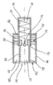
- a particularly preferred embodiment of the invention with reference to the single figure, which comprises a clamping device 100 with a housing 102 and a movable therein arranged spring force and hydraulically operated clamping piston 114, explained in more detail.
- the present clamping device 100 cooperates with a tensioning rail of a chain drive for driving camshafts of an internal combustion engine not shown here in detail.
- the housing 102 of the clamping device 100 is cylindrical in shape and comprises an outer jacket 104, an inner jacket 106 and a bottom 103, from which the inner jacket 106 extends.
- the bottom 103 facing away from the end of the inner shell 106 has an opening in which a check valve 116 is arranged.
- annular space 112 Between outer shell 104 and inner shell 106 is an annular space 112, within the inner shell 106, a cylindrical space 110 is formed.
- the spaces 110, 112 are referred to as low pressure space and are connected via bore 108 with each other.
- a clamping piston 114 is guided longitudinally displaceable, wherein the clamping piston 114 is configured cylindrical-cup-shaped and with its open end the inner shell 104 engages to form a leakage gap 120.
- a high-pressure chamber 130 is formed within the clamping piston 114.
- the clamping piston 114 is in the clamping direction, according to its extended position, by means of a tensioning piston return spring 118 subjected to force.
- the annular low pressure space 112 is limited at its end remote from the housing bottom 103 by an annular compensating piston 122.
- the compensating piston 122 is subjected to a force in the direction of the housing bottom 103 by means of a compensating spring 124, which is supported on the compensating piston 122 on the one hand and on the housing end facing away from the housing bottom 103 on the other hand.
- the compensating spring chamber 125 has holes 126 for pressure equalization.
- the low-pressure chambers 110, 112 and the high-pressure chamber 130 of the clamping device 100 are completely filled with a hydraulic medium, for example a hydraulic oil.
- a dynamic force acts on the tensioning piston 114 via the tensioning rail.
- the check valve 116 blocks a hydraulic fluid flow from the high-pressure space 130 to the low-pressure space 110, so that pressure is applied to the hydraulic medium in the high-pressure space 130.
- a hydraulic damping of the spring-loaded clamping piston 114 is achieved via the leakage gap 120 formed between the inner shell 106 and the clamping piston 114 by allowing a defined leakage current from the high-pressure chamber 130 into the low-pressure chamber 112 when the clamping piston 114 is loaded.
- the restoring spring 118 relaxes and hydraulic medium flows from the low-pressure space 110 into the high-pressure space 130 via the check valve 116.
- the hydraulic medium located in the low-pressure space 110, 112 and in the high-pressure chamber 130 assumes a larger volume at a higher temperature than at a low temperature.
- An operation-related elongation of the traction means requires further extension of the clamping piston 114 in the clamping direction in order to maintain the tension in the traction means. Owing to Temperature changes and wear, therefore, a volume compensation is needed. This compensation takes place here by means of the compensating piston 122, which is biased by a compensating spring 124. If the hydraulic medium expands due to the heating, the compensating spring 124 is pretensioned via the compensating piston 122.
- the compensating piston 122 shifts under the force of the compensating spring 124 in the direction of the housing bottom 103, the volume in the low-pressure chamber 112 being reduced. A pressure equalization in the space 125 via holes 126.
- the balance piston 122 is particularly well sealed.
- the clamping piston 114 in the inner shell 106 is guided on the inside, so that the compensating piston 122 is guided on the inside of the outer shell 104 on the one hand and on the outside of the inner shell 106 on the other hand.
- This arrangement offers advantages in terms of the tightness of the balance piston 122.
Landscapes
- Engineering & Computer Science (AREA)
- General Engineering & Computer Science (AREA)
- Mechanical Engineering (AREA)
- Devices For Conveying Motion By Means Of Endless Flexible Members (AREA)
Abstract
Description
- Die Erfindung betrifft eine hydraulische Spanneinrichtung für ein Zugmittelgetriebe, insbesondere Kettentrieb einer Brennkraftmaschine, umfassend ein Gehäuse und einen darin beweglich angeordneten federkraft- und hydraulisch beaufschlagten Spannkolben.
- Eine derartige Spanneinrichtung ist beispielsweise aus der
DE 40 35 823 C1 bekannt, der zufolge ein hydraulisch beaufschlagbarer Spannkolben zum Spannen eines Zugmittelgetriebes dient. - Eine hydraulische Dämpfung des federbelasteten Spannkolbens wird gemäß der
DE 40 35 823 C1 bei üblichen Belastungen durch Verdrängen von Hydraulikmedium aus einer Dämpfungskammer über einen zwischen Spannkolben und dessen Führungsbuchse gebildeten Leckspalt erzielt, wobei die Leckagemenge an Hydraulikmedium über ein Rückschlagventil aus einem Vorratsraum beim Ausfahren des Spannkolbens in Spannrichtung ersetzt wird. Der Vorratsraum steht über eine Zulaufbohrung im Spannkolben und einen Zulauf in der Führungsbuchse mit einem Druckanschluss, welcher an das Druck-Schmiersystem der Brennkraftmaschine angeschlossen ist, in Verbindung. - Diese bekannte Spanneinrichtung benötigt eine Versorgung mit Hydraulikmedium, wobei ein vorbestimmter Volumenstrom und ein vorbestimmter Mindestdruck Voraussetzung für ein einwandfreies Funktionieren der Spanneinrichtung sind. Die Spanneinrichtung ist erst dann vollständig betriebsfähig, wenn das Hydraulikmedium mit einem vorbestimmten Mindestdruck am Druckanschluss anliegt.
- Die aus der
DE 40 35 823 C1 bekannte Spanneinrichtung benötigt eine eigene Versorgung mit Hydraulikmedium, außerdem muss, da sie an das Druck-Schmiersystem der Brennkraftmaschine angeschlossen ist, dieses unter Berücksichtigung der Spanneinrichtung ausgelegt werden. - Beim Starten der Brennkraftmaschine muss in der Spanneinrichtung vom Druck-Schmiersystem zunächst ein ausreichend hoher Schmiermitteldruck aufgebaut werden, bevor die Spanneinrichtung funktionsfähig ist. Während der Startphase kann das Zugmittelgetriebe ungespannt oder nicht ausreichend gespannt laufen mit der Folge einer unerwünschten Geräuschentwicklung, von Übertragungsungenauigkeiten im Zugmittelgetriebe und eines übermäßigen Verschleißes des Zugmittels.
- Der Erfindung liegt daher die Aufgabe zugrunde, eine eingangs genannte Spanneinrichtung bereitzustellen, welche keine gesonderte Versorgung mit Hydraulikmedium benötigt und welche bereits beim Starten der Brennkraftmaschine voll funktionsfähig ist. Darüber hinaus soll eine Auslegung des Druck-Schmiersystems der Brennkraftmaschine von der Spanneinrichtung unabhängig ermöglicht werden.
- Die Lösung der Aufgabe erfolgt mit einer hydraulischen Spanneinrichtung mit den Merkmalen des Anspruchs 1, wobei die Idee zugrunde liegt, die Spanneinrichtung hydraulisch geschlossen auszugestalten. Dadurch ist es möglich, die Spanneinrichtung mit Hydraulikmedium vorzufüllen, wobei ein Betrieb der Spanneinrichtung mit diesem in der Spanneinrichtung vorhandenen Menge Hydraulikmedium erfolgt.
- Besonders zu bevorzugende Ausführungen der Erfindung sind Gegenstand der Unteransprüche.
- Vorzugsweise umfasst die erfindungsgemäße Spanneinrichtung eine Einrichtung zum Ausgleich des abgeschlossenen Hydraulikvolumens. Damit ist es möglich, temperatur- und/oder verschleißbedingte Volumenänderungen auszugleichen.
- Sehr vorteilhaft ist es, wenn die Volumenausgleichseinrichtung einen federkraftbeaufschlagten Ausgleichskolben umfasst. Auf diese Weise ist ein Volumenausgleich ohne Zu- oder Abfuhr von Hydraulikmedium möglich.
- Gemäß einer besonders bevorzugten Ausgestaltung der Erfindung ist bei einer Spanneinrichtung, bei welcher im Gehäuse ein Hochdruckraum und ein Niederdruckraum gebildet sind, der Spannkolben dem Hochdruckraum zugeordnet und längs geführt ist, zwischen Hochdruckraum und Niederdruckraum ein Rückschlagventil angeordnet ist und zwischen Spannkolben und dessen Längsführung ein Leckspalt gebildet ist, der Ausgleichskolben zum Ausgleich des Niederdruckraumvolumens geeignet.
- Zweckmäßigerweise umfasst das Gehäuse einen Außenmantel und einen Innenmantel, wobei der Spannkolben außenseitig des Innenmantels und der Ausgleichskolben zwischen Außenmantel und Spannkolben geführt ist. Einem anderen, ebenfalls bevorzugten Ausführungsbeispiel zufolge umfasst das Gehäuse einen Außenmantel und einen Innenmantel, wobei der Spannkolben innenseitig des Innenmantels und der Ausgleichskolben zwischen Außen- und Innenmantel geführt ist.
- Nachfolgend wird ein besonders zu bevorzugendes Ausführungsbeispiel der Erfindung unter Bezugnahme auf die einzige Figur, welche eine Spanneinrichtung 100 mit einem Gehäuse 102 und einem darin beweglich angeordneten federkraft- und hydraulisch beaufschlagten Spannkolben 114 umfasst, näher erläutert.
- Die vorliegende Spanneinrichtung 100 wirkt mit einer Spannschiene eines Kettentriebs zum Antrieb von Nockenwellen einer hier nicht näher gezeigten Brennkraftmaschine zusammen.
- Das Gehäuse 102 der Spanneinrichtung 100 ist zylinderförmig gestaltet und umfasst einen Außenmantel 104, einen Innenmantel 106 und einen Boden 103, von dem aus sich der Innenmantel 106 erstreckt. Das dem Boden 103 abgewandte Ende des Innenmantels 106 weist eine Öffnung auf, in welcher ein Rückschlagventil 116 angeordnet ist. Zwischen Außenmantel 104 und Innenmantel 106 ist ein Ringraum 112, innerhalb des Innenmantels 106 ist ein zylindrischer Raum 110 gebildet. Die Räume 110, 112 werden als Niederdruckraum bezeichnet und sind über Bohrung 108 miteinander verbunden.
- Am Innenmantel 104 ist ein Spannkolben 114 längsverschieblich geführt, wobei der Spannkolben 114 zylindrisch-topfförmig ausgestaltet ist und mit seinem offenen Ende den Innenmantel 104 umgreift unter Bildung eines Leckspalts 120. Innerhalb des Spannkolbens 114 ist ein Hochdruckraum 130 gebildet. Der Spannkolben 114 ist in Spannrichtung, entsprechend seiner ausgefahrenen Stellung, mittels einer Spannkolbenrückstellfeder 118 kraftbeaufschlagt.
- Der ringförmige Niederdruckraum 112 wird an seinem dem Gehäuseboden 103 abgewandten Ende von einem ringförmigen Ausgleichskolben 122 begrenzt. Der Ausgleichskolben 122 ist in Richtung des Gehäusebodens 103 mittels einer Ausgleichsfeder 124, welche sich am Ausgleichskolben 122 einerseits und an dem dem Gehäuseboden 103 abgewandten Gehäuseende andererseits abstützt, kraftbeaufschlagt. Der Ausgleichsfederraum 125 weist Bohrungen 126 zum Druckausgleich auf.
- Die Niederdruckräume 110, 112 sowie der Hochdruckraum 130 der Spanneinrichtung 100 sind mit einem Hydraulikmedium, beispielsweise einem Hydrauliköl, vollständig gefüllt. Im Betrieb wirkt eine dynamische Kraft über die Spannschiene auf den Spannkolben 114. Das Rückschlagventil 116 sperrt einen Hydraulikmediumfluss vom Hochdruckraum 130 zum Niederdruckraum 110, sodass dabei im Hochdruckraum 130 befindliches Hydraulikmedium druckbelastet wird. Eine hydraulische Dämpfung des federbelasteten Spannkolbens 114 wird über den zwischen Innenmantel 106 und Spannkolben 114 gebildeten Leckspalt 120 erreicht, indem bei Belastung des Spannkolbens 114 ein definierter Leckstrom vom Hochdruckraum 130 in den Niederdruckraum 112 ermöglicht ist.
- Sobald die auf den Spannkolben 114 wirkende Kraft geringer wird, beispielsweise aufgrund eines Wechselmoments des Ventiltriebs, entspannt die Rückstellfeder 118 und über das Rückschlagventil 116 fließt Hydraulikmedium vom Niederdruckraum 110 in den Hochdruckraum 130.
- Das im Niederdruckraum 110, 112 sowie im Hochdruckraum 130 befindliche Hydraulikmedium nimmt bei höherer Temperatur ein größeres Volumen ein als bei niedriger Temperatur. Eine betriebsbedingte Längung des Zugmittels erfordert ein weiteres Ausfahren des Spannkolbens 114 in Spannrichtung, um die Spannung im Zugmittel aufrecht zu erhalten. Aufgrund von Temperaturänderungen und verschleißbedingt wird daher ein Volumenausgleich benötigt. Dieser Ausgleich erfolgt vorliegend mittels des Ausgleichkolbens 122, welcher über eine Ausgleichsfeder 124 vorgespannt ist. Dehnt sich das Hydraulikmedium aufgrund der Erwärmung aus, so wird die Ausgleichsfeder 124 über den Ausgleichskolben 122 vorgespannt. Fährt der Spannkolben 114 aufgrund von Verschleiß im Zugmittel weiter aus, so verlagert sich der Ausgleichskolben 122 unter der Kraft der Ausgleichsfeder 124 in Richtung des Gehäusebodens 103, wobei das Volumen im Niederdruckraum 112 verringert wird. Ein Druckausgleich im Raum 125 erfolgt über Bohrungen 126. Der Ausgleichskolben 122 ist besonders gut dichtend ausgeführt.
- Einem anderen, hier nicht gezeigten Ausführungsbeispiel zufolge ist der Spannkolben 114 im Innenmantel 106 innenseitig geführt, sodass der Ausgleichskolben 122 innenseitig des Außenmantels 104 einerseits und außenseitig des Innenmantels 106 andererseits geführt ist. Diese Anordnung bietet Vorteile hinsichtlich der Dichtigkeit des Ausgleichskolbens 122.
Claims (6)
- Hydraulische Spanneinrichtung (100) für ein Zugmittelgetriebe, insbesondere Kettentrieb einer Brennkraftmaschine, umfassend ein Gehäuse (102) und einen darin beweglich angeordneten federkraft- und hydraulisch beaufschlagten Spannkolben (114), dadurch gekennzeichnet, dass die Spanneinrichtung (100) hydraulisch geschlossen ist.
- Spanneinrichtung (100) nach Anspruch 1, gekennzeichnet durch eine Einrichtung (128) zum Ausgleich des abgeschlossenen Hydraulikvolumens (110, 112, 130).
- Spanneinrichtung (100) nach einem der vorhergehenden Ansprüche, dadurch gekennzeichnet, dass die Volumenausgleichseinrichtung (128) einen federkraftbeaufschlagten Ausgleichskolben (122) umfasst.
- Spanneinrichtung (100) nach einem der vorhergehenden Ansprüche, wobei- im Gehäuse (102) ein Hochdruckraum (130) und ein Niederdruckraum (110, 112) gebildet sind,- der Spannkolben (114) dem Hochdruckraum (130) zugeordnet und längs geführt ist,- zwischen Hochdruckraum (130) und Niederdruckraum (110) ein Rückschlagventil (116) angeordnet ist und- zwischen Spannkolben (114) und dessen Längsführung ein Leckspalt (120) gebildet ist,dadurch gekennzeichnet, dass der Ausgleichskolben (122) zum Ausgleich des Niederdruckraumvolumens (112) geeignet ist.
- Spanneinrichtung (100) nach einem der vorhergehenden Ansprüche, dadurch gekennzeichnet, dass das Gehäuse (102) einen Außenmantel (104) und einen Innenmantel (106) umfasst, wobei der Spannkolben (114) außenseitig des Innenmantels (106) und der Ausgleichskolben (122) zwischen Außenmantel (104) und Spannkolben (114) geführt ist.
- Spanneinrichtung (100) nach einem der vorhergehenden Ansprüche, dadurch gekennzeichnet, dass das Gehäuse (102) einen Außenmantel (104) und einen Innenmantel (106) umfasst, wobei der Spannkolben (114) innenseitig des Innenmantels (106) und der Ausgleichskolben (122) zwischen Außen- und Innenmantel (104, 106) geführt ist.
Applications Claiming Priority (1)
| Application Number | Priority Date | Filing Date | Title |
|---|---|---|---|
| DE200710018961 DE102007018961A1 (de) | 2007-04-21 | 2007-04-21 | Hydraulische Spanneinrichtung für ein Zugmittelgetriebe |
Publications (3)
| Publication Number | Publication Date |
|---|---|
| EP1983218A2 true EP1983218A2 (de) | 2008-10-22 |
| EP1983218A3 EP1983218A3 (de) | 2009-05-20 |
| EP1983218B1 EP1983218B1 (de) | 2011-06-22 |
Family
ID=39591958
Family Applications (1)
| Application Number | Title | Priority Date | Filing Date |
|---|---|---|---|
| EP20080004889 Not-in-force EP1983218B1 (de) | 2007-04-21 | 2008-03-15 | Hydraulische Spanneinrichtung für ein Zugmittelgetriebe |
Country Status (3)
| Country | Link |
|---|---|
| EP (1) | EP1983218B1 (de) |
| DE (1) | DE102007018961A1 (de) |
| ES (1) | ES2364785T3 (de) |
Families Citing this family (1)
| Publication number | Priority date | Publication date | Assignee | Title |
|---|---|---|---|---|
| JP6940772B2 (ja) * | 2018-02-16 | 2021-09-29 | 株式会社椿本チエイン | チェーンテンショナ |
Citations (2)
| Publication number | Priority date | Publication date | Assignee | Title |
|---|---|---|---|---|
| DE4035823C1 (en) | 1990-11-10 | 1991-12-19 | Bayerische Motoren Werke Ag, 8000 Muenchen, De | Hydraulic tensioner for chain drives - has pressure restrictor valve in bottom of tension piston guide |
| DE19943402A1 (de) | 1998-09-11 | 2000-04-20 | Aisin Seiki | Selbstspanner |
Family Cites Families (9)
| Publication number | Priority date | Publication date | Assignee | Title |
|---|---|---|---|---|
| JPS63120949A (ja) * | 1986-11-06 | 1988-05-25 | Aisin Seiki Co Ltd | フリ−ピストン型オ−トテンシヨナ |
| DE3915227A1 (de) * | 1988-06-18 | 1989-12-21 | Schroeder Werner | Vorrichtung zum spannen von treibriemen, insbesondere fuer kraftfahrzeuge |
| JP2751251B2 (ja) * | 1988-10-31 | 1998-05-18 | 三菱自動車工業株式会社 | タイミングベルト用オートテンショナー |
| JPH0349453U (de) * | 1989-09-22 | 1991-05-14 | ||
| JPH07280050A (ja) * | 1994-04-01 | 1995-10-27 | Tsubakimoto Chain Co | オイル密封式テンショナのダイヤフラム異常変形防止構造 |
| JP2000145904A (ja) * | 1998-11-16 | 2000-05-26 | Aisin Seiki Co Ltd | フリーピストン型オートテンショナ |
| ITMI20021243A1 (it) * | 2002-06-07 | 2003-12-09 | Regina Ind Spa | Tenditore a fluido per catena |
| DE10327214A1 (de) * | 2003-06-17 | 2005-01-13 | Ina-Schaeffler Kg | Spann- und Dämpfungselement für Zugmitteltriebe |
| DE10359641A1 (de) * | 2003-12-18 | 2005-07-28 | Ina-Schaeffler Kg | Aggregatetrieb für eine Brennkraftmaschine mit einem Startergenerator |
-
2007
- 2007-04-21 DE DE200710018961 patent/DE102007018961A1/de not_active Withdrawn
-
2008
- 2008-03-15 ES ES08004889T patent/ES2364785T3/es active Active
- 2008-03-15 EP EP20080004889 patent/EP1983218B1/de not_active Not-in-force
Patent Citations (2)
| Publication number | Priority date | Publication date | Assignee | Title |
|---|---|---|---|---|
| DE4035823C1 (en) | 1990-11-10 | 1991-12-19 | Bayerische Motoren Werke Ag, 8000 Muenchen, De | Hydraulic tensioner for chain drives - has pressure restrictor valve in bottom of tension piston guide |
| DE19943402A1 (de) | 1998-09-11 | 2000-04-20 | Aisin Seiki | Selbstspanner |
Also Published As
| Publication number | Publication date |
|---|---|
| DE102007018961A1 (de) | 2008-10-23 |
| EP1983218A3 (de) | 2009-05-20 |
| ES2364785T3 (es) | 2011-09-14 |
| EP1983218B1 (de) | 2011-06-22 |
Similar Documents
| Publication | Publication Date | Title |
|---|---|---|
| EP0468085B1 (de) | Kettenspanner für eine Brennkraftmaschine | |
| EP1373718B1 (de) | Druckbegrenzungsventil für kraftstoff-einspritzeinrichtungen | |
| EP2567095B1 (de) | Schmierstoffventil für ölpumpen von verbrennungsmotoren | |
| DE19930868A1 (de) | Ventil | |
| DE3922037A1 (de) | Spannvorrichtung fuer ketten- oder riementriebe | |
| DE4035823C1 (en) | Hydraulic tensioner for chain drives - has pressure restrictor valve in bottom of tension piston guide | |
| DE102013111616A1 (de) | Umschaltventil und Verbrennungsmotor mit einem solchen Umschaltventil | |
| WO2017059851A9 (de) | Hydraulische spannvorrichtung für einen kettentrieb | |
| EP0428581B1 (de) | Hydrostatischer antrieb für fahrzeuge | |
| DE102008014152B4 (de) | Hydropulsvorrichtung und Verfahren zur Erzeugung eines zeitvarianten Fluiddrucks mittels einer Hydropulsvorrichtung | |
| EP1983218B1 (de) | Hydraulische Spanneinrichtung für ein Zugmittelgetriebe | |
| DE102004054108B4 (de) | Dreiwegeventil und dieses aufweisende Brennstoffeinspritzvorrichtung | |
| DE102009034047A1 (de) | Kettenantriebsspanner mit variablem Durchlass | |
| WO2003001037A1 (de) | Hydraulisches spielausgleichselement für einen ventiltrieb eines verbrennungsmotors | |
| EP2694816B1 (de) | Luftregler für kompressoren, insbesondere schraubenkompressoren | |
| DE102019217254A1 (de) | System und Verfahren zum Einstellen einer wirksamen Länge einer Pleuelstange sowie Brennkraftmaschine | |
| DE112019001146T5 (de) | Kettenspanner | |
| EP1476678B1 (de) | Spannvorrichtung mit spanndruck-regelventil | |
| DE102018119654A1 (de) | Hubkolbenmaschine mit variablem Verdichtungsverhältnis | |
| DE102010006411A1 (de) | Hydraulischer Ventiltrieb einer Brennkraftmaschine | |
| AT521675B1 (de) | Hydraulisches Steuerventil für eine längenverstellbare Pleuelstange mit zwei stirnseitigen Steuerkolben | |
| DE3106610A1 (de) | Spuelventil | |
| EP3267012A1 (de) | Rückschlagventil für einen pleuel für eine brennkraftmaschine mit variabler verdichtung | |
| DE19508561C2 (de) | Schraubenspindelpumpe | |
| DE102010006412A1 (de) | Hydraulischer Ventiltrieb einer Brennkraftmaschine |
Legal Events
| Date | Code | Title | Description |
|---|---|---|---|
| PUAI | Public reference made under article 153(3) epc to a published international application that has entered the european phase |
Free format text: ORIGINAL CODE: 0009012 |
|
| AK | Designated contracting states |
Kind code of ref document: A2 Designated state(s): AT BE BG CH CY CZ DE DK EE ES FI FR GB GR HR HU IE IS IT LI LT LU LV MC MT NL NO PL PT RO SE SI SK TR |
|
| AX | Request for extension of the european patent |
Extension state: AL BA MK RS |
|
| PUAL | Search report despatched |
Free format text: ORIGINAL CODE: 0009013 |
|
| AK | Designated contracting states |
Kind code of ref document: A3 Designated state(s): AT BE BG CH CY CZ DE DK EE ES FI FR GB GR HR HU IE IS IT LI LT LU LV MC MT NL NO PL PT RO SE SI SK TR |
|
| AX | Request for extension of the european patent |
Extension state: AL BA MK RS |
|
| 17P | Request for examination filed |
Effective date: 20090609 |
|
| 17Q | First examination report despatched |
Effective date: 20090714 |
|
| AKX | Designation fees paid |
Designated state(s): DE ES FR GB IT |
|
| GRAP | Despatch of communication of intention to grant a patent |
Free format text: ORIGINAL CODE: EPIDOSNIGR1 |
|
| GRAS | Grant fee paid |
Free format text: ORIGINAL CODE: EPIDOSNIGR3 |
|
| GRAA | (expected) grant |
Free format text: ORIGINAL CODE: 0009210 |
|
| AK | Designated contracting states |
Kind code of ref document: B1 Designated state(s): DE ES FR GB IT |
|
| REG | Reference to a national code |
Ref country code: GB Ref legal event code: FG4D Free format text: NOT ENGLISH |
|
| REG | Reference to a national code |
Ref country code: DE Ref legal event code: R096 Ref document number: 502008003915 Country of ref document: DE Effective date: 20110728 |
|
| REG | Reference to a national code |
Ref country code: ES Ref legal event code: FG2A Ref document number: 2364785 Country of ref document: ES Kind code of ref document: T3 Effective date: 20110914 |
|
| PLBE | No opposition filed within time limit |
Free format text: ORIGINAL CODE: 0009261 |
|
| STAA | Information on the status of an ep patent application or granted ep patent |
Free format text: STATUS: NO OPPOSITION FILED WITHIN TIME LIMIT |
|
| 26N | No opposition filed |
Effective date: 20120323 |
|
| REG | Reference to a national code |
Ref country code: DE Ref legal event code: R097 Ref document number: 502008003915 Country of ref document: DE Effective date: 20120323 |
|
| REG | Reference to a national code |
Ref country code: FR Ref legal event code: PLFP Year of fee payment: 9 |
|
| REG | Reference to a national code |
Ref country code: FR Ref legal event code: PLFP Year of fee payment: 10 |
|
| REG | Reference to a national code |
Ref country code: FR Ref legal event code: PLFP Year of fee payment: 11 |
|
| PGFP | Annual fee paid to national office [announced via postgrant information from national office to epo] |
Ref country code: GB Payment date: 20190325 Year of fee payment: 12 Ref country code: DE Payment date: 20190321 Year of fee payment: 12 Ref country code: IT Payment date: 20190321 Year of fee payment: 12 Ref country code: FR Payment date: 20190326 Year of fee payment: 12 |
|
| PGFP | Annual fee paid to national office [announced via postgrant information from national office to epo] |
Ref country code: ES Payment date: 20190424 Year of fee payment: 12 |
|
| REG | Reference to a national code |
Ref country code: DE Ref legal event code: R119 Ref document number: 502008003915 Country of ref document: DE |
|
| PG25 | Lapsed in a contracting state [announced via postgrant information from national office to epo] |
Ref country code: FR Free format text: LAPSE BECAUSE OF NON-PAYMENT OF DUE FEES Effective date: 20200331 Ref country code: DE Free format text: LAPSE BECAUSE OF NON-PAYMENT OF DUE FEES Effective date: 20201001 |
|
| GBPC | Gb: european patent ceased through non-payment of renewal fee |
Effective date: 20200315 |
|
| PG25 | Lapsed in a contracting state [announced via postgrant information from national office to epo] |
Ref country code: GB Free format text: LAPSE BECAUSE OF NON-PAYMENT OF DUE FEES Effective date: 20200315 |
|
| REG | Reference to a national code |
Ref country code: ES Ref legal event code: FD2A Effective date: 20210802 |
|
| PG25 | Lapsed in a contracting state [announced via postgrant information from national office to epo] |
Ref country code: IT Free format text: LAPSE BECAUSE OF NON-PAYMENT OF DUE FEES Effective date: 20200315 |
|
| PG25 | Lapsed in a contracting state [announced via postgrant information from national office to epo] |
Ref country code: ES Free format text: LAPSE BECAUSE OF NON-PAYMENT OF DUE FEES Effective date: 20200316 |
|
| P01 | Opt-out of the competence of the unified patent court (upc) registered |
Effective date: 20230502 |