EP1983125A2 - Dichtungsvorrichtung - Google Patents
Dichtungsvorrichtung Download PDFInfo
- Publication number
- EP1983125A2 EP1983125A2 EP08154694A EP08154694A EP1983125A2 EP 1983125 A2 EP1983125 A2 EP 1983125A2 EP 08154694 A EP08154694 A EP 08154694A EP 08154694 A EP08154694 A EP 08154694A EP 1983125 A2 EP1983125 A2 EP 1983125A2
- Authority
- EP
- European Patent Office
- Prior art keywords
- sealing
- tendon
- sealing device
- duct
- concrete
- Prior art date
- Legal status (The legal status is an assumption and is not a legal conclusion. Google has not performed a legal analysis and makes no representation as to the accuracy of the status listed.)
- Withdrawn
Links
- 238000007789 sealing Methods 0.000 title claims abstract description 127
- 239000004567 concrete Substances 0.000 claims abstract description 61
- 210000002435 tendon Anatomy 0.000 claims abstract description 47
- 238000000034 method Methods 0.000 claims abstract description 13
- 239000011178 precast concrete Substances 0.000 claims abstract description 8
- 238000010276 construction Methods 0.000 claims description 14
- 239000000463 material Substances 0.000 claims description 10
- 239000007788 liquid Substances 0.000 claims description 9
- 239000012530 fluid Substances 0.000 claims description 3
- 229920001971 elastomer Polymers 0.000 claims description 2
- 229920000642 polymer Polymers 0.000 claims description 2
- 229920002635 polyurethane Polymers 0.000 claims description 2
- 239000004814 polyurethane Substances 0.000 claims description 2
- XLYOFNOQVPJJNP-UHFFFAOYSA-N water Substances O XLYOFNOQVPJJNP-UHFFFAOYSA-N 0.000 claims description 2
- 230000009182 swimming Effects 0.000 claims 1
- 239000004570 mortar (masonry) Substances 0.000 description 6
- 230000006835 compression Effects 0.000 description 5
- 238000007906 compression Methods 0.000 description 5
- 238000005260 corrosion Methods 0.000 description 4
- 230000007797 corrosion Effects 0.000 description 4
- 239000004519 grease Substances 0.000 description 3
- 238000002347 injection Methods 0.000 description 3
- 239000007924 injection Substances 0.000 description 3
- 101700004678 SLIT3 Proteins 0.000 description 2
- 102100027339 Slit homolog 3 protein Human genes 0.000 description 2
- 239000012528 membrane Substances 0.000 description 2
- 230000002787 reinforcement Effects 0.000 description 2
- 238000004873 anchoring Methods 0.000 description 1
- QVGXLLKOCUKJST-UHFFFAOYSA-N atomic oxygen Chemical compound [O] QVGXLLKOCUKJST-UHFFFAOYSA-N 0.000 description 1
- 230000001627 detrimental effect Effects 0.000 description 1
- 230000003292 diminished effect Effects 0.000 description 1
- 230000009972 noncorrosive effect Effects 0.000 description 1
- 239000001301 oxygen Substances 0.000 description 1
- 229910052760 oxygen Inorganic materials 0.000 description 1
- 239000004033 plastic Substances 0.000 description 1
- 229920003023 plastic Polymers 0.000 description 1
- 229920000915 polyvinyl chloride Polymers 0.000 description 1
- 239000000243 solution Substances 0.000 description 1
- 239000000126 substance Substances 0.000 description 1
Images

Classifications
-
- E—FIXED CONSTRUCTIONS
- E04—BUILDING
- E04C—STRUCTURAL ELEMENTS; BUILDING MATERIALS
- E04C5/00—Reinforcing elements, e.g. for concrete; Auxiliary elements therefor
- E04C5/08—Members specially adapted to be used in prestressed constructions
- E04C5/10—Ducts
-
- E—FIXED CONSTRUCTIONS
- E04—BUILDING
- E04C—STRUCTURAL ELEMENTS; BUILDING MATERIALS
- E04C5/00—Reinforcing elements, e.g. for concrete; Auxiliary elements therefor
- E04C5/08—Members specially adapted to be used in prestressed constructions
- E04C5/12—Anchoring devices
Definitions
- the present invention relates to a method of reliable sealing of duct-system in concrete structures as well as an annular sealing device used in such method.
- Pre-stressed or stressed concrete structures are a well-known and widespread method for constructing concrete structures, where particular use is made of the compressive characteristics of the concrete material.
- the pre-stressing or stressing of the concrete may assure that there will always be compression over the entire cross section of the concrete construction.
- This is particularly interesting for constructions which may exposed to an aggressive environment in that concrete has superior compressibility characteristics whereas tension usually causes cracks in the concrete structure. These cracks may expose the reinforcement whereafter the aggressive environment might corrode the reinforcement so that the ability of the construction to withstand tension forces is diminished which may ultimately cause failure of the entire construction. It is therefore a common practice to use pre-stressed or stressed or post-tensioned concrete structures, and in the art a number of different systems exist by which to stress such concrete structures.
- cables or strings are used, which cables are arranged in special ducts going through the concrete structure in the direction where it is desirable to achieve the compression in the concrete.
- the ducts in which the cables are placed are injected with a mortar in order to protect the cables from corrosion. This is particularly true, when the concrete structures may be exposed to moisture or liquid in that the presence of moisture or liquid and oxygen may cause corrosive action in the cables whereby the cable may not over time be able to withstand the tension applied to the cables in order to provide compression in the concrete cross sections.
- the injection of mortar in the cable ducts may have a number of advantages, but it may also have a number of disadvantages in that if the concrete structure as such is exposed to dynamic forces or other types of movements, for example due to thermal exposure, the mortar in the ducts may crack and thereby give access to seeping moisture which may have a detrimental effect on the cables in the ducts.
- the present invention addresses this by a method of sealing cable ducts in a pre-stressed or post-tensioned concrete structure, for example a pre-cast concrete panel, wherein a sealing device is fitted around the cable, where said sealing device has an annular shape with a substantially centrally placed aperture, where the aperture has a size substantially corresponding to the outside size of the cable, and where the outer dimension of the sealing member has a size substantially corresponding to the inner size of the duct, and where the sealing member is suitable to be inserted partly into the duct.
- the sealing element may therefore be compared to a plug where centrally in the plug an aperture is provided.
- the aperture has a size substantially corresponding to the outside of the cable, but so that it has a sealing engagement with the cable.
- the cable will naturally have a longitudinal extent and the extent of the sealing member in the longitudinal direction must be sufficient in order to assure that there will be enough contact surface between the outside of the cable and the inside of the aperture provided in the sealing member in order to create a liquid-tight connection.
- the outside diameter of the sealing member may be pre-made in sizes which will fit to the limited number of duct sizes.
- cables In the art a number of more or less standardized cable sizes are used, and a number of these cables are made out of a number of twisted strands, for example seven, which are covered in grease and thereafter provided with a sheeting, e.g. in the shape of a pvc-membrane, pe-membrane or the like.
- the contact between the inner surface of the aperture of the sealing member must therefore be suitable to create a liquid-tight contact with the outside surface of the tension cable.
- the invention furthermore provides a method of sealing a cable duct between two adjacent panels in a pre-cast concrete structure, wherein a first sealing device is arranged around the cable, where said element has an annular shape, such that the cable may sealingly fit inside the sealing device and the outside of the sealing device may partly fit inside the duct in the concrete panel, such that a part of the sealing element extends outside the duct, and when the cable is tensioned and two adjacent concrete panels are forced together due to the tension in the cable, the sealing member will abut the adjacent panel at the joint, or a similar sealing device arranged in the adjacent element, and the tension in the cable will force the concrete panels together and thereby deform the sealing devices, thereby creating a sealing of the duct.
- the pre-cast concrete panels will be forced together and thereby abut the sealing device arranged around the cable.
- the contact between the concrete panel and the sealing element will cause the sealing element to deform and thereby completely seal the duct opening simply by the compression applied by the concrete panels in response to the tensioning of the cables in the cable ducts.
- a second sealing member is provided, where said second sealing member has a rectangular shape and extent, substantially corresponding to the surfaces of adjacent panels to be assembled, where said second sealing member is provided with apertures corresponding and placed superposed the cable duct in the panels, and where, when the cable(s) is(are) tensioned and the two concrete panels forced together, the first sealing elements will abut the second sealing elements, and together the first and second sealing elements will create a substantially liquid-tight seal between the two concrete panels and the ducts.
- the first sealing member serves to seal off the ducts in which the cables are placed, and the second sealing member serves to seal between two adjacent concrete panels, so that a completely liquid-tight construction may be achieved.
- the second sealing member is traditionally used in order to provide a liquid-tight seal between two adjacent concrete constructions, but leaves out the sealing of the ducts in which the cables are placed so that the corrosion problems as mentioned above if only a seal, here called the second sealing member is provided. Therefore, by combining the sealing of the ducts together with the sealing of the connection between two adjacent concrete panels a completely liquid-tight seal is achieved so that the construction may be used for example by erecting a tank, swimming-pool or the like, where it is desirable to retain a liquid inside the construction.
- pre-cast concrete panels are part of a swimming-pool, bridge, basement construction, water retaining tank or the like.
- the sealing device projects between 3 mm and 10 mm out from the duct in the direction of the cable.
- the invention is also directed to an annular sealing element as such, e.g. for use in a method as described above.
- This sealing device is particular in that the element has an inner and outer diameter, where the inner diameter is dimensioned such that the sealing member will sealingly fit around a cable, and the outer diameter will substantially fit inside a duct in a concrete panel.
- the device is made from a resistant material, such as rubber, polyurethane, PVC, PP, PE or other polymer based material.
- the resistant characteristics of the materials make it possible for the sealing device to adapt to inaccuracies etc. when the tension is applied to the cables and the concrete panels are forced together so that a complete and reliable seal may be attained between the sealing device and the walls of the duct.
- the sealing device comprises an outer shell surrounding an inner volume, where the shell is made from a resistant material, and the inner volume is filled with a deformable fluid.
- the deformability of the seal increases so that a further security of absolute sealing properties between the cable and the duct is achieved.
- the sealing device is in the shape of a cone, such that the largest outer diameter of the sealing element is larger than the diameter of the duct in the concrete panel.
- the device is C-shaped, such that the device may be pushed sideways over and fitted around the cable.
- Post-tensioned constructions are typically constructions which after or during assembly are fitted with tendons and thereafter tensioned.
- the "post” therefore refers to an action after the concrete element has been cast.
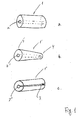
- FIG 1a a sealing device having a cylindrical shape where the sealing element 1 is provided with an aperture 2.
- the aperture has a size corresponding to the tendon which is supposed to be arranged inside the aperture so that between the aperture and the tendon a sealing connection will be achieved.
- the aperture 2 extends through the length of the element as illustrated by the phantom lines.
- a sealing device 1' also provided with an aperture 2', but in this embodiment of the invention the sealing device 1' has a conical shape such that a first end 4 of the sealing element is suitable to be inserted into the tendon duct in the concrete panel and the second end 5 has a size larger than the diameter of the duct such that a portion of the sealing device 1' will extend outside the tendon duct.
- FIG 1c is illustrated an embodiment of the sealing device, where the device has a substantial C-shape in that a slit 3 is provided in the longitudinal direction of the sealing device 1" connecting the substantially centrally placed aperture 2" with the outside of the sealing device.
- the slit will enable the sealing element 1" to be mounted sideways onto a tendon and due to the engagement of the sealing device 1" with the duct in the concrete panel the slit 3 will be forced together and thereby be rendered liquid-tight.
- FIG 2 an exploded view of a connection between two concrete panels 10, 11 is illustrated.
- the tendons used to stress the structure and thereby force the concrete panels 10, 11 towards each other are not illustrated.
- Each panel is provided in this instance with three ducts 12 (shown in phantom lines) inside which ducts the tendon is used for stressing the structure may be arranged.
- the tendons are continuous between the two concrete panels 10, 11 and the sealing elements 1 are fitted around the tendons.
- a rectangular sealing element 13 is arranged in order to create a liquid-tight seal between the end surfaces 14, 15 of the concrete panels 10, 11.
- the sealing device 1 has a size such that it will partly fit inside the ducts 12, whereby another part of the sealing device 1 will project outside the panel such that as the tendons are stressed and thereby the concrete panels 10, 11 are forced together concrete panels will squeeze the sealing elements 1 thereby forcing the material of the sealing element 1 to expand and completely fill out the tendon duct 12. In this manner a complete sealing of the duct is achieved.
- the rectangular sealing device 13 will also be squeezed due to the action of the tendons whereby a liquid-tight seal is created between the two surfaces 14, 15.
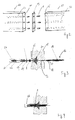
- FIG 3 an exploded view of the assembly as depicted in figure 4 is illustrated.
- the tendon which for the sake of illustration may be a Freysinnet-type tendon 16 comprises for example un-bonded seven wire strands 17 which are twisted together.
- the wire strands are twisted together in a grease-filled manner such that a suitable grease will fill out the small voids between the different strands in the twisted cable 17.
- the strands may be provided with a plastic seating 18 and thereafter both the strands 17 and the sheeting 18 are fitted inside a duct 19, e.g. made from PVC or other suitable material.
- This cable is arranged inside a duct 12 provided in a concrete panel 11.
- a mono-anchor plate 20 is cast into the panel in order to create the tendon's anchorage.
- the anchorage comprises a number of wedges 21, 22, a coupler 23 and a gasket/washer 24.
- the sealing device 1 is arranged between the washer 24 and the cast-in anchor-block 20 in such a way that part of the sealing device 1 projects into the aperture 25.
- the washer 24 will force the sealing device 1 into the anchor block 20 and at the same time deform the sealing element slightly so that the sealing device will completely fill out the space between the tendon 16 and the mono-block 20 as illustrated with reference to figure 4 .
- the tendon stressing means (not illustrated) may be released and an end cap 26 applied in order to protect the anchorage of the tendons in the structure.
- an end cap 26 applied in order to protect the anchorage of the tendons in the structure.
- the two concrete elements 10,11 to be sealingly assembled are fitted with the post-tension tendon 30.
- the tendon comprises a PVC sheating 31.
- the sheating has been trimmed to be flush with the end surface 14 of the panel 10, whereas the sheating 31 projects a distance out from the opposite end surface 15.
- a sealing device 1 according to the invention is fitted around the projecting sheating 31. As the tension in the tendon is increased and the two panels 10,11 forced together, the sealing device 1 will engage the duct opening and the sheating on the opposite side, and thereby create a completely liquid-tight sealing of the ducts 12.
Landscapes
- Engineering & Computer Science (AREA)
- Architecture (AREA)
- Civil Engineering (AREA)
- Structural Engineering (AREA)
- Pipe Accessories (AREA)
- Building Environments (AREA)
Applications Claiming Priority (1)
| Application Number | Priority Date | Filing Date | Title |
|---|---|---|---|
| DKPA200700559 | 2007-04-17 |
Publications (2)
| Publication Number | Publication Date |
|---|---|
| EP1983125A2 true EP1983125A2 (de) | 2008-10-22 |
| EP1983125A3 EP1983125A3 (de) | 2015-09-02 |
Family
ID=39471804
Family Applications (1)
| Application Number | Title | Priority Date | Filing Date |
|---|---|---|---|
| EP08154694.7A Withdrawn EP1983125A3 (de) | 2007-04-17 | 2008-04-17 | Dichtungsvorrichtung |
Country Status (1)
| Country | Link |
|---|---|
| EP (1) | EP1983125A3 (de) |
Cited By (2)
| Publication number | Priority date | Publication date | Assignee | Title |
|---|---|---|---|---|
| CN109881573A (zh) * | 2019-04-01 | 2019-06-14 | 西南交通大学 | 一种装配式空心板桥构造 |
| DE102024112814A1 (de) * | 2024-05-07 | 2025-11-13 | Karlsruher Institut für Technologie, Körperschaft des öffentlichen Rechts | Bauteil mit zwei über mindestens eine Verbindung miteinander verbundenen Komponenten |
Family Cites Families (6)
| Publication number | Priority date | Publication date | Assignee | Title |
|---|---|---|---|---|
| DE1609675A1 (de) * | 1966-10-05 | 1970-04-16 | Holzmann Philipp Ag | Korrosionsschutzvorrichtung fuer Spannglieder in Spannbetonbauteilen |
| DE3224702C2 (de) * | 1982-07-02 | 1986-01-16 | Dyckerhoff & Widmann AG, 8000 München | Vorrichtung zum Verankern und Koppeln eines Bündelspannglieds für Spannbeton |
| DE3824107A1 (de) * | 1988-06-27 | 1990-03-15 | Werner Zapf | Aus mehreren stahlbetonfertigteilen zusammengefuegter baukoerper in einer spannbetonbauweise |
| US5839235A (en) * | 1997-08-20 | 1998-11-24 | Sorkin; Felix L. | Corrosion protection tube for a post-tension anchor system |
| EP1046759A1 (de) * | 1999-04-19 | 2000-10-25 | BBR Systems Ltd. | Verankerung für Litzen in Beton |
| CH696037A5 (fr) * | 2003-03-25 | 2006-11-30 | Freyssinet Int Stup | Dispositif pour raccorder bout à bout des premier et deuxième câbles. |
-
2008
- 2008-04-17 EP EP08154694.7A patent/EP1983125A3/de not_active Withdrawn
Cited By (2)
| Publication number | Priority date | Publication date | Assignee | Title |
|---|---|---|---|---|
| CN109881573A (zh) * | 2019-04-01 | 2019-06-14 | 西南交通大学 | 一种装配式空心板桥构造 |
| DE102024112814A1 (de) * | 2024-05-07 | 2025-11-13 | Karlsruher Institut für Technologie, Körperschaft des öffentlichen Rechts | Bauteil mit zwei über mindestens eine Verbindung miteinander verbundenen Komponenten |
Also Published As
| Publication number | Publication date |
|---|---|
| EP1983125A3 (de) | 2015-09-02 |
Similar Documents
| Publication | Publication Date | Title |
|---|---|---|
| US7424792B1 (en) | Positively retained cap for use on an encapsulated anchor of a post-tension anchor system | |
| US5755065A (en) | Method and apparatus for forming an anchorage of a post-tension system | |
| US6843031B1 (en) | Bonded monostrand post-tension system | |
| US6151850A (en) | Intermediate anchorage system utilizing splice chuck | |
| JP6684838B2 (ja) | プレストレス沈埋函構造及びその施工方法 | |
| CN102939420B (zh) | 密封装置 | |
| US9644369B2 (en) | Post-tension concrete leave out splicing system and method | |
| EP0512052A1 (de) | Ankersystem zum nachträglichen spannen. | |
| US11035122B1 (en) | Intermediate concrete anchor system with cap | |
| JPH0240813B2 (de) | ||
| US20210062941A1 (en) | Duct Coupler for Use with Ducts in a Wet Joint of Segmental Concrete Construction | |
| US5939003A (en) | Post-tensioning apparatus and method | |
| US7267375B1 (en) | Duct coupler apparatus | |
| US20160305140A1 (en) | Method and apparatus for repairing post-tensioned concrete | |
| JP5266584B2 (ja) | 防食pc鋼より線組付体、およびアンカー構造の構築方法 | |
| US20230125237A1 (en) | Intermediate anchor assembly | |
| US11781329B2 (en) | Sealing connector for post tensioned anchor system | |
| US7273238B1 (en) | Duct coupler apparatus with compressible seals | |
| EP1983125A2 (de) | Dichtungsvorrichtung | |
| US20200378121A1 (en) | Apparatus for repairing a tension member | |
| KR101010721B1 (ko) | 지중 송, 배전용 맨홀 | |
| JP5273663B2 (ja) | 防食pcストランドを用いたアンカー構造とその構築方法、および複合アンカー部材 | |
| US20190292785A1 (en) | Method for connecting precast segments tendon ducts and resulting structure | |
| KR20120019876A (ko) | 파형강판용 수밀결합구 | |
| US10731345B1 (en) | Coupling encapsulator for repairing post-tensioned concrete |
Legal Events
| Date | Code | Title | Description |
|---|---|---|---|
| PUAI | Public reference made under article 153(3) epc to a published international application that has entered the european phase |
Free format text: ORIGINAL CODE: 0009012 |
|
| AK | Designated contracting states |
Kind code of ref document: A2 Designated state(s): AT BE BG CH CY CZ DE DK EE ES FI FR GB GR HR HU IE IS IT LI LT LU LV MC MT NL NO PL PT RO SE SI SK TR |
|
| AX | Request for extension of the european patent |
Extension state: AL BA MK RS |
|
| RAP1 | Party data changed (applicant data changed or rights of an application transferred) |
Owner name: A-CONSULT HOLDING GROUP A/S |
|
| PUAL | Search report despatched |
Free format text: ORIGINAL CODE: 0009013 |
|
| AK | Designated contracting states |
Kind code of ref document: A3 Designated state(s): AT BE BG CH CY CZ DE DK EE ES FI FR GB GR HR HU IE IS IT LI LT LU LV MC MT NL NO PL PT RO SE SI SK TR |
|
| AX | Request for extension of the european patent |
Extension state: AL BA MK RS |
|
| RIC1 | Information provided on ipc code assigned before grant |
Ipc: E04C 5/12 20060101ALI20150728BHEP Ipc: E04C 5/10 20060101AFI20150728BHEP |
|
| AKY | No designation fees paid | ||
| AXX | Extension fees paid |
Extension state: MK Extension state: BA Extension state: RS Extension state: AL |
|
| REG | Reference to a national code |
Ref country code: DE Ref legal event code: R108 |
|
| STAA | Information on the status of an ep patent application or granted ep patent |
Free format text: STATUS: THE APPLICATION IS DEEMED TO BE WITHDRAWN |
|
| 18D | Application deemed to be withdrawn |
Effective date: 20160303 |