EP1982951A1 - Ensemble distributeur de boissons - Google Patents
Ensemble distributeur de boissons Download PDFInfo
- Publication number
- EP1982951A1 EP1982951A1 EP07388021A EP07388021A EP1982951A1 EP 1982951 A1 EP1982951 A1 EP 1982951A1 EP 07388021 A EP07388021 A EP 07388021A EP 07388021 A EP07388021 A EP 07388021A EP 1982951 A1 EP1982951 A1 EP 1982951A1
- Authority
- EP
- European Patent Office
- Prior art keywords
- dispensing
- valve element
- dispensing line
- beverage dispensing
- beverage
- Prior art date
- Legal status (The legal status is an assumption and is not a legal conclusion. Google has not performed a legal analysis and makes no representation as to the accuracy of the status listed.)
- Withdrawn
Links
Images


Classifications
-
- B—PERFORMING OPERATIONS; TRANSPORTING
- B67—OPENING, CLOSING OR CLEANING BOTTLES, JARS OR SIMILAR CONTAINERS; LIQUID HANDLING
- B67D—DISPENSING, DELIVERING OR TRANSFERRING LIQUIDS, NOT OTHERWISE PROVIDED FOR
- B67D1/00—Apparatus or devices for dispensing beverages on draught
- B67D1/04—Apparatus utilising compressed air or other gas acting directly or indirectly on beverages in storage containers
- B67D1/0412—Apparatus utilising compressed air or other gas acting directly or indirectly on beverages in storage containers the whole dispensing unit being fixed to the container
-
- B—PERFORMING OPERATIONS; TRANSPORTING
- B67—OPENING, CLOSING OR CLEANING BOTTLES, JARS OR SIMILAR CONTAINERS; LIQUID HANDLING
- B67D—DISPENSING, DELIVERING OR TRANSFERRING LIQUIDS, NOT OTHERWISE PROVIDED FOR
- B67D1/00—Apparatus or devices for dispensing beverages on draught
- B67D1/08—Details
- B67D1/12—Flow or pressure control devices or systems, e.g. valves, gas pressure control, level control in storage containers
- B67D1/1277—Flow control valves
-
- B—PERFORMING OPERATIONS; TRANSPORTING
- B67—OPENING, CLOSING OR CLEANING BOTTLES, JARS OR SIMILAR CONTAINERS; LIQUID HANDLING
- B67D—DISPENSING, DELIVERING OR TRANSFERRING LIQUIDS, NOT OTHERWISE PROVIDED FOR
- B67D2210/00—Indexing scheme relating to aspects and details of apparatus or devices for dispensing beverages on draught or for controlling flow of liquids under gravity from storage containers for dispensing purposes
- B67D2210/00028—Constructional details
- B67D2210/00047—Piping
- B67D2210/00049—Pipes
Definitions
- This invention relates to a beverage dispensing assembly to be used in combination with a tapping cock.
- DraughtMaster TM a professional draught beer system
- DraughtMaster TM comprising a beverage dispensing system and a chill chamber in which the keg or pack containing carbonate beer is received.
- the keg or pack containing carbonated beer comprises a flexible bottle or bag, which is exposed to an elevated pressure from the outside for dispensing the beer.
- the flexible bottle or bag is connected through a dispensing line to a shut-off valve, which is guided through a channel of the beverage dispensing system and is received within and operated by means of a tap handle of a tapping cock for operating the shut-off valve between an open and a closed position.
- the dispensing line and shut-off valve Prior to operation, the dispensing line and shut-off valve are to be mounted properly within the tapping cock of the beverage dispensing system. This, however, may be a complicated process since the dispensing line with the shut-off valve are to be pushed through the inside of the tapping cock. The dispensing line and the valve must be correctly and securely connected and fixed to one another and to the tap handle of the tapping cock.
- the beverage dispensing assembly constitutes a component of a draught beer system also including the dispensing line and as is well known in the art, a refrigerator system for cooling the beer contained within the keg or pack and additional components well known in the art per se. It is to be realised that the beverage dispensing assembly may be used in connection with a draught beer system similar to the commercially available DraughtMaster TM system produced and sold by the applicant company, in which a collapsible keg or bag is used, however, the beverage dispensing assembly according to the present invention may alternatively be used in combination with a conventional draught beer system, in which non-carbonised beer containing metal kegs and carbonising pressurised containers are used.
- the separate valve element apart from fulfilling requirements as to compatibility with the tap handle of the DraughtMaster TM system or the top handle of a similar system fulfils specific operational requirements in particular to provide a safe closing-off and safe opening of the shut-off valve when operated by the tap handle, and, consequently, the shut-off valve must not allow the beer to leak or drip from the dispensing line, and, in addition, the shut-off valve should prevent that the beer is frothing when the shut-off valve is opened by operating the tap handle.
- the dispensing line is mounted to the valve element, the controlled dispensing of a drink can be obtained. Especially if the drink is a carbonated drink, such as beer, undesired frothing is counteracted.
- the flow characteristics through the dispensing line according to the invention can be adjusted by sizing the fluid outlet dimension of the dispensing line and the dimensions of the valve element.
- the dispensing line and the valve element according to the present invention are particularly suitable for dispensing beverages, e.g. wine, coffee, milk or carbonated drink, such as beer.
- beverages e.g. wine, coffee, milk or carbonated drink, such as beer.
- the dispensing line is by itself automatically closed when placing the pack containing carbonated drink in the dispenser device, so that leakage of carbonated drink is prevented.
- the dispensing line of the beverage dispensing assembly according to the present invention is likewise also automatically closed when the empty pack is removed from the dispenser device and leakage of any beer present in the flexible dispensing line is prevented.
- the dispensing line can be of rigid construction, but can also be telescopic or at least partially of a flexible construction. The latter is preferred since this facilitates the positioning and the fixating of the dispensing line and the valve element in the tapping cock.
- the dispensing line can be permanently connected to the container containing a carbonated drink.
- the dispensing line may be a separate component which is provided with a coupling for detachable connection to the keg or pack. Consequently, the dispensing line may constitute a lightweight, simple construction, which can easily be accommodated, stored and transported in or together with the keg or the pack.
- the dispensing line may be accommodated in a coiled state on top of or beneath the base of the keg or pack containing the beverage.
- An operating element of the tapping cock preferably comprises components or elements to which the dispensing line and the valve element are connected.
- the valve element may be provided with corresponding coupling components or elements and may be operated by e.g. moving it or by applying a force to it.
- valve element or the dispensing line is opened and closed by operating the handle of the tapping cock.
- a beverage dispensing assembly to be used in combination with a tapping cock including a tapping cock housing and a tap handle operable between a first position and a second position, said first position constituting a non-beverage dispensing position and said second position constituting a beverage dispensing position, said beverage dispensing assembly comprising two separate elements:
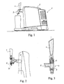
- Fig. 1 illustrates a prior art drink dispenser assembly.
- the dispenser device assembly 1 comprises a housing 2 including a chill chamber in which a keg or pack, not shown in the drawings, containing carbonated beer is placed.
- the keg or pack containing carbonated beer comprises a flexible bottle or bag containing the carbonated beer.
- the flexible bottle or bag is connected through a dispensing line to a shut-off valve at the dispensing end of the dispensing ling.
- a dispensing head 3 acting as a tapping cock and a tap handle 4
- the shut-off valve is operated between an open position and a closed position.
- Figs. 2 and 3 illustrate the tap handle 4 and a dispensing line 6 with a shut-off valve 8.
- the dispensing line 6 is positioned in the interior of the dispensing head of the tapping cock and the shut-off valve 8 is biased by a spring 7 to its closed position. Operation of the tap handle 4 away from the position shown causes compression of the biasing spring 7, which in turn moves the shut-off valve 8 to its open position.
- Fig. 4a, 4b, 4c , 4d, 4e and 4f illustrate schematic views of a first preferred embodiment of a beverage dispensing assembly according to the present invention.
- the beverage dispensing assembly designated the reference numeral 15 in its entirely basically comprises two separate elements: a dispensing line 10 and a valve element 20 as shown in figures 4b - 4g .
- Fig. 4a illustrates the dispensing line 10 defining a dispensing end 11 and an opposite keg connection end, not shown in the drawing.
- a sealing membrane 12 is provided acting as a prior to use sealing closure which is, as will be described below, opened or ruptured when assembling the dispensing line 10 to the valve element 20.
- the dispensing line 10 is provided with a coupling element 14 integrally cast with the sealing membrane and defining at the dispensing end 11 a circumferential protrusion 13.
- the coupling element 14 constitutes a circular skirt circumferentially encircling the dispensing end 11.
- the coupling element 14 is at its inner cylindrical surface provided with a circumferential bead designated the reference numeral 17 allowing the coupling element to co-operate with a corresponding circumferential recess of the valve element 20 as will be described below.
- the coupling element 14 is provided with an outer circumferential flange 18 serving to co-operate with a sleeve 40 of the tapping cock 30 of the dispensing handle 34 shown in Fig. 4g .
- Fig. 4b the dispensing line 10 is shown together with the valve element 20 in a position ready for connecting the dispensing line 10 to the valve element 20.
- the valve element 20 is basically composed of two parts, a bottom nozzle defining part 22 and a top connector part 24 serving to connect the valve element 20 to the coupling element 14 of the dispensing line 10.
- the top part 24 is at its upper end provided with an outer circumferential recess 26 serving to engage with and arrest with the inwardly protruding bead 17 of the coupling element 14.
- Fig. 4c the dispensing line 10 and the valve element 20 are in a pre-arresting position as the inwardly protruding bead 17 of the coupling element 14 has not reached its interlocking and arresting co-operation with the circumferential recess 26 of the top part 24 of the valve element 20.
- an inwardly sloping surface 28 is defined serving to catch the circumferential protrusion 13 and to rupture the membrane 12 as the coupling element 14 is further advanced towards the top part 24 of the valve element 20.
- the membrane 12 is initially in a biased configuration allowing the membrane 12, after the membrane has been ruptured, to be retracted from the dispensing end 11 of the dispensing line 10 and to conceal the ruptured membrane 12 between the outer surface of the dispensing line 10 and the inner wall of the top part 24 of the valve element 20, as is illustrated in Fig. 4d .
- valve element 20 In the process of interconnecting the coupling element 14 to the valve element 20, the valve element 20 is in a non-sealed or non-closed position as a pressure equalisation channel is provided and established by a through-going passage defined by a wall 29 which passage is eventually blocked as the dispensing line 10 is permanently fixated to the valve element 20, as is illustrated in Fig. 4d .
- a closure stem 23 is provided within the nozzle part 22 of the valve element 20, serving to co-operate with a similarly configurated inwardly sloping and mating surface 27 of the top part 24 of the valve element 20.
- valve is closed or sealed off as the closure stem 23 is caused to seal against the inner sloping surface and mating surface 27 of the top part 24 of the valve element 20. It is to be realised that the shifting of the valve element 20 between the open position shown in Fig. 4e and the closed position shown in Fig. 4f is established by shifting the top part 24 of the valve element 20 relative to the nozzle part 22 of the valve element 20 between an extracted position shown in Fig.
- the tapping cock 30 is shown comprising a tapping cock housing 32 defining a right angular bend in which the dispensing line 10 is received.
- the tapping cock 30 further comprises a handle 34 extending upwardly from the tapping cock housing 32 and is biased to two alternative positions by means of a biasing spring 36 to a first position shown in Fig. 4g in which the handle 34 is in an upright position in which the beverage dispensing assembly is closed and a second position in which the handle 34 is turned to the right or lowered as a conventional tap handle of a beverage dispensing system for opening the beverage dispensing assembly for causing the dispensing of beverage from the dispensing line 10.
- the handle 34 co-operates with a stem 38 acting on a sleeve 40 which catches with the outer circumferential flange 18 of the coupling element 14 for causing the coupling element 14 and the top part 24 of the valve element 20 to be raised to the position shown in Fig. 4e as the handle 34 is lowered from the upward position shown in Fig. 4g to the above described second position turned to the right as the nozzle part 22 of the valve element 20 is arrested relative to the tapping cock house 32 by means of a circumferential flange 42 of the housing 32 catching into a circumferential groove 19 of the nozzle part 22 of the valve element 20.
- the sleeve 22 causes the coupling element 14 to push the top part 24 of the valve element 20 into the closed position shown in Fig. 4f .
- the opening and closing operation of the handle 34 is also used for interconnecting the dispensing line 10 and the valve element 20 as initially, the valve element 20 is positioned in the lowermost end of the right angular bend tapping cock house 32 and fixated by the circumferential flange 42 described above, catching in the groove 19 and at the same time, the dispensing line 10 is introduced through the tapping cock housing 32 from the left hand side of the tapping cock housing 32 and positioned in engagement with the sleeve 40 as the sleeve is raised by lowering the handle 34 from the position shown in Fig. 4g to the above described position in which the handle is turned to the right.
- the dispensing line 10 and the valve element 20 are fitted together as is illustrated in Fig. 4c while the handle 34 is in the above described lowered position and, the handle 34 is then raised to its upright position shown in Fig. 4g causing the dispensing line 10 to be permanently connected to the valve element 20 as is illustrated in Fig. 4 .
- a second embodiment of a beverage dispensing assembly is shown differing from the above first described and first embodiment in that the coupling element 14' of the dispensing line 10 is of a somewhat simplified structure as the inwardly protruding bead 17 and the outwardly protruding flange 18 are omitted, and similarly, the top part 24' of the valve element 20' fails to include a circumferential recess similar to the recess 26 described above.
- the valve element 20' basically differs from the above described first embodiment of the valve element 20 shown in Figs. 4a-4f in that the top part 24' of the valve element 20' shown in Figs.
- valve element 20' shown in Fig. 5c is initially in its closed position as the cam surface 21 is co-operating with the cam surface 25b of the nozzle part 22 and the connector element 14' of the dispensing line 10 is simply resting on top of the top part 24' of the valve element 20'.
- the second embodiment of the beverage dispensing assembly shown in Fig. 5a-5e and further the additional embodiments of the beverage dispensing assembly to be described below, are intended to be used in the same tapping cock 30 as shown in Figs. 4g , and no detailed or separate description of the tapping cock is consequently presented in relation to the second and the additional embodiments of the beverage dispensing assembly.
- the tap handle 34 of the tapping cock 30 is in its upright position shown in Fig. 4g and the connecting element 14 is press-fitted into contact with the upper end of the top part 24' of the valve element 20' as illustrated in Fig. 4d as the handle 34 is turned to the right raising the sleeve 40, and consequently raising the top part 24' of the valve element 20' relative to the nozzle part 22 of the valve element 20'.
- the process of connecting the dispensing line 10 of the second embodiment to the valve element 20' shown in Figs. 5a-5e is finalised by shifting the handle of the tapping cock 30 to the upright position shown in Fig. 4g , and consequently closing the valve element 20' as is illustrated in Fig. 5e
- a third embodiment of the beverage dispensing assembly according to the present invention is shown differing from the above-described first and second embodiments in that the sealing membrane 12 is omitted and substituted by a sealing plug 12" which is positioned in a sealing recess at the outermost end of the coupling element 14" shown in Fig. 6a .
- a seat 13 is established to which the plug 12" is shifted as the dispensing line 10 is connected to the valve element 20" for opening the dispensing line as will be described below with reference to Figs. 6b-6g .
- the dispensing line further differs from the above-described first and second embodiments in that the inwardly protruding bead 17 shown in Figs. 4a-4f is substituted by an outwardly protruding bead 17" serving to co-operate with a similarly configurated inner recess 26" of the top part 24" of the valve element 20".
- the top part 24" of the valve element 20" is provided with an outwardly protruding flange 18" serving to catch with the vertically raisable sleeve 40 of the dispensing cock 30 shown in Fig. 4g .
- the dispensing line 10 is to be introduced into co-operating and fitting engagement with the top part 24" of the valve element 20" and in Fig. 6c , the valve element 20" and the dispensing line 10 are received within the tapping cock 30 shown in Fig. 4g and then the handle 34 of the tapping cock 30 is lowered from the position shown in Fig. 4g to the position described above turned to the right forcing the sleeve 42 to be raised and shifting the top part 24" of the valve element 20" from the position shown in Fig. 6c to a position shown in Fig.
- the handle of the tap cock 30 is raised to its vertical position shown in Fig. 4g causing the top part 24" of the valve element 20" to be forced downwardly causing the cam surface 21 to shift from its engagement with the cam surface 25a of the top part 24" to engagement with the cam surface 25b of the top part 24".
- the uppermost end of the closing stem 23" contacts the sealing plug 12" and shifts the plug from its original position to its retracted position in the above-described seat 13 as the lowermost end of the connecting element 14" are slightly separated due to contact with the conical configuration of the top surface of the stem 23".
- the sealing plug 12" has been shifted to its retracted position shown in Fig.
- a passage bypassing the plug is established by the seat 13 and, as is illustrated in Fig. 6f , the raising of the top part 24" of the valve element 20" allows the beverage to pass the retracted sealing plug 12" and to be expelled past the sealing stem 23".
- the valve element 20" is again shifted to the closed position shown in Fig. 6g in which the lowermost end of the connecting element 14" seals against the conical top surface of the sealing stem 23" closing off the passage through the valve element 20".
- a fourth embodiment of the beverage dispensing assembly including like the above-described third embodiment, a sealing plug 12"'.
- the sealing plug 12'" of the fourth embodiment shown in Figs. 7a-7d serve as a sealing plug in the assembled beverage dispensing assembly. Consequently, the connecting element 14''' of the fourth embodiment of the beverage dispensing assembly shown in Figs. 7a-7d differs from the above-described third embodiment shown in Figs. 6a-6g in that the retracted positioning seat 13 is omitted.
- the top part 24''' of the valve element 20''' includes a simple blunt stem element 23"' and a bottom circumferential receptor recess 28''' into which the outermost end of the connecting element 14"' is to be arrested as is illustrated in Fig. 7c causing the sealing plug 12''' to be disengaged from its original sealing engagement at the lowermost end of the dispensing line 10 and allowing the sealing plug 12''' to act as a sealing plug to be shifted between a free position shown in Fig. 7c resting on the blunt stem part 23"' and into engagement with an inner sealing surface 27''' of the connecting element 14''' shown in Fig. 7d .
- the dispensing line 10 is inserted into the top part 24''' of the valve element 20''' as the tap handle 34 of the tapping cock 30 shown in Fig. 4g is initially in its upright or closed position.
- the tap handle 34 By turning the tap handle 34 from its upright or closed position shown in Fig.
- the sleeve 40 catching with the upwardly protruding bead 18''' of the top part 24''' of the valve element 20''' causes the top part 24"' to be raised and to press the connecting element 14''' into sealing engagement within the top part 24"' of the valve element 20"' as the outwardly protruding bead 17'' of the connecting element 14''' is caught and fixated relative to the inner circumferential recess 26" of the top part 24''' as is illustrated in Fig. 7c .
- the sealing plug 12''' is disengaged from its sealing engagement with the outermost end of the connecting element 14''' and is allowed to rest on top of the blunt sealing stem 23''' and allowing the beverage to pass freely out from the dispensing line 10 and past the sealing plug 12"'.
- the cam surface 21 of the nozzle part 22 of the valve element 20"' is disengaged from its engagement with the cam surface 25a of the top part 24''' of the valve element 20''' and forced into engagement with the cam surface 25b and at the same time the blunt stem part 23''' forces the sealing plug 12''' into sealing engagement with the inner sealing surface 27''' of the connecting element 14''' sealing off the beverage dispensing line and interrupting the dispensing of beverage through the dispensing line 10.
- a fifth embodiment of the beverage dispensing assembly comprising a separate elastomeric valve element 20 iv .
- the elastomeric valve element 20 iv is initially cast in an elongated cylindrical configuration as is illustrated in Fig. 8a , comprising a bottom valve part 22 iv and a top valve part 24 iv .
- a central protrusion 50 is provided establishing the recess 19 for cooperating with the flange 42 of the tapping cock 30 shown in Fig. 4g .
- a further protrusion 56 is provided serving as the lowermost body part of the final valve element shown in Fig. 8c .
- the bottom part 22 iv of the elastomeric valve element 20 iv is provided with an inwardly protruded flange 52, and at the upper part of the elastomeric valve element 20 iv , a cylindrical part protrudes from an inwardly extending flange 54.
- the outwardly protruding bead 18" extends.
- a first step of eversion of the elastomeric body shown in Fig. 8a into the final elastomeric valve element shown in Fig. 8c is performed as the upper cylindrical part 24 iv of the elastomeric valve element 20 iv is everted into an inwardly sloping conical surface 58.
- the bottom part 22 iv of the valve element 20 iv is everted from its original configuration shown in Figs. 8a and 8b into the configuration shown in Fig. 8c in which the flange 52 is everted and caused to catch behind the inwardly protruding flange 54 arresting the inverted bottom part 22 iv within the interior of the valve element 20 iv
- the central part of the elastomeric body located between the protrusion 50 and the inwardly protruding flange 54 is compressed as is illustrated in Fig. 8c providing a bellows-shaped biasing element 60.
- the final elastomeric valve element 20 iv shown in Fig. 8c is, like the above-described first, second, third and fourth embodiments of the beverage dispensing assembly intended to be assembled to and integrally connected to a free of the dispensing line 10 which connection is simply accomplished by introducing the dispensing line 10 into the interior of the valve element 20 iv as is illustrated in Fig. 8c and by operating the handle 34 of the tapping cock 30 shown in Fig. 4g , as the bellows-shaped biasing element 60 is stretched into the position shown in Fig. 8e , allowing the dispensing line 10 to be fully introduced into the interior of the valve element and at the same time opening the passage through the valve element.
- the bellows-shaped biasing element 60 of the elastomeric valve element 20 iv causes the shifting of the valve element 20 iv between an open position shown in Fig. 8g to a closed position shown in Fig. 8f after the movement of the tap handle 34 from the lower position not shown in Fig. 4g to the raised position shown in Fig. 4g .
- a sixth embodiment of the beverage dispensing assembly according the present invention is shown differing from the above-described assemblies in that the assembly is a so-called pinching-off assembly in which the outermost end of the dispensing line 10' constitutes a pinching-off valve element.
- the tapping cock 30' is shown comprising its handle 34' and an eccentric pinching-off body 40' which is journalled on a central axis 42 together with the tap handle 34'.
- the eccentric body 40' is rotated together with the tap handle 34' and is released from its pinching-off or sealing-off position shown in Fig. 9a to a beverage dispensing position as the tap handle 34' is lowered to a horizontal position by rotating the handle to the left to a position not shown in the drawings.
- a detail of the dispensing line 10' is shown together with a detail of a plug removable assembly of the beverage dispensing system.
- the dispensing line 10' is closed or sealed off by means of a plug 12 iv which is removed prior to use by means of a plug removal arm.
- the plug removal arm is designated the reference numeral 50 and is journalled on a rotational axis 52 allowing the plug removal arm to be pivoted rearwardly as is illustrated in Figs. 9c and 9d .
- the plug removal arm 50 is positioned in contact with the sealing-off plug 12 iv as is illustrated in Fig.
- a coupling stem 54' is operated manually causing a clutch of the plug removal arm 50 to engage within a recess at the outer free end of the plug 12 iv and locking the plug removal arm 50 to the plug 12 iv .
- the plug removal arm 50 is arrested relative to the eccentric body 40' by means of a pin 44' which is disengaged from its connection to the plug removal arm 50 as the clutch 54 is operated allowing the pin 44' to be freely disconnected from the plug removal arm 50.
- the plug removal arm is then pivoted downwardly causing the plug 12 iv to be disengaged from the dispensing end of the dispensing line 10' and allowing the tap handle 34' to be turned to the left for dispensing beverage from the dispensing end 11' of the dispensing line 10'.
- Fig. 9c the plug 12 iv is shown disengaged from the dispensing line 10' and Fig. 9d illustrates a detail of the disengagement of the plug 12 iv from the dispensing line 10'.
- Figs. 9b and 9d the details of the interlocking and catching elements preventing unintentional disengagement of the sealing plug 12 iv from the dispensing line 10' is also shown.
Landscapes
- Devices For Dispensing Beverages (AREA)
Priority Applications (4)
| Application Number | Priority Date | Filing Date | Title |
|---|---|---|---|
| EP07388021A EP1982951A1 (fr) | 2007-04-16 | 2007-04-16 | Ensemble distributeur de boissons |
| EP08758207A EP2137095A1 (fr) | 2007-04-16 | 2008-04-16 | Ensemble distributeur de boissons |
| PCT/DK2008/000140 WO2008125115A1 (fr) | 2007-04-16 | 2008-04-16 | Ensemble distributeur de boissons |
| EP11190154.2A EP2426081A3 (fr) | 2007-04-16 | 2008-04-16 | Ensemble distributeur de boissons |
Applications Claiming Priority (1)
| Application Number | Priority Date | Filing Date | Title |
|---|---|---|---|
| EP07388021A EP1982951A1 (fr) | 2007-04-16 | 2007-04-16 | Ensemble distributeur de boissons |
Publications (1)
| Publication Number | Publication Date |
|---|---|
| EP1982951A1 true EP1982951A1 (fr) | 2008-10-22 |
Family
ID=38470124
Family Applications (3)
| Application Number | Title | Priority Date | Filing Date |
|---|---|---|---|
| EP07388021A Withdrawn EP1982951A1 (fr) | 2007-04-16 | 2007-04-16 | Ensemble distributeur de boissons |
| EP08758207A Withdrawn EP2137095A1 (fr) | 2007-04-16 | 2008-04-16 | Ensemble distributeur de boissons |
| EP11190154.2A Withdrawn EP2426081A3 (fr) | 2007-04-16 | 2008-04-16 | Ensemble distributeur de boissons |
Family Applications After (2)
| Application Number | Title | Priority Date | Filing Date |
|---|---|---|---|
| EP08758207A Withdrawn EP2137095A1 (fr) | 2007-04-16 | 2008-04-16 | Ensemble distributeur de boissons |
| EP11190154.2A Withdrawn EP2426081A3 (fr) | 2007-04-16 | 2008-04-16 | Ensemble distributeur de boissons |
Country Status (2)
| Country | Link |
|---|---|
| EP (3) | EP1982951A1 (fr) |
| WO (1) | WO2008125115A1 (fr) |
Cited By (7)
| Publication number | Priority date | Publication date | Assignee | Title |
|---|---|---|---|---|
| EP2179961A1 (fr) * | 2008-10-22 | 2010-04-28 | Carlsberg Breweries A/S | Élément de soupape pour ensemble distributeur de boissons |
| EP2213614A1 (fr) | 2009-01-29 | 2010-08-04 | Carlsberg Breweries A/S | Élément de soupape pour ensemble distributeur de boissons |
| EP2241531A1 (fr) | 2009-04-15 | 2010-10-20 | Carlsberg Breweries A/S | Procédé et système pour pressuriser et distribuer des boissons carbonatées |
| WO2010119054A1 (fr) | 2009-04-15 | 2010-10-21 | Carlsberg Breweries A/S | Procédé et système pour la mise sous pression et la distribution de boissons gazeuses |
| WO2015177328A1 (fr) * | 2014-05-23 | 2015-11-26 | Carlsberg Breweries A/S | Ensemble de distribution de boisson ayant une valve souple |
| RU201531U1 (ru) * | 2020-07-16 | 2020-12-21 | Виталий Васильевич Шевченко | Устройство для розлива пенящихся и/или газированных напитков |
| US20220227617A1 (en) * | 2021-01-21 | 2022-07-21 | Lg Electronics Inc. | Liquid dispenser |
Citations (3)
| Publication number | Priority date | Publication date | Assignee | Title |
|---|---|---|---|---|
| EP1555240A2 (fr) * | 2000-05-31 | 2005-07-20 | Heineken Technical Services B.V. | Ensemble distributeur de boisson, récipient pour boisson et canalisation de distribution de boisson |
| WO2006029626A1 (fr) * | 2004-09-13 | 2006-03-23 | Micro Matic A/S | Distributeur d'un systeme de distribution |
| WO2007019850A2 (fr) * | 2005-08-12 | 2007-02-22 | Carlsberg Breweries A/S | Ensemble de distribution de boissons |
-
2007
- 2007-04-16 EP EP07388021A patent/EP1982951A1/fr not_active Withdrawn
-
2008
- 2008-04-16 WO PCT/DK2008/000140 patent/WO2008125115A1/fr not_active Ceased
- 2008-04-16 EP EP08758207A patent/EP2137095A1/fr not_active Withdrawn
- 2008-04-16 EP EP11190154.2A patent/EP2426081A3/fr not_active Withdrawn
Patent Citations (3)
| Publication number | Priority date | Publication date | Assignee | Title |
|---|---|---|---|---|
| EP1555240A2 (fr) * | 2000-05-31 | 2005-07-20 | Heineken Technical Services B.V. | Ensemble distributeur de boisson, récipient pour boisson et canalisation de distribution de boisson |
| WO2006029626A1 (fr) * | 2004-09-13 | 2006-03-23 | Micro Matic A/S | Distributeur d'un systeme de distribution |
| WO2007019850A2 (fr) * | 2005-08-12 | 2007-02-22 | Carlsberg Breweries A/S | Ensemble de distribution de boissons |
Cited By (20)
| Publication number | Priority date | Publication date | Assignee | Title |
|---|---|---|---|---|
| EP2179961A1 (fr) * | 2008-10-22 | 2010-04-28 | Carlsberg Breweries A/S | Élément de soupape pour ensemble distributeur de boissons |
| WO2010046391A1 (fr) * | 2008-10-22 | 2010-04-29 | Carlsberg Breweries A/S | Élément de vanne pour ensemble distributeur de boisson |
| EP2213614A1 (fr) | 2009-01-29 | 2010-08-04 | Carlsberg Breweries A/S | Élément de soupape pour ensemble distributeur de boissons |
| WO2010086275A1 (fr) * | 2009-01-29 | 2010-08-05 | Carlsberg Breweries A/S | Élément de vanne d'un ensemble de distribution de boisson |
| CN102361813A (zh) * | 2009-01-29 | 2012-02-22 | 嘉士伯酿酒有限公司 | 饮料分配组件的阀元件 |
| CN102361813B (zh) * | 2009-01-29 | 2013-09-04 | 嘉士伯酿酒有限公司 | 饮料分配组件的阀元件 |
| EA021558B1 (ru) * | 2009-01-29 | 2015-07-30 | Карлсберг Брюириз А/С | Узел раздачи напитка |
| EP2241531A1 (fr) | 2009-04-15 | 2010-10-20 | Carlsberg Breweries A/S | Procédé et système pour pressuriser et distribuer des boissons carbonatées |
| WO2010119054A1 (fr) | 2009-04-15 | 2010-10-21 | Carlsberg Breweries A/S | Procédé et système pour la mise sous pression et la distribution de boissons gazeuses |
| CN106458559A (zh) * | 2014-05-23 | 2017-02-22 | 嘉士伯酿酒有限公司 | 具有柔性阀的饮料分配组件 |
| WO2015177328A1 (fr) * | 2014-05-23 | 2015-11-26 | Carlsberg Breweries A/S | Ensemble de distribution de boisson ayant une valve souple |
| JP2017516723A (ja) * | 2014-05-23 | 2017-06-22 | カールスバーグ・ブルワリーズ・エー/エス | 可撓性バルブ付飲料分配アセンブリ |
| US9896323B2 (en) | 2014-05-23 | 2018-02-20 | Carlsberg Breweries A/S | Beverage dispensing assembly with flexible valve |
| EA031086B1 (ru) * | 2014-05-23 | 2018-11-30 | Карлсберг Брюириз А/С | Узел раздачи напитка с эластичным клапаном |
| CN106458559B (zh) * | 2014-05-23 | 2019-04-26 | 嘉士伯酿酒有限公司 | 具有柔性阀的饮料分配组件 |
| AU2015261814B2 (en) * | 2014-05-23 | 2019-11-21 | Carlsberg Breweries A/S | Beverage dispensing assembly with flexible valve |
| RU201531U1 (ru) * | 2020-07-16 | 2020-12-21 | Виталий Васильевич Шевченко | Устройство для розлива пенящихся и/или газированных напитков |
| US20220227617A1 (en) * | 2021-01-21 | 2022-07-21 | Lg Electronics Inc. | Liquid dispenser |
| US11780724B2 (en) * | 2021-01-21 | 2023-10-10 | Lg Electronics Inc. | Liquid dispenser |
| US12246962B2 (en) | 2021-01-21 | 2025-03-11 | Lg Electronics Inc. | Liquid dispenser |
Also Published As
| Publication number | Publication date |
|---|---|
| EP2426081A3 (fr) | 2014-08-27 |
| EP2426081A2 (fr) | 2012-03-07 |
| EP2137095A1 (fr) | 2009-12-30 |
| WO2008125115A1 (fr) | 2008-10-23 |
Similar Documents
| Publication | Publication Date | Title |
|---|---|---|
| EP1982951A1 (fr) | Ensemble distributeur de boissons | |
| RU2430010C2 (ru) | Емкость для напитка и узел в сборе из такой емкости и выдачного устройства | |
| DK2001791T3 (en) | BEVERAGES FOR BEVERAGES | |
| JPS63178988A (ja) | カプラ装置 | |
| EP2928814B1 (fr) | Ensemble de distribution de boisson et récipient destiné à être utilisé dans un ensemble de distribution de boisson | |
| US9815677B2 (en) | Dispensing line for a dispensing system | |
| US9434595B2 (en) | Keg connector | |
| CN113165859B (zh) | 用于通过包括分配阀的分配管来分配饮料的套件 | |
| WO2008044923A1 (fr) | Dispositif de distribution de fluide | |
| EP2179961A1 (fr) | Élément de soupape pour ensemble distributeur de boissons | |
| EP1789360B1 (fr) | Distributeur d'un systeme de distribution | |
| US12037234B2 (en) | Pressure vessel for use in a beverage dispensing assembly | |
| WO2004035412A1 (fr) | Ensemble bec verseur | |
| NL2009863C2 (en) | Beverage dispensing assembly and valve operating assembly therefore. | |
| HK1128674A (en) | Beverage container and assembly of such a container and a tapping device | |
| HK1211913B (en) | Beverage dispensing assembly and container for use in a beverage dispensing assembly | |
| AU2004205049A1 (en) | Keg filling and dispensing system with valve assembly fitted from exterior |
Legal Events
| Date | Code | Title | Description |
|---|---|---|---|
| PUAI | Public reference made under article 153(3) epc to a published international application that has entered the european phase |
Free format text: ORIGINAL CODE: 0009012 |
|
| AK | Designated contracting states |
Kind code of ref document: A1 Designated state(s): AT BE BG CH CY CZ DE DK EE ES FI FR GB GR HU IE IS IT LI LT LU LV MC MT NL PL PT RO SE SI SK TR |
|
| AX | Request for extension of the european patent |
Extension state: AL BA HR MK RS |
|
| AKX | Designation fees paid | ||
| REG | Reference to a national code |
Ref country code: DE Ref legal event code: 8566 |
|
| STAA | Information on the status of an ep patent application or granted ep patent |
Free format text: STATUS: THE APPLICATION IS DEEMED TO BE WITHDRAWN |
|
| 18D | Application deemed to be withdrawn |
Effective date: 20090423 |