EP1982912B1 - Positioniervorrichtung für eine Fahrradkomponente - Google Patents
Positioniervorrichtung für eine Fahrradkomponente Download PDFInfo
- Publication number
- EP1982912B1 EP1982912B1 EP07118381A EP07118381A EP1982912B1 EP 1982912 B1 EP1982912 B1 EP 1982912B1 EP 07118381 A EP07118381 A EP 07118381A EP 07118381 A EP07118381 A EP 07118381A EP 1982912 B1 EP1982912 B1 EP 1982912B1
- Authority
- EP
- European Patent Office
- Prior art keywords
- positioning
- moving direction
- positioning member
- input member
- contact
- Prior art date
- Legal status (The legal status is an assumption and is not a legal conclusion. Google has not performed a legal analysis and makes no representation as to the accuracy of the status listed.)
- Not-in-force
Links
- 230000004044 response Effects 0.000 claims description 25
- 230000000750 progressive effect Effects 0.000 claims description 16
- 230000007246 mechanism Effects 0.000 claims description 8
- 230000000284 resting effect Effects 0.000 claims description 8
- 230000009471 action Effects 0.000 description 3
- 238000004519 manufacturing process Methods 0.000 description 3
- 230000000717 retained effect Effects 0.000 description 3
- 238000004804 winding Methods 0.000 description 3
- 230000006835 compression Effects 0.000 description 2
- 238000007906 compression Methods 0.000 description 2
- 238000010276 construction Methods 0.000 description 2
- 239000003562 lightweight material Substances 0.000 description 2
- 230000002860 competitive effect Effects 0.000 description 1
- 230000009977 dual effect Effects 0.000 description 1
- 230000004048 modification Effects 0.000 description 1
- 238000012986 modification Methods 0.000 description 1
Images


Classifications
-
- B—PERFORMING OPERATIONS; TRANSPORTING
- B62—LAND VEHICLES FOR TRAVELLING OTHERWISE THAN ON RAILS
- B62M—RIDER PROPULSION OF WHEELED VEHICLES OR SLEDGES; POWERED PROPULSION OF SLEDGES OR SINGLE-TRACK CYCLES; TRANSMISSIONS SPECIALLY ADAPTED FOR SUCH VEHICLES
- B62M9/00—Transmissions characterised by use of an endless chain, belt, or the like
- B62M9/04—Transmissions characterised by use of an endless chain, belt, or the like of changeable ratio
- B62M9/06—Transmissions characterised by use of an endless chain, belt, or the like of changeable ratio using a single chain, belt, or the like
- B62M9/10—Transmissions characterised by use of an endless chain, belt, or the like of changeable ratio using a single chain, belt, or the like involving different-sized wheels, e.g. rear sprocket chain wheels selectively engaged by the chain, belt, or the like
- B62M9/12—Transmissions characterised by use of an endless chain, belt, or the like of changeable ratio using a single chain, belt, or the like involving different-sized wheels, e.g. rear sprocket chain wheels selectively engaged by the chain, belt, or the like the chain, belt, or the like being laterally shiftable, e.g. using a rear derailleur
- B62M9/121—Rear derailleurs
- B62M9/124—Mechanisms for shifting laterally
- B62M9/1244—Mechanisms for shifting laterally limiting or positioning the movement
-
- B—PERFORMING OPERATIONS; TRANSPORTING
- B62—LAND VEHICLES FOR TRAVELLING OTHERWISE THAN ON RAILS
- B62M—RIDER PROPULSION OF WHEELED VEHICLES OR SLEDGES; POWERED PROPULSION OF SLEDGES OR SINGLE-TRACK CYCLES; TRANSMISSIONS SPECIALLY ADAPTED FOR SUCH VEHICLES
- B62M9/00—Transmissions characterised by use of an endless chain, belt, or the like
- B62M9/04—Transmissions characterised by use of an endless chain, belt, or the like of changeable ratio
- B62M9/06—Transmissions characterised by use of an endless chain, belt, or the like of changeable ratio using a single chain, belt, or the like
- B62M9/10—Transmissions characterised by use of an endless chain, belt, or the like of changeable ratio using a single chain, belt, or the like involving different-sized wheels, e.g. rear sprocket chain wheels selectively engaged by the chain, belt, or the like
- B62M9/12—Transmissions characterised by use of an endless chain, belt, or the like of changeable ratio using a single chain, belt, or the like involving different-sized wheels, e.g. rear sprocket chain wheels selectively engaged by the chain, belt, or the like the chain, belt, or the like being laterally shiftable, e.g. using a rear derailleur
- B62M9/131—Front derailleurs
- B62M9/134—Mechanisms for shifting laterally
-
- Y—GENERAL TAGGING OF NEW TECHNOLOGICAL DEVELOPMENTS; GENERAL TAGGING OF CROSS-SECTIONAL TECHNOLOGIES SPANNING OVER SEVERAL SECTIONS OF THE IPC; TECHNICAL SUBJECTS COVERED BY FORMER USPC CROSS-REFERENCE ART COLLECTIONS [XRACs] AND DIGESTS
- Y10—TECHNICAL SUBJECTS COVERED BY FORMER USPC
- Y10T—TECHNICAL SUBJECTS COVERED BY FORMER US CLASSIFICATION
- Y10T74/00—Machine element or mechanism
- Y10T74/20—Control lever and linkage systems
- Y10T74/20396—Hand operated
- Y10T74/20402—Flexible transmitter [e.g., Bowden cable]
- Y10T74/2042—Flexible transmitter [e.g., Bowden cable] and hand operator
- Y10T74/20438—Single rotatable lever [e.g., for bicycle brake or derailleur]
-
- Y—GENERAL TAGGING OF NEW TECHNOLOGICAL DEVELOPMENTS; GENERAL TAGGING OF CROSS-SECTIONAL TECHNOLOGIES SPANNING OVER SEVERAL SECTIONS OF THE IPC; TECHNICAL SUBJECTS COVERED BY FORMER USPC CROSS-REFERENCE ART COLLECTIONS [XRACs] AND DIGESTS
- Y10—TECHNICAL SUBJECTS COVERED BY FORMER USPC
- Y10T—TECHNICAL SUBJECTS COVERED BY FORMER US CLASSIFICATION
- Y10T74/00—Machine element or mechanism
- Y10T74/20—Control lever and linkage systems
- Y10T74/20576—Elements
- Y10T74/20636—Detents
-
- Y—GENERAL TAGGING OF NEW TECHNOLOGICAL DEVELOPMENTS; GENERAL TAGGING OF CROSS-SECTIONAL TECHNOLOGIES SPANNING OVER SEVERAL SECTIONS OF THE IPC; TECHNICAL SUBJECTS COVERED BY FORMER USPC CROSS-REFERENCE ART COLLECTIONS [XRACs] AND DIGESTS
- Y10—TECHNICAL SUBJECTS COVERED BY FORMER USPC
- Y10T—TECHNICAL SUBJECTS COVERED BY FORMER US CLASSIFICATION
- Y10T74/00—Machine element or mechanism
- Y10T74/21—Elements
- Y10T74/2101—Cams
Definitions
- This invention generally relates to a bicycle component positioning device. More specifically, the present invention relates to a bicycle component positioning device for a bicycle component such as a derailleur or shifter, which has the same relatively easy action when moved in two opposite directions, yet is reliably retained.
- Bicycling is becoming an increasingly more popular form of recreation as well as a means of transportation. Moreover, bicycling has become a very popular competitive sport for both amateurs and professionals. Whether the bicycle is used for recreation, transportation or competition, the bicycle industry is constantly improving the various components of the bicycle such as derailleurs and shifters.
- a bicycle derailleur basically includes a base, a chain guide and a linkage coupled between the base and the chain guide to move the chain guide between various shift positions.
- the base is fixed to the bicycle frame.
- a spring is arranged to bias the chain guide in one lateral direction relative to the base.
- a control cable is used to move the chain guide against the biasing force of the spring when pulled, and to allow the bias force of the spring to move the chain guide in an opposite direction when the cable is released.
- a shifter is attached to the cable to selectively pull/release the cable to move the chain guide laterally back and forth respectively.
- the shifter typically utilizes one or more levers coupled to a winding member to selectively pull/release the cable for controlling a conventional derailleur.
- the winding member is retained in various shift positions by a retaining structure, friction or the like.
- some shifters further include an indexing mechanism with a plurality of positions corresponding to the number of shift positions.
- a sufficient retaining force must be applied to the winding member to prevent undesired movement of the chain guide of the derailleur due to the biasing force of the derailleur spring.
- a relatively strong retaining force must be provided, which can be relatively difficult to overcome when moving the lever(s).
- a bicycle component positioning device according to the preamble of claim 1 is known from EP 0 013 647 and FR 2 621 372 .
- One object of the present invention is to provide a bicycle component positioning device, which moves smoothly and reliably, yet is reliably retained in different positions.
- Another object of the present invention is to provide a bicycle component positioning device, which has a similar relatively light action when moved in opposite directions.
- Another object of the present invention is to provide a bicycle component positioning device, which is relatively simple and inexpensive to manufacture and/or assemble.
- the foregoing objects can basically be attained by providing a bicycle component positioning device according to claim 1, or a bicycle derailleur according to claim 11.
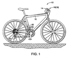
- a bicycle 10 is illustrated with a front shifting system and a rear shifting system coupled thereto in accordance with the present invention.
- the bicycle 10 includes, among other things, a frame 12 with a handle bar 14.
- the handle bar 14 has a right-hand shifter 16 mounted on a right-hand side and a left-hand shifter 18 mounted on a right-hand side.
- the frame 12 has a front derailleur 20 mounted to the seat tube and a rear derailleur 22 mounted a rear part of the chain stay.
- the right-hand shifter 16 is operatively coupled to one of the front derailleur 20 and the rear derailleur 22 by a first control cable 24, while the left hand shifter 18 is operatively coupled to the other of the front derailleur 20 and the rear derailleur 22 by a second control cable 26.
- the front derailleur 20 basically includes a base member 30, a movable member 32 supporting a chain guide 34, a linkage mechanism 36 and a positioning device 38.
- the front derailleur 20 is basically a conventional front derailleur, except for the addition of the positioning device 38 that is operated by one of the shifters 16 and 18.
- the base member 30 is attachable to the seat tube of the bicycle frame 12 in a conventional manner.
- the base member 30 is preferably a band clamp.
- the base member 30 can be attached to braze-on connections or mounted to the bottom bracket, if needed and/or desired.
- the movable member 32 is pivotally attached to the linkage mechanism 36 to support the chain guide 34 for laterally movement between an innermost or retracted position to an outermost or extended position with respect to the frame 12.
- the linkage mechanism 36 is arranged between the base member 30 and the movable member 32 to create a four-bar linkage with the base member 30 and the movable member 32 so that the chain guide 34 moves laterally relative to the base member 30.
- the chain guide 34 serves as an output member that is operatively coupled to the positioning device 38 to move in response to movement of the positioning device 38 due to operation of one of the shifters 16 and 18.
- positioning device 38 is illustrated as part of the front derailleur 20, it will be apparent to those skilled in the art that the positioning device 38 of the present invention can be adapted to the rear derailleur 22. Thus, the positioning device of the rear derailleur 22 will not be discussed and/illustrated in detail.
- the positioning device 38 is coupled to a link 36a of the linkage mechanism 36 for moving the linkage mechanism 36 between the innermost or retracted position to the outermost or extended position with respect to the frame 12.
- the positioning device 38 firmly positions the chain guide 34 in one of a plurality of operating positions.
- the positioning device 38 basically includes a housing or fixed structure 40, an input or operating member 42, a positioning member 44 and a plurality of biasing members 46, 48 and 50.
- the housing or fixed structure 40 is fixed with respect to the bicycle frame 12.
- the housing or fixed structure 40 can be fixed to the base member 30 or directly fixed to the bicycle frame 12.
- the precise structure of the housing or fixed structure 40 can take any necessary configuration to carry out the present invention.
- the housing or fixed structure 40 is preferably construction of a rigid and lightweight material.
- the fixed structure 40 houses the input member 42 and positioning member 44.
- the fixed structure 40 includes a plurality of positioning detents 40a that selectively engages the positioning member 44 to restrict movement of the positioning member 44 when the input member 42 is a rest position as explained below.
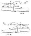
- the input member 42 is coupled to the fixed structure 40 to move back and forth along an operating plane in a first moving direction A and in a second moving direction B that is opposite to the first moving direction A. While the operating plane is illustrated as a flat plane, it will be apparent to those skilled in the art from this disclosure that the operating plane can be a curved plane. Thus, the term "operating plane" as used herein is not limited to a flat plane.
- the input member 42 is a cable operated member that is operated by one of the shifters 16 and 18 via one of the control cables 24 and 26 (e.g., derailleur operating members).
- the input member 42 includes a cable attachment structure 42a for operatively connecting one of the control cables 24 and 26 thereto.
- the control cables 24 and 26 are relative rigid cables in a longitudinal direction and relatively flexible in a transverse direction so that the control cables 24 and 26 can transmit a pushing force and a pull force between one of the shifters 16 and 18 and one of the derailleurs 20 and 22.
- the input member 42 can be operatively connected to one of the shifters 16 and 18 by a pair of cables such that one of the cables pulls the input member 42 in the first moving direction A and the other one of the cables pulls the input member 42 in the second moving direction B.
- the input member 42 can alternatively be operatively connected to a hydraulic or pneumatic operated shifter.
- the present invention can be used with a hydraulic actuating system or a pneumatic actuating system instead of a cable operated system.
- hydraulic or pneumatic lines constitute derailleur operating members that can operatively connect the input member 42 to one of the shifters 16 and 18.
- the input member 42 further includes a cam member with a first contact surface 42b, a second contact surface 42c, a third contact surface 42d and a fourth contact surface 42e.
- the first and second contact surfaces 42b and 42c are slanted surfaces that meet together at a point such that the first and second contact surfaces 42b and 42c are angled in opposite directions.
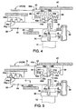
- the first contact surface 42b is configured and arranged relative to the positioning member 44 to initially move the positioning member 44 in a third (transverse) direction C, as seen in Figure 5 , when the input member 42 is moved in the first moving direction A, as seen in Figure 5 .
- the second contact surface 42c is configured and arranged relative to the positioning member 44 to initially move the positioning member 44 in the third (transverse) direction C, as seen in Figure 10 , when the input member 42 is moved in the second moving direction B, as seen in Figure 10 .
- the third and fourth contact surfaces 42d and 42e are parallel surfaces that face in opposite directions and extend from the first and second contact surfaces 42b and 42c, respectively.
- the third contact surface 42d is configured and arranged relative to the positioning member 44 to contact the positioning member 44 and then move the positioning member 44 in the first moving direction A after the positioning member 44 has been disengaged from the positioning detents 40a of the fixed structure 40 when the input member 42 is moved in the first moving direction A, as seen in Figures 5 and 6 .
- the fourth contact surface 42e is configured and arranged relative to the positioning member 44 to contact the positioning member 44 and then move the positioning member 44 in the second moving direction B after the positioning member 44 has been disengaged from the positioning detents 40a of the fixed structure 40 when the input member 42 is moved in the second moving direction B, as seen in Figures 10 and 11 .
- first and third contact surfaces 42b and 42d are arranged to contact the positioning member with the first contact surface 42b initially moving the positioning member 44 in the third direction C and the third contact surface subsequently moving the positioning member 44 in the first moving direction A in response to the first progressive movement of the input member 44 in the first moving direction A, as seen in Figures 4 to 6 .
- the positioning member 44 is moved in both of the first and third directions A and C by the first contact surface 42b, but the positioning member 44 is initially moved in the third direction C due to engagement of the positioning member 44 against the fixed structure 40 as explained below.
- the second and fourth contact surfaces 42c and 42e are arranged to contact the positioning member 44 with the second contact surface 42c initially moving the positioning member 44 in the third direction C and the fourth contact surface 42e subsequently moving the positioning member 44 in the second moving direction B in response to the second progressive movement of the input member-42 in the second moving direction B, as seen in Figures 9 to 11 .
- the positioning member 44 is moved in both of the second and third directions B and C by the second contact surface 42c, but the positioning member 44 is initially moved in the third direction C due to engagement of the positioning member 44 against the fixed structure 40 as explained below.
- the input member 42 is biased to a center rest position with respect to the positioning member 44 such that the input member 42 is movable in both of the first and second moving directions A and B from the rest position.
- the biasing members 46 and 48 are arranged between the input member 42 and the positioning member 44 to normally maintain the input member 42 in a rest position. While the biasing members 46 and 48 are illustrated as coiled compression springs, it will be apparent to those skilled in the art from this disclosure that other biasing arrangements can be utilized if needed and/or desired.
- the positioning member 44 is operatively coupled to the input member 42 to selectively move between a plurality of predetermined positions in response to movement of the input member 42.
- the positioning member 44 includes a movement restricting part 44a and an input transmitting part 44b.
- the movement restricting part 44a of the positioning member 44 selectively engages the positioning detents 40a to restrict movement of the positioning member 44 in both the first and second moving directions A and B when the input member 42 is in the rest position without a force being applied to the input member 42.
- the movement restricting part 44a of the positioning member 44 is normally biased into engagement with one of the positioning detents 40a by the biasing member 50.
- the input transmitting part 44b of the positioning member 44 cooperates with the contact surfaces 42b, 42c, 42d and 42e of the input member 42 and the fixed structure 40 so the positioning member 44 moves in response to movement of the input member 42.
- the input transmitting part 44b includes a first cam surface 44c, a second cam surface 44d, a first abutment surface 44e, a second abutment surface 44f and a pair of inclined surfaces 44g.
- the first cam surface 44c extends in the first moving direction A from a resting point.
- the second cam surface 44d extends in the second moving direction B from the resting point.
- the first abutment surface 44e faces in the second moving direction B.
- the second abutment surface 44f faces in the first moving direction A.
- the inclined surfaces 44g are formed on the free end of the movement restricting part 44a.
- the positioning member 44 is moved in both of the first and third directions A and C.
- the first contact surface 42b of the input member 42 contacts the first cam surface 44c of the positioning member 44 and one of the inclined surfaces 44g contacts the fixed structure 40 to initially move the positioning member 44 in the third direction C.
- the third contact surface 42d of the input member 42 subsequently contacts the first abutment surface 44e of the positioning member 44 to move in the first moving direction A in response to the first progressive movement of the input member 42 in the first moving direction A as seen in Figures 6 and 7 .
- the second contact surface 42c of the input member 42 contacts the second cam surface 44d of the positioning member 44 and one of the inclined surfaces 44g contacts the fixed structure 40 to initially move the positioning member 44 in the third direction C. Then the fourth contact surface 42e of the input member 42 subsequently contacts the second abutment surface 44f of the positioning member 44 to move in the second moving direction B in response to the second progressive movement of the input member 42 in the second moving direction B as seen in Figures 11 and 12 .
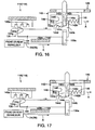
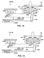
- Each of shifters 16 and 18 includes a positioning device 138 that is schematically illustrated in Figures 14 to 23 .
- the positioning device 138 is illustrated as moving in a flat plane for purposes of illustration. However, in the illustrated in embodiment, the positioning device 138 operates in a curved plane about a central pivot axis.
- the positioning device 138 is operatively coupled to one of the derailleurs 20 and 22 via one of the cables 24 and 26 for moving a linkage mechanism one of the derailleurs 20 and 22 between the innermost or retracted position to the outermost or extended position with respect to the frame 12.
- the positioning device 138 basically includes a housing or fixed structure 140, an input member or operating lever 142, a positioning member 144 and a plurality of biasing members 146, 148 and 150.
- the housing or fixed structure 140 is fixed with respect to the bicycle frame 12.
- the precise structure of the housing or fixed structure 140 can take any necessary configuration to carry out the present invention.
- the housing or fixed structure 140 is preferably construction of a rigid and lightweight material.
- the fixed structure 140 houses the input member 142 and positioning member 144.
- the fixed structure 140 includes a plurality of positioning detents 140a that selectively engages the positioning member 144 to restrict movement of the positioning member 144 when the input member 142 is a rest position as explained below.
- the input member 142 is coupled to the fixed structure 140 to move back and forth along a curved operating plane in a first curved direction A (first moving direction) and in a second curved direction B (second moving direction) that is opposite to the first curved direction A.
- the input member 142 is a rider operable member that extends outside of the fixed structure or housing 140.
- the input member 142 further includes a cam member with a first contact surface 142b, a second contact surface 142c, a third contact surface 142d and a fourth contact surface 142e.
- the first and second contact surfaces 142b and 142c are slanted surfaces that meet together at a point such that the first and second contact surfaces 142b and 142c are angled in opposite directions.
- the first contact surface 142b is configured and arranged relative to the positioning member 144 to initially move the positioning member 144 in a third (transverse) direction C, as seen in Figure 15 , when the input member 142 is moved in the first curved direction A, as seen in Figure 15 .
- the second contact surface 142c is configured and arranged relative to the positioning member 144 to initially move the positioning member 144 in the third (transverse) direction C, as seen in Figure 20 , when the input member 142 is moved in the second curved direction B, as seen in Figure 20 .
- the third and fourth contact surfaces 142d and 142e are parallel surfaces that face in opposite directions and extend from the first and second contact surfaces 142b and 142c, respectively.
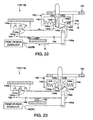
- the third contact surface 142d is configured and arranged relative to the positioning member 144 to contact the positioning member 144 and then move the positioning member 144 in the first curved direction A after the positioning member 144 has been disengaged from the positioning detents 140a of the fixed structure 140 when the input member 142 is moved in the first curved direction A, as seen in Figures 15 and 16 .
- the fourth contact surface 142e is configured and arranged relative to the positioning member 144 to contact the positioning member 144 and then move the positioning member 144 in the second curved direction B after the positioning member 144 has been disengaged from the positioning detents 140a of the fixed structure 140 when the input member 142 is moved in the second curved direction B, as seen in Figures 20 and 21 .
- the first and third contact surfaces 142b and 142d are arranged to contact the positioning member with the first contact surface 142b initially moving the positioning member 144 in the third direction C and the third contact surface subsequently moving the positioning member 144 in the first curved direction A in response to the first progressive movement of the input member 144 in the first curved direction A, as seen in Figures 14 to 16 .
- the positioning member 144 is moved in both of the first and third directions A and C by the first contact surface 142b, but the positioning member 144 is initially moved in the third direction C due to engagement of the positioning member 144 against the fixed structure 140 as explained below.
- the second and fourth contact surfaces 142c and 142e are arranged to contact the positioning member 144 with the second contact surface 142c initially moving the positioning member 144 in the third direction C and the fourth contact surface 142e subsequently moving the positioning member 144 in the second curved direction B in response to the second progressive movement of the input member 142 in the second curved direction B, as seen in Figures 19 to 21 .
- the positioning member 144 is moved in both of the second and third directions B and C by the second contact surface 142c, but the positioning member 144 is initially moved in the third direction C due to engagement of the positioning member 144 against the fixed structure 140 as explained below.
- the input member 142 is biased to a center rest position with respect to the positioning member 144 such that the input member 142 is movable in both of the first and second curved directions A and B from the rest position.
- the biasing members 146 and 148 are arranged between the input member 142 and the positioning member 144 to normally maintain the input member 142 in a rest position. While the biasing members 146 and 148 are illustrated as coiled compression springs, it will be apparent to those skilled in the art from this disclosure that other biasing arrangements can be utilized if needed and/or desired.
- the positioning member 144 is operatively coupled to the input member 142 to selectively move between a plurality of predetermined positions in response to movement of the input member 142.
- the positioning member 144 includes a movement restricting part 144a and an input transmitting part 144b.
- the movement restricting part 144a of the positioning member 144 selectively engages the positioning detents 140a to restrict movement of the positioning member 144 in both the first and second moving directions A and B when the input member 142 is in the rest position without a force being applied to the input member 142.
- the movement restricting part 144a of the positioning member 144 is normally biased into engagement with one of the positioning detents 140a by the biasing member 150.
- the input transmitting part 144b of the positioning member 144 cooperates with the contact surfaces 142b, 142c, 142d and 142e of the input member 142 and the fixed structure 140 so the positioning member 144 moves in response to movement of the input member 142.
- the input transmitting part 144b includes a first cam surface 144c, a second cam surface 144d, a first abutment surface 144e, a second abutment surface 144f and a pair of inclined surfaces 144g.
- the first cam surface 144c extends in the first curved direction A from a resting point.
- the second cam surface 144d extends in the second curved direction B from the resting point.
- the first abutment surface 144e faces in the second curved direction B.
- the second abutment surface 144f faces in the first curved direction A.
- the inclined surfaces 144g are formed on the free end of the movement restricting part 144a.
- the positioning member 144 is moved in both of the first and third directions A and C.
- the first contact surface 142b of the input member 142 contacts the first cam surface 144c of the positioning member 144 and one of the inclined surfaces 144g contacts the fixed structure 140 to initially move the positioning member 144 in the third direction C.
- the third contact surface 142d subsequently contacts the first abutment surface 144e of the positioning member 144 to move in the first curved direction A in response to the first progressive movement of the input member 142 in the first curved direction A as seen in Figures 16 and 17 .
- the second contact surface 142c of the input member 142 contacts the second cam surface 144d of the positioning member 144 and one of the inclined surfaces 144g contacts the fixed structure 140 to initially move the positioning member 144 in the third direction C. Then the fourth contact surface 142e subsequently contacts the second abutment surface 144f of the positioning member 144 to move in the second curved direction B in response to the second progressive movement of the input member 142 in the second curved direction B as seen in Figures 21 and 22 .
- each of the input members 42 and 142 could be constructed as two separate portions that are independently moveable in the first and second moving directions A and B, respectively.
- the term "input member” should be interpreted as including a single piece moveable in the first and second moving directions A and B as well as two or more separate pieces that are independently moveable.
- the following directional terms "forward, rearward, above, downward, vertical, horizontal, below and transverse" as well as any other similar directional terms refer to those directions of a bicycle equipped with the present invention.
Landscapes
- Engineering & Computer Science (AREA)
- Chemical & Material Sciences (AREA)
- Combustion & Propulsion (AREA)
- Transportation (AREA)
- Mechanical Engineering (AREA)
- Mechanical Control Devices (AREA)
- Transmission Devices (AREA)
Claims (12)
- Positioniervorrichtung für eine Fahrradkomponente (38, 138), umfassend:eine feststehende Struktur (40; 140),ein Eingangselement (42, 142), das relativ zu der feststehenden Struktur (40; 140) beweglich gekoppelt ist, wobei das Eingangselement (42, 142) eine erste Bewegungsrichtung (A) und eine zweite Bewegungsrichtung (B) aufweist, undein Positionierelement (44, 144), das mit dem Eingangselement (42, 142) funktionswirksam gekoppelt ist, um sich selektiv zwischen mehreren vorbestimmten Positionen zu bewegen,wobei das Eingangselement (42, 142) und das Positionierelement (44, 144) so gestaltet und relativ zueinander angeordnet sind, daß das Positionierelement (44, 144) in Reaktion auf eine Bewegung des Eingangselements (42, 142) sowohl in der ersten Bewegungsrichtung (A) als auch in der zweiten Bewegungsrichtung (B) durch das Eingangselement (42, 142) zunächst in einer dritten Richtung (C) bewegt wird, die von der ersten und der zweiten Bewegungsrichtung (A; B) verschieden ist,dadurch gekennzeichnet, daß das Positionierelement (44, 144) ein Eingangsübertragungsteil (44b, 144b) mit einer ersten Nockenfläche (44c, 144c), die sich von einem Ruhepunkt aus in der ersten Bewegungsrichtung (A) erstreckt, einer zweiten Nockenfläche (44d, 144d), die sich von dem Ruhepunkt aus in der zweiten Bewegungsrichtung (B) erstreckt, einer ersten Anlagefläche (44e, 144e), die der zweiten Bewegungsrichtung (B) zugewandt ist, und einer zweiten Anlagefläche (44f, 144f), die der ersten Bewegungsrichtung (A) zugewandt ist, aufweist,wobei das Eingangselement (42, 142) dazu eingerichtet ist, mit der ersten Nockenfläche (44c, 144c) des Positionierelements (44, 144) in Kontakt zu kommen, um zunächst das Positionierelement (44, 144) in der dritten Richtung (C) zu bewegen, und dann anschließend mit der ersten Anlagefläche (44e, 144e) des Positionierelements (44, 144) in Kontakt zu kommen, um es, in Reaktion auf die erste fortschreitende Bewegung des Eingangselements (42, 142) in der ersten Bewegungsrichtung (A), in der ersten Bewegungsrichtung (A) zu bewegen, undwobei das Eingangselement (42, 142) ferner dazu eingerichtet ist, mit der zweiten Nockenfläche (44d, 144d) des Positionierelements (44, 144) in Kontakt zu kommen, um zunächst das Positionierelement (44, 144) in der dritten Richtung (C) zu bewegen, und dann anschließend mit der zweiten Anlagefläche (44f, 144f) des Positionierelements (44, 144) in Kontakt zu kommen, um es, in Reaktion auf die zweite fortschreitende Bewegung des Eingangselements (42, 142) in der zweiten Bewegungsrichtung (B), in der zweiten Bewegungsrichtung (B) zu bewegen.
- Positioniervorrichtung für eine Fahrradkomponente (38, 138) nach Anspruch 1, wobei
die feststehende Struktur (40, 140) mehrere Positionierklinken (40a, 140a) aufweist, welche selektiv mit einem Bewegungsbeschränkungsteil (44a, 144a) des Positionierelements in Eingriff gelangen, um die Bewegung des Positionierelements (44, 144) sowohl in der ersten als auch in der zweiten Bewegungsrichtung (A, B) zu beschränken, wenn sich das Eingangselement (42, 142) in der Ruheposition befindet. - Positioniervorrichtung für eine Fahrradkomponente (38, 138) nach Anspruch 2, wobei
der Bewegungsbeschränkungsteil (44a, 144a) des Positionierelements (44, 144) normalerweise in Eingriff mit einer der Positionierklinken (40a, 140a) vorgespannt ist. - Positioniervorrichtung für eine Fahrradkomponente (38, 138) nach einem der Ansprüche 1 bis 3, wobei
das Eingangselement (42, 142) eine erste Kontaktfläche (42b, 142b), eine zweite Kontaktfläche (42c, 142c), eine dritte Kontaktfläche (42d, 142d) und eine vierte Kontaktfläche (42e, 142e) aufweist,
die erste und die dritte Kontaktfläche (42b, 142b, 42d, 142d) dazu eingerichtet sind, mit dem Positionierelement (44, 144) in Kontakt zu kommen, wobei die erste Kontaktfläche (42b, 142b) zunächst das Positionierelement (44, 144) in der dritten Richtung (C) bewegt und die dritte Kontaktfläche (42d, 142d) anschließend, in Reaktion auf die erste fortschreitende Bewegung des Eingangselements (42, 142) in der ersten Bewegungsrichtung (A), das Positionierelement (44, 144) in der ersten Bewegungsrichtung (A) bewegt, und
die zweite und die vierte Kontaktfläche (42c, 142c, 42e, 142e) dazu eingerichtet sind, mit dem Positionierelement (44, 144) in Kontakt zu kommen, wobei die zweite Kontaktfläche (42c, 142c) zunächst das Positionierelement (44, 144) in der dritten Richtung (C) bewegt und die vierte Kontaktfläche (42e, 142e) anschließend, in Reaktion auf die zweite fortschreitende Bewegung des Eingangselements (42, 142) in der zweiten Bewegungsrichtung (B), das Positionierelement (44, 144) in der zweiten Bewegungsrichtung (B) bewegt. - Positioniervorrichtung für eine Fahrradkomponente (38, 138) nach einem der Ansprüche 1 bis 4, wobei
das Eingangselement (42, 142) durch eine separate Betätigungsvorrichtung betätigbar ist. - Positioniervorrichtung für eine Fahrradkomponente (38, 138) nach einem der Ansprüche 1 bis 5, wobei
das Eingangselement (42, 142) ein Benutzerbetätigungselement ist. - Positioniervorrichtung für eine Fahrradkomponente (38, 138) nach einem der Ansprüche 1 bis 6, wobei
das Eingangselement (42, 142) in Bezug auf das Positionierelement (44, 144) in eine mittlere Ruheposition vorgespannt ist, so daß das Eingangselement (42, 142) von der Ruheposition aus sowohl in der ersten als auch in der zweiten Bewegungsrichtung (A; B) bewegbar ist. - Positioniervorrichtung für eine Fahrradkomponente (38, 138) nach einem der Ansprüche 1 bis 7, welche ferner umfaßt
ein Ausgangselement, das mit dem Positionierelement (44, 144) funktionswirksam gekoppelt ist, um sich in Reaktion auf eine Bewegung des Positionierelements (44, 144) zu bewegen. - Positioniervorrichtung für eine Fahrradkomponente (38, 138) nach Anspruch 8, wobei
das Ausgangselement eine Kettenführung (34) enthält. - Positioniervorrichtung für eine Fahrradkomponente (38, 138) nach Anspruch 8 oder 9, wobei
das Ausgangselement ein Schaltwerk-Betätigungselement (24, 26) enthält. - Fahrradschaltwerk, umfassend:ein Basiselement (30), das an einem Fahrradrahmen (12) befestigbar ist,ein bewegliches Element (32), das eine Kettenführung (34) trägt,einen Gestängemechanismus (36), der zwischen dem Basiselement (30) und dem beweglichen Element (32) angeordnet ist, so daß sich die Kettenführung (34) relativ zu dem Basiselement (30) seitlich bewegt, undeine Positioniervorrichtung (38, 138) zum Positionieren der Kettenführung (34) in einer von mehreren Betriebspositionen,wobei die Positioniervorrichtung (38, 138) ein Eingangselement (42, 142) zum Bewegen in einer ersten Bewegungsrichtung (A) und in einer zweiten Bewegungsrichtung (B) und ein Positionierelement (44, 144), das mit dem Eingangselement (42, 142) funktionswirksam gekoppelt ist, um sich selektiv zwischen mehreren vorbestimmten Positionen zu bewegen, aufweist,wobei das bewegliche Element (32) mit dem Positionierelement (44, 144) funktionswirksam gekoppelt ist, um sich in Reaktion auf eine Bewegung des Positionierelements (44, 144) zu bewegen,wobei das Eingangselement (42, 142) und das Positionierelement (44, 144) so gestaltet und relativ zueinander angeordnet sind, daß sich das Positionierelement (44, 144) in Reaktion auf eine Bewegung des Eingangselements (42, 142) sowohl in der ersten als auch in der zweiten Bewegungsrichtung (A; B) in einer dritten Richtung (C) bewegt, die von der ersten und der zweiten Bewegungsrichtung (A; B) verschieden ist,dadurch gekennzeichnet, daß das Positionierelement (44, 144) ein Eingangsübertragungsteil (44b, 144b) mit einer ersten Nockenfläche (44c, 144c), die sich von einem Ruhepunkt aus in der ersten Bewegungsrichtung (A) erstreckt, einer zweiten Nockenfläche (44d, 144d), die sich von dem Ruhepunkt aus in der zweiten Bewegungsrichtung (B) erstreckt, einer ersten Anlagefläche (44e, 144e), die der zweiten Bewegungsrichtung (B) zugewandt ist, und einer zweiten Anlagefläche (44f, 144f), die der ersten Bewegungsrichtung (A) zugewandt ist, aufweist,wobei das Eingangselement (42, 142) dazu eingerichtet ist, mit der ersten Nockenfläche (44c, 144cm des Positionierelements (44, 144) in Kontakt zu kommen, um zunächst das Positionierelement (44, 144) in der dritten Richtung (C) zu bewegen, und dann anschließend mit der ersten Anlagefläche (44e, 144e) des Positionierelements (44, 144) in Kontakt zu kommen, um es, in Reaktion auf die erste fortschreitende Bewegung des Eingangselements (42, 142) in der ersten Bewegungsrichtung (A), in der ersten Bewegungsrichtung (A) zu bewegen, undwobei das Eingangselement (42, 142) ferner dazu eingerichtet ist, mit der zweiten Nockenfläche (44d, 144d) des Positionierelements (44, 144) in Kontakt zu kommen, um zunächst das Positionierelement (44, 144) in der dritten Richtung (C) zu bewegen, und dann anschließend mit der zweiten Anlagefläche (44f, 144f) des Positionierelements (44, 144) in Kontakt zu kommen, um es, in Reaktion auf die zweite fortschreitende Bewegung des Eingangselements (42, 142) in der zweiten Bewegungsrichtung (B), in der zweiten Bewegungsrichtung (B) zu bewegen.
- Fahrradschaltwerk nach Anspruch 1, wobei
das Eingangselement (42, 142) eine erste Kontaktfläche (42b, 142b), eine zweite Kontaktfläche (42c, 142c), eine dritte Kontaktfläche (42d, 142d) und eine vierte Kontaktfläche (42e, 142e) aufweist,
die erste und die dritte Kontaktfläche (42b, 142b, 42d, 142d) dazu eingerichtet sind, mit dem Positionierelement (44, 144) in Kontakt zu kommen, wobei die erste Kontaktfläche (42b, 142b) zunächst das Positionierelement (44, 144) in der dritten Richtung (C) bewegt und die dritte Kontaktfläche (42d, 142d) anschließend, in Reaktion auf die erste fortschreitende Bewegung des Eingangselements (42, 142) in der ersten Bewegungsrichtung (A), das Positionierelement (44, 144) in der ersten Bewegungsrichtung (A) bewegt, und
die zweite und die vierte Kontaktfläche (42c, 142c, 42e, 142e) dazu eingerichtet sind, mit dem Positionierelement (44, 144) in Kontakt zu kommen, wobei die zweite Kontaktfläche (42c, 142c) zunächst das Positionierelement (44, 144) in der dritten Richtung (C) bewegt und die vierte Kontaktfläche (42e, 142e) anschließend, in Reaktion auf die zweite fortschreitende Bewegung des Eingangselements (42, 142) in der zweiten Bewegungsrichtung (B), das Positionierelement (44, 144) in der zweiten Bewegungsrichtung (B) bewegt.
Applications Claiming Priority (1)
| Application Number | Priority Date | Filing Date | Title |
|---|---|---|---|
| US11/737,237 US8016705B2 (en) | 2007-04-19 | 2007-04-19 | Bicycle component positioning device |
Publications (3)
| Publication Number | Publication Date |
|---|---|
| EP1982912A2 EP1982912A2 (de) | 2008-10-22 |
| EP1982912A3 EP1982912A3 (de) | 2009-08-05 |
| EP1982912B1 true EP1982912B1 (de) | 2012-01-11 |
Family
ID=38669314
Family Applications (1)
| Application Number | Title | Priority Date | Filing Date |
|---|---|---|---|
| EP07118381A Not-in-force EP1982912B1 (de) | 2007-04-19 | 2007-10-12 | Positioniervorrichtung für eine Fahrradkomponente |
Country Status (4)
| Country | Link |
|---|---|
| US (1) | US8016705B2 (de) |
| EP (1) | EP1982912B1 (de) |
| CN (1) | CN101289112B (de) |
| TW (1) | TWI354637B (de) |
Families Citing this family (3)
| Publication number | Priority date | Publication date | Assignee | Title |
|---|---|---|---|---|
| US9150281B2 (en) * | 2011-09-27 | 2015-10-06 | Shimano Inc. | Bicycle rear derailleur |
| US10005513B2 (en) | 2015-07-06 | 2018-06-26 | Shimano Inc. | Bicycle operating device |
| CN112158293B (zh) * | 2020-09-11 | 2021-11-16 | 惠州市元胜自行车配件有限公司 | 后变速导轮位置调校工具 |
Family Cites Families (53)
| Publication number | Priority date | Publication date | Assignee | Title |
|---|---|---|---|---|
| IT965346B (it) | 1971-09-16 | 1974-01-31 | Mathauser W | Perfezionamento nei cambi di velocita azionati idraulicamente per biciclette e simili |
| JPS5118046A (ja) | 1974-08-06 | 1976-02-13 | Shimano Industrial Co | Gaisohensokuki |
| JPS5150141A (ja) | 1974-10-23 | 1976-05-01 | Shimano Industrial Co | Gaisohensokuki |
| JPS5128934A (ja) | 1974-09-06 | 1976-03-11 | Shimano Industrial Co | Gaisohensokuki |
| JPS5143541A (en) | 1974-10-12 | 1976-04-14 | Shimano Industrial Co | Gaisohensokukino kirikaesochi |
| JPS5215033A (en) | 1975-07-24 | 1977-02-04 | Bridgestone Cycle Ind Co | External transmission for bicycle |
| JPS5398644A (en) | 1977-02-04 | 1978-08-29 | Shimano Industrial Co | Derailer for bicycle |
| JPS5415241A (en) | 1977-07-01 | 1979-02-05 | Shimano Industrial Co | Derailer for bicycle |
| DE2834646A1 (de) * | 1978-08-08 | 1980-02-21 | Fichtel & Sachs Ag | Kettenschaltung mit gangvorwahl |
| FR2446513A1 (fr) | 1979-01-12 | 1980-08-08 | Anvar | Dispositif selecteur, notamment pour derailleur de bicyclette, et derailleur equipe d'un tel dispositif |
| JPS63119196U (de) * | 1987-01-28 | 1988-08-02 | ||
| FR2621372B1 (fr) | 1987-10-05 | 1990-01-19 | Rene Bonnard | Adaptation de divers dispositifs de commande a systeme alternatif a des changements avant et arriere pour cycles et vehicules assimiles. dispositif de changements de vitesses avant ou arriere a commande alternative pour cycles et vehicules assimiles |
| US5222412A (en) | 1988-07-29 | 1993-06-29 | Shimano Industrial Co., Ltd. | Change speed lever apparatus for use in bicycle |
| US5012692A (en) | 1988-09-24 | 1991-05-07 | Shimano Industrial Company Limited | Change-speed lever apparatus for use in bicycle |
| US5044213A (en) | 1988-11-29 | 1991-09-03 | Shimano Industrial Co., Ltd. | Speed control apparatus for a bicycle |
| JP2848842B2 (ja) | 1989-04-11 | 1999-01-20 | 株式会社シマノ | 自転車用変速レバー装置 |
| US5102372A (en) | 1991-03-20 | 1992-04-07 | Sram Corporation | Bicycle derailleur cable actuating system |
| JP3445276B2 (ja) | 1993-12-14 | 2003-09-08 | 株式会社東芝 | 配線形成用Mo−WターゲットとMo−W配線薄膜、およびそれを用いた液晶表示装置 |
| US5666859A (en) | 1994-12-02 | 1997-09-16 | Fichtel & Sachs Ag | Latching shifter for a bicycle transmission |
| US5588331A (en) | 1995-03-21 | 1996-12-31 | Industrial Technology Research Institute | Rotary shifter for bicycle |
| US5799542A (en) | 1995-10-11 | 1998-09-01 | Shimano, Inc. | Bicycle shift control device |
| US5730030A (en) | 1996-01-19 | 1998-03-24 | Shimano, Inc. | Shifting apparatus for bicycles having a brake operating unit disposed between first and second shifting levers |
| TW378183B (en) | 1996-02-14 | 2000-01-01 | Shimano Kk | Bicycle shift levers which surround a handlebar |
| JP3678496B2 (ja) | 1996-05-30 | 2005-08-03 | 株式会社シマノ | 自転車用変速操作装置 |
| US6066057A (en) | 1996-08-28 | 2000-05-23 | Shimano, Inc. | Gas actuated derailleur having an indexing mechanism for setting a chain guide in a plurality of fixed positions |
| DE19734685A1 (de) | 1997-08-11 | 1999-02-18 | Sram De Gmbh | Rastenschalter, insbesondere Drehgriffschalter zur Steuerung eines Fahrradgetriebes |
| US6676549B1 (en) * | 1998-12-18 | 2004-01-13 | Shimano, Inc. | Motion sensor for use with a bicycle sprocket assembly |
| TW424177B (en) * | 1999-02-26 | 2001-03-01 | Via Tech Inc | Debugging pad for directing internal signals of a chip to the pins of an IC |
| US6135906A (en) | 1999-03-11 | 2000-10-24 | Shimano, Inc. | Gas actuating device with an exhaust passage that prevents contamination of an actuating member |
| US6264576B1 (en) * | 1999-04-27 | 2001-07-24 | Kuo-Cheng Lien | Bicycle rear derailleur shifting controller |
| US6467368B1 (en) | 1999-08-03 | 2002-10-22 | National Science Council Of Republic Of China | Hand operated bicycle gear transmission device |
| DE10002741B4 (de) | 2000-01-22 | 2014-07-24 | Sram Deutschland Gmbh | Triggerschalter für Fahrradgetriebe |
| US20020112559A1 (en) | 2001-02-22 | 2002-08-22 | Liu Jen-Chih | Manual shift mechanism of a bicycle |
| US6497163B2 (en) | 2001-04-04 | 2002-12-24 | Falcon Industrial Co., Ltd. | Dual dial rods speed changing controller capable of linear displacement |
| JP3501781B2 (ja) | 2001-08-01 | 2004-03-02 | 株式会社シマノ | 自転車用変速位置決め装置 |
| US6862948B1 (en) | 2001-10-18 | 2005-03-08 | John L. Calendrille, Jr. | Shifter for a bicycle using a dual action lever which moves in the same motion as the natural movement of the thumb |
| US7150205B2 (en) | 2002-04-04 | 2006-12-19 | Shimano, Inc. | Handgrip shifter for a bicycle |
| US8069749B2 (en) * | 2002-07-05 | 2011-12-06 | Shimano, Inc. | Shift control device for a bicycle transmission |
| US6868752B2 (en) * | 2002-07-05 | 2005-03-22 | Shimano, Inc. | Assisting apparatus for changing speeds in a bicycle transmission |
| US7090602B2 (en) * | 2002-07-05 | 2006-08-15 | Shimano, Inc. | Assisting apparatus for changing speeds in a bicycle transmission |
| TW532361U (en) | 2002-08-08 | 2003-05-11 | Ad Ii Engineering Inc | Derailleur operating apparatus for bicycle |
| US6899649B2 (en) * | 2002-08-29 | 2005-05-31 | Shimano, Inc. | Motor unit for an assisting apparatus for changing speeds in a bicycle transmission |
| FR2851222B1 (fr) * | 2003-02-17 | 2006-12-01 | Mavic Sa | Dispositif de commande de changement de vitesse pour un velo et velo equipe d'un tel dispositif |
| US7125497B1 (en) * | 2003-05-22 | 2006-10-24 | Sandia Corporation | Reactive formulations for a neutralization of toxic industrial chemicals |
| US7290462B2 (en) | 2003-08-11 | 2007-11-06 | Shimano, Inc. | Bicycle twist-grip shift control device with parallel gearing |
| EP1564131B1 (de) | 2004-02-06 | 2007-08-15 | Campagnolo S.R.L. | Betätigungsvorrichtung für Steuerkabel einer Fahrradgangschaltung |
| EP1630094B1 (de) | 2004-08-31 | 2007-05-30 | Campagnolo S.R.L. | Betätigungsvorrichtung für Steuerkabel einer Fahrradgangschaltung, mit drehbarem Tragkörper für die Kabeltrommel |
| US9809278B2 (en) * | 2004-09-28 | 2017-11-07 | Shimano, Inc. | Apparatus for reducing an engaging force of an engaging member |
| DE102004051883B4 (de) * | 2004-10-26 | 2020-09-10 | Sram Deutschland Gmbh | Schaltermechanismus für einen Schrittschalter für Fahrräder |
| US7340975B2 (en) | 2004-12-21 | 2008-03-11 | Shimano, Inc. | Bicycle control apparatus with a position setting idler member |
| US7779718B2 (en) | 2005-03-03 | 2010-08-24 | Sram, Llc | Bicycle shifter |
| US7650813B2 (en) | 2005-05-19 | 2010-01-26 | Shimano Inc. | Position control mechanism for bicycle control device |
| US7526979B2 (en) | 2005-07-19 | 2009-05-05 | Shimano Inc. | Bicycle shift position control mechanism |
-
2007
- 2007-04-19 US US11/737,237 patent/US8016705B2/en not_active Expired - Fee Related
- 2007-09-10 TW TW096133711A patent/TWI354637B/zh not_active IP Right Cessation
- 2007-09-28 CN CN200710151421.4A patent/CN101289112B/zh not_active Expired - Fee Related
- 2007-10-12 EP EP07118381A patent/EP1982912B1/de not_active Not-in-force
Also Published As
| Publication number | Publication date |
|---|---|
| US8016705B2 (en) | 2011-09-13 |
| CN101289112A (zh) | 2008-10-22 |
| CN101289112B (zh) | 2012-05-30 |
| TW200842081A (en) | 2008-11-01 |
| EP1982912A3 (de) | 2009-08-05 |
| TWI354637B (en) | 2011-12-21 |
| EP1982912A2 (de) | 2008-10-22 |
| US20080257089A1 (en) | 2008-10-23 |
Similar Documents
| Publication | Publication Date | Title |
|---|---|---|
| EP1985532B2 (de) | Vorrichtung zur Positionierung von Fahrradkomponenten | |
| EP1997726B1 (de) | Steuerungseinrichtung für ein Fahrrad | |
| EP1997723B1 (de) | Betätigungsvorrichtung für ein Fahrrad | |
| EP1997725B1 (de) | Vorderradkettenschaltungsanordnung für ein Fahrrad | |
| US8695451B2 (en) | Bicycle control device | |
| EP2008923B1 (de) | Steuerungseinrichtung für ein Fahrrad | |
| EP1997724B2 (de) | Steuerungseinrichtung für ein Fahrrad | |
| EP2653372B1 (de) | Fahrradkettenführung | |
| EP1813524B1 (de) | Vorderer Umwerfer für ein Fahrrad | |
| US8777788B2 (en) | Bicycle component positioning device | |
| EP2065298B1 (de) | Steuerungseinrichtung für ein Fahrrad | |
| EP1961652A2 (de) | Betätigungsvorrichtung für eine Fahrradgangschaltung | |
| EP2008929B1 (de) | Steuerungseinrichtung für ein Fahrrad | |
| EP2008928B1 (de) | Steuerungseinrichtung für ein Fahrrad | |
| EP2008924B1 (de) | Fahrrad Steuergerät | |
| EP1982912B1 (de) | Positioniervorrichtung für eine Fahrradkomponente |
Legal Events
| Date | Code | Title | Description |
|---|---|---|---|
| PUAI | Public reference made under article 153(3) epc to a published international application that has entered the european phase |
Free format text: ORIGINAL CODE: 0009012 |
|
| AK | Designated contracting states |
Kind code of ref document: A2 Designated state(s): AT BE BG CH CY CZ DE DK EE ES FI FR GB GR HU IE IS IT LI LT LU LV MC MT NL PL PT RO SE SI SK TR |
|
| AX | Request for extension of the european patent |
Extension state: AL BA HR MK RS |
|
| PUAL | Search report despatched |
Free format text: ORIGINAL CODE: 0009013 |
|
| AK | Designated contracting states |
Kind code of ref document: A3 Designated state(s): AT BE BG CH CY CZ DE DK EE ES FI FR GB GR HU IE IS IT LI LT LU LV MC MT NL PL PT RO SE SI SK TR |
|
| AX | Request for extension of the european patent |
Extension state: AL BA HR MK RS |
|
| 17P | Request for examination filed |
Effective date: 20100113 |
|
| AKX | Designation fees paid |
Designated state(s): DE FR IT |
|
| GRAP | Despatch of communication of intention to grant a patent |
Free format text: ORIGINAL CODE: EPIDOSNIGR1 |
|
| GRAS | Grant fee paid |
Free format text: ORIGINAL CODE: EPIDOSNIGR3 |
|
| GRAA | (expected) grant |
Free format text: ORIGINAL CODE: 0009210 |
|
| AK | Designated contracting states |
Kind code of ref document: B1 Designated state(s): DE FR IT |
|
| REG | Reference to a national code |
Ref country code: DE Ref legal event code: R096 Ref document number: 602007019939 Country of ref document: DE Effective date: 20120315 |
|
| PLBE | No opposition filed within time limit |
Free format text: ORIGINAL CODE: 0009261 |
|
| STAA | Information on the status of an ep patent application or granted ep patent |
Free format text: STATUS: NO OPPOSITION FILED WITHIN TIME LIMIT |
|
| 26N | No opposition filed |
Effective date: 20121012 |
|
| PGFP | Annual fee paid to national office [announced via postgrant information from national office to epo] |
Ref country code: FR Payment date: 20120808 Year of fee payment: 6 |
|
| REG | Reference to a national code |
Ref country code: DE Ref legal event code: R097 Ref document number: 602007019939 Country of ref document: DE Effective date: 20121012 |
|
| REG | Reference to a national code |
Ref country code: FR Ref legal event code: ST Effective date: 20140630 |
|
| PG25 | Lapsed in a contracting state [announced via postgrant information from national office to epo] |
Ref country code: FR Free format text: LAPSE BECAUSE OF NON-PAYMENT OF DUE FEES Effective date: 20131031 |
|
| PGFP | Annual fee paid to national office [announced via postgrant information from national office to epo] |
Ref country code: IT Payment date: 20151026 Year of fee payment: 9 |
|
| PG25 | Lapsed in a contracting state [announced via postgrant information from national office to epo] |
Ref country code: IT Free format text: LAPSE BECAUSE OF NON-PAYMENT OF DUE FEES Effective date: 20161012 |
|
| PGFP | Annual fee paid to national office [announced via postgrant information from national office to epo] |
Ref country code: DE Payment date: 20181002 Year of fee payment: 12 |
|
| REG | Reference to a national code |
Ref country code: DE Ref legal event code: R119 Ref document number: 602007019939 Country of ref document: DE |
|
| PG25 | Lapsed in a contracting state [announced via postgrant information from national office to epo] |
Ref country code: DE Free format text: LAPSE BECAUSE OF NON-PAYMENT OF DUE FEES Effective date: 20200501 |