EP1982900A2 - Rear end automobile body structure - Google Patents
Rear end automobile body structure Download PDFInfo
- Publication number
- EP1982900A2 EP1982900A2 EP08002228A EP08002228A EP1982900A2 EP 1982900 A2 EP1982900 A2 EP 1982900A2 EP 08002228 A EP08002228 A EP 08002228A EP 08002228 A EP08002228 A EP 08002228A EP 1982900 A2 EP1982900 A2 EP 1982900A2
- Authority
- EP
- European Patent Office
- Prior art keywords
- body structure
- console
- bearing plate
- structure according
- cross member
- Prior art date
- Legal status (The legal status is an assumption and is not a legal conclusion. Google has not performed a legal analysis and makes no representation as to the accuracy of the status listed.)
- Granted
Links
Images
Classifications
-
- B—PERFORMING OPERATIONS; TRANSPORTING
- B62—LAND VEHICLES FOR TRAVELLING OTHERWISE THAN ON RAILS
- B62D—MOTOR VEHICLES; TRAILERS
- B62D25/00—Superstructure or monocoque structure sub-units; Parts or details thereof not otherwise provided for
- B62D25/08—Front or rear portions
- B62D25/088—Details of structures as upper supports for springs or dampers
-
- B—PERFORMING OPERATIONS; TRANSPORTING
- B62—LAND VEHICLES FOR TRAVELLING OTHERWISE THAN ON RAILS
- B62D—MOTOR VEHICLES; TRAILERS
- B62D25/00—Superstructure or monocoque structure sub-units; Parts or details thereof not otherwise provided for
- B62D25/08—Front or rear portions
-
- B—PERFORMING OPERATIONS; TRANSPORTING
- B62—LAND VEHICLES FOR TRAVELLING OTHERWISE THAN ON RAILS
- B62D—MOTOR VEHICLES; TRAILERS
- B62D27/00—Connections between superstructure or understructure sub-units
- B62D27/02—Connections between superstructure or understructure sub-units rigid
- B62D27/023—Assembly of structural joints
Definitions
- the present invention relates to a rear body structure of a vehicle, in particular a passenger car, having the features of the preamble of claim 1.
- a rear body structure of a vehicle comprising two longitudinal members and a cross member, wherein the cross member connects the two side members each with each other in a connection node.
- a console is provided, which covers the respective connection node from below flat and integrated form.
- a seat for attaching a seat for a suspension spring is attached to the respective console.
- the console serves to stiffen the connection node.
- the present invention is concerned with the problem of providing for a body structure of the type mentioned an improved embodiment, which is characterized in particular by an increased functionality of the consoles.
- the invention is based on the general idea to form a bearing plate on the respective console, which is designed so that a subframe of the vehicle can be supported thereon. Furthermore, it is proposed to equip the respective bearing plate with at least one passage opening, which makes it possible, the said Screw the subframe almost through the console to the body structure.
- the proposed construction on the one hand ensures that the console has increased functionality by the rear-side subframe of the vehicle can be supported on it. By integrating this subframe support in the console can be dispensed with a separate support of the subframe. The additional functionality of the console thus leads to a reduction in the manufacturing costs for the body structure.
- a sufficiently firm connection between subframe and body structure is made possible by the proposal to attach the respective subframe through the console at the connection node or on the body structure. Only the attachment of the subframe to the body structure through the respective console through it makes it possible to form the bearing plate for supporting the subframe on the console. Regularly, the material thickness of the preferably designed as a sheet metal part console is too low to ensure the desired strength of a connection directly to the console for attachment of the subframe to the console.
- a bushing may be attached to the respective side member and / or the cross member, which is aligned with the respective through hole of the bearing plate, has a thread and is covered by the console.
- the respective socket is designed as a standing bush, which is characterized by a stand-up collar.
- the stand-up collar is supported in a planar manner on an inner side of the console facing the connection node on the bearing plate, thereby enclosing the respective passage opening.
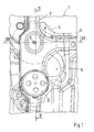
- Corresponding Fig. 1 includes a rear side body structure 1 of a vehicle, not shown otherwise, which is only partially shown here, which is preferably a passenger car, two side members 2, of which in the in Fig. 1 shown section of the body structure 1 only one can be seen.
- This longitudinal member 2 extends substantially parallel to the section line II and substantially parallel to the vehicle longitudinal direction.
- the Body structure 1 a cross member 3, which connects the two side members 2 together.
- the cross member 3 extends substantially parallel to the section line III and substantially transverse to the vehicle longitudinal direction.
- the junction between the cross member 3 and the respective side member 2 forms a connection node 4, which is indicated here by a circle drawn with a broken line. This circle essentially encloses the area of the body structure 1, in which the actual connection node 4 is located.
- Centrally located in the connection node 4 is an imaginary intersection between the cross member 3 and the respective side member. 2
- the body structure 1 has on each side of the vehicle console 5, which the respective connection node 4 from below, ie at the in Fig. 1 covers the viewer facing side.
- the console 5 is designed so that it virtually forms a negative impression of the 3D contour of the body structure 1 in the region of the connection node 4.
- the console 5 can be mounted integrally molded to the body structure 1.
- the console 5 laterally overlaps both the cross member 3 and the respective side member 2.
- a doubling of the material is achieved in conjunction with a corresponding part
- Mounting technology leads to a significant stiffening of the body structure 1 in the region of the connection node 4.
- a suitable connection technique is, for example, the setting of welds and / or welds.
- the console 5 is preferably designed as a sheet metal part.
- the respective console 5 has a bearing plate 6, in which at least one through-opening 7 penetrating the console 5 is formed.
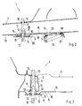
- the bearing plate 6 is designed so that it is in the FIGS. 2 and 3 indicated subframe 8 of the vehicle can be supported.
- the passage opening 7 makes it possible, the said subframe 8, when it is supported on the bearing plate 6, through the passage opening. 7 through and thus screw through the console 5 through to the body structure 1.
- the bushing 9 is attached to the longitudinal member 2.
- the bush 9 may be attached to the cross member 3.
- the bushing 9 is also fastened to the console 5.
- the bushing 9 has a thread 11 and is aligned with respect to the passage opening 7 of the bearing plate 6.
- the socket 9 is covered by the console 5.
- the subframe 8 can be screwed by means of a screw 12 shown here only partially with the body structure 1, in which the screw 12, a mounting hole 13 formed in the subframe 8, and the through hole 7 penetrates and into the socket 9 and in the thread 11 is screwed.
- the bushing 9 is designed as a standing bush, which will also be referred to below as 9.
- the standing bushing 9 has a stand-up collar 14, which protrudes radially on one of the bracket 5 facing the end of the standing sleeve 9.
- This stand-up collar 14 is supported on a bearing node 6 facing the connection node 4 inside 15 of the console 5 on the bearing plate 6.
- the bush 9 is aligned so that the stand-up collar 14 surrounds the passage opening 7. In this way, it is achieved that, on the one hand, the bearing plate 6 is braced axially between the subframe 8 and the standing bushing 9 when the subframe 8 is fastened to the body structure 1.
- the bushing 9 used here has a rod-shaped construction.
- it has a threaded portion 16 which contains the thread 11, and a rod portion 17, which is designed for example as a solid body.
- at least the longitudinal member 2 is designed as a hollow body, this results in the possibility of the socket 9 in the region of one of the console 5 end facing and in the region of one of the console 5 distant end on the side rail 2 or on the cross member 3 to support or fix. As a result, moments can also be recorded via the bush 9.
- the bearing plate 6 has at a side facing away from the respective connection node 4 outside 18 of the console 5 on a flat surface. As a result, a defined contact zone for contacting with the subframe 8 is created, which allows in particular a compensation of position tolerances. Furthermore, in the example shown, the bearing plate 6 on the inside 15 of the console 5 is also provided with a flat surface. Thus, a contact surface can be created on the inner side 15 of the bearing plate 6, which allows a compensation of positional tolerances and which is particularly favorable for the transmission of supporting forces.
- Fig. 2 can be taken that a unspecified here plate plane in which the bearing plate 6 extends at least in the region of the passage opening 7, opposite to a likewise not designated carrier plane in which, for example, a console 5 facing bottom 19 of the longitudinal member 2 at least in the region Bearing plate 6 extends, is inclined. In this way, an optimized for the reception of support forces orientation of the bearing plate 6 can be achieved.
- the bearing plate 6 is opposite to a surrounding the bearing plate 6 surrounding area of the console 5 and thus relative to the longitudinal member 2 and against the cross member 8 from. In this way, a cavity 20 is created in the region of the bearing plate 6 between the bracket 5 and the longitudinal member 2 and the cross member 3, which receives the upstanding collar 14 here.
- the bearing plate 6 is positioned within the console 5 so that it is arranged substantially centrally with respect to the connection node 4.
- the imaginary intersection of the longitudinal member 2 and the cross member 3 is located within the bearing plate 6 and in particular within the passage opening 7.
- the through hole 7 is centrally within the bearing plate 6 and thus substantially centrally with respect to the imaginary point of intersection between the longitudinal member. 2 and cross member 3 and thus here also substantially centrally within the connection node. 4
- the console 5 according to the Fig. 1 and 2
- a receiving pot 21 via which a spring device 22 on the console 5 and on this on the body structure 1 in the region of the connection node 4 can be supported.
- the pot 21 is welded, for example, to a suitable elevation 23, which is formed in the console 5. Corresponding welds are also marked with crosses and designated 10. By an appropriate design of this survey 23, the pot 21 can be easily adapted to a desired support direction.
- the receiving pot 21 is arranged in the example shown in the longitudinal direction of the longitudinal member 2 spaced from the bearing plate 6.
Landscapes
- Engineering & Computer Science (AREA)
- Chemical & Material Sciences (AREA)
- Combustion & Propulsion (AREA)
- Transportation (AREA)
- Mechanical Engineering (AREA)
- Body Structure For Vehicles (AREA)
- Vehicle Step Arrangements And Article Storage (AREA)
- Control Of Vehicles With Linear Motors And Vehicles That Are Magnetically Levitated (AREA)
- Vehicle Body Suspensions (AREA)
Abstract
Description
Die vorliegende Erfindung betrifft eine heckseitige Karosseriestruktur eines Fahrzeugs, insbesondere eines Personenkraftwagens, mit den Merkmalen des Oberbegriffs des Anspruchs 1.The present invention relates to a rear body structure of a vehicle, in particular a passenger car, having the features of the preamble of
Aus der
Andere Karosseriestrukturen sind beispielsweise aus der
Die vorliegende Erfindung beschäftigt sich mit dem Problem, für eine Karosseriestruktur der eingangs genannten Art eine verbesserte Ausführungsform anzugeben, die sich insbesondere durch eine erhöhte Funktionalität der Konsolen auszeichnet.The present invention is concerned with the problem of providing for a body structure of the type mentioned an improved embodiment, which is characterized in particular by an increased functionality of the consoles.
Dieses Problem wird erfindungsgemäß durch den Gegenstand des unabhängigen Anspruchs gelöst. Vorteilhafte Ausführungsformen sind Gegenstand der abhängigen Ansprüche.This problem is solved according to the invention by the subject matter of the independent claim. Advantageous embodiments are the subject of the dependent claims.
Die Erfindung beruht auf dem allgemeinen Gedanken, an der jeweiligen Konsole einen Lagerteller auszubilden, der so ausgestaltet ist, dass daran ein Fahrschemel des Fahrzeugs abstützbar ist. Desweiteren wird vorgeschlagen, den jeweiligen Lagerteller mit wenigstens einer Durchgangsöffnung auszustatten, die es ermöglicht, den genannten Fahrschemel quasi durch die Konsole hindurch an der Karosseriestruktur anzuschrauben. Durch die vorgeschlagene Bauweise wird zum einen erreicht, dass die Konsole eine erhöhte Funktionalität besitzt, indem daran der heckseitige Fahrschemel des Fahrzeugs abstützbar ist. Durch die Integration dieser Fahrschemelabstützung in die Konsole kann auf eine separate Abstützung des Fahrschemels verzichtet werden. Die zusätzliche Funktionalität der Konsole führt somit zu einer Reduzierung der Herstellungskosten für die Karosseriestruktur. Zum anderen wird durch den Vorschlag, den jeweiligen Fahrschemel durch die Konsole hindurch am Verbindungsknoten bzw. an der Karosseriestruktur zu befestigen, eine hinreichend feste Anbindung zwischen Fahrschemel und Karosseriestruktur ermöglicht. Erst die Befestigung des Fahrschemels an der Karosseriestruktur durch die jeweilige Konsole hindurch ermöglicht es, den Lagerteller zur Abstützung des Fahrschemels an der Konsole auszubilden. Regelmäßig ist für eine Befestigung des Fahrschemels an der Konsole die Materialstärke der vorzugsweise als Blechformteil ausgestalteten Konsole zu gering, um die erwünschte Festigkeit einer Anbindung unmittelbar an der Konsole gewährleisten zu können.The invention is based on the general idea to form a bearing plate on the respective console, which is designed so that a subframe of the vehicle can be supported thereon. Furthermore, it is proposed to equip the respective bearing plate with at least one passage opening, which makes it possible, the said Screw the subframe almost through the console to the body structure. The proposed construction on the one hand ensures that the console has increased functionality by the rear-side subframe of the vehicle can be supported on it. By integrating this subframe support in the console can be dispensed with a separate support of the subframe. The additional functionality of the console thus leads to a reduction in the manufacturing costs for the body structure. On the other hand, a sufficiently firm connection between subframe and body structure is made possible by the proposal to attach the respective subframe through the console at the connection node or on the body structure. Only the attachment of the subframe to the body structure through the respective console through it makes it possible to form the bearing plate for supporting the subframe on the console. Regularly, the material thickness of the preferably designed as a sheet metal part console is too low to ensure the desired strength of a connection directly to the console for attachment of the subframe to the console.
Entsprechend einer bevorzugten Ausführungsform kann im jeweiligen Verbindungsknoten eine Buchse am jeweiligen Längsträger und/oder am Querträger befestigt sein, die zur jeweiligen Durchgangsöffnung des Lagertellers fluchtend ausgerichtet ist, ein Gewinde aufweist und von der Konsole abgedeckt ist. Mit Hilfe einer derartigen Buchse kann auf besonders einfache und preiswerte Weise eine hinreichend feste Anschraubstelle zur Befestigung des Fahrschemels an der Karosseriestruktur geschaffen werden.According to a preferred embodiment, in the respective connection node, a bushing may be attached to the respective side member and / or the cross member, which is aligned with the respective through hole of the bearing plate, has a thread and is covered by the console. With the help of such a socket can be created in a particularly simple and inexpensive way, a sufficiently solid Anschraubstelle for mounting the subframe to the body structure.
Besonders vorteilhaft ist eine weitere Ausgestaltungsform, bei welcher die jeweilige Buchse als Stehbuchse ausgestaltet ist, die durch einen Stehkragen charakterisiert ist. Der Stehkragen ist an einer dem Verbindungsknoten zugewandten Innenseite der Konsole am Lagerteller flächig abgestützt und umschließt dabei die jeweilige Durchgangsöffnung. Durch diese Bauweise werden die Abstützkräfte, die vom Fahrschemel auf den Lagerteller übertragen werden, über die Stehbuchse in den Verbindungsknoten eingeleitet. In der Folge ist die Konsole selbst von den Stützkräften quasi entkoppelt. Insbesondere ist die Konsole so im wesentlichen keiner Biegebelastung ausgesetzt.Particularly advantageous is a further embodiment, in which the respective socket is designed as a standing bush, which is characterized by a stand-up collar. The stand-up collar is supported in a planar manner on an inner side of the console facing the connection node on the bearing plate, thereby enclosing the respective passage opening. By this construction, the supporting forces that are transmitted from the subframe to the bearing plate, via the standing bushing in the connection node initiated. As a result, the console itself is virtually decoupled from the supporting forces. In particular, the console is thus exposed to substantially no bending load.
Weitere wichtige Merkmale und Vorteile der Erfindung ergeben sich aus den Unteransprüchen, aus den Zeichnungen und aus der zugehörigen Figurenbeschreibung anhand der Zeichnungen.Other important features and advantages of the invention will become apparent from the dependent claims, from the drawings and from the associated figure description with reference to the drawings.
Es versteht sich, dass die vorstehend genannten und die nachstehend noch zu erläuternden Merkmale nicht nur in der jeweils angegebenen Kombination, sondern auch in anderen Kombinationen oder in Alleinstellung verwendbar sind, ohne den Rahmen der vorliegenden Erfindung zu verlassen.It is understood that the features mentioned above and those yet to be explained below can be used not only in the particular combination given, but also in other combinations or in isolation, without departing from the scope of the present invention.
Bevorzugte Ausführungsbeispiele der Erfindung sind in den Zeichnungen dargestellt und werden in der nachfolgenden Beschreibung näher erläutert, wobei sich gleiche Bezugszeichen auf gleiche oder ähnliche oder funktional gleiche Bauteile beziehen.Preferred embodiments of the invention are illustrated in the drawings and will be described in more detail in the following description, wherein like reference numerals refer to the same or similar or functionally identical components.
Es zeigen, jeweils schematisch,
- Fig. 1
- eine Ansicht von unten auf eine heckseitige Karosseriestruktur eines Fahrzeugs im Bereich eines Verbindungsknotens zwischen einem Längsträger und einem Querträger,
- Fig. 2
- eine vereinfachte Schnittansicht entsprechend Schnittlinien II in
Fig. 1 , - Fig. 3
- eine vereinfachte Schnittansicht entsprechend Schnittlinien III in
Fig. 1 .
- Fig. 1
- 4 a view from below of a rear body structure of a vehicle in the region of a connection node between a side member and a cross member;
- Fig. 2
- a simplified sectional view corresponding to section lines II in
Fig. 1 . - Fig. 3
- a simplified sectional view corresponding to section lines III in
Fig. 1 ,
Entsprechend
Die Karosseriestruktur 1 weist auf jeder Fahrzeugseite eine Konsole 5 auf, die den jeweiligen Verbindungsknoten 4 von unten, also an der in
Die jeweilige Konsole 5 weist einen Lagerteller 6 auf, in dem zumindest eine die Konsole 5 durchdringende Durchgangsöffnung 7 ausgebildet ist. Der Lagerteller 6 ist so ausgestaltet, dass daran ein in den
Zu diesem Zweck weist die Karosseriestruktur 1 entsprechend den
Bei den hier gezeigten, bevorzugten Ausführungsformen ist die Buchse 9 als Stehbuchse ausgestaltet, die im Folgenden ebenfalls mit 9 bezeichnet wird. Die Stehbuchse 9 weist einen Stehkragen 14 auf, der an einem der Konsole 5 zugewandten Ende der Stehbuchse 9 radial absteht. Dieser Stehkragen 14 ist an einer dem Verbindungsknoten 4 zugewandten Innenseite 15 der Konsole 5 am Lagerteller 6 flächig abgestützt. Dabei ist die Buchse 9 so ausgerichtet, dass der Stehkragen 14 die Durchgangsöffnung 7 umschließt. Auf diese Weise wird erreicht, dass einerseits der Lagerteller 6 axial zwischen dem Fahrschemel 8 und der Stehbuchse 9 verspannt wird, wenn der Fahrschemel 8 an der Karosseriestruktur 1 befestigt wird. Andererseits wird dadurch der Lagerteller 6 - abgesehen von axialen Einspannkräften - von einer axialen Kraftübertragung zwischen Fahrschemel 8 und Stehbuchse 9 und somit von axialen Übertragungskräften zwischen Fahrschemel 8 und Karosseriestruktur 1 mehr oder weniger entkoppelt. Die Konsole 5 ist im Bereich des Lagertellers 6 über die Stehbuchse 9 am Verbindungsknoten 4 bzw. an der Karosseriestruktur 1 abgestützt, wodurch mit Hilfe des Lagertellers 6 eine für die Abstützung des Fahrschemels 8 geeignete Stelle geschaffen werden kann.In the preferred embodiments shown here, the
Die hier verwendete Buchse 9 besitzt eine stabförmige Bauweise. Insbesondere besitzt sie einen Gewindeabschnitt 16, der das Gewinde 11 enthält, und einen Stababschnitt 17, der beispielsweise als Vollkörper ausgestaltet ist. Die insoweit längliche Buchse 9 durchsetzt hier den Längsträger 2 sowie den Querträger 3. Da hier zumindest der Längsträger 2 als Hohlkörper ausgestaltet ist, ergibt sich hierdurch die Möglichkeit, die Buchse 9 im Bereich eines der Konsole 5 zugewandten Endes und im Bereich eines von der Konsole 5 entfernten Endes am Längsträger 2 bzw. am Querträger 3 abzustützen bzw. zu fixieren. Hierdurch können über die Buchse 9 auch Momente aufgenommen werden.The
Der Lagerteller 6 weist an einer vom jeweiligen Verbindungsknoten 4 abgewandten Außenseite 18 der Konsole 5 eine ebene Fläche auf. Hierdurch wird eine definierte Anlagezone für die Kontaktierung mit dem Fahrschemel 8 geschaffen, die insbesondere einen Ausgleich von Lagetoleranzen ermöglicht. Desweiteren ist im gezeigten Beispiel der Lagerteller 6 an der Innenseite 15 der Konsole 5 ebenfalls mit einer ebenen Fläche ausgestattet. Somit kann auch an der Innenseite 15 des Lagertellers 6 eine Kontaktfläche geschaffen werden, die einen Ausgleich von Lagetoleranzen ermöglicht und die insbesondere für die Übertragung von Stützkräften günstig ist.The bearing
Aus
Ferner steht der Lagerteller 6 gegenüber einem den Lagerteller 6 umschließenden Umgebungsbereich der Konsole 5 und somit gegenüber dem Längsträger 2 bzw. gegenüber dem Querträger 8 ab. Auf diese Weise wird im Bereich des Lagertellers 6 zwischen der Konsole 5 und dem Längsträger 2 bzw. dem Querträger 3 ein Hohlraum 20 geschaffen, der hier den Stehkragen 14 aufnimmt.Furthermore, the bearing
Gemäß
Bei der hier gezeigten Ausführungsform weist die Konsole 5 gemäß den
Claims (11)
Applications Claiming Priority (1)
| Application Number | Priority Date | Filing Date | Title |
|---|---|---|---|
| DE102007018167A DE102007018167A1 (en) | 2007-04-18 | 2007-04-18 | Rear-side vehicle body structure |
Publications (3)
| Publication Number | Publication Date |
|---|---|
| EP1982900A2 true EP1982900A2 (en) | 2008-10-22 |
| EP1982900A3 EP1982900A3 (en) | 2009-10-21 |
| EP1982900B1 EP1982900B1 (en) | 2011-01-12 |
Family
ID=39370933
Family Applications (1)
| Application Number | Title | Priority Date | Filing Date |
|---|---|---|---|
| EP08002228A Not-in-force EP1982900B1 (en) | 2007-04-18 | 2008-02-07 | Rear end automobile body structure |
Country Status (5)
| Country | Link |
|---|---|
| US (1) | US7815248B2 (en) |
| EP (1) | EP1982900B1 (en) |
| CN (1) | CN101293536B (en) |
| AT (1) | ATE495085T1 (en) |
| DE (2) | DE102007018167A1 (en) |
Cited By (1)
| Publication number | Priority date | Publication date | Assignee | Title |
|---|---|---|---|---|
| DE102014221445A1 (en) * | 2014-10-22 | 2016-04-28 | Bayerische Motoren Werke Aktiengesellschaft | damper arrangement |
Families Citing this family (4)
| Publication number | Priority date | Publication date | Assignee | Title |
|---|---|---|---|---|
| DE102012005561B4 (en) | 2012-01-28 | 2025-01-02 | Volkswagen Aktiengesellschaft | subframe for a motor vehicle |
| JP7027999B2 (en) | 2018-03-20 | 2022-03-02 | マツダ株式会社 | Rear body structure |
| JP2019162997A (en) | 2018-03-20 | 2019-09-26 | マツダ株式会社 | Rear vehicle body structure |
| JP7020220B2 (en) * | 2018-03-20 | 2022-02-16 | マツダ株式会社 | Rear body structure |
Citations (5)
| Publication number | Priority date | Publication date | Assignee | Title |
|---|---|---|---|---|
| DE19507767A1 (en) | 1994-03-18 | 1995-09-21 | Honda Motor Co Ltd | Vehicle chassis subframe mounting structure |
| US6109653A (en) | 1997-10-30 | 2000-08-29 | Honda Giken Kogyo Kabushiki Kaisha | Vehicle body structure at a rear portion of a vehicle |
| US20020163173A1 (en) | 2001-05-07 | 2002-11-07 | Ruehl Phillip C. | Contoured hip/straight member vehicle frame |
| DE10342807A1 (en) | 2002-09-18 | 2004-04-22 | Honda Giken Kogyo K.K. | Vehicle body structure using stiffeners attached to a cross member portion between damper seats |
| DE102005044908A1 (en) | 2004-09-17 | 2006-04-06 | Suzuki Motor Corp., Hamamatsu | Rear-side vehicle body structure |
Family Cites Families (10)
| Publication number | Priority date | Publication date | Assignee | Title |
|---|---|---|---|---|
| US3913696A (en) * | 1974-05-08 | 1975-10-21 | Ford Motor Co | Chassis construction for a motor vehicle |
| DE3217959C2 (en) * | 1982-05-13 | 1993-12-09 | Porsche Ag | Device for the vibration-insulated fastening of a subframe or unit holder |
| DE3877031T2 (en) * | 1987-03-31 | 1993-05-19 | Mazda Motor | TRAINING THE REAR UNDERFLOOR OF A MOTOR VEHICLE. |
| JP3539207B2 (en) * | 1998-05-27 | 2004-07-07 | 日産自動車株式会社 | Suspension member mounting structure |
| DE19947759C2 (en) * | 1999-10-02 | 2001-11-22 | Daimler Chrysler Ag | Subframe warehouse |
| JP3674571B2 (en) * | 2001-10-15 | 2005-07-20 | 日産自動車株式会社 | Car body rear structure |
| JP4096559B2 (en) * | 2002-01-22 | 2008-06-04 | 三菱自動車工業株式会社 | Body structure |
| KR100644487B1 (en) * | 2003-08-26 | 2006-11-10 | 현대자동차주식회사 | Subframe Mounting Structure for Automobile |
| JP4297853B2 (en) | 2004-09-14 | 2009-07-15 | ダイハツ工業株式会社 | Vehicle suspension arm support structure |
| TW200802447A (en) * | 2006-06-02 | 2008-01-01 | Benq Corp | Sliding-type electronic device with a semi-automatic and magnetic opening mechanism |
-
2007
- 2007-04-18 DE DE102007018167A patent/DE102007018167A1/en not_active Withdrawn
-
2008
- 2008-02-07 AT AT08002228T patent/ATE495085T1/en active
- 2008-02-07 DE DE502008002257T patent/DE502008002257D1/en active Active
- 2008-02-07 EP EP08002228A patent/EP1982900B1/en not_active Not-in-force
- 2008-04-16 CN CN2008100937042A patent/CN101293536B/en not_active Expired - Fee Related
- 2008-04-17 US US12/104,834 patent/US7815248B2/en not_active Expired - Fee Related
Patent Citations (5)
| Publication number | Priority date | Publication date | Assignee | Title |
|---|---|---|---|---|
| DE19507767A1 (en) | 1994-03-18 | 1995-09-21 | Honda Motor Co Ltd | Vehicle chassis subframe mounting structure |
| US6109653A (en) | 1997-10-30 | 2000-08-29 | Honda Giken Kogyo Kabushiki Kaisha | Vehicle body structure at a rear portion of a vehicle |
| US20020163173A1 (en) | 2001-05-07 | 2002-11-07 | Ruehl Phillip C. | Contoured hip/straight member vehicle frame |
| DE10342807A1 (en) | 2002-09-18 | 2004-04-22 | Honda Giken Kogyo K.K. | Vehicle body structure using stiffeners attached to a cross member portion between damper seats |
| DE102005044908A1 (en) | 2004-09-17 | 2006-04-06 | Suzuki Motor Corp., Hamamatsu | Rear-side vehicle body structure |
Cited By (1)
| Publication number | Priority date | Publication date | Assignee | Title |
|---|---|---|---|---|
| DE102014221445A1 (en) * | 2014-10-22 | 2016-04-28 | Bayerische Motoren Werke Aktiengesellschaft | damper arrangement |
Also Published As
| Publication number | Publication date |
|---|---|
| CN101293536B (en) | 2011-06-15 |
| CN101293536A (en) | 2008-10-29 |
| ATE495085T1 (en) | 2011-01-15 |
| EP1982900A3 (en) | 2009-10-21 |
| DE102007018167A1 (en) | 2008-10-23 |
| US20080258501A1 (en) | 2008-10-23 |
| US7815248B2 (en) | 2010-10-19 |
| DE502008002257D1 (en) | 2011-02-24 |
| EP1982900B1 (en) | 2011-01-12 |
Similar Documents
| Publication | Publication Date | Title |
|---|---|---|
| EP1852333B1 (en) | Cross member assembly for a motor vehicle | |
| EP1912850B1 (en) | Motor vehicle body comprising a suspension strut mount | |
| EP0794106B2 (en) | Subframe for the steered wheels of a motor vehicle | |
| DE102007035004A1 (en) | Radlenkvorrichtung | |
| DE102009026299A9 (en) | Cockpit cross member for a motor vehicle | |
| WO2021047893A1 (en) | Bearing arrangement of a component on an axle carrier for a motor vehicle, and motor vehicle, in particular passenger car | |
| EP1880926B1 (en) | Motor vehicle with a cockpit module | |
| EP1982900B1 (en) | Rear end automobile body structure | |
| EP4157695B1 (en) | Fastening assembly having a bearing bracket for fastening an axle carrier, and method for mounting an axle carrier | |
| DE102011002964A1 (en) | Mounting unit for mounting transverse stabilizer in bearing in frame-like axle support of passenger car, has supporting arm molded on bearing bracket, extended in vehicle longitudinal direction and supported with section at transverse beam | |
| DE102017220203A1 (en) | Assembly storage for a drive unit in a vehicle | |
| DE102007026702A9 (en) | Axle component and method for producing an axle component | |
| EP1771310B1 (en) | Cylinder module with an axle connection | |
| EP0589299B1 (en) | Steering arrangement for motor cars | |
| EP1348613A2 (en) | Cross beam connecting the two side regions of a vehicle structure | |
| EP0501150B1 (en) | Motor vehicle with a towing device | |
| DE102004001523B4 (en) | Suspension for mounting a component in / on a vehicle body | |
| DE102004017636B4 (en) | hollow support | |
| EP0023968A1 (en) | Device for securing a hydraulic vibration damper or the like in the support tube of a wheel carrying telescopic strut | |
| DE102007019699A1 (en) | screw | |
| DE102004055406A1 (en) | Structural part for a supporting frame of a motor vehicle has binding regions one of which is formed as an open hollow holder integrated into a cast part | |
| DE102006014982A1 (en) | Transducer element for supporting an impact absorber | |
| DE102022102538B4 (en) | stop device | |
| EP2611672A1 (en) | Arrangement for securing a steering column to a body-mounted component of a vehicle | |
| DE102019203140B3 (en) | Vehicle axle with axle carrier and stabilizer and motor vehicle |
Legal Events
| Date | Code | Title | Description |
|---|---|---|---|
| PUAI | Public reference made under article 153(3) epc to a published international application that has entered the european phase |
Free format text: ORIGINAL CODE: 0009012 |
|
| AK | Designated contracting states |
Kind code of ref document: A2 Designated state(s): AT BE BG CH CY CZ DE DK EE ES FI FR GB GR HR HU IE IS IT LI LT LU LV MC MT NL NO PL PT RO SE SI SK TR |
|
| AX | Request for extension of the european patent |
Extension state: AL BA MK RS |
|
| PUAL | Search report despatched |
Free format text: ORIGINAL CODE: 0009013 |
|
| AK | Designated contracting states |
Kind code of ref document: A3 Designated state(s): AT BE BG CH CY CZ DE DK EE ES FI FR GB GR HR HU IE IS IT LI LT LU LV MC MT NL NO PL PT RO SE SI SK TR |
|
| AX | Request for extension of the european patent |
Extension state: AL BA MK RS |
|
| RAP1 | Party data changed (applicant data changed or rights of an application transferred) |
Owner name: DR. ING. H.C. F. PORSCHE AG |
|
| 17P | Request for examination filed |
Effective date: 20100421 |
|
| AKX | Designation fees paid |
Designated state(s): AT BE BG CH CY CZ DE DK EE ES FI FR GB GR HR HU IE IS IT LI LT LU LV MC MT NL NO PL PT RO SE SI SK TR |
|
| 17Q | First examination report despatched |
Effective date: 20100618 |
|
| GRAP | Despatch of communication of intention to grant a patent |
Free format text: ORIGINAL CODE: EPIDOSNIGR1 |
|
| RIC1 | Information provided on ipc code assigned before grant |
Ipc: B62D 21/11 20060101ALI20100923BHEP Ipc: B62D 25/08 20060101AFI20100923BHEP |
|
| GRAS | Grant fee paid |
Free format text: ORIGINAL CODE: EPIDOSNIGR3 |
|
| GRAA | (expected) grant |
Free format text: ORIGINAL CODE: 0009210 |
|
| AK | Designated contracting states |
Kind code of ref document: B1 Designated state(s): AT BE BG CH CY CZ DE DK EE ES FI FR GB GR HR HU IE IS IT LI LT LU LV MC MT NL NO PL PT RO SE SI SK TR |
|
| REG | Reference to a national code |
Ref country code: GB Ref legal event code: FG4D Free format text: NOT ENGLISH |
|
| REG | Reference to a national code |
Ref country code: CH Ref legal event code: EP |
|
| REG | Reference to a national code |
Ref country code: IE Ref legal event code: FG4D Free format text: LANGUAGE OF EP DOCUMENT: GERMAN |
|
| REF | Corresponds to: |
Ref document number: 502008002257 Country of ref document: DE Date of ref document: 20110224 Kind code of ref document: P |
|
| REG | Reference to a national code |
Ref country code: DE Ref legal event code: R096 Ref document number: 502008002257 Country of ref document: DE Effective date: 20110224 |
|
| REG | Reference to a national code |
Ref country code: NL Ref legal event code: VDEP Effective date: 20110112 |
|
| LTIE | Lt: invalidation of european patent or patent extension |
Effective date: 20110112 |
|
| PG25 | Lapsed in a contracting state [announced via postgrant information from national office to epo] |
Ref country code: NO Free format text: LAPSE BECAUSE OF FAILURE TO SUBMIT A TRANSLATION OF THE DESCRIPTION OR TO PAY THE FEE WITHIN THE PRESCRIBED TIME-LIMIT Effective date: 20110412 Ref country code: IS Free format text: LAPSE BECAUSE OF FAILURE TO SUBMIT A TRANSLATION OF THE DESCRIPTION OR TO PAY THE FEE WITHIN THE PRESCRIBED TIME-LIMIT Effective date: 20110512 Ref country code: PT Free format text: LAPSE BECAUSE OF FAILURE TO SUBMIT A TRANSLATION OF THE DESCRIPTION OR TO PAY THE FEE WITHIN THE PRESCRIBED TIME-LIMIT Effective date: 20110512 Ref country code: ES Free format text: LAPSE BECAUSE OF FAILURE TO SUBMIT A TRANSLATION OF THE DESCRIPTION OR TO PAY THE FEE WITHIN THE PRESCRIBED TIME-LIMIT Effective date: 20110423 Ref country code: LV Free format text: LAPSE BECAUSE OF FAILURE TO SUBMIT A TRANSLATION OF THE DESCRIPTION OR TO PAY THE FEE WITHIN THE PRESCRIBED TIME-LIMIT Effective date: 20110112 Ref country code: LT Free format text: LAPSE BECAUSE OF FAILURE TO SUBMIT A TRANSLATION OF THE DESCRIPTION OR TO PAY THE FEE WITHIN THE PRESCRIBED TIME-LIMIT Effective date: 20110112 Ref country code: SE Free format text: LAPSE BECAUSE OF FAILURE TO SUBMIT A TRANSLATION OF THE DESCRIPTION OR TO PAY THE FEE WITHIN THE PRESCRIBED TIME-LIMIT Effective date: 20110112 Ref country code: GR Free format text: LAPSE BECAUSE OF FAILURE TO SUBMIT A TRANSLATION OF THE DESCRIPTION OR TO PAY THE FEE WITHIN THE PRESCRIBED TIME-LIMIT Effective date: 20110413 Ref country code: HR Free format text: LAPSE BECAUSE OF FAILURE TO SUBMIT A TRANSLATION OF THE DESCRIPTION OR TO PAY THE FEE WITHIN THE PRESCRIBED TIME-LIMIT Effective date: 20110112 |
|
| REG | Reference to a national code |
Ref country code: IE Ref legal event code: FD4D |
|
| BERE | Be: lapsed |
Owner name: DR. ING. H.C. F. PORSCHE A.G. Effective date: 20110228 |
|
| PG25 | Lapsed in a contracting state [announced via postgrant information from national office to epo] |
Ref country code: CY Free format text: LAPSE BECAUSE OF FAILURE TO SUBMIT A TRANSLATION OF THE DESCRIPTION OR TO PAY THE FEE WITHIN THE PRESCRIBED TIME-LIMIT Effective date: 20110112 Ref country code: PL Free format text: LAPSE BECAUSE OF FAILURE TO SUBMIT A TRANSLATION OF THE DESCRIPTION OR TO PAY THE FEE WITHIN THE PRESCRIBED TIME-LIMIT Effective date: 20110112 Ref country code: FI Free format text: LAPSE BECAUSE OF FAILURE TO SUBMIT A TRANSLATION OF THE DESCRIPTION OR TO PAY THE FEE WITHIN THE PRESCRIBED TIME-LIMIT Effective date: 20110112 Ref country code: BG Free format text: LAPSE BECAUSE OF FAILURE TO SUBMIT A TRANSLATION OF THE DESCRIPTION OR TO PAY THE FEE WITHIN THE PRESCRIBED TIME-LIMIT Effective date: 20110412 Ref country code: NL Free format text: LAPSE BECAUSE OF FAILURE TO SUBMIT A TRANSLATION OF THE DESCRIPTION OR TO PAY THE FEE WITHIN THE PRESCRIBED TIME-LIMIT Effective date: 20110112 Ref country code: SI Free format text: LAPSE BECAUSE OF FAILURE TO SUBMIT A TRANSLATION OF THE DESCRIPTION OR TO PAY THE FEE WITHIN THE PRESCRIBED TIME-LIMIT Effective date: 20110112 |
|
| PG25 | Lapsed in a contracting state [announced via postgrant information from national office to epo] |
Ref country code: MC Free format text: LAPSE BECAUSE OF NON-PAYMENT OF DUE FEES Effective date: 20110228 |
|
| PG25 | Lapsed in a contracting state [announced via postgrant information from national office to epo] |
Ref country code: DK Free format text: LAPSE BECAUSE OF FAILURE TO SUBMIT A TRANSLATION OF THE DESCRIPTION OR TO PAY THE FEE WITHIN THE PRESCRIBED TIME-LIMIT Effective date: 20110112 Ref country code: EE Free format text: LAPSE BECAUSE OF FAILURE TO SUBMIT A TRANSLATION OF THE DESCRIPTION OR TO PAY THE FEE WITHIN THE PRESCRIBED TIME-LIMIT Effective date: 20110112 Ref country code: IE Free format text: LAPSE BECAUSE OF FAILURE TO SUBMIT A TRANSLATION OF THE DESCRIPTION OR TO PAY THE FEE WITHIN THE PRESCRIBED TIME-LIMIT Effective date: 20110112 |
|
| PLBE | No opposition filed within time limit |
Free format text: ORIGINAL CODE: 0009261 |
|
| STAA | Information on the status of an ep patent application or granted ep patent |
Free format text: STATUS: NO OPPOSITION FILED WITHIN TIME LIMIT |
|
| PG25 | Lapsed in a contracting state [announced via postgrant information from national office to epo] |
Ref country code: BE Free format text: LAPSE BECAUSE OF NON-PAYMENT OF DUE FEES Effective date: 20110228 Ref country code: CZ Free format text: LAPSE BECAUSE OF FAILURE TO SUBMIT A TRANSLATION OF THE DESCRIPTION OR TO PAY THE FEE WITHIN THE PRESCRIBED TIME-LIMIT Effective date: 20110112 Ref country code: RO Free format text: LAPSE BECAUSE OF FAILURE TO SUBMIT A TRANSLATION OF THE DESCRIPTION OR TO PAY THE FEE WITHIN THE PRESCRIBED TIME-LIMIT Effective date: 20110112 Ref country code: SK Free format text: LAPSE BECAUSE OF FAILURE TO SUBMIT A TRANSLATION OF THE DESCRIPTION OR TO PAY THE FEE WITHIN THE PRESCRIBED TIME-LIMIT Effective date: 20110112 |
|
| 26N | No opposition filed |
Effective date: 20111013 |
|
| PG25 | Lapsed in a contracting state [announced via postgrant information from national office to epo] |
Ref country code: MT Free format text: LAPSE BECAUSE OF FAILURE TO SUBMIT A TRANSLATION OF THE DESCRIPTION OR TO PAY THE FEE WITHIN THE PRESCRIBED TIME-LIMIT Effective date: 20110112 |
|
| REG | Reference to a national code |
Ref country code: DE Ref legal event code: R097 Ref document number: 502008002257 Country of ref document: DE Effective date: 20111013 |
|
| REG | Reference to a national code |
Ref country code: CH Ref legal event code: PL |
|
| PG25 | Lapsed in a contracting state [announced via postgrant information from national office to epo] |
Ref country code: CH Free format text: LAPSE BECAUSE OF NON-PAYMENT OF DUE FEES Effective date: 20120229 Ref country code: LI Free format text: LAPSE BECAUSE OF NON-PAYMENT OF DUE FEES Effective date: 20120229 |
|
| PG25 | Lapsed in a contracting state [announced via postgrant information from national office to epo] |
Ref country code: LU Free format text: LAPSE BECAUSE OF NON-PAYMENT OF DUE FEES Effective date: 20110207 |
|
| PG25 | Lapsed in a contracting state [announced via postgrant information from national office to epo] |
Ref country code: TR Free format text: LAPSE BECAUSE OF FAILURE TO SUBMIT A TRANSLATION OF THE DESCRIPTION OR TO PAY THE FEE WITHIN THE PRESCRIBED TIME-LIMIT Effective date: 20110112 |
|
| PG25 | Lapsed in a contracting state [announced via postgrant information from national office to epo] |
Ref country code: HU Free format text: LAPSE BECAUSE OF FAILURE TO SUBMIT A TRANSLATION OF THE DESCRIPTION OR TO PAY THE FEE WITHIN THE PRESCRIBED TIME-LIMIT Effective date: 20110112 |
|
| REG | Reference to a national code |
Ref country code: AT Ref legal event code: MM01 Ref document number: 495085 Country of ref document: AT Kind code of ref document: T Effective date: 20130207 |
|
| PG25 | Lapsed in a contracting state [announced via postgrant information from national office to epo] |
Ref country code: AT Free format text: LAPSE BECAUSE OF NON-PAYMENT OF DUE FEES Effective date: 20130207 |
|
| REG | Reference to a national code |
Ref country code: FR Ref legal event code: PLFP Year of fee payment: 9 |
|
| REG | Reference to a national code |
Ref country code: FR Ref legal event code: PLFP Year of fee payment: 10 |
|
| REG | Reference to a national code |
Ref country code: FR Ref legal event code: PLFP Year of fee payment: 11 |
|
| PGFP | Annual fee paid to national office [announced via postgrant information from national office to epo] |
Ref country code: IT Payment date: 20180227 Year of fee payment: 11 |
|
| PGFP | Annual fee paid to national office [announced via postgrant information from national office to epo] |
Ref country code: GB Payment date: 20190325 Year of fee payment: 12 |
|
| PGFP | Annual fee paid to national office [announced via postgrant information from national office to epo] |
Ref country code: FR Payment date: 20190220 Year of fee payment: 12 |
|
| PG25 | Lapsed in a contracting state [announced via postgrant information from national office to epo] |
Ref country code: IT Free format text: LAPSE BECAUSE OF NON-PAYMENT OF DUE FEES Effective date: 20190207 |
|
| GBPC | Gb: european patent ceased through non-payment of renewal fee |
Effective date: 20200207 |
|
| PG25 | Lapsed in a contracting state [announced via postgrant information from national office to epo] |
Ref country code: FR Free format text: LAPSE BECAUSE OF NON-PAYMENT OF DUE FEES Effective date: 20200229 Ref country code: GB Free format text: LAPSE BECAUSE OF NON-PAYMENT OF DUE FEES Effective date: 20200207 |
|
| PGFP | Annual fee paid to national office [announced via postgrant information from national office to epo] |
Ref country code: DE Payment date: 20220204 Year of fee payment: 15 |
|
| REG | Reference to a national code |
Ref country code: DE Ref legal event code: R119 Ref document number: 502008002257 Country of ref document: DE |
|
| PG25 | Lapsed in a contracting state [announced via postgrant information from national office to epo] |
Ref country code: DE Free format text: LAPSE BECAUSE OF NON-PAYMENT OF DUE FEES Effective date: 20230901 |