EP1982874A1 - Air belt and air belt device - Google Patents
Air belt and air belt device Download PDFInfo
- Publication number
- EP1982874A1 EP1982874A1 EP07713770A EP07713770A EP1982874A1 EP 1982874 A1 EP1982874 A1 EP 1982874A1 EP 07713770 A EP07713770 A EP 07713770A EP 07713770 A EP07713770 A EP 07713770A EP 1982874 A1 EP1982874 A1 EP 1982874A1
- Authority
- EP
- European Patent Office
- Prior art keywords
- air belt
- expandable portion
- belt
- air
- expanded
- Prior art date
- Legal status (The legal status is an assumption and is not a legal conclusion. Google has not performed a legal analysis and makes no representation as to the accuracy of the status listed.)
- Granted
Links
Images




Classifications
-
- B—PERFORMING OPERATIONS; TRANSPORTING
- B60—VEHICLES IN GENERAL
- B60R—VEHICLES, VEHICLE FITTINGS, OR VEHICLE PARTS, NOT OTHERWISE PROVIDED FOR
- B60R21/00—Arrangements or fittings on vehicles for protecting or preventing injuries to occupants or pedestrians in case of accidents or other traffic risks
- B60R21/02—Occupant safety arrangements or fittings, e.g. crash pads
- B60R21/16—Inflatable occupant restraints or confinements designed to inflate upon impact or impending impact, e.g. air bags
- B60R21/18—Inflatable occupant restraints or confinements designed to inflate upon impact or impending impact, e.g. air bags the inflatable member formed as a belt or harness or combined with a belt or harness arrangement
-
- B—PERFORMING OPERATIONS; TRANSPORTING
- B60—VEHICLES IN GENERAL
- B60R—VEHICLES, VEHICLE FITTINGS, OR VEHICLE PARTS, NOT OTHERWISE PROVIDED FOR
- B60R21/00—Arrangements or fittings on vehicles for protecting or preventing injuries to occupants or pedestrians in case of accidents or other traffic risks
- B60R21/02—Occupant safety arrangements or fittings, e.g. crash pads
- B60R21/16—Inflatable occupant restraints or confinements designed to inflate upon impact or impending impact, e.g. air bags
- B60R21/23—Inflatable members
- B60R21/231—Inflatable members characterised by their shape, construction or spatial configuration
- B60R21/2334—Expansion control features
- B60R21/2338—Tethers
-
- B—PERFORMING OPERATIONS; TRANSPORTING
- B60—VEHICLES IN GENERAL
- B60R—VEHICLES, VEHICLE FITTINGS, OR VEHICLE PARTS, NOT OTHERWISE PROVIDED FOR
- B60R21/00—Arrangements or fittings on vehicles for protecting or preventing injuries to occupants or pedestrians in case of accidents or other traffic risks
- B60R21/02—Occupant safety arrangements or fittings, e.g. crash pads
- B60R21/16—Inflatable occupant restraints or confinements designed to inflate upon impact or impending impact, e.g. air bags
- B60R21/23—Inflatable members
- B60R21/231—Inflatable members characterised by their shape, construction or spatial configuration
- B60R21/233—Inflatable members characterised by their shape, construction or spatial configuration comprising a plurality of individual compartments; comprising two or more bag-like members, one within the other
- B60R2021/23316—Inner seams, e.g. creating separate compartments or used as tethering means
-
- B—PERFORMING OPERATIONS; TRANSPORTING
- B60—VEHICLES IN GENERAL
- B60R—VEHICLES, VEHICLE FITTINGS, OR VEHICLE PARTS, NOT OTHERWISE PROVIDED FOR
- B60R21/00—Arrangements or fittings on vehicles for protecting or preventing injuries to occupants or pedestrians in case of accidents or other traffic risks
- B60R21/02—Occupant safety arrangements or fittings, e.g. crash pads
- B60R21/16—Inflatable occupant restraints or confinements designed to inflate upon impact or impending impact, e.g. air bags
- B60R21/23—Inflatable members
- B60R21/231—Inflatable members characterised by their shape, construction or spatial configuration
- B60R21/2334—Expansion control features
- B60R21/2338—Tethers
- B60R2021/23382—Internal tether means
Definitions
- the present invention relates to an air belt and an pair belt apparatus for restraining an occupant in a collision of a vehicle, or the like, and more specifically to an air belt and an air belt apparatus in which a length in a longitudinal direction is reduced when an expandable portion thereof is expanded.
- the seat belt 20 includes a shoulder belt portion 6 and a lap belt portion 7.
- the shoulder belt portion 6 is withdrawn from a retractor 3 for use in a shoulder belt, which is provided at a lower part of a center pillar 2, and is extended via a through ring 5 provided at an upper part of the center pillar 2.
- the lap belt portion 7 is withdrawn from a retractor 4 for use in a lap belt, which is provided at a lower part of the retractor 3 for use in the shoulder belt, and is extended via a waist portion of an occupant.
- a tongue apparatus 8 is provided at end portions of the shoulder belt portion 6 and the lap belt portion 7, a tongue apparatus 8 is provided.
- a buckle apparatus 9 with which the aforementioned tongue apparatus 8 is combined is provided by being fixed to a seat base 10 formed of a seat frame (not illustrated) or a slide rail (not illustrated).
- An inflator 11 for use in an air belt that is integrally provided with the aforementioned buckle apparatus 9 is provided therewith.
- the air belt apparatus is configured to be able to softly restrain the occupant by means of that when a vehicle encounters a collision, and an acceleration sensor (not illustrated) for detecting a collision detects a predetermined value or more, a high pressure gas is generated out from the inflator 11 and the high pressure gas intrudes into bags BG1 and BG2 after passing though a gas passageway in the buckle apparatus 9 and a gas passageway in the tongue apparatus 8, and causes the webbings WG1 and WG2 of respective bag-shaped belt portions 6b and 7b of the shoulder belt portion 6 and the lap belt portion 7 to be expanded and developed.
- the shoulder belt portion 6 is composed of a normal belt portion 6a that is not in contact with the occupant, and a bag-shaped belt portion 6b serving as the expanding portion.
- the bag-shaped belt portion 6b having a portion being in contact with a chest portion of the occupant is constructed from the webbing WG1 formed into a bag shape, which generates tension force at a time of the collision of the vehicle.
- the tension force of the webbing WG1 is generated along with an expansion of the webbing WG1 that is constructed from a circular knitting fabric.
- the bag BG1 is housed in an inside of the webbing WG1 of the bag-shaped belt portion 6b of the shoulder belt portion 6.
- the lap belt portion 7 is composed of a normal belt portion 7a that is not expanded and developed but is in contact with the waist portion of the occupant, and a bag-shaped belt portion 7b having a portion that is in contact with the waist portion of the occupant and is expanded and developed.
- This bag-shaped belt portion 7b is provided with the webbing WG2 formed into a bag shape, which generates tension force at a time of a collision of a vehicle.
- the tension force of the webbing WG2 is generated along with an expansion of the webbing WG2 constructed from the circular knitting fabric.
- the bag BG2 is housed in an inside of the webbing WG2 of the bag-shaped belt portion 7b of the lap belt portion 7.
- the air belt is provided with a bag-shaped belt and a knit cover surrounding the bag-shaped belt, and the knit cover is not practically extended in a longitudinal direction of the air belt, while the same is extendable in an expanding direction of the air belt, and that the length of the knit cover in the longitudinal direction is reduced at a time when the knit cover is expanded, the length of the air belt is entirely reduced along with the expansion of the air belt, and the air belt is brought to fit the occupant.
- the tension force generated in the air belt becomes smaller than the tension force generated at a time when the expandable portion is fully expanded.
- actions such as raising the gas pressure generated by means of an inflator so that the necessary tension force is generated, increasing the length of the expandable portion, or the like is required. This necessitates complicated designing work.
- An air belt of a first aspect of the present invention is characterized in that in an air belt including an expandable portion, in which the length of the expandable portion in a longitudinal direction of the air belt is reduced when the expandable portion is expanded, when the expandable portion is expanded, and when a maximum width of the expandable portion in a cross-section in a direction perpendicular to the longitudinal direction of the air belt is defined as W, and a maximum thickness of the expandable portion in a direction perpendicular to the maximum width W is defined as T, the maximum thickness T is smaller than the maximum width W.
- the maximum thickness T may be configured to be smaller than the maximum width W by means of coupling the portions facing each other in the maximum thickness direction when the expandable portion is expanded.
- the maximum thickness T may be 30 to 99% of the maximum width W.
- An air belt apparatus of a second aspect is provided with the air belt of the first aspect and an inflator that expands the air belt by means of supplying a gas thereinto.
- At least a part of the air belt may be disposed between a side surface of a seat and a side surface portion of a vehicle in a wearing state of the air belt.
- a maximum thickness T is formed to be smaller than a maximum width W at a time when an expandable portion is expanded.
- a predetermined tension force is generated at the expandable portion by means of configuring the maximum thickness T to be approximately equal to a space width between a seat and a side surface portion of a vehicle or less.
- the maximum thickness T can easily be regulated by forming a construction in which the maximum thickness T is brought to be smaller than the aforementioned maximum width W by means of coupling the portions facing each other in a direction of the maximum thickness of the air belt.
- FIGs. 1a through 1d are views illustrating an air belt at an expanded time according to an embodiment, in which Fig. 1a is a front elevation, Fig. 1b is a cross-sectional view taken along a line Ib-Ib of Fig. 1a, Fig. 1c is a schematic enlarged view of Fig. 1b, and Fig. 1d is a perspective view illustrating the air belt.
- An air belt 30 is provided with a first normal belt 31, a second normal belt 32, and an expandable portion 33 between the same.
- the expandable portion 33 is provided with a bag-shaped belt 33a and a knit cover 33b formed of a fabric surrounding the bag-shaped belt 33a, as illustrated in Fig. 1c .
- This knit cover 33b is constructed such that the same is not practically extended in a longitudinal direction by means of performing a heating drawing process, whereas the same flexibly expands and contracts in a width direction.
- a tip end of the first normal belt 31 is coupled with an anchor (not illustrated), and a base end thereof is stitched to an end of the expandable portion 33.
- a tip end of the second normal belt 32 is stitched to the other end of the expandable portion 33.
- the air belt 30 is the one that is used in a lap belt portion 7 of the aforementioned Figs. 5 and 6 .
- a gas tube (not illustrated) is inserted into the first normal belt 31, and a tip end of the gas tube reaches an inside of the expandable portion 33.
- a base end of the gas tube is coupled with an inflator (not illustrated).
- the inflator may be attached to the seat or may be attached to a vehicle member such as a vehicle body floor, a pillar, or the like.
- the inflator, a pipe-shaped member continued into the inflator, or the like may be directly coupled with the expandable portion 33.
- a tongue is attached to the tip end of the first normal belt, and the tongue is configured to be attached to or detached from the buckle.
- a blowing-out coupler for blowing out a gas from the inflator is provided in the buckle, and a gas-receiving coupler, which is attached to or detached from the blowing-out coupler, is provided in the tongue.
- the portions of the bag-shaped belt 33a which face each other, are coupled by means of a coupling portion 34 formed of a stitching thread.
- the coupling portion 34 couples not only the bag-shaped belt 33a but also the portions of the knit cover 33b facing each other.
- This coupling portion 34 is provided at one place in the vicinity of the middle portion in a longitudinal direction of the air belt 30 in the expandable portion 33, and in the vicinity of the middle portion in a direction of the maximum width W, described later.
- the coupling portion 34 may be provided two or more in number at intervals in the longitudinal direction of the air belt 30.
- the coupling portion 34 may be provided two or more in number at intervals in the direction of the maximum width W.
- the coupling portion 34 has a ring shape, the same may also have an elliptic ring shape.
- the expandable portion 33 is expanded in a flat shape.
- the maximum width W and the maximum thickness T of the expandable portion 33 at the time when the same is expanded are respectively illustrated in Fig. 1b .
- the maximum width W is the maximum width in a direction perpendicular to the longitudinal direction of the air belt 30.
- the maximum thickness is the maximum thickness of the expandable portion 33 in a direction perpendicular to the direction of the maximum width W.
- a percentage of the maximum thickness T to the maximum width W: T/W x 100% is preferable to be from about 30 to about 99%, and specifically, from about 40 to about 80%.
- the maximum thickness T is preferable to be about 140 mm or less, i.e., for example, from about 60 mm to 100 mm.
- This air belt 30 is preferable to be used as a lap belt, and the second normal belt 32 is pulled around along a front surface of a waist portion of the occupant.
- an air belt apparatus provided with the thus constructed air belt 30, when the inflator is operated along with a collision of an automobile, or the like, the gas from the inflator is supplied to the expandable portion 33, the expandable portion 33 is expanded, and the air belt 30 fits the occupant.
- the knit cover of the expandable portion 33 is not extended in the longitudinal direction of the air belt 30, a length of the expandable portion 33 is reduced along with the expansion of the expandable portion 33, and the tension force is generated in the air belt 30.
- the expandable portion 33 is expanded in a flat shape, and thereby even in a case that a part of or entire expandable portion 33 exists in a narrow space between the seat and the side surface portion of the vehicle such as a door trim, a B pillar, or the like, the expandable portion 33 can be expanded up to an approximately fully open condition by means of forming the maximum thickness T of the expandable portion 33 to have an approximately the same width of the space or less, and the predetermined tension force is generated to the expandable portion 33.
- the occupant can be restrained by generating the tension force at the value as designed, to the air belt 30 without taking steps such as using an inflator having a large output power, extending the length of the expandable portion, or the like.
- Figs. 2a through 2d are views illustrating an air belt at an expanded time according to another embodiment, in which Fig. 2a is a front elevation, Fig. 2b is a cross-sectional view taken along a line IIb-IIb of Fig. 2a, Fig. 2c is a perspective view illustrating a tether, and Fig. 2d is a perspective view illustrating the air belt.
- the coupling portion is constructed of a tether 35 instead of the coupling portion 34 formed of the stitching thread.
- the tether 35 is coupled with respective faces of the bag-shaped belt 33A facing each other at a time of expanding operation thereof, by means of a stitching operation or the like.
- This tether 35 extends in a longitudinal direction of the air belt 30A. Further, this tether 35 is positioned at a center in a direction of the maximum width W.
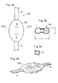
- Figs. 3a through 3d are views illustrating an air belt at an expanded time according to still another embodiment, in which Fig. 3a is a front elevation, Fig. 3b is a cross-sectional view taken along a line IIIb-IIIb of Fig. 3a, Fig. 3c is a perspective view illustrating a tether, and Fig. 3d is a perspective view illustrating the air belt.
- the thickness of expanded expandable portion 33B is also regulated by means of the tether 36.
- This tether 36 extends in a direction of the maximum width W.
- the tether 36 is provided two in number at an interval in the longitudinal direction of the air belt 30B, the same may be provided three or more in number.
- Figs. 4a through 4d are views illustrating an air belt at an expanded time according to another embodiment, in which Fig. 4a is a front elevation, Fig. 4b is a cross-sectional view taken along a line IVb-IVIb of Fig. 4a, and Fig. 4c is a perspective view illustrating the air belt.
- a straight-line-shaped coupling portion 37 formed of the stitching thread extends from one end to the other end of the expandable portion 33C in the longitudinal direction.
- an inside of the expandable portion 33C is partitioned into two chambers of one half-side and the other half-side in the direction of the maximum width W, and each of the chambers is expanded by means of the gas from the inflator, respectively.
- the length of the coupling portion 37 may be shorter than the length from one end to the other end of the expandable portion 33C. Further, two or more ridges of the coupling portions 37 may be provided. A plurality of ridges of the coupling portions 37 being extending approximately in parallel with each other may be provided.
- these air belts 30A, 30B, 30C are the same as that of the aforementioned air belt 30, and therefore the same reference numerals denote the same elements.
- the expandable portion is also composed of a bag-shaped belt and a knit cover.
- any of the aforementioned embodiments is an example of the present invention, and the present invention can also employ the configurations other than that illustrated above.
- a device to regulate the maximum thickness of the expandable portion is not limited to that illustrated in the drawings.
- the air belt of the present invention may be applied to a shoulder belt.
- Japanese Patent Application Japanese Patent Application No. 2006-031407 filed on February 8th, 2006, the entire contents of which are incorporated by reference.
Landscapes
- Engineering & Computer Science (AREA)
- Mechanical Engineering (AREA)
- Air Bags (AREA)
- Automotive Seat Belt Assembly (AREA)
Abstract


Description
- The present invention relates to an air belt and an pair belt apparatus for restraining an occupant in a collision of a vehicle, or the like, and more specifically to an air belt and an air belt apparatus in which a length in a longitudinal direction is reduced when an expandable portion thereof is expanded.
- As an air belt apparatus, in which a part of webbing of a seat belt apparatus is configured to be an expandable portion, for example, the one described in Japanese Unexamined Patent Application Publication No.
2003-312439 -
Figs. 5 and 6 illustrate the air belt apparatus described in the publication. Theseat belt 20 includes a shoulder belt portion 6 and a lap belt portion 7. The shoulder belt portion 6 is withdrawn from aretractor 3 for use in a shoulder belt, which is provided at a lower part of a center pillar 2, and is extended via a through ring 5 provided at an upper part of the center pillar 2. Further, the lap belt portion 7 is withdrawn from aretractor 4 for use in a lap belt, which is provided at a lower part of theretractor 3 for use in the shoulder belt, and is extended via a waist portion of an occupant. At end portions of the shoulder belt portion 6 and the lap belt portion 7, a tongue apparatus 8 is provided. A buckle apparatus 9 with which the aforementioned tongue apparatus 8 is combined is provided by being fixed to aseat base 10 formed of a seat frame (not illustrated) or a slide rail (not illustrated). Aninflator 11 for use in an air belt that is integrally provided with the aforementioned buckle apparatus 9 is provided therewith. - The air belt apparatus is configured to be able to softly restrain the occupant by means of that when a vehicle encounters a collision, and an acceleration sensor (not illustrated) for detecting a collision detects a predetermined value or more, a high pressure gas is generated out from the
inflator 11 and the high pressure gas intrudes into bags BG1 and BG2 after passing though a gas passageway in the buckle apparatus 9 and a gas passageway in the tongue apparatus 8, and causes the webbings WG1 and WG2 of respective bag-shaped belt portions 6b and 7b of the shoulder belt portion 6 and the lap belt portion 7 to be expanded and developed. - The shoulder belt portion 6 is composed of a
normal belt portion 6a that is not in contact with the occupant, and a bag-shaped belt portion 6b serving as the expanding portion. The bag-shaped belt portion 6b having a portion being in contact with a chest portion of the occupant is constructed from the webbing WG1 formed into a bag shape, which generates tension force at a time of the collision of the vehicle. The tension force of the webbing WG1 is generated along with an expansion of the webbing WG1 that is constructed from a circular knitting fabric. The bag BG1 is housed in an inside of the webbing WG1 of the bag-shaped belt portion 6b of the shoulder belt portion 6. - The lap belt portion 7 is composed of a normal belt portion 7a that is not expanded and developed but is in contact with the waist portion of the occupant, and a bag-shaped belt portion 7b having a portion that is in contact with the waist portion of the occupant and is expanded and developed. This bag-shaped belt portion 7b is provided with the webbing WG2 formed into a bag shape, which generates tension force at a time of a collision of a vehicle. The tension force of the webbing WG2 is generated along with an expansion of the webbing WG2 constructed from the circular knitting fabric. The bag BG2 is housed in an inside of the webbing WG2 of the bag-shaped belt portion 7b of the lap belt portion 7.
- [Patent Document 1] Japanese Unexamined Patent Application Publication No.
2003-312439 - In a case that the air belt is provided with a bag-shaped belt and a knit cover surrounding the bag-shaped belt, and the knit cover is not practically extended in a longitudinal direction of the air belt, while the same is extendable in an expanding direction of the air belt, and that the length of the knit cover in the longitudinal direction is reduced at a time when the knit cover is expanded, the length of the air belt is entirely reduced along with the expansion of the air belt, and the air belt is brought to fit the occupant.
- However, in a case that at least a part of the expandable portion is expanded in a manner so as to be sandwiched in a narrow space between a seat and a side surface portion of the vehicle, and the expansion of the expandable portion is limited by the seat and the side surface portion of the vehicle, and is not fully expanded, the tension force generated in the air belt becomes smaller than the tension force generated at a time when the expandable portion is fully expanded. Hitherto, even in such a case, actions such as raising the gas pressure generated by means of an inflator so that the necessary tension force is generated, increasing the length of the expandable portion, or the like is required. This necessitates complicated designing work.
- It is an object of the present invention to provide an air belt to which tension force as designed is generated when an expandable portion is expanded, and an air belt apparatus provided with the air belt.
- An air belt of a first aspect of the present invention is characterized in that in an air belt including an expandable portion, in which the length of the expandable portion in a longitudinal direction of the air belt is reduced when the expandable portion is expanded, when the expandable portion is expanded, and when a maximum width of the expandable portion in a cross-section in a direction perpendicular to the longitudinal direction of the air belt is defined as W, and a maximum thickness of the expandable portion in a direction perpendicular to the maximum width W is defined as T, the maximum thickness T is smaller than the maximum width W.
- The maximum thickness T may be configured to be smaller than the maximum width W by means of coupling the portions facing each other in the maximum thickness direction when the expandable portion is expanded.
- The maximum thickness T may be 30 to 99% of the maximum width W.
- An air belt apparatus of a second aspect is provided with the air belt of the first aspect and an inflator that expands the air belt by means of supplying a gas thereinto.
- At least a part of the air belt may be disposed between a side surface of a seat and a side surface portion of a vehicle in a wearing state of the air belt.
-
- [
Fig. 1] Figs. 1a through 1d are views illustrating an air belt at an expanded time according to an embodiment, in whichFig. 1a is a front elevation,Fig. 1b is a cross-sectional view taken along a line Ib-Ib ofFig. 1a, Fig. 1c is a schematic enlarged view ofFig. 1b, and Fig. 1d is a perspective view illustrating the air belt. - [
Fig. 2] Figs. 2a through 2d are views illustrating an air belt at an expanded time according to another embodiment, in whichFig. 2a is a front elevation,Fig. 2b is a cross-sectional view taken along a line IIb-IIb ofFig. 2a, Fig. 2c is a perspective view illustrating a tether, andFig. 2d is a perspective view illustrating the air belt. - [
Fig. 3] Figs. 3a through 3d are views illustrating an air belt at an expanded time according to still another embodiment, in whichFig. 3a is a front elevation,Fig. 3b is a cross-sectional view taken along a line IIIb-IIIb ofFig. 3a, Fig. 3c is a perspective view illustrating a tether, andFig. 3d is a perspective view illustrating the air belt. - [
Fig. 4] Figs. 4a through 4d are views illustrating an air belt at an expanded time according to another embodiment, in whichFig. 4a is a front elevation,Fig. 4b is a cross-sectional view taken along a line IVb-IVIb ofFig. 4a, and Fig. 4c is a perspective view illustrating the air belt. - [
Fig. 5] Fig. 5 is a front elevation illustrating a hitherto known example. - [
Fig. 6] Fig. 6 is a side elevation illustrating a hitherto known example. - In an air belt of a first aspect, a maximum thickness T is formed to be smaller than a maximum width W at a time when an expandable portion is expanded. Hence, a predetermined tension force is generated at the expandable portion by means of configuring the maximum thickness T to be approximately equal to a space width between a seat and a side surface portion of a vehicle or less.
- The maximum thickness T can easily be regulated by forming a construction in which the maximum thickness T is brought to be smaller than the aforementioned maximum width W by means of coupling the portions facing each other in a direction of the maximum thickness of the air belt.
- Hereinbelow, an embodiment will be explained with reference to the drawings.
Figs. 1a through 1d are views illustrating an air belt at an expanded time according to an embodiment, in whichFig. 1a is a front elevation,Fig. 1b is a cross-sectional view taken along a line Ib-Ib ofFig. 1a, Fig. 1c is a schematic enlarged view ofFig. 1b, and Fig. 1d is a perspective view illustrating the air belt. - An
air belt 30 is provided with a firstnormal belt 31, a secondnormal belt 32, and anexpandable portion 33 between the same. - The
expandable portion 33 is provided with a bag-shapedbelt 33a and aknit cover 33b formed of a fabric surrounding the bag-shapedbelt 33a, as illustrated inFig. 1c . Thisknit cover 33b is constructed such that the same is not practically extended in a longitudinal direction by means of performing a heating drawing process, whereas the same flexibly expands and contracts in a width direction. - A tip end of the first
normal belt 31 is coupled with an anchor (not illustrated), and a base end thereof is stitched to an end of theexpandable portion 33. A tip end of the secondnormal belt 32 is stitched to the other end of theexpandable portion 33. - The
air belt 30 is the one that is used in a lap belt portion 7 of the aforementionedFigs. 5 and 6 . - A gas tube (not illustrated) is inserted into the first
normal belt 31, and a tip end of the gas tube reaches an inside of theexpandable portion 33. A base end of the gas tube is coupled with an inflator (not illustrated). The inflator may be attached to the seat or may be attached to a vehicle member such as a vehicle body floor, a pillar, or the like. - Incidentally, although the first
normal belt 31 is coupled with theexpandable portion 33 in this embodiment, the inflator, a pipe-shaped member continued into the inflator, or the like may be directly coupled with theexpandable portion 33. Further, it is applicable that a tongue is attached to the tip end of the first normal belt, and the tongue is configured to be attached to or detached from the buckle. In this case, it is sufficient that a blowing-out coupler for blowing out a gas from the inflator is provided in the buckle, and a gas-receiving coupler, which is attached to or detached from the blowing-out coupler, is provided in the tongue. - In order to regulate the thickness of the aforementioned
expandable portion 33 at the time when expanded, in this embodiment, the portions of the bag-shapedbelt 33a, which face each other, are coupled by means of acoupling portion 34 formed of a stitching thread. Thecoupling portion 34 couples not only the bag-shapedbelt 33a but also the portions of theknit cover 33b facing each other. - This
coupling portion 34 is provided at one place in the vicinity of the middle portion in a longitudinal direction of theair belt 30 in theexpandable portion 33, and in the vicinity of the middle portion in a direction of the maximum width W, described later. However, thecoupling portion 34 may be provided two or more in number at intervals in the longitudinal direction of theair belt 30. Furthermore, when the width of theexpandable portion 33 is large, thecoupling portion 34 may be provided two or more in number at intervals in the direction of the maximum width W. Although thecoupling portion 34 has a ring shape, the same may also have an elliptic ring shape. - By means of providing the
coupling portion 34, theexpandable portion 33 is expanded in a flat shape. The maximum width W and the maximum thickness T of theexpandable portion 33 at the time when the same is expanded are respectively illustrated inFig. 1b . The maximum width W is the maximum width in a direction perpendicular to the longitudinal direction of theair belt 30. The maximum thickness is the maximum thickness of theexpandable portion 33 in a direction perpendicular to the direction of the maximum width W. - Incidentally, a percentage of the maximum thickness T to the maximum width W: T/W x 100% is preferable to be from about 30 to about 99%, and specifically, from about 40 to about 80%. Moreover, the maximum thickness T is preferable to be about 140 mm or less, i.e., for example, from about 60 mm to 100 mm.
- This
air belt 30 is preferable to be used as a lap belt, and the secondnormal belt 32 is pulled around along a front surface of a waist portion of the occupant. - In an air belt apparatus provided with the thus constructed
air belt 30, when the inflator is operated along with a collision of an automobile, or the like, the gas from the inflator is supplied to theexpandable portion 33, theexpandable portion 33 is expanded, and theair belt 30 fits the occupant. At this moment, since the knit cover of theexpandable portion 33 is not extended in the longitudinal direction of theair belt 30, a length of theexpandable portion 33 is reduced along with the expansion of theexpandable portion 33, and the tension force is generated in theair belt 30. - In this embodiment, the
expandable portion 33 is expanded in a flat shape, and thereby even in a case that a part of or entireexpandable portion 33 exists in a narrow space between the seat and the side surface portion of the vehicle such as a door trim, a B pillar, or the like, theexpandable portion 33 can be expanded up to an approximately fully open condition by means of forming the maximum thickness T of theexpandable portion 33 to have an approximately the same width of the space or less, and the predetermined tension force is generated to theexpandable portion 33. - Hence, the occupant can be restrained by generating the tension force at the value as designed, to the
air belt 30 without taking steps such as using an inflator having a large output power, extending the length of the expandable portion, or the like. -
Figs. 2a through 2d are views illustrating an air belt at an expanded time according to another embodiment, in whichFig. 2a is a front elevation,Fig. 2b is a cross-sectional view taken along a line IIb-IIb ofFig. 2a, Fig. 2c is a perspective view illustrating a tether, andFig. 2d is a perspective view illustrating the air belt. - In this embodiment, the coupling portion is constructed of a
tether 35 instead of thecoupling portion 34 formed of the stitching thread. Thetether 35 is coupled with respective faces of the bag-shapedbelt 33A facing each other at a time of expanding operation thereof, by means of a stitching operation or the like. Thistether 35 extends in a longitudinal direction of theair belt 30A. Further, thistether 35 is positioned at a center in a direction of the maximum width W. By means of providing thetether 35, the thickness of anexpandable portion 33B at the time of expanding operation is regulated. -
Figs. 3a through 3d are views illustrating an air belt at an expanded time according to still another embodiment, in whichFig. 3a is a front elevation,Fig. 3b is a cross-sectional view taken along a line IIIb-IIIb ofFig. 3a, Fig. 3c is a perspective view illustrating a tether, andFig. 3d is a perspective view illustrating the air belt. - In this embodiment, the thickness of expanded
expandable portion 33B is also regulated by means of thetether 36. Thistether 36 extends in a direction of the maximum width W. Although thetether 36 is provided two in number at an interval in the longitudinal direction of theair belt 30B, the same may be provided three or more in number. -
Figs. 4a through 4d are views illustrating an air belt at an expanded time according to another embodiment, in whichFig. 4a is a front elevation,Fig. 4b is a cross-sectional view taken along a line IVb-IVIb ofFig. 4a, and Fig. 4c is a perspective view illustrating the air belt. - In an
air belt 30C in this embodiment, a straight-line-shapedcoupling portion 37 formed of the stitching thread extends from one end to the other end of theexpandable portion 33C in the longitudinal direction. By means of thecoupling portion 37, an inside of theexpandable portion 33C is partitioned into two chambers of one half-side and the other half-side in the direction of the maximum width W, and each of the chambers is expanded by means of the gas from the inflator, respectively. - Incidentally, the length of the
coupling portion 37 may be shorter than the length from one end to the other end of theexpandable portion 33C. Further, two or more ridges of thecoupling portions 37 may be provided. A plurality of ridges of thecoupling portions 37 being extending approximately in parallel with each other may be provided. - Other construction of these
air belts aforementioned air belt 30, and therefore the same reference numerals denote the same elements. Incidentally, inFigs. 2a through 4d , although not illustrated, the expandable portion is also composed of a bag-shaped belt and a knit cover. By means of using theseair belts 30A through 30C, the same advantage as that of theair belt 30 is also obtained. - Any of the aforementioned embodiments is an example of the present invention, and the present invention can also employ the configurations other than that illustrated above. For example, a device to regulate the maximum thickness of the expandable portion is not limited to that illustrated in the drawings. In addition, the air belt of the present invention may be applied to a shoulder belt.
- Incidentally, the present invention is based on Japanese Patent Application (Japanese Patent Application No.
2006-031407
Claims (11)
- An air belt including an expandable portion, in which a length of the expandable portion in a longitudinal direction of the air belt is reduced when the expandable portion is expanded,
wherein when the expandable portion is expanded, and when a maximum width of the expandable portion in a cross-section in a direction perpendicular to the longitudinal direction of the air belt is defined as W, and a maximum thickness of the expandable portion in a direction perpendicular to the maximum width W is defined as T, the maximum thickness T is smaller than the maximum width W. - The air belt according to Claim 1, wherein the maximum thickness T is configured to be smaller than the maximum width W by means of coupling the portions facing each other in the maximum thickness direction when the expandable portion is expanded.
- The air belt according to Claim 1, wherein the maximum thickness T is 30 to 99% of the maximum width W.
- The air belt according to Claim 1, wherein the maximum thickness T is 40 to 80% of the maximum width W.
- The air belt according to Claim 2, wherein a coupling is formed of a stitching thread.
- The air belt according to Claim 5, wherein the coupling portion is formed into a ring shape or an elliptic ring shape.
- The air belt according to Claim 5, wherein the coupling portion is formed into a straight-line shape.
- The air belt according to Claim 7, wherein the coupling portion extends in the longitudinal direction of the air belt.
- The air belt according to Claim 2, wherein the coupling is formed of a tether.
- The air belt apparatus including an expandable air belt, and an inflator expanding the air belt by means of supplying a gas thereinto, wherein the air belt is the air belt according to Claim 1.
- The air belt apparatus according to Claim 10, wherein at least a part of the air belt is disposed between a side surface of a seat and a side surface portion of a vehicle in a wearing state of the air belt.
Applications Claiming Priority (2)
| Application Number | Priority Date | Filing Date | Title |
|---|---|---|---|
| JP2006031407A JP2007210420A (en) | 2006-02-08 | 2006-02-08 | Air belt and air belt device |
| PCT/JP2007/051770 WO2007091486A1 (en) | 2006-02-08 | 2007-02-02 | Air belt and air belt device |
Publications (3)
| Publication Number | Publication Date |
|---|---|
| EP1982874A1 true EP1982874A1 (en) | 2008-10-22 |
| EP1982874A4 EP1982874A4 (en) | 2009-07-15 |
| EP1982874B1 EP1982874B1 (en) | 2010-12-08 |
Family
ID=38345088
Family Applications (1)
| Application Number | Title | Priority Date | Filing Date |
|---|---|---|---|
| EP07713770A Ceased EP1982874B1 (en) | 2006-02-08 | 2007-02-02 | Air belt and air belt device |
Country Status (5)
| Country | Link |
|---|---|
| US (1) | US7766382B2 (en) |
| EP (1) | EP1982874B1 (en) |
| JP (1) | JP2007210420A (en) |
| DE (1) | DE602007011038D1 (en) |
| WO (1) | WO2007091486A1 (en) |
Families Citing this family (30)
| Publication number | Priority date | Publication date | Assignee | Title |
|---|---|---|---|---|
| US7708312B2 (en) * | 2008-01-14 | 2010-05-04 | Key Safety Systems, Inc. | Three-point safety belt system with integral air bag |
| US7980590B2 (en) * | 2008-03-19 | 2011-07-19 | Amsafe, Inc. | Inflatable personal restraint systems having web-mounted inflators and associated methods of use and manufacture |
| US7665761B1 (en) * | 2008-03-27 | 2010-02-23 | Amsafe, Inc. | Inflatable personal restraint systems and associated methods of use and manufacture |
| JP5081716B2 (en) * | 2008-05-09 | 2012-11-28 | 日産自動車株式会社 | Crew protection device |
| JP4569684B2 (en) * | 2008-08-01 | 2010-10-27 | トヨタ自動車株式会社 | Vehicle occupant restraint system |
| IT1406402B1 (en) * | 2010-09-10 | 2014-02-21 | Technogym Spa | GINNICA EQUIPMENT |
| USD688156S1 (en) | 2011-05-16 | 2013-08-20 | Amsafe, Inc. | Connector for a seatbelt airbag |
| US8439398B2 (en) | 2011-07-29 | 2013-05-14 | Amsafe, Inc. | Inflator connectors for inflatable personal restraints and associated systems and methods |
| US9511866B2 (en) | 2012-03-19 | 2016-12-06 | Amsafe, Inc. | Structure mounted airbag assemblies and associated systems and methods |
| US8523220B1 (en) | 2012-03-19 | 2013-09-03 | Amsafe, Inc. | Structure mounted airbag assemblies and associated systems and methods |
| US9616747B1 (en) | 2013-01-29 | 2017-04-11 | Intelligent Technologies International, Inc. | Method for controlling travel of golf carts and all-terrain vehicles |
| JP5850008B2 (en) * | 2013-08-21 | 2016-02-03 | トヨタ自動車株式会社 | Air belt device |
| JP6113048B2 (en) | 2013-10-23 | 2017-04-12 | 株式会社東海理化電機製作所 | Seat belt device |
| JP6113063B2 (en) * | 2013-12-04 | 2017-04-12 | 株式会社東海理化電機製作所 | Seat belt device |
| EP2905185B1 (en) * | 2014-02-06 | 2018-03-14 | Autoliv Development AB | Motor vehicle with an airbag between a wheel and the car body and airbag unit |
| JP6175012B2 (en) * | 2014-02-24 | 2017-08-02 | 株式会社東海理化電機製作所 | Manufacturing method of seat belt device |
| JP6300636B2 (en) * | 2014-05-22 | 2018-03-28 | 株式会社東海理化電機製作所 | Webbing device |
| JP6200856B2 (en) * | 2014-06-03 | 2017-09-20 | 株式会社東海理化電機製作所 | Webbing device |
| US9434339B2 (en) * | 2014-08-27 | 2016-09-06 | Autoliv Asp, Inc. | Inflatable seat belt with a tethered gas delivery fill tube |
| US9393926B2 (en) * | 2014-08-27 | 2016-07-19 | Autoliv Asp, Inc. | Folding patterns of an inflatable seat belt |
| US9352839B2 (en) | 2014-10-02 | 2016-05-31 | Amsafe, Inc. | Active positioning airbag assembly and associated systems and methods |
| DE102014222654B4 (en) * | 2014-11-06 | 2022-08-25 | Autoliv Development Ab | Webbing for a seat belt device and seat belt device |
| US9944245B2 (en) | 2015-03-28 | 2018-04-17 | Amsafe, Inc. | Extending pass-through airbag occupant restraint systems, and associated systems and methods |
| US9925950B2 (en) | 2015-04-11 | 2018-03-27 | Amsafe, Inc. | Active airbag vent system |
| US10604259B2 (en) | 2016-01-20 | 2020-03-31 | Amsafe, Inc. | Occupant restraint systems having extending restraints, and associated systems and methods |
| JP6438996B2 (en) * | 2017-03-27 | 2018-12-19 | 株式会社Subaru | Crew protection device |
| JP6913508B2 (en) * | 2017-05-22 | 2021-08-04 | Joyson Safety Systems Japan株式会社 | Airbag device and seat belt device |
| US20190344743A1 (en) * | 2018-05-14 | 2019-11-14 | Ford Global Technologies, Llc | Seatbelt assembly |
| US11648905B2 (en) * | 2020-08-11 | 2023-05-16 | Toyoda Gosei Co., Ltd. | Occupant protection device |
| KR20220094603A (en) * | 2020-12-29 | 2022-07-06 | 현대자동차주식회사 | Belt tactile apparatus for vehicle, and method for controlling the apparatus |
Family Cites Families (35)
| Publication number | Priority date | Publication date | Assignee | Title |
|---|---|---|---|---|
| BE756451A (en) * | 1970-02-21 | 1971-03-01 | Rutzki Edith | SEATBELT |
| US3801156A (en) * | 1971-11-15 | 1974-04-02 | H Granig | Safety-belt |
| GB1416517A (en) * | 1971-11-15 | 1975-12-03 | Project Lab Ltd | Safety belts |
| US3841654A (en) * | 1972-09-21 | 1974-10-15 | Allied Chem | Vehicle safety system |
| DE2358070A1 (en) * | 1972-11-27 | 1974-06-06 | Nissan Motor | SAFETY BELT |
| US3970329A (en) * | 1973-01-10 | 1976-07-20 | Allied Chemical Corporation | Inflatable band restraint stitching |
| US3866940A (en) * | 1973-01-11 | 1975-02-18 | Allied Chem | Differentially inflatable restraining band for vehicles |
| US3865398A (en) * | 1973-02-05 | 1975-02-11 | Toni Woll | Expandable crash-restraining means |
| US3888503A (en) * | 1973-02-22 | 1975-06-10 | Allied Chem | Limiting of continuous extent of inflatable restraint |
| JPS576545Y2 (en) * | 1973-05-09 | 1982-02-06 | ||
| GB1478967A (en) * | 1973-07-09 | 1977-07-06 | Safety belts | |
| US5062662A (en) * | 1990-05-16 | 1991-11-05 | Cameron Robert W | Vehicle seatbelt having an integral airbag |
| JP3057114B2 (en) * | 1991-10-21 | 2000-06-26 | タカタ株式会社 | Inflatable seat belt device |
| US5282648A (en) | 1992-06-01 | 1994-02-01 | Simula Inc. | Inflatable body and head restraint system |
| JP3110881B2 (en) * | 1992-08-06 | 2000-11-20 | タカタ株式会社 | Inflatable seat belt device |
| CA2102334A1 (en) | 1993-11-03 | 1995-05-04 | Hang-Sup Ohm | Automobile safety air belt with air bag |
| US5466002A (en) * | 1994-06-30 | 1995-11-14 | Takata Corporation | Inflatable seat belt with leak detection device |
| DE29517372U1 (en) * | 1995-11-02 | 1996-02-01 | Trw Repa Gmbh | Airbag side impact protection device |
| US6419263B1 (en) * | 1998-05-11 | 2002-07-16 | The B. F. Goodrich Company | Seatbelt system having seamless inflatable member |
| DE19725558C2 (en) * | 1997-06-12 | 2001-11-29 | Petri Ag | Airbag restraint system |
| DE19911973A1 (en) | 1999-03-17 | 2000-09-28 | Johann Berger | Two-layer inflatable strap used for safety belts is tubular and has top woven layer and bottom woven layer |
| JP4331853B2 (en) * | 2000-03-23 | 2009-09-16 | 本田技研工業株式会社 | Air belt device |
| JP4380021B2 (en) * | 2000-05-11 | 2009-12-09 | タカタ株式会社 | Air belt device |
| JP3951747B2 (en) * | 2002-03-01 | 2007-08-01 | タカタ株式会社 | Externally deployable airbag device |
| US6705641B2 (en) * | 2002-03-08 | 2004-03-16 | Autoliv Asp, Inc. | Inflatable seat belt system |
| JP3911189B2 (en) | 2002-04-23 | 2007-05-09 | 本田技研工業株式会社 | Air belt device |
| JP4122904B2 (en) | 2002-09-05 | 2008-07-23 | タカタ株式会社 | Crew protection device |
| US7168733B2 (en) * | 2002-12-27 | 2007-01-30 | Takata Corporation | Airbag apparatus |
| US7207595B2 (en) * | 2003-03-27 | 2007-04-24 | Toyoda Gosei Co., Ltd. | Side airbag apparatus |
| JP2005231504A (en) | 2004-02-19 | 2005-09-02 | Takata Corp | Occupant crash protection device |
| JP2005239055A (en) | 2004-02-27 | 2005-09-08 | Takata Corp | Occupant crash protection device |
| JP4734933B2 (en) | 2004-02-27 | 2011-07-27 | タカタ株式会社 | Vehicle occupant protection system and inflator |
| JP4391273B2 (en) | 2004-03-05 | 2009-12-24 | 芦森工業株式会社 | Airbag device |
| JP2005271888A (en) | 2004-03-26 | 2005-10-06 | Takata Corp | Air belt device |
| US7434833B2 (en) | 2004-07-14 | 2008-10-14 | Mazda Motor Corporation | Seat belt device for vehicle |
-
2006
- 2006-02-08 JP JP2006031407A patent/JP2007210420A/en active Pending
-
2007
- 2007-02-02 WO PCT/JP2007/051770 patent/WO2007091486A1/en not_active Ceased
- 2007-02-02 DE DE602007011038T patent/DE602007011038D1/en active Active
- 2007-02-02 EP EP07713770A patent/EP1982874B1/en not_active Ceased
- 2007-02-02 US US12/223,592 patent/US7766382B2/en not_active Expired - Fee Related
Also Published As
| Publication number | Publication date |
|---|---|
| WO2007091486A1 (en) | 2007-08-16 |
| DE602007011038D1 (en) | 2011-01-20 |
| EP1982874A4 (en) | 2009-07-15 |
| JP2007210420A (en) | 2007-08-23 |
| US7766382B2 (en) | 2010-08-03 |
| US20090051150A1 (en) | 2009-02-26 |
| EP1982874B1 (en) | 2010-12-08 |
Similar Documents
| Publication | Publication Date | Title |
|---|---|---|
| EP1982874A1 (en) | Air belt and air belt device | |
| US11318904B2 (en) | Occupant protection device | |
| US20130313811A1 (en) | Passenger protection apparatus | |
| US9517744B2 (en) | Vehicle occupant protection device | |
| US8662527B2 (en) | Airbag device | |
| EP3088258B1 (en) | Air belt and air belt device | |
| US20120007407A1 (en) | Vehicle seat with internal cushion air bag apparatus, and cushion air bag apparatus | |
| US20150054264A1 (en) | Air belt device | |
| US9199599B2 (en) | Passenger protection device | |
| JP6475150B2 (en) | Crew protection device | |
| EP1783009B1 (en) | Air belt apparatus for motor vehicles | |
| CN107640119A (en) | Vehicle occupant restraint device | |
| EP1749705A2 (en) | Air belt and belt apparatus | |
| CN117885675A (en) | Airbag devices and occupant protection devices | |
| CN107531204B (en) | Air belt and air belt device | |
| JP2014196014A (en) | Side crash passenger protector | |
| US20070102910A1 (en) | Air belt apparatus | |
| EP1743809A2 (en) | Airbelt and airbelt apparatus | |
| JP4953448B2 (en) | Airbag device | |
| CN108725377A (en) | Air belt apparatus for motor for vehicle | |
| JP2006096168A (en) | Belt threading member, seat belt device, and air belt | |
| JP2016203794A (en) | Seat Belt Device | |
| US9963097B2 (en) | Webbing device | |
| JP2019051859A (en) | Air bag and seat belt device | |
| JPH10230807A (en) | Seat belt equipment |
Legal Events
| Date | Code | Title | Description |
|---|---|---|---|
| PUAI | Public reference made under article 153(3) epc to a published international application that has entered the european phase |
Free format text: ORIGINAL CODE: 0009012 |
|
| 17P | Request for examination filed |
Effective date: 20080728 |
|
| AK | Designated contracting states |
Kind code of ref document: A1 Designated state(s): DE GB |
|
| DAX | Request for extension of the european patent (deleted) | ||
| RBV | Designated contracting states (corrected) |
Designated state(s): DE GB |
|
| A4 | Supplementary search report drawn up and despatched |
Effective date: 20090617 |
|
| 17Q | First examination report despatched |
Effective date: 20090929 |
|
| GRAP | Despatch of communication of intention to grant a patent |
Free format text: ORIGINAL CODE: EPIDOSNIGR1 |
|
| GRAS | Grant fee paid |
Free format text: ORIGINAL CODE: EPIDOSNIGR3 |
|
| GRAA | (expected) grant |
Free format text: ORIGINAL CODE: 0009210 |
|
| AK | Designated contracting states |
Kind code of ref document: B1 Designated state(s): DE GB |
|
| REG | Reference to a national code |
Ref country code: GB Ref legal event code: FG4D |
|
| REF | Corresponds to: |
Ref document number: 602007011038 Country of ref document: DE Date of ref document: 20110120 Kind code of ref document: P |
|
| PLBE | No opposition filed within time limit |
Free format text: ORIGINAL CODE: 0009261 |
|
| STAA | Information on the status of an ep patent application or granted ep patent |
Free format text: STATUS: NO OPPOSITION FILED WITHIN TIME LIMIT |
|
| 26N | No opposition filed |
Effective date: 20110909 |
|
| REG | Reference to a national code |
Ref country code: DE Ref legal event code: R097 Ref document number: 602007011038 Country of ref document: DE Effective date: 20110909 |
|
| PGFP | Annual fee paid to national office [announced via postgrant information from national office to epo] |
Ref country code: GB Payment date: 20140129 Year of fee payment: 8 |
|
| GBPC | Gb: european patent ceased through non-payment of renewal fee |
Effective date: 20150202 |
|
| PG25 | Lapsed in a contracting state [announced via postgrant information from national office to epo] |
Ref country code: GB Free format text: LAPSE BECAUSE OF NON-PAYMENT OF DUE FEES Effective date: 20150202 |
|
| REG | Reference to a national code |
Ref country code: DE Ref legal event code: R082 Ref document number: 602007011038 Country of ref document: DE Representative=s name: KRAUS & WEISERT PATENTANWAELTE PARTGMBB, DE Ref country code: DE Ref legal event code: R081 Ref document number: 602007011038 Country of ref document: DE Owner name: JOYSON SAFETY SYSTEMS JAPAN K.K., JP Free format text: FORMER OWNER: TAKATA CORP., TOKIO/TOKYO, JP |
|
| PGFP | Annual fee paid to national office [announced via postgrant information from national office to epo] |
Ref country code: DE Payment date: 20190219 Year of fee payment: 13 |
|
| REG | Reference to a national code |
Ref country code: DE Ref legal event code: R119 Ref document number: 602007011038 Country of ref document: DE |
|
| PG25 | Lapsed in a contracting state [announced via postgrant information from national office to epo] |
Ref country code: DE Free format text: LAPSE BECAUSE OF NON-PAYMENT OF DUE FEES Effective date: 20200901 |