EP1981080A2 - Heat sink - Google Patents
Heat sink Download PDFInfo
- Publication number
- EP1981080A2 EP1981080A2 EP07021076A EP07021076A EP1981080A2 EP 1981080 A2 EP1981080 A2 EP 1981080A2 EP 07021076 A EP07021076 A EP 07021076A EP 07021076 A EP07021076 A EP 07021076A EP 1981080 A2 EP1981080 A2 EP 1981080A2
- Authority
- EP
- European Patent Office
- Prior art keywords
- heat
- base plate
- radiation fins
- heat radiation
- heat sink
- Prior art date
- Legal status (The legal status is an assumption and is not a legal conclusion. Google has not performed a legal analysis and makes no representation as to the accuracy of the status listed.)
- Withdrawn
Links
Images




Classifications
-
- H—ELECTRICITY
- H10—SEMICONDUCTOR DEVICES; ELECTRIC SOLID-STATE DEVICES NOT OTHERWISE PROVIDED FOR
- H10W—GENERIC PACKAGES, INTERCONNECTIONS, CONNECTORS OR OTHER CONSTRUCTIONAL DETAILS OF DEVICES COVERED BY CLASS H10
- H10W40/00—Arrangements for thermal protection or thermal control
- H10W40/70—Fillings or auxiliary members in containers or in encapsulations for thermal protection or control
- H10W40/73—Fillings or auxiliary members in containers or in encapsulations for thermal protection or control for cooling by change of state
Definitions
- the present invention is related to a heat sink for cooling an electron device or electronic device such as an IC (i.e., Integrated Circuit) or an IC chipset by radiating heat thereof into the air.
- IC i.e., Integrated Circuit
- U.S. Patent Nos. 6,102,110 and 7,143,819 disclose devices for cooling an electron device by transporting heat generated by the electron device to a portion away from a contact portion of the electron device to radiate the heat therefrom.
- one of the end portions of a plurality of heat exchange tubes are secured in a rigid plate, and the other end portion of the heat exchange tubes are protruded from the rigid plate.
- a plurality of heat radiation fins are mounted on the protruded portion of the heat exchange tubes and electronic power components are attached to the rigid plate. Therefore, heat of the electronic power components are transported to the fins through the heat exchange tubes, and radiated from the fins into the air.
- U.S. Patent No. 7,143,819 discloses a heat sink, in which an L-shaped or a U-shaped heat pipe provided with heat radiation fins is directly contacted with an electronic component. According to the heat sink suggested by U.S. Patent No. 7,143,819 , heat of the electronic component is transported to the fins through the heat pipe, and radiated from the fins into the air.
- a heat sink in which a plurality of heat radiation fins are provided on a top face of a base plate, and a heat receiving portion to be contacted with an electronic component is formed on a bottom face of the base plate.
- the base plate is made of a metal sheet so that the heat capacity thereof is large. This means that thermal resistance between the electron device and the heat radiation fins is large, and this degrades the cooling performance to cool the electron device. Additionally, the heat radiation from the fins is promoted by the air flowing around the fins; however, the direction of the airflow is restricted to the direction in parallel with the top face of the base plate. For this reason, heat radiating efficiency of the heat sink of this kind is not sufficiently high enough.
- Illustrative, non-limiting exemplary embodiments of the present invention overcome the above disadvantages, as well as other disadvantages not described above.
- An object of the present invention is to provide a heat sink capable of cooling an electron device efficiently, by radiating heat of the electron device efficiently into the air. More specifically, an object of the present invention is to provide a heat sink, which has an enlarged substantial heat radiation area, and which allows the air to flow between heat radiation fins in various directions. Another object of the invention is to reduce thermal resistance between the electron device and the heat radiation fins.
- the heat radiation fins are structured to enhance its heat transporting capability, and the heat pipe is employed as an auxiliary heat transfer means to support mainly a heat radiating portion of the fins.
- the heat radiating fins are extended laterally from a base plate to which an electron device is attached so as to promote a vertical moving of the air flowing therebetween.
- ascent of the airflow whose temperature is raised as a result of a heat radiation is promoted.
- the air is promoted to flow downwardly and the base plate to which the electron device is contacted is thereby cooled.
- the heat pipe is arranged to connect the extended portion of the heat radiation fins and the base plate.
- An apparatus consistent with the heat sink of the present invention comprises a base plate to which an electron device is attached in a heat transmittable manner, and a plurality of heat radiation fins mounted on the base plate.
- the heat radiation fins are erected vertically and in parallel with each other on the reverse side of the face to which the electron device is contacted. Those heat radiation fins are extended laterally from the base plate, and a heat pipe is provided to transport the heat between the extended portion of the heat radiation fins and the base plate.
- the base plate is a vapor chamber comprising a flat hollow container, and a volatilizable and condensable working fluid encapsulated in the container.
- An area of a face of the vapor chamber where the heat radiation fins are erected is preferably more than two times larger than the actual contacting area of the electron device.
- the aforementioned heat pipe is preferably arranged to be contacted with the base plate on the face where the heat radiation fins are erected. It is also preferable to arrange a plurality of heat pipes.
- grease for transferring heat may be interposed between the base plate and the electron device.
- the base plate as the vapor chamber can be thinned by fitting a reinforcement frame therewith.
- the thermal resistance of the base plate is thereby further lowered, and the heat radiating characteristics is consequently improved.
- Fig. 1 is a perspective view showing an exemplary embodiment of a heat sink according to the invention
- Fig. 2 is a bottom view of the heat sink shown in Fig. 1 ;
- Fig. 3 is an exploded perspective view of the heat sink shown in Fig. 1 ;
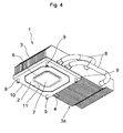
- Fig. 4 is a perspective view showing another exemplary embodiment of a heat sink according to the invention.
- Fig. 5 is a bottom view of the heat sink shown in Fig. 4 ;
- Fig. 6 is an exploded perspective view of the heat sink shown in Fig. 4 .
- the illustrated heat sink 1 comprises a base plate 2 and a plurality of heat radiation fins 3 erected integrally on an upper face of the base plate 2.
- a shape of the base plate 2 may be determined arbitrarily.
- the base plate 2 may be formed into a geometrically refined shape such as a square shape, a rectangular shape or a circular shape. Otherwise, the base plate 2 may also be shaped into an irregular shape such as a star shape.
- the base plate 2 may be a flat heat pipe or a flat vapor chamber.
- the flat heat pipe or vapor chamber is a device for transporting heat comprising an evacuated hollow container, and a condensable working fluid such as water encapsulated in the container.
- a nozzle 4 is shown in the heat pipe or vapor chamber.
- the air is evacuated from the nozzle 4 and the vapor chamber or heat pipe is infused with the working fluid from the nozzle 4.
- a heat receiving portion 6 is formed on a lower face (i.e., a bottom face) of the base plate 2 as a flat heat pipe or vapor chamber.
- an electron device 5 to be cooled is contacted in a heat transmittable manner.
- a contacting area between the heat receiving portion 6 and the electron device 5 is smaller than half the area of the upper face (i.e., the face on which the heat radiation fins 3 are erected) of the base plate 2.
- thermal grease 7 On a top face of the heat receiving portion 6, there is provided thermal grease 7 for facilitating a heat transfer between the heat receiving portion 6 and the electron device 5.
- the thermal grease 7 is prepared by mixing powder having good heat conductivity such as metal powder into the grease, and adhesiveness and heat conductivity between the heat receiving portion 6 and the electron device 5 are thereby improved.
- a plurality of heat radiation fins 3 are erected on the upper face of the base plate 2.
- the heat radiation fins 3 are made of a thin metal plate having good heat conductivity such as aluminum or an aluminum alloy, and soldered integrally with the upper face of the base plate 2 in parallel with each other at regular intervals. That is, the heat radiation fins 3 are erected vertically on the upper face of the base plate 2. Additionally, the heat radiation fins 3 may be integrally fit together by orthogonally bending a predetermined portion thereof such as a lower end portion or a leading end portion, and connecting the adjoining fins.
- Length of the heat radiation fins 3 is longer than the width of the base plate 2. Therefore, an end portion of the heat radiation fins 3 opposite to the end portion fixed to the base plate 2 is extended to protrude significantly from the base plate 2. For this reason, a clearance between an extended portion (i.e., the portion protruding from the base plate 2) 3a of the heat radiation fins 3 is opened not only to the longitudinal direction along the upper face of the base plate 2 but also to the vertical direction with respect to the base plate 2.
- a heat pipe 8 for transporting the heat between the extended portion 3a of the heat radiation fins 3 and the upper face of the base plate 2.
- the heat pipe 8 is a hollow pipe which is bent into U-shape, and which functions as a container. Also, the heat pipe 8 is evacuated and a condensable working fluid such as water is encapsulated therein. That is, the heat pipe 8 is a heat transfer device for transferring heat in the form of latent heat of the working fluid.
- the heat pipes 8 are arranged vertically with respect to the heat radiation fins 3, and intermediate portions of the heat pipes 8 are laterally exposed out of the heat radiation fins 3.
- the other end portions of the heat pipes 8 are inserted into the extended portion 3a of the heat radiation fins 3 from the side face of the heat radiation fins 3, and contacted with the heat radiation fins 3 in a heat transmittable manner. Therefore, the heat is transmitted to the extended portion 3a of the heat radiation fins 3 not only by heat conduction of the heat radiation fins 3 itself but also by the heat pipes 8 directly from the base plate 2.
- standoffs 9 are provided to the base plate 2, shown in Figs. 1 to 3 .
- the electron device 5 which is to be cooled is contacted with the heat receiving portion 6 formed in the lower face of the base plate 2 through the thermal grease 7. Therefore, the heat generated by the electron device 5 is transmitted to around the center of the lower face of the base plate 2 through the thermal grease 7.
- the base plate 2 is a heat pipe or a vapor chamber and the working fluid thereof is vaporized by the heat transmitted from the electron device 5. Since the heat radiation fins 3 and the heat pipes 8 are mounted on the upper face of the base plate 2 so that the temperature thereof is relatively low, the vapor of the working fluid ascends in the base plate 2 to the upper face side, and then contacts with the upper face of the base plate 2.
- the heat is radiated and the vapor of the working fluid is again condensed.
- the heat is transported by the vaporized working fluid in the form of latent heat.
- the heat of the electron device 5 can be transmitted to the heat radiation fins 3 more efficiently in comparison with the case in which a copper whose thermal conductivity is the best is used. That is, the heat can be transported sufficiently to cool the electron device 5.
- the latent heat of the working fluid reaching the upper face of the base plate 2 spreads all over the upper face of the base plate 2, and is then transmitted to the heat radiation fins 3 and the heat pipes 8.
- the heat transmitted to the heat radiation fins 3 propagates all over the heat radiation fins 3, and the heat is diffused into the ambient air. That is, the heat of the electron device 5 is diffused into the air so that the electron device 5 is cooled.
- the heat of the base plate 2 is also transmitted directly to the extended portion 3a of the heat radiation fins 3 by the heat pipe 8. Therefore, the heat is transmitted sufficiently to the portion of the heat radiation fins 3 away from the base plate 2 such as the extended portion 3a.
- clearances between the heat radiation fins 3 are open also to the vertical direction so that the air heated by the heat radiation fins 3 can flow upwardly in the clearance. For this reason, the heat exchange between the heat radiation fins 3 and the air is promoted so that the heat can be radiated efficiently.
- the base plate 2, to which the electron device 5 is attached and which transmits the heat to the heat radiation fins 3, may be a flat heat pipe or vapor chamber. Therefore, the thermal resistance between the electron device 5 and the heat radiation fins 3 can be reduced. Additionally, according to the present invention, an upward flow of the air is generated in the extended portion 3a of the heat radiation fins 3, and the air flows upwardly in the clearance between the heat radiation fins 3. Therefore, it is possible to enhance the heat transfer coefficient and heat exchange amount between the heat radiation fins 3 and the air so that the heat can be radiated efficiently. Consequently, the heat radiation efficiency of the electron device 5 is improved, and the electron device 5 is thereby cooled efficiently.
- the heat sink illustrated in Figs. 4 to 6 comprises a frame 10 which is attached to the lower face (or bottom face) of the base plate 2.
- the frame 10 functions mainly as a reinforce member of the base plate 2. For this reason, base plate 2 of this example is thinner than the base plate 2 of the heat sink shown in Figs. 1 to 3 .
- a contour of the frame 10 is identical to that of the base plate 2, and in the center of the frame 10, there is formed an opening 11 whose outline is similar to that of the heat receiving portion 6 but larger than the heat receiving portion 6.
- the remaining construction of the heat sink 1 illustrated in Figs. 4 to 6 is similar to that in Figs. 1 to 3 , so further description will be omitted by allotting common reference numerals to Figs. 4 to 6 .
- the base plate 2 as a flat heat pipe or vapor chamber has an area two times larger than that of the heat receiving portion 6 to which the electron device 5 is attached. Therefore, the heat of the electron device 5 can be transmitted all over the heat radiation fins 3.
- the heat is also transmitted to the extended portion 3a of the heat radiation fins 3 through the heat pipes 8, the heat radiating area can be substantially enlarged and the heat conductivity of the heat radiation fins 3 itself can be substantially improved.
- an upward flow of the air is generated in the extended portion 3a of the heat radiation fins 3, and the air is allowed to flow upwardly in the clearance between the heat radiation fins 3. For this reason, the heat can be radiated efficiently.
- the heat sink 1 illustrated Figs. 4 to 6 can also radiate the heat of the electron device 5 efficiently so as to cool the electron device 5, as the heat sink 1 illustrated Figs. 1 to 3 .
- the heat sink according to the present invention also has a beneficial effect in case of carrying out a compulsory cooling. Specifically, in case of flowing cooling air from the base plate 2 side by a not shown fan, the air is flown in parallel with the upper face of the base plate 2 between the heat radiation fins 3, and then comes out from between the leading end side of the heat radiation fins 3 extended laterally from a base plate 2 in both forward and vertical directions. The air blowing out downwardly from the leading end 3a of the heat radiation fins 3 will contact with a not shown board to which the electron device 5 is attached. For this reason, the board or a not shown parts attached thereto can be cooled also.
- the number of the heat pipes for transporting the heat to the extended portion 3a of the heat radiation fins 3 is not limited to two pipes but may be one pipe or more than three pipes. Also, it is possible to flatten the end portion of the heat pipe of the base plate side so as to enlarge the contacting area with the base plate. As to the length of the heat radiation fins, it may be around two times longer than the width of the base plate.
- the heat receiving portion is not limited to be situated in the center of the lower face of the base plate as a vapor chamber. The heat receiving portion to which the electron device is contacted may be formed in the portion away from the center of the lower face of the vapor chamber.
Landscapes
- Cooling Or The Like Of Electrical Apparatus (AREA)
- Cooling Or The Like Of Semiconductors Or Solid State Devices (AREA)
Abstract
Description
- This application claims benefit of
U.S. Provisional Application No. 60/911,020 filed April 10, 2007 - 1. Field of the Invention
- The present invention is related to a heat sink for cooling an electron device or electronic device such as an IC (i.e., Integrated Circuit) or an IC chipset by radiating heat thereof into the air.
- 2. Discussion of the Related Art
-
U.S. Patent Nos. 6,102,110 and7,143,819 disclose devices for cooling an electron device by transporting heat generated by the electron device to a portion away from a contact portion of the electron device to radiate the heat therefrom. According to the structure taught byU.S. Patent No. 6,102,110 , one of the end portions of a plurality of heat exchange tubes are secured in a rigid plate, and the other end portion of the heat exchange tubes are protruded from the rigid plate. A plurality of heat radiation fins are mounted on the protruded portion of the heat exchange tubes and electronic power components are attached to the rigid plate. Therefore, heat of the electronic power components are transported to the fins through the heat exchange tubes, and radiated from the fins into the air. - Meanwhile,
U.S. Patent No. 7,143,819 discloses a heat sink, in which an L-shaped or a U-shaped heat pipe provided with heat radiation fins is directly contacted with an electronic component. According to the heat sink suggested byU.S. Patent No. 7,143,819 , heat of the electronic component is transported to the fins through the heat pipe, and radiated from the fins into the air. - Additionally, in the prior art, there is known a heat sink, in which a plurality of heat radiation fins are provided on a top face of a base plate, and a heat receiving portion to be contacted with an electronic component is formed on a bottom face of the base plate.
- However, the heat sink or the radiation device suggested by
U.S. Patent Nos. 6,102,110 and7,143,819 transports the heat of the electron device to the fins by the heat pipe. This means that a large quantity of heat pipes are necessary for those prior art devices. For this reason, such prior art devices have to be dimensionally enlarged and a manufacturing cost thereof also be increased. - As to the aforementioned heat sink of the prior art, in which a plurality of heat radiation fins are provided on a top face of a base plate, the base plate is made of a metal sheet so that the heat capacity thereof is large. This means that thermal resistance between the electron device and the heat radiation fins is large, and this degrades the cooling performance to cool the electron device. Additionally, the heat radiation from the fins is promoted by the air flowing around the fins; however, the direction of the airflow is restricted to the direction in parallel with the top face of the base plate. For this reason, heat radiating efficiency of the heat sink of this kind is not sufficiently high enough.
- Illustrative, non-limiting exemplary embodiments of the present invention overcome the above disadvantages, as well as other disadvantages not described above.
- An object of the present invention is to provide a heat sink capable of cooling an electron device efficiently, by radiating heat of the electron device efficiently into the air. More specifically, an object of the present invention is to provide a heat sink, which has an enlarged substantial heat radiation area, and which allows the air to flow between heat radiation fins in various directions. Another object of the invention is to reduce thermal resistance between the electron device and the heat radiation fins.
- According to the heat sink of the present invention, the heat radiation fins are structured to enhance its heat transporting capability, and the heat pipe is employed as an auxiliary heat transfer means to support mainly a heat radiating portion of the fins. For this purpose, the heat radiating fins are extended laterally from a base plate to which an electron device is attached so as to promote a vertical moving of the air flowing therebetween. In case of natural cooling, for example, ascent of the airflow whose temperature is raised as a result of a heat radiation is promoted. Moreover, in case of carrying out a compulsory cooling using a fan, the air is promoted to flow downwardly and the base plate to which the electron device is contacted is thereby cooled. In order to dissipate the heat more efficiently, the heat pipe is arranged to connect the extended portion of the heat radiation fins and the base plate.
- An apparatus consistent with the heat sink of the present invention comprises a base plate to which an electron device is attached in a heat transmittable manner, and a plurality of heat radiation fins mounted on the base plate. The heat radiation fins are erected vertically and in parallel with each other on the reverse side of the face to which the electron device is contacted. Those heat radiation fins are extended laterally from the base plate, and a heat pipe is provided to transport the heat between the extended portion of the heat radiation fins and the base plate.
- Preferably, the base plate is a vapor chamber comprising a flat hollow container, and a volatilizable and condensable working fluid encapsulated in the container.
- An area of a face of the vapor chamber where the heat radiation fins are erected is preferably more than two times larger than the actual contacting area of the electron device.
- The aforementioned heat pipe is preferably arranged to be contacted with the base plate on the face where the heat radiation fins are erected. It is also preferable to arrange a plurality of heat pipes.
- Additionally, according to the present invention, grease for transferring heat may be interposed between the base plate and the electron device.
- Further, the base plate as the vapor chamber can be thinned by fitting a reinforcement frame therewith. The thermal resistance of the base plate is thereby further lowered, and the heat radiating characteristics is consequently improved.
- These and other features, aspects, and advantages of the present invention will become better understood with reference to the following description and accompanying drawings, which should not be read to limit the invention in any way, in which:
-
Fig. 1 is a perspective view showing an exemplary embodiment of a heat sink according to the invention; -
Fig. 2 is a bottom view of the heat sink shown inFig. 1 ; -
Fig. 3 is an exploded perspective view of the heat sink shown inFig. 1 ; -
Fig. 4 is a perspective view showing another exemplary embodiment of a heat sink according to the invention; -
Fig. 5 is a bottom view of the heat sink shown inFig. 4 ; and -
Fig. 6 is an exploded perspective view of the heat sink shown inFig. 4 . - An exemplary embodiment of the present invention is illustrated in
Figs. 1 to 3 . The illustratedheat sink 1 comprises abase plate 2 and a plurality ofheat radiation fins 3 erected integrally on an upper face of thebase plate 2. A shape of thebase plate 2 may be determined arbitrarily. For example, thebase plate 2 may be formed into a geometrically refined shape such as a square shape, a rectangular shape or a circular shape. Otherwise, thebase plate 2 may also be shaped into an irregular shape such as a star shape. Thebase plate 2 may be a flat heat pipe or a flat vapor chamber. The flat heat pipe or vapor chamber is a device for transporting heat comprising an evacuated hollow container, and a condensable working fluid such as water encapsulated in the container. In the heat pipe or vapor chamber, the heat is transported in the form of latent heat of the working fluid. InFigs. 1 to 3 , anozzle 4 is shown. The air is evacuated from thenozzle 4 and the vapor chamber or heat pipe is infused with the working fluid from thenozzle 4. - A
heat receiving portion 6 is formed on a lower face (i.e., a bottom face) of thebase plate 2 as a flat heat pipe or vapor chamber. To theheat receiving portion 6, anelectron device 5 to be cooled is contacted in a heat transmittable manner. A contacting area between theheat receiving portion 6 and theelectron device 5 is smaller than half the area of the upper face (i.e., the face on which theheat radiation fins 3 are erected) of thebase plate 2. On a top face of theheat receiving portion 6, there is providedthermal grease 7 for facilitating a heat transfer between theheat receiving portion 6 and theelectron device 5. Thethermal grease 7 is prepared by mixing powder having good heat conductivity such as metal powder into the grease, and adhesiveness and heat conductivity between theheat receiving portion 6 and theelectron device 5 are thereby improved. - A plurality of
heat radiation fins 3 are erected on the upper face of thebase plate 2. Theheat radiation fins 3 are made of a thin metal plate having good heat conductivity such as aluminum or an aluminum alloy, and soldered integrally with the upper face of thebase plate 2 in parallel with each other at regular intervals. That is, theheat radiation fins 3 are erected vertically on the upper face of thebase plate 2. Additionally, theheat radiation fins 3 may be integrally fit together by orthogonally bending a predetermined portion thereof such as a lower end portion or a leading end portion, and connecting the adjoining fins. - Length of the
heat radiation fins 3 is longer than the width of thebase plate 2. Therefore, an end portion of theheat radiation fins 3 opposite to the end portion fixed to thebase plate 2 is extended to protrude significantly from thebase plate 2. For this reason, a clearance between an extended portion (i.e., the portion protruding from the base plate 2) 3a of theheat radiation fins 3 is opened not only to the longitudinal direction along the upper face of thebase plate 2 but also to the vertical direction with respect to thebase plate 2. - Further, there is provided a
heat pipe 8 for transporting the heat between theextended portion 3a of theheat radiation fins 3 and the upper face of thebase plate 2. Theheat pipe 8 is a hollow pipe which is bent into U-shape, and which functions as a container. Also, theheat pipe 8 is evacuated and a condensable working fluid such as water is encapsulated therein. That is, theheat pipe 8 is a heat transfer device for transferring heat in the form of latent heat of the working fluid. In the examples illustrated in the accompanying figures, there are provided twoheat pipes 8. One of the end portions of theheat pipes 8 penetrates a lower portion of theheat radiation fins 3, and contacts with the upper face of thebase plate 2. More specifically, theheat pipes 8 are arranged vertically with respect to theheat radiation fins 3, and intermediate portions of theheat pipes 8 are laterally exposed out of theheat radiation fins 3. On the other hand, the other end portions of theheat pipes 8 are inserted into theextended portion 3a of theheat radiation fins 3 from the side face of theheat radiation fins 3, and contacted with theheat radiation fins 3 in a heat transmittable manner. Therefore, the heat is transmitted to theextended portion 3a of theheat radiation fins 3 not only by heat conduction of theheat radiation fins 3 itself but also by theheat pipes 8 directly from thebase plate 2. In addition,standoffs 9 are provided to thebase plate 2, shown inFigs. 1 to 3 . - Next, an operation of the
heat sink 1 will be explained. Theelectron device 5 which is to be cooled is contacted with theheat receiving portion 6 formed in the lower face of thebase plate 2 through thethermal grease 7. Therefore, the heat generated by theelectron device 5 is transmitted to around the center of the lower face of thebase plate 2 through thethermal grease 7. As explained above, thebase plate 2 is a heat pipe or a vapor chamber and the working fluid thereof is vaporized by the heat transmitted from theelectron device 5. Since theheat radiation fins 3 and theheat pipes 8 are mounted on the upper face of thebase plate 2 so that the temperature thereof is relatively low, the vapor of the working fluid ascends in thebase plate 2 to the upper face side, and then contacts with the upper face of thebase plate 2. Consequently, the heat is radiated and the vapor of the working fluid is again condensed. In short, the heat is transported by the vaporized working fluid in the form of latent heat. According to the invention, since the area of the upper face (i.e., the face on which theheat radiation fins 3 are erected) of thebase plate 2 is more than two times larger than the area of the actual contacting area of theelectron device 5, the heat of theelectron device 5 can be transmitted to theheat radiation fins 3 more efficiently in comparison with the case in which a copper whose thermal conductivity is the best is used. That is, the heat can be transported sufficiently to cool theelectron device 5. - The latent heat of the working fluid reaching the upper face of the
base plate 2 spreads all over the upper face of thebase plate 2, and is then transmitted to theheat radiation fins 3 and theheat pipes 8. The heat transmitted to theheat radiation fins 3 propagates all over theheat radiation fins 3, and the heat is diffused into the ambient air. That is, the heat of theelectron device 5 is diffused into the air so that theelectron device 5 is cooled. In addition to the heat conduction of theheat radiation fins 3, the heat of thebase plate 2 is also transmitted directly to theextended portion 3a of theheat radiation fins 3 by theheat pipe 8. Therefore, the heat is transmitted sufficiently to the portion of theheat radiation fins 3 away from thebase plate 2 such as theextended portion 3a. Moreover, in theextended portion 3a, clearances between theheat radiation fins 3 are open also to the vertical direction so that the air heated by theheat radiation fins 3 can flow upwardly in the clearance. For this reason, the heat exchange between theheat radiation fins 3 and the air is promoted so that the heat can be radiated efficiently. - According to the
heat sink 1 of the present invention, thebase plate 2, to which theelectron device 5 is attached and which transmits the heat to theheat radiation fins 3, may be a flat heat pipe or vapor chamber. Therefore, the thermal resistance between theelectron device 5 and theheat radiation fins 3 can be reduced. Additionally, according to the present invention, an upward flow of the air is generated in theextended portion 3a of theheat radiation fins 3, and the air flows upwardly in the clearance between theheat radiation fins 3. Therefore, it is possible to enhance the heat transfer coefficient and heat exchange amount between theheat radiation fins 3 and the air so that the heat can be radiated efficiently. Consequently, the heat radiation efficiency of theelectron device 5 is improved, and theelectron device 5 is thereby cooled efficiently. - Another exemplary embodiment of the present invention will be explained with reference to the accompanying
Figs. 4 to 6 . The heat sink illustrated inFigs. 4 to 6 comprises aframe 10 which is attached to the lower face (or bottom face) of thebase plate 2. Theframe 10 functions mainly as a reinforce member of thebase plate 2. For this reason,base plate 2 of this example is thinner than thebase plate 2 of the heat sink shown inFigs. 1 to 3 . - A contour of the
frame 10 is identical to that of thebase plate 2, and in the center of theframe 10, there is formed anopening 11 whose outline is similar to that of theheat receiving portion 6 but larger than theheat receiving portion 6. The remaining construction of theheat sink 1 illustrated inFigs. 4 to 6 is similar to that inFigs. 1 to 3 , so further description will be omitted by allotting common reference numerals toFigs. 4 to 6 . - In the
heat sink 1 illustrated inFigs. 4 to 6 , thebase plate 2 as a flat heat pipe or vapor chamber has an area two times larger than that of theheat receiving portion 6 to which theelectron device 5 is attached. Therefore, the heat of theelectron device 5 can be transmitted all over theheat radiation fins 3. The heat is also transmitted to theextended portion 3a of theheat radiation fins 3 through theheat pipes 8, the heat radiating area can be substantially enlarged and the heat conductivity of theheat radiation fins 3 itself can be substantially improved. Further, as explained above, an upward flow of the air is generated in theextended portion 3a of theheat radiation fins 3, and the air is allowed to flow upwardly in the clearance between theheat radiation fins 3. For this reason, the heat can be radiated efficiently. Thus, theheat sink 1 illustratedFigs. 4 to 6 can also radiate the heat of theelectron device 5 efficiently so as to cool theelectron device 5, as theheat sink 1 illustratedFigs. 1 to 3 . - Moreover, the heat sink according to the present invention also has a beneficial effect in case of carrying out a compulsory cooling. Specifically, in case of flowing cooling air from the
base plate 2 side by a not shown fan, the air is flown in parallel with the upper face of thebase plate 2 between theheat radiation fins 3, and then comes out from between the leading end side of theheat radiation fins 3 extended laterally from abase plate 2 in both forward and vertical directions. The air blowing out downwardly from theleading end 3a of theheat radiation fins 3 will contact with a not shown board to which theelectron device 5 is attached. For this reason, the board or a not shown parts attached thereto can be cooled also. - Here, the number of the heat pipes for transporting the heat to the
extended portion 3a of theheat radiation fins 3 is not limited to two pipes but may be one pipe or more than three pipes. Also, it is possible to flatten the end portion of the heat pipe of the base plate side so as to enlarge the contacting area with the base plate. As to the length of the heat radiation fins, it may be around two times longer than the width of the base plate. In addition, according to the invention, the heat receiving portion is not limited to be situated in the center of the lower face of the base plate as a vapor chamber. The heat receiving portion to which the electron device is contacted may be formed in the portion away from the center of the lower face of the vapor chamber. - While the present invention has been particularly shown and described with reference to exemplary embodiments thereof, it will be understood by those of ordinary skill in the art that various changes in form and details may be made therein without departing from the spirit and scope of the present invention as defined by the following claims.
Claims (8)
- A heat sink, comprising:a base plate having a heat receiving portion on a lower face to which an electron device is capable of being attached in a heat transmittable manner;a plurality of heat radiation fins mounted on an upper face of the base plate, so as to be erected vertically and in parallel with each other;each of the plurality of heat radiation fins comprising an installed portion mounted on the base plate and an extended portion extending laterally from the base plate; anda heat pipe for transporting heat between the extended portion of the plurality of heat radiation fins and the base plate.
- The heat sink according to claim 1, wherein
the base plate is a vapor chamber comprising:a hollow flat container, anda volatilizable and condensable working fluid encapsulated in the container. - The heat sink according to claim 2, wherein
the upper face of the base plate is more than two times larger than a contacting area of the electron device to the heat receiving portion. - The heat sink according to claim 2, wherein
one end portion of the heat pipe contacts with the upper face of the base plate and penetrates a lower portion of the plurality of heat radiation fins and an other end portion of the heat pipe inserted into the extended portion of the plurality of heat radiation fins. - The heat sink according to claim 2, wherein
a plurality of the heat pipes are provided. - The heat sink according to claim 1, wherein
grease for transferring heat is interposed between the base plate and the electron device. - The heat sink according to claim 1, further comprising
a reinforcement frame to which the base plate is fitted. - The heat sink according to claim 1, wherein a length of the plurality of heat radiation fins is greater than a width of the base plate so that the extended portions of the plurality of heat radiation fins protrude laterally from the base plate.
Applications Claiming Priority (2)
| Application Number | Priority Date | Filing Date | Title |
|---|---|---|---|
| US91102007P | 2007-04-10 | 2007-04-10 | |
| US11/834,738 US7942194B2 (en) | 2007-04-10 | 2007-08-07 | Heat sink |
Publications (2)
| Publication Number | Publication Date |
|---|---|
| EP1981080A2 true EP1981080A2 (en) | 2008-10-15 |
| EP1981080A3 EP1981080A3 (en) | 2011-03-02 |
Family
ID=39473387
Family Applications (1)
| Application Number | Title | Priority Date | Filing Date |
|---|---|---|---|
| EP07021076A Withdrawn EP1981080A3 (en) | 2007-04-10 | 2007-10-29 | Heat sink |
Country Status (3)
| Country | Link |
|---|---|
| US (1) | US7942194B2 (en) |
| EP (1) | EP1981080A3 (en) |
| CN (1) | CN101287350B (en) |
Cited By (1)
| Publication number | Priority date | Publication date | Assignee | Title |
|---|---|---|---|---|
| EP4401130A1 (en) * | 2023-01-12 | 2024-07-17 | Top Rank Technology Limited | Integrated vapor chamber |
Families Citing this family (22)
| Publication number | Priority date | Publication date | Assignee | Title |
|---|---|---|---|---|
| US20090059524A1 (en) * | 2007-08-27 | 2009-03-05 | Fu Zhun Precision Industry (Shen Zhen) Co., Ltd. | Heat dissipation device |
| US20090166006A1 (en) * | 2007-12-27 | 2009-07-02 | Fu Zhun Precision Industry (Shen Zhen) Co., Ltd. | Heat dissipation device |
| US20100101899A1 (en) * | 2008-10-29 | 2010-04-29 | Finkel Brian G | Brake caliper including heat pipes |
| US20110214842A1 (en) * | 2010-03-05 | 2011-09-08 | Lea-Min Technologies Co., Ltd. | Heat sink |
| US20130020055A1 (en) * | 2011-07-19 | 2013-01-24 | Asia Vital Components Co., Ltd. | Thermal module structure and manufacturing method thereof |
| JP5579349B1 (en) * | 2012-12-06 | 2014-08-27 | 古河電気工業株式会社 | heatsink |
| US9772143B2 (en) * | 2013-04-25 | 2017-09-26 | Asia Vital Components Co., Ltd. | Thermal module |
| US9379039B2 (en) * | 2013-09-04 | 2016-06-28 | Cisco Technology, Inc. | Heat transfer for electronic equipment |
| CN104519718A (en) * | 2013-10-08 | 2015-04-15 | 英业达科技有限公司 | Radiating module |
| CN104075604A (en) * | 2014-07-17 | 2014-10-01 | 芜湖长启炉业有限公司 | Superconductor with multiple U-shaped heat pipes in same cavity |
| CN105636405A (en) * | 2014-11-05 | 2016-06-01 | 福特全球技术公司 | Highly integrated power electronic module assembly |
| CN109074852A (en) * | 2016-07-06 | 2018-12-21 | 惠普发展公司,有限责任合伙企业 | Structurally supports the heat sink of the case |
| CN107046794A (en) * | 2017-03-07 | 2017-08-15 | 上海嘉熙科技有限公司 | Hot superconduction gilled radiator and machine box of electric equipment |
| US10809776B2 (en) * | 2018-10-03 | 2020-10-20 | Asia Vital Components (China) Co., Ltd. | Water block mounting holder with reinforced structure |
| JP6733918B2 (en) | 2018-11-13 | 2020-08-05 | Necプラットフォームズ株式会社 | Heat dissipation structure |
| CN109175826B (en) * | 2018-11-27 | 2020-12-29 | 济南山大有色金属铸造有限公司 | Welding device with heat dissipation structure for aluminum product machining |
| US11092383B2 (en) * | 2019-01-18 | 2021-08-17 | Asia Vital Components Co., Ltd. | Heat dissipation device |
| JP7012674B2 (en) * | 2019-01-27 | 2022-02-14 | Hoya株式会社 | Heat dissipation device and light irradiation device equipped with it |
| TWI718485B (en) * | 2019-02-27 | 2021-02-11 | 雙鴻科技股份有限公司 | Heat exchange device |
| CN121968441A (en) * | 2020-03-27 | 2026-05-01 | 索尼互动娱乐股份有限公司 | Heat dissipating device and electronic equipment |
| TWI824401B (en) * | 2022-01-28 | 2023-12-01 | 奇鋐科技股份有限公司 | Heat dissipation device assembly |
| TWI815294B (en) * | 2022-01-28 | 2023-09-11 | 奇鋐科技股份有限公司 | Thermal module structure |
Family Cites Families (35)
| Publication number | Priority date | Publication date | Assignee | Title |
|---|---|---|---|---|
| US4633371A (en) * | 1984-09-17 | 1986-12-30 | Amdahl Corporation | Heat pipe heat exchanger for large scale integrated circuits |
| FR2773941B1 (en) | 1998-01-19 | 2000-04-21 | Ferraz | DI-PHASIC EXCHANGER FOR AT LEAST ONE ELECTRONIC POWER COMPONENT |
| JP2001024374A (en) | 1999-07-09 | 2001-01-26 | Furukawa Electric Co Ltd:The | High heat density heat sink for heating element |
| CN1305131C (en) * | 2000-11-20 | 2007-03-14 | 英特尔公司 | High performance heat sink configurations for use in high density packaging applications |
| TW520146U (en) * | 2002-06-13 | 2003-02-01 | Hon Hai Prec Ind Co Ltd | Heat pipe assembly |
| US7143819B2 (en) | 2002-09-17 | 2006-12-05 | Hewlett-Packard Development Company, L.P. | Heat sink with angled heat pipe |
| US6894900B2 (en) * | 2002-09-17 | 2005-05-17 | Hewlett-Packard Development Company, L.P. | Heat sink with heat pipe and base fins |
| US7140422B2 (en) * | 2002-09-17 | 2006-11-28 | Hewlett-Packard Development Company, L.P. | Heat sink with heat pipe in direct contact with component |
| TW557350B (en) * | 2003-01-06 | 2003-10-11 | Jiun-Guang Luo | One-way airstream hollow cavity energy transferring device |
| US6938680B2 (en) * | 2003-07-14 | 2005-09-06 | Thermal Corp. | Tower heat sink with sintered grooved wick |
| CN2664184Y (en) * | 2003-11-17 | 2004-12-15 | 鸿富锦精密工业(深圳)有限公司 | Heat sink |
| TW200537278A (en) * | 2004-05-13 | 2005-11-16 | Mitac Technology Corp | Fin heat sink module having a tail air-guiding section |
| US20050274487A1 (en) * | 2004-05-27 | 2005-12-15 | International Business Machines Corporation | Method and apparatus for reducing thermal resistance in a vertical heat sink assembly |
| US7353860B2 (en) * | 2004-06-16 | 2008-04-08 | Intel Corporation | Heat dissipating device with enhanced boiling/condensation structure |
| US7128135B2 (en) * | 2004-11-12 | 2006-10-31 | International Business Machines Corporation | Cooling device using multiple fans and heat sinks |
| CN2842729Y (en) | 2004-11-16 | 2006-11-29 | 黄註财 | Fan-shaped heat sink structure of heat pipe ring radiator |
| US20060102325A1 (en) * | 2004-11-17 | 2006-05-18 | Detech Technology Co., Ltd. | Guiding fin heat sink |
| CN100351602C (en) | 2004-11-29 | 2007-11-28 | 杨洪武 | Foil sheet groove liquid sucking core of heat pipe radiator |
| US7246655B2 (en) * | 2004-12-17 | 2007-07-24 | Fujikura Ltd. | Heat transfer device |
| CN2775837Y (en) | 2005-02-23 | 2006-04-26 | 林项武 | Aluminum-copper combined integrated circuit heat radiator using heat pipe technology |
| US7089999B1 (en) * | 2005-03-10 | 2006-08-15 | Chaun-Choung Technology Corp. | Hood retaining structure for heat-dissipating device |
| TWI274539B (en) * | 2005-04-01 | 2007-02-21 | Delta Electronics Inc | Heat dissipating assembly with composite heat dissipating structure |
| TWI311363B (en) * | 2005-04-22 | 2009-06-21 | Foxconn Tech Co Ltd | Boiling chamber cooling device |
| US7143816B1 (en) * | 2005-09-09 | 2006-12-05 | Delphi Technologies, Inc. | Heat sink for an electronic device |
| US7036566B1 (en) * | 2005-10-06 | 2006-05-02 | Tsung-Hsien Huang | Heat dissipating module |
| USD541757S1 (en) * | 2005-12-19 | 2007-05-01 | Zalman Tech Co., Ltd. | Radiator for electronic parts |
| US7269013B2 (en) * | 2006-01-09 | 2007-09-11 | Fu Zhun Prexision Industry (Shan Zhen) Co., Ltd. | Heat dissipation device having phase-changeable medium therein |
| US20070277958A1 (en) * | 2006-06-01 | 2007-12-06 | Yi-He Huang | Heat Dissipator |
| CN100499981C (en) | 2006-06-30 | 2009-06-10 | 富准精密工业(深圳)有限公司 | Heat pipe radiator |
| US20080128118A1 (en) * | 2006-12-01 | 2008-06-05 | Foxconn Technology Co., Ltd. | Heat dissipation device with a heat pipe |
| TWD119775S1 (en) * | 2006-12-08 | 2007-11-01 | 曜越科技股份有限公司 | Radiator (VII) |
| USD576963S1 (en) * | 2007-01-30 | 2008-09-16 | Fujikura Ltd. | Heat sink |
| US20080310105A1 (en) * | 2007-06-14 | 2008-12-18 | Chia-Chun Cheng | Heat dissipating apparatus and water cooling system having the same |
| USD593511S1 (en) * | 2008-07-18 | 2009-06-02 | Foxconn Technology Co., Ltd. | Heat dissipation device |
| USD597498S1 (en) * | 2008-07-18 | 2009-08-04 | Foxconn Technology Co., Ltd. | Heat dissipation device |
-
2007
- 2007-08-07 US US11/834,738 patent/US7942194B2/en not_active Expired - Fee Related
- 2007-10-29 EP EP07021076A patent/EP1981080A3/en not_active Withdrawn
- 2007-11-30 CN CN200710195494.3A patent/CN101287350B/en not_active Expired - Fee Related
Cited By (1)
| Publication number | Priority date | Publication date | Assignee | Title |
|---|---|---|---|---|
| EP4401130A1 (en) * | 2023-01-12 | 2024-07-17 | Top Rank Technology Limited | Integrated vapor chamber |
Also Published As
| Publication number | Publication date |
|---|---|
| US20080251239A1 (en) | 2008-10-16 |
| EP1981080A3 (en) | 2011-03-02 |
| CN101287350B (en) | 2010-12-08 |
| CN101287350A (en) | 2008-10-15 |
| US7942194B2 (en) | 2011-05-17 |
Similar Documents
| Publication | Publication Date | Title |
|---|---|---|
| US7942194B2 (en) | Heat sink | |
| JP5249434B2 (en) | Servo amplifier with heat sink for heat dissipation having two sets of heat dissipation fins orthogonal to each other | |
| US6626233B1 (en) | Bi-level heat sink | |
| US20070234741A1 (en) | Heat radiator having a thermo-electric cooler and multiple heat radiation modules and the method of the same | |
| JP5228115B2 (en) | heatsink | |
| US7926553B2 (en) | Cooling system for electronic devices, in particular, computers | |
| US7766074B2 (en) | Heat-dissipating device having air-guiding structure | |
| US8496047B2 (en) | Heat dissipating apparatus extended laterally from heat pipe | |
| US20120217630A1 (en) | Heatsink, heatsink assembly, semiconductor module, and semiconductor device with cooling device | |
| CN100437997C (en) | Cooling Units and Electronics | |
| CN111384011A (en) | Heat dissipation device and method | |
| US8579017B2 (en) | Heat dissipation device with multiple heat sinks | |
| JP4728522B2 (en) | heatsink | |
| JP2005229102A (en) | heatsink | |
| JP7355903B1 (en) | heat sink | |
| WO1999053256A1 (en) | Plate type heat pipe and its installation structure | |
| JP3819316B2 (en) | Tower type heat sink | |
| JP5624771B2 (en) | Heat pipe and heat sink with heat pipe | |
| JP2003198171A (en) | Heat sinks and radiators | |
| JP2001060788A (en) | Flat type good heat transfer type heat sink | |
| TWI403257B (en) | Heat sink | |
| CN100592850C (en) | heat pipe radiator | |
| CN208821147U (en) | Microchannel heat sink | |
| JP2009224664A (en) | Heat radiating structure | |
| JP2007208154A (en) | Cooling device for electronic equipment |
Legal Events
| Date | Code | Title | Description |
|---|---|---|---|
| PUAI | Public reference made under article 153(3) epc to a published international application that has entered the european phase |
Free format text: ORIGINAL CODE: 0009012 |
|
| 17P | Request for examination filed |
Effective date: 20071129 |
|
| AK | Designated contracting states |
Kind code of ref document: A2 Designated state(s): AT BE BG CH CY CZ DE DK EE ES FI FR GB GR HU IE IS IT LI LT LU LV MC MT NL PL PT RO SE SI SK TR |
|
| AX | Request for extension of the european patent |
Extension state: AL BA HR MK RS |
|
| PUAL | Search report despatched |
Free format text: ORIGINAL CODE: 0009013 |
|
| AK | Designated contracting states |
Kind code of ref document: A3 Designated state(s): AT BE BG CH CY CZ DE DK EE ES FI FR GB GR HU IE IS IT LI LT LU LV MC MT NL PL PT RO SE SI SK TR |
|
| AX | Request for extension of the european patent |
Extension state: AL BA HR MK RS |
|
| AKX | Designation fees paid |
Designated state(s): FR GB |
|
| REG | Reference to a national code |
Ref country code: DE Ref legal event code: R108 |
|
| REG | Reference to a national code |
Ref country code: DE Ref legal event code: R108 Effective date: 20111109 |
|
| 17Q | First examination report despatched |
Effective date: 20111213 |
|
| STAA | Information on the status of an ep patent application or granted ep patent |
Free format text: STATUS: THE APPLICATION IS DEEMED TO BE WITHDRAWN |
|
| 18D | Application deemed to be withdrawn |
Effective date: 20120424 |