EP1980804A2 - Verfahren zur Bereitstellung von thermischer Energie - Google Patents
Verfahren zur Bereitstellung von thermischer Energie Download PDFInfo
- Publication number
- EP1980804A2 EP1980804A2 EP08102719A EP08102719A EP1980804A2 EP 1980804 A2 EP1980804 A2 EP 1980804A2 EP 08102719 A EP08102719 A EP 08102719A EP 08102719 A EP08102719 A EP 08102719A EP 1980804 A2 EP1980804 A2 EP 1980804A2
- Authority
- EP
- European Patent Office
- Prior art keywords
- heat
- heat pump
- gas engine
- solar absorber
- condenser
- Prior art date
- Legal status (The legal status is an assumption and is not a legal conclusion. Google has not performed a legal analysis and makes no representation as to the accuracy of the status listed.)
- Granted
Links
- 238000000034 method Methods 0.000 title claims abstract description 11
- 239000006096 absorbing agent Substances 0.000 claims description 37
- 239000007789 gas Substances 0.000 claims description 33
- 238000010438 heat treatment Methods 0.000 claims description 15
- XLYOFNOQVPJJNP-UHFFFAOYSA-N water Substances O XLYOFNOQVPJJNP-UHFFFAOYSA-N 0.000 claims description 9
- 230000009182 swimming Effects 0.000 claims description 8
- 238000001816 cooling Methods 0.000 claims description 7
- 239000002918 waste heat Substances 0.000 claims description 5
- 238000002360 preparation method Methods 0.000 claims description 4
- 230000005855 radiation Effects 0.000 description 6
- 230000002349 favourable effect Effects 0.000 description 3
- 230000008878 coupling Effects 0.000 description 2
- 238000010168 coupling process Methods 0.000 description 2
- 238000005859 coupling reaction Methods 0.000 description 2
- 239000000446 fuel Substances 0.000 description 2
- 101100165177 Caenorhabditis elegans bath-15 gene Proteins 0.000 description 1
- 230000009286 beneficial effect Effects 0.000 description 1
- 230000015572 biosynthetic process Effects 0.000 description 1
- 238000004891 communication Methods 0.000 description 1
- 238000010586 diagram Methods 0.000 description 1
- 238000005265 energy consumption Methods 0.000 description 1
- 238000009472 formulation Methods 0.000 description 1
- 239000011521 glass Substances 0.000 description 1
- 238000009434 installation Methods 0.000 description 1
- 239000000203 mixture Substances 0.000 description 1
- 238000005057 refrigeration Methods 0.000 description 1
- 238000003303 reheating Methods 0.000 description 1
Images
Classifications
-
- F—MECHANICAL ENGINEERING; LIGHTING; HEATING; WEAPONS; BLASTING
- F24—HEATING; RANGES; VENTILATING
- F24D—DOMESTIC- OR SPACE-HEATING SYSTEMS, e.g. CENTRAL HEATING SYSTEMS; DOMESTIC HOT-WATER SUPPLY SYSTEMS; ELEMENTS OR COMPONENTS THEREFOR
- F24D3/00—Hot-water central heating systems
- F24D3/18—Hot-water central heating systems using heat pumps
-
- F—MECHANICAL ENGINEERING; LIGHTING; HEATING; WEAPONS; BLASTING
- F24—HEATING; RANGES; VENTILATING
- F24D—DOMESTIC- OR SPACE-HEATING SYSTEMS, e.g. CENTRAL HEATING SYSTEMS; DOMESTIC HOT-WATER SUPPLY SYSTEMS; ELEMENTS OR COMPONENTS THEREFOR
- F24D2200/00—Heat sources or energy sources
- F24D2200/12—Heat pump
-
- F—MECHANICAL ENGINEERING; LIGHTING; HEATING; WEAPONS; BLASTING
- F24—HEATING; RANGES; VENTILATING
- F24D—DOMESTIC- OR SPACE-HEATING SYSTEMS, e.g. CENTRAL HEATING SYSTEMS; DOMESTIC HOT-WATER SUPPLY SYSTEMS; ELEMENTS OR COMPONENTS THEREFOR
- F24D2200/00—Heat sources or energy sources
- F24D2200/14—Solar energy
-
- F—MECHANICAL ENGINEERING; LIGHTING; HEATING; WEAPONS; BLASTING
- F24—HEATING; RANGES; VENTILATING
- F24D—DOMESTIC- OR SPACE-HEATING SYSTEMS, e.g. CENTRAL HEATING SYSTEMS; DOMESTIC HOT-WATER SUPPLY SYSTEMS; ELEMENTS OR COMPONENTS THEREFOR
- F24D2200/00—Heat sources or energy sources
- F24D2200/16—Waste heat
- F24D2200/26—Internal combustion engine
-
- F—MECHANICAL ENGINEERING; LIGHTING; HEATING; WEAPONS; BLASTING
- F25—REFRIGERATION OR COOLING; COMBINED HEATING AND REFRIGERATION SYSTEMS; HEAT PUMP SYSTEMS; MANUFACTURE OR STORAGE OF ICE; LIQUEFACTION SOLIDIFICATION OF GASES
- F25B—REFRIGERATION MACHINES, PLANTS OR SYSTEMS; COMBINED HEATING AND REFRIGERATION SYSTEMS; HEAT PUMP SYSTEMS
- F25B27/00—Machines, plants or systems, using particular sources of energy
- F25B27/002—Machines, plants or systems, using particular sources of energy using solar energy
- F25B27/005—Machines, plants or systems, using particular sources of energy using solar energy in compression type systems
-
- F—MECHANICAL ENGINEERING; LIGHTING; HEATING; WEAPONS; BLASTING
- F25—REFRIGERATION OR COOLING; COMBINED HEATING AND REFRIGERATION SYSTEMS; HEAT PUMP SYSTEMS; MANUFACTURE OR STORAGE OF ICE; LIQUEFACTION SOLIDIFICATION OF GASES
- F25B—REFRIGERATION MACHINES, PLANTS OR SYSTEMS; COMBINED HEATING AND REFRIGERATION SYSTEMS; HEAT PUMP SYSTEMS
- F25B27/00—Machines, plants or systems, using particular sources of energy
- F25B27/02—Machines, plants or systems, using particular sources of energy using waste heat, e.g. from internal-combustion engines
-
- Y—GENERAL TAGGING OF NEW TECHNOLOGICAL DEVELOPMENTS; GENERAL TAGGING OF CROSS-SECTIONAL TECHNOLOGIES SPANNING OVER SEVERAL SECTIONS OF THE IPC; TECHNICAL SUBJECTS COVERED BY FORMER USPC CROSS-REFERENCE ART COLLECTIONS [XRACs] AND DIGESTS
- Y02—TECHNOLOGIES OR APPLICATIONS FOR MITIGATION OR ADAPTATION AGAINST CLIMATE CHANGE
- Y02A—TECHNOLOGIES FOR ADAPTATION TO CLIMATE CHANGE
- Y02A30/00—Adapting or protecting infrastructure or their operation
- Y02A30/27—Relating to heating, ventilation or air conditioning [HVAC] technologies
- Y02A30/274—Relating to heating, ventilation or air conditioning [HVAC] technologies using waste energy, e.g. from internal combustion engine
-
- Y—GENERAL TAGGING OF NEW TECHNOLOGICAL DEVELOPMENTS; GENERAL TAGGING OF CROSS-SECTIONAL TECHNOLOGIES SPANNING OVER SEVERAL SECTIONS OF THE IPC; TECHNICAL SUBJECTS COVERED BY FORMER USPC CROSS-REFERENCE ART COLLECTIONS [XRACs] AND DIGESTS
- Y02—TECHNOLOGIES OR APPLICATIONS FOR MITIGATION OR ADAPTATION AGAINST CLIMATE CHANGE
- Y02A—TECHNOLOGIES FOR ADAPTATION TO CLIMATE CHANGE
- Y02A40/00—Adaptation technologies in agriculture, forestry, livestock or agroalimentary production
- Y02A40/90—Adaptation technologies in agriculture, forestry, livestock or agroalimentary production in food processing or handling, e.g. food conservation
- Y02A40/963—Off-grid food refrigeration
-
- Y—GENERAL TAGGING OF NEW TECHNOLOGICAL DEVELOPMENTS; GENERAL TAGGING OF CROSS-SECTIONAL TECHNOLOGIES SPANNING OVER SEVERAL SECTIONS OF THE IPC; TECHNICAL SUBJECTS COVERED BY FORMER USPC CROSS-REFERENCE ART COLLECTIONS [XRACs] AND DIGESTS
- Y02—TECHNOLOGIES OR APPLICATIONS FOR MITIGATION OR ADAPTATION AGAINST CLIMATE CHANGE
- Y02B—CLIMATE CHANGE MITIGATION TECHNOLOGIES RELATED TO BUILDINGS, e.g. HOUSING, HOUSE APPLIANCES OR RELATED END-USER APPLICATIONS
- Y02B10/00—Integration of renewable energy sources in buildings
- Y02B10/20—Solar thermal
-
- Y—GENERAL TAGGING OF NEW TECHNOLOGICAL DEVELOPMENTS; GENERAL TAGGING OF CROSS-SECTIONAL TECHNOLOGIES SPANNING OVER SEVERAL SECTIONS OF THE IPC; TECHNICAL SUBJECTS COVERED BY FORMER USPC CROSS-REFERENCE ART COLLECTIONS [XRACs] AND DIGESTS
- Y02—TECHNOLOGIES OR APPLICATIONS FOR MITIGATION OR ADAPTATION AGAINST CLIMATE CHANGE
- Y02B—CLIMATE CHANGE MITIGATION TECHNOLOGIES RELATED TO BUILDINGS, e.g. HOUSING, HOUSE APPLIANCES OR RELATED END-USER APPLICATIONS
- Y02B10/00—Integration of renewable energy sources in buildings
- Y02B10/70—Hybrid systems, e.g. uninterruptible or back-up power supplies integrating renewable energies
-
- Y—GENERAL TAGGING OF NEW TECHNOLOGICAL DEVELOPMENTS; GENERAL TAGGING OF CROSS-SECTIONAL TECHNOLOGIES SPANNING OVER SEVERAL SECTIONS OF THE IPC; TECHNICAL SUBJECTS COVERED BY FORMER USPC CROSS-REFERENCE ART COLLECTIONS [XRACs] AND DIGESTS
- Y02—TECHNOLOGIES OR APPLICATIONS FOR MITIGATION OR ADAPTATION AGAINST CLIMATE CHANGE
- Y02B—CLIMATE CHANGE MITIGATION TECHNOLOGIES RELATED TO BUILDINGS, e.g. HOUSING, HOUSE APPLIANCES OR RELATED END-USER APPLICATIONS
- Y02B30/00—Energy efficient heating, ventilation or air conditioning [HVAC]
- Y02B30/12—Hot water central heating systems using heat pumps
-
- Y—GENERAL TAGGING OF NEW TECHNOLOGICAL DEVELOPMENTS; GENERAL TAGGING OF CROSS-SECTIONAL TECHNOLOGIES SPANNING OVER SEVERAL SECTIONS OF THE IPC; TECHNICAL SUBJECTS COVERED BY FORMER USPC CROSS-REFERENCE ART COLLECTIONS [XRACs] AND DIGESTS
- Y02—TECHNOLOGIES OR APPLICATIONS FOR MITIGATION OR ADAPTATION AGAINST CLIMATE CHANGE
- Y02B—CLIMATE CHANGE MITIGATION TECHNOLOGIES RELATED TO BUILDINGS, e.g. HOUSING, HOUSE APPLIANCES OR RELATED END-USER APPLICATIONS
- Y02B30/00—Energy efficient heating, ventilation or air conditioning [HVAC]
- Y02B30/52—Heat recovery pumps, i.e. heat pump based systems or units able to transfer the thermal energy from one area of the premises or part of the facilities to a different one, improving the overall efficiency
Definitions
- the present invention relates to a method according to the preamble of claim 1.
- the shows CN 1 869 553 A a system with gas engine, heat pump and solar absorber, in which the heat generated in the solar absorber can be fed into the evaporator circuit of the heat on the one hand, or on the other hand can be routed to the consumers.
- a parallel connection of the heat pump cycle and the solar cycle is given in a heat exchanger.
- the solar absorber it is possible within the scope of the invention to form the solar absorber as a skating rink, that is to say that this component is deprived of so much heat that an ice surface can be built up.
- the heat generated in the solar absorber at comparatively high temperatures must be optimally utilized.
- a further object of the present invention is to develop a method of the type described above so that the fuel consumption substantially can be limited, with as far as possible regulation should be achievable.
- a particular object of the present invention is to provide a method which optimally combines various requirements, such as provision of heating heat, hot water heating and heating of a swimming pool.
- Another object of the present invention is to provide an apparatus for carrying out such a method.
- the essential feature of the present invention is that the solar absorber is not or not only used in parallel to the heat pump, but that it is also possible with the method according to the invention to raise the temperature level of the heat provided at the solar absorber according to an optimal supply of different consumer groups achieve.
- the solution according to the invention makes it possible in particular to lead a portion of the amount of heat from the solar absorber through the heat pump cycle, but at the same time deliver a portion of the heat directly to the actual consumers via the heat exchanger. In this way, the efficiency can be further increased.
- solar absorber a solar absorber, which is designed essentially as an exposed hose system.
- high-performance absorbers have a glass cover, which makes it possible to increase the efficiency of solar radiation, since the thermal radiation is reduced.
- this disadvantage is deliberately accepted because in this way a significantly improved heat transfer is achieved when there is little or no solar radiation.
- the medium heated by the solar absorber is guided in a first bypass system as a function of the temperature level of the solar circuit to the condenser of the heat pump. In this way, you can achieve that with appropriate heat supply to the solar absorber this is connectable to the corresponding consumers.
- the heat transfer medium can be performed either directly to the consumers or via the condenser of the heat pump to an additional reheating. If, in this context, it is said that the medium heated by the solar absorber is led to a certain point, then this should also include the case in which a heat exchanger is interposed. This also applies to analogous formulations in the sequence.
- waste heat of the gas engine and the heat at the condenser of the heat pump is supplied to different consumption groups.
- different temperature levels can be exploited in an optimal manner and it is much easier to control the system.
- the waste heat of the gas engine is supplied to a heating and hot water preparation system, while the heat generated at the condenser heat is supplied to a swimming pool. The losses can be reduced in this way, since the temperature level at the gas engine is usually higher than that at the heat pump, at least when trying to operate in an energetically favorable operating condition.
- the present invention relates to a device for providing thermal energy with a gas engine, which drives a heat pump, and with means for transmitting the heat generated by the gas engine and the heat generated at the evaporator of the heat pump to consumers.
- a solar absorber is provided, which is in communication with the evaporator circuit of the heat pump.
- the energy accumulating on the solar absorber can optimally be used by a bypass system connecting the solar absorber to the heat pump's condenser.
- the thermal energy accumulating on the gas engine can be utilized in a particularly advantageous manner by providing an exhaust gas bypass valve which regulates the temperature level of an exhaust gas circuit of the gas engine.
- a cooling circuit bypass valve is provided which regulates the temperature level of the cooling circuit of the gas engine.
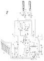
- the figure shows a circuit diagram of a system designed according to the invention.
- the plant consists of a solar absorber 1, which is connected via a first line system 10 with a heat pump unit, which is designated overall by 3.
- the heat pump unit 3 consists of the actual heat pump 2 and a gas engine 4, which drives the compressor 5 of the heat pump 2.
- the cycle of the heat pump 2 further consists of a condenser 6, an expansion valve 7 and an evaporator 8.
- the evaporator 8 communicates with the first conduit system 10, which leads to the solar absorber 1, in connection.
- a pump 30 serves to convey the medium in the solar circuit.
- the solar absorber may optionally be associated with a first heat exchanger 13 which is part of a first bypass system, generally designated 14.
- This bypass system is initially connected to the condenser 6 of the heat pump 2 in connection and subsequently leads to consumers, namely an outdoor pool 15 and an indoor pool 16.
- the gas engine 4 is divided in the figure schematically into an exhaust part 4a and a cooling circuit part 4b. This means that, on the one hand, heat is obtained from the cooling circuit 4b and, on the other hand, from the exhaust system 4a of the gas engine 4.
- the heat from these systems is discharged via pumps 17, 18 and mixing valves, which are designed as exhaust valve 19 and as a cooling circuit bypass valve 20.
- the heat is supplied via a fourth heat exchanger 22 and a fifth heat exchanger 23 to a schematically indicated heating system 24 and a water heating system 25.
- a further mixing valve 26 and a third heat exchanger 27, depending on the temperature level heat can be transferred between the system for heating the outdoor bath 15 and the indoor pool 16 and the system for heating and hot water preparation.
- Another pump 28 serves to convey the medium in the bypass system 14.
- a generator 31 is further connected to generate electrical energy. About appropriate couplings, or controls a flexible circuit is achieved, so that the gas engine either only to generate can be used by electrical energy via the generator 31 or only to operate the compressor 5 or simultaneously for both purposes.
- the present invention is also designed for refrigeration.
- the solar absorber circuit is decoupled via valves 32, 33, 34, 35 and by the pump 36, a heat exchanger is fed, which supplies a cold storage tank 39 via a pump 37.
- the heat demand for heat in the swimming pools 15, 16 is greater than can be provided by the heat pump 2, and on the other hand, the heat demand for heating hot water is not excessive, so can heat through the third heat exchanger 27 in addition to the gas engine. 4 be diverted to the swimming pool heating, which can be controlled via the mixing valve 26. Conversely, with little need for heat for the swimming pools 15, 16 can come to a return of heat from the heat pump 2 in the heating and hot water system.
- appropriate temperature sensor which are not shown in the figure, together with a control, also not shown, an optimal operation of the system can be ensured.
- part of the resulting heat can be dissipated via the first heat exchanger 13 and led directly to the condenser 6 of the heat pump 2. In this way, the heat pump 2 is relieved and reduced energy consumption.
- the temperature level at the solar absorber 1 can be lowered by the evaporator 8 of the heat pump 2 so far that ice formation occurs, whereby the establishment of skating rinks is possible.
- the present invention makes it possible to ensure an optimal use of primary energy together with the use of solar energy. In doing so, a particularly broad spectrum of requirements can be covered.
Landscapes
- Engineering & Computer Science (AREA)
- Physics & Mathematics (AREA)
- Thermal Sciences (AREA)
- Chemical & Material Sciences (AREA)
- Combustion & Propulsion (AREA)
- Mechanical Engineering (AREA)
- General Engineering & Computer Science (AREA)
- Heat-Pump Type And Storage Water Heaters (AREA)
- Sorption Type Refrigeration Machines (AREA)
- Engine Equipment That Uses Special Cycles (AREA)
Abstract
Description
- Die vorliegende Erfindung betrifft ein Verfahren gemäß dem Oberbegriff von Patentanspruch 1.
- Aus der
US 6,735,696 A ist es bekannt, einen Gasmotor zum Antrieb einer Wärmepumpe zu nutzen, wobei gleichzeitig die am Gasmotor selbst anfallende Wärme mitgenutzt wird. Damit ist es zwar möglich, die bereitgestellte Wärmemenge deutlich über die Wärmemenge zu steigern, die dem Brennwert des eingesetzten Kraftstoffes entspricht, die Effizienz des Systems ist jedoch im Vergleich zum notwendigen Aufwand unbefriedigend. Insbesondere sind die Regelungsmöglichkeiten einer solchen Anlage beschränkt. - Weiters zeigt die
CN 1 869 553 A ein System mit Gasmotor, Wärmepumpe und Solarabsorber, bei der die im Solarabsorber erzeugte Wärme einerseits in den Verdampferkreislauf der Wärme eingespeist oder andererseits zu den Verbrauchern geleitet werden kann. Dabei ist in einem Wärmetauscher eine Parallelschaltung des Wärmepumpenkreislaufes und des Solarkreislaufes gegeben. - Es ist eine Aufgabe der Erfindung, die Möglichkeit zu schaffen, dass auch dann ein sinnvoller Betrieb möglich ist, wenn der Solarabsorber unter Umgebungstemperatur abgekühlt wird. Es ist zum Beispiel im Rahmen der Erfindung möglich, den Solarabsorber als Eislaufplatz auszubilden, d.h., dass diesem Bauteil soviel Wärme entzogen wird, dass eine Eisfläche aufgebaut werden kann. In einem Sommerbetrieb muss andererseits die im Solarabsorber bei vergleichsweise hohen Temperaturen anfallende Wärme optimal genützt werden. Neben diesen Betriebszuständen gibt es aber auch Betriebszustände, bei denen die Sonneneinstrahlung vorhanden aber schwach ist oder bei denen bei gegebener Sonneneinstrahlung aber sehr niedrigen Außentemperaturen im Solarabsorber nicht ausreichend hohe Temperaturen erreicht werden können, um die Verbraucher direkt anzuspeisen. Bei der aus dem oben genannten Dokument bekannten Lösung ist es in einem solchen Betriebszustand erforderlich, die gesamte Wärmemenge des Solarabsorbers über den Wärmepumpenkreislauf zu führen.
- Eine weitere Aufgabe der vorliegenden Erfindung ist es, ein Verfahren der oben beschriebenen Art so weiterzubilden, dass der Kraftstoffverbrauch wesentlich eingeschränkt werden kann, wobei eine möglichst weitgehende Regelung erreichbar sein soll. Eine besondere Aufgabe der vorliegenden Erfindung ist es, ein Verfahren anzugeben, das verschiedene Anforderungen, wie Bereitstellung von Heizungswärme, Warmwassererwärmung und Erwärmung eines Schwimmbades, in optimaler Weise kombiniert. Eine weitere Aufgabe der vorliegenden Erfindung ist es, eine Vorrichtung zur Durchführung eines solchen Verfahrens anzugeben.
- Erfindungsgemäß werden diese Aufgaben durch die Merkmale von Patentanspruch 1 gelöst. Wesentlich an der vorliegenden Erfindung ist, dass der Solarabsorber nicht bzw. nicht nur parallel zur Wärmepumpe eingesetzt wird, sondern dass es mit dem erfindungsgemäßen Verfahren auch möglich ist, das Temperaturniveau der am Solarabsorber bereitgestellten Wärme entsprechend anzuheben, um eine optimale Anspeisung der verschiedenen Verbrauchergruppen zu erzielen. Dabei ermöglicht es die erfindungsgemäße Lösung insbesondere, einen Teil der Wärmemenge aus dem Solarabsorber über den Wärmepumpenkreislauf zu führen, gleichzeitig jedoch über den Wärmetauscher einen Teil der Wärme direkt an die eigentlichen Verbraucher abzugeben. Auf diese Weise kann der Wirkungsgrad weiter erhöht werden.
- Im gegebenen Zusammenhang ist mit Solarabsorber ein Solarabsorber gemeint, der im Wesentlichen als frei liegendes Schlauchsystem ausgebildet ist. Im Gegensatz dazu besitzen Hochleistungsabsorber eine Abdeckung aus Glas, was es ermöglicht, bei Sonneneinstrahlung den Wirkungsgrad zu erhöhen, da die thermische Abstrahlung vermindert wird. Bei den Solarabsorbern der vorliegenden Erfindung wird dieser Nachteil bewusst in Kauf genommen, da auf diese Weise ein wesentlich verbesserter Wärmeübergang erzielt wird, wenn keine oder nur geringe Sonneneinstrahlung vorliegt. Darüber hinaus ist es in in einfacher Weise möglich, die Solarabsorber begehbar auszugestalten und als Nutzfläche wie etwa als Eislaufplatz zu verwenden.
- Besonders günstig ist es, wenn das vom Solarabsorber erwärmte Medium in einem ersten Bypasssystem in Abhängigkeit vom Temperaturniveau des Solarkreises zum Kondensator der Wärmepumpe geführt wird. Auf diese Weise kann man erreichen, dass bei entsprechendem Wärmeangebot am Solarabsorber dieser mit den entsprechenden Verbrauchern verbindbar ist. Dabei kann das Wärmeträgermedium entweder direkt zu den Verbrauchern oder über den Kondensator der Wärmepumpe zu einer zusätzlichen Nacherwärmung geführt werden. Wenn in diesem Zusammenhang davon die Rede ist, dass das vom Solarabsorber erwärmte Medium zu einem bestimmten Punkt geführt wird, so soll dies auch den Fall einschließen, dass ein Wärmetauscher zwischengeschaltet ist. Dies gilt auch für analoge Formulierungen in der Folge.
- Von besonderem Vorteil ist es, wenn die Abwärme des Gasmotors und die Wärme am Kondensator der Wärmepumpe unterschiedlichen Verbrauchgruppen zugeführt wird. Auf diese Weise können unterschiedliche Temperaturniveaus in optimaler Weise ausgenützt werden und es wird die Regelung der Anlage wesentlich vereinfacht. Insbesondere ist es in diesem Zusammenhang günstig, wenn die Abwärme des Gasmotors einem Heizungs- und Warmwasserbereitungssystem zugeführt wird, während die am Kondensator anfallende Wärme einem Schwimmbad zugeführt wird. Die Verluste können auf diese Weise verringert werden, da das Temperaturniveau am Gasmotor in der Regel höher ist als das an der Wärmepumpe, zumindest dann, wenn man versucht, diese in einem energetisch günstigen Betriebszustand zu betreiben.
- Eine besonders breite Variationsmöglichkeit der Anwendungen ist gegeben, wenn der Solarabsorber durch den Verdampfer der Wärmepumpe so weit abgekühlt wird, dass er als Eislaufplatz nutzbar ist. Auf diese Weise kann im Winterbetrieb einerseits die Bereitstellung eines Eislaufplatzes und andererseits die Erwärmung eines Hallenbades mit minimalem Energieeinsatz durchgeführt werden.
- Weiters betrifft die vorliegende Erfindung eine Vorrichtung zur Bereitstellung von thermischer Energie mit einem Gasmotor, der eine Wärmepumpe antreibt, und mit Einrichtungen zur Übertragung der vom Gasmotor erzeugten Wärme und der am Verdampfer der Wärmepumpe anfallenden Wärme zu Verbrauchern. Ein optimaler Energieeinsatz wird in diesem Zusammenhang dadurch erreicht, dass ein Solarabsorber vorgesehen ist, der mit dem Verdampferkreislauf der Wärmepumpe in Verbindung steht.
- Die am Solarabsorber anfallende Energie kann je nach Sonneneinstrahlung optimal dadurch eingesetzt werden, dass ein Bypasssystem den Solarabsorber mit dem Kondensator der Wärmepumpe verbindet.
- Die am Gasmotor anfallende thermische Energie kann in besonders vorteilhafter Weise dadurch genutzt werden, dass ein Abgasbypassventil vorgesehen ist, das das Temperaturniveau eines Abgaskreislaufs des Gasmotors regelt. In analoger Weise ist es ebenfalls günstig, wenn ein Kühlkreislaufbypassventil vorgesehen ist, das das Temperaturniveau des Kühlkreislaufes des Gasmotors regelt. Damit kann nicht nur der Gasmotor selbst unter optimalen thermischen Bedingungen betrieben werden, es kann auch das Temperaturniveau in besonders günstiger Weise an die von den Verbrauchern benötigten Wärmeniveaus angepasst werden.
- Durch Ankoppelung eines Generators kann zusätzlich elektrische Energie erzeugt werden, was die Einsatzmöglichkeiten der erfindungsgemäßen Lösung entsprechend vergrößert.
- In der Folge wird die vorliegende Erfindung anhand des in der Figur dargestellten Ausführungsbeispiels näher erläutert.
- Die Figur zeigt ein Schaltungsdiagramm einer erfindungsgemäß ausgebildeten Anlage.
- Die Anlage besteht aus einem Solarabsorber 1, der über ein erstes Leitungssystem 10 mit einer Wärmepumpeneinheit verbunden ist, die insgesamt mit 3 bezeichnet ist. Die Wärmepumpeneinheit 3 besteht aus der eigentlichen Wärmepumpe 2 und einem Gasmotor 4, der den Kompressor 5 der Wärmepumpe 2 antreibt. Der Kreislauf der Wärmepumpe 2 besteht weiters aus einem Kondensator 6, einem Expansionsventil 7 und einem Verdampfer 8. Der Verdampfer 8 steht mit dem ersten Leitungssystem 10, das zum Solarabsorber 1 führt, in Verbindung. Eine Pumpe 30 dient dazu, das Medium im Solarkreislauf zu fördern.
- Über Regelventile 11, 12 kann der Solarabsorber wahlweise mit einem ersten Wärmetauscher 13 in Verbindung gebracht werden, der Teil eines ersten Bypasssystems ist, das allgemein mit 14 bezeichnet ist. Dieses Bypasssystem steht zunächst mit dem Kondensator 6 der Wärmepumpe 2 in Verbindung und führt in weiterer Folge zur Verbrauchern, nämlich einem Freibad 15 und einem Hallenbad 16. Der Gasmotor 4 ist in der Figur schematisch in einen Abgasteil 4a und einen Kühlkreislaufteil 4b unterteilt. Dies bedeutet, dass einerseits Wärme aus dem Kühlkreislauf 4b und andererseits aus dem Abgassystem 4a des Gasmotors 4 gewonnen wird. Die Wärme aus diesen Systemen wird über Pumpen 17, 18 und Mischventile abgeführt, die als Abgasventil 19 und als Kühlkreislaufbypassventil 20 ausgebildet sind. Die Wärme wird über einen vierten Wärmetauscher 22 und einen fünften Wärmetauscher 23 zu einem schematisch angedeuteten Heizsystem 24 und einem Warmwasserbereitungssystem 25 zugeführt. Über ein weiteres Mischventil 26 und einen dritten Wärmetauscher 27 kann je nach Temperaturniveau Wärme zwischen dem System zur Erwärmung des Freibades 15 und des Hallenbades 16 und dem Systems zur Heizung und Warmwasserbereitung transferiert werden. Eine weitere Pumpe 28 dient zur Förderung des Mediums im Bypasssystems 14.
- An den Gasmotor 4 ist weiters ein Generator 31 zur Erzeugung elektrischer Energie angeschlossen. Über entsprechende Kupplungen, bzw. Steuerungen wird eine flexible Beschaltung erreicht, so dass der Gasmotor entweder nur zur Erzeugung von elektrischer Energie über den Generator 31 oder nur zum Betreiben des Kompressors 5 oder gleichzeitig für beide Zwecke eingesetzt werden kann.
- Die vorliegende Erfindung ist auch zur Kälteproduktion ausgelegt. Dazu wird über Ventile 32, 33, 34, 35 der Solarabsorberkreis abgekoppelt und durch die Pumpe 36 wird ein Wärmetauscher angespeist, der über eine Pumpe 37 einen Kältespeicher 39 versorgt.
- In der Folge wird der Betrieb der erfindungsgemäßen Vorrichtung näher erläutert.
- Bei geringem Solarertrag wird durch entsprechende Einstellung der Ventile 11, 12 der Solarabsorber 1 hauptsächlich mit dem Verdampfer der Wärmepumpe 2 verbunden. Auf diese Weise kann bei entsprechendem Einbau des Solarabsorbers auch ein gewisser Anteil Erdwärme gewonnen werden, da das Temperaturniveau des Solarabsorbers 1 entsprechend abgesenkt wird. In der Wärmepumpe 2 wird die so aufgenommene Wärme auf ein höheres Temperaturniveau gebracht und vom Kondensator 6 primär zum Freibad 15, bzw. zum Hallenbad 16 geführt. Der Rücklauf von den Bädern 15, 16 wird über den ersten Wärmetauscher 13 geführt, wo jedoch keine Temperaturveränderung stattfindet, da dieser Wärmetauscher 13 vom Solarmedium nicht durchströmt ist. Der Gasmotor 4 wird neben dem Antrieb der Wärmepumpe 2 dazu genutzt, Wärme abzugeben, die zur Bereitstellung von Heizungswärme und Warmwasser dient. Wenn nun der Bedarf an Wärme in den Schwimmbädern 15, 16 größer ist als durch die Wärmepumpe 2 zur Verfügung gestellt werden kann, und andererseits der Wärmebedarf für Heizung Warmwasser nicht übermäßig groß ist, so kann über den dritten Wärmetauscher 27 zusätzlich Wärme von dem Gasmotor 4 zur Schwimmbadbeheizung abgezweigt werden, was über das Mischventil 26 gesteuert werden kann. Umgekehrt kann es bei geringem Bedarf an Wärme für die Schwimmbäder 15, 16 auf zu einer Rückführung von Wärme von der Wärmepumpe 2 in das Heizungs- und Warmwassersystem kommen. Durch entsprechende Temperaturfühler, die in der Figur nicht dargestellt sind, kann gemeinsam mit einer ebenfalls nicht dargestellten Regelung ein optimaler Betrieb der Anlage gewährleistet werden.
- Sobald am Solarabsorber 1 ein ausreichend hohes Temperaturniveau erzielbar ist, kann ein Teil der anfallenden Wärme über den ersten Wärmetauscher 13 abgeführt und direkt zum Kondensator 6 der Wärmepumpe 2 geführt werden. Auf diese Weise wird die Wärmepumpe 2 entlastet und der Energieverbrauch verringert.
- Durch entsprechenden Betrieb im Winter kann das Temperaturniveau am Solarabsorber 1 durch den Verdampfer 8 der Wärmepumpe 2 so weit abgesenkt werden, dass Eisbildung auftritt, wodurch die Einrichtung von Eislaufplätzen möglich ist.
- Die vorliegende Erfindung ermöglicht es, eine optimale Nutzung von Primärenergie gemeinsam mit der Nutzung von Solarenergie sicherzustellen. Dabei kann ein besonders breites Spektrum an Anforderungen abgedeckt werden.
Claims (10)
- Verfahren zur Bereitstellung von thermischer Energie, bei dem einer Wärmepumpe (2) durch einen Gasmotor (4) angetrieben wird, und bei dem die von der Wärmepumpe (2) erzeugte Wärme gemeinsam mit der Abwärme des Gasmotors (4) für Verbraucher (15, 16; 24, 25) zur Verfügung gestellt wird, wobei der Verdampferkreislauf der Wärmepumpe (2) mit Wärme aus einem Solarabsorber (1) versorgt wird, dadurch gekennzeichnet, dass ein im Kondensator (6) der Wärmepumpe (2) erwärmtes Wärmeträgermedium zunächst den Verbrauchern (15, 16) zugeführt wird und stromabwärts der Verbraucher (15, 16) durch einen ersten Wärmetauscher (13) geführt wird, der Teil eines ersten Bypasssystems (14) ist, das mit dem Solarabsorber (1) in Verbindung steht.
- Verfahren nach Anspruch 1, dadurch gekennzeichnet, dass das vom Solarabsorber (1) erwärmte Medium in einem ersten Bypasssystem (14) in Abhängigkeit vom Temperaturniveau des Solarkreises zum Kondensator (6) der Wärmepumpe (2) oder zu den Verbrauchern geführt wird.
- Verfahren nach Anspruch 1 oder 2, dadurch gekennzeichnet, dass die Abwärme des Gasmotors (4) und die Wärme am Kondensator (6) der Wärmepumpe (2) unterschiedlichen Verbrauchergruppen (15, 16; 24, 25) zugeführt wird, wobei vorzugsweise die Abwärme des Gasmotors (4) einem Heizungs- und Warmwasserbereitungssystem (24, 25) zugeführt wird, während die am Kondensator (6) anfallende Wärme einem Schwimmbad (15, 16) zugeführt wird.
- Verfahren nach einem der Ansprüche 1 bis 3, dadurch gekennzeichnet, dass der Solarabsorber (1) durch den Verdampfer (8) der Wärmepumpe (2) so weit abgekühlt wird, dass er als Eislaufplatz nutzbar ist.
- Vorrichtung zur Bereitstellung von thermischer Energie mit einem Gasmotor (4), der eine Wärmepumpe (2) antreibt und mit Einrichtungen zur Übertragung der vom Gasmotor (4) erzeugten Wärme und der am Verdampfer (8) der Wärmepumpe (2) anfallenden Wärme zu Verbrauchern, wobei ein Solarabsorber (1) vorgesehen ist, der mit dem Verdampferkreislauf der Wärmepumpe (2) in Verbindung steht, dadurch gekennzeichnet, dass in einem Bypasssystem der Solarabsorber (1) über einen ersten Wärmetauscher (13) mit dem Kondensator (6) der Wärmepumpe (2) verbunden ist und dass der erste Wärmetauscher (13) stromabwärts der Verbraucher (15, 16) vorgesehen ist.
- Vorrichtung nach Anspruch 5, dadurch gekennzeichnet, dass ein Abgasbypassventil (19) vorgesehen ist, das das Temperaturniveau eines Abgaskreislaufs des Gasmotors (4) regelt.
- Vorrichtung nach einem der Ansprüche 5 oder 6, dadurch gekennzeichnet, dass ein Kühlkreislaufbypassventil (20) vorgesehen ist, das das Temperaturniveau des Kühlkreislaufes des Gasmotors (4) regelt.
- Vorrichtung nach einem der Ansprüche 5 bis 7, dadurch gekennzeichnet, dass zwei Verbrauchgruppen (15, 16; 24, 25) vorgesehen sind, die einerseits mit dem Gasmotor (4) und andererseits mit dem Verdampfer (8) der Wärmepumpe (2) in Verbindung stehen, und dass vorzugsweise ein dritter Wärmetauscher (27) zur Übertragung von Wärme zwischen den Verbrauchergruppen (15, 16; 24, 25) vorgesehen ist.
- Vorrichtung nach Anspruch 8, dadurch gekennzeichnet, dass als erste Verbrauchergruppe ein Raumheizungs- und Warmwasserbereitungssystem (24, 25) und als zweite Verbrauchergruppe ein Schwimmbad (15, 16) oder ein Eislaufplatz vorgesehen ist.
- Vorrichtung nach einem der Ansprüche 5 bis 9, dadurch gekennzeichnet, dass an den Gasmotor (4) ein Generator (31) zur Erzeugung elektrischer Energie angekoppelt ist.
Priority Applications (1)
| Application Number | Priority Date | Filing Date | Title |
|---|---|---|---|
| PL08102719T PL1980804T3 (pl) | 2007-04-12 | 2008-03-18 | Sposób dostarczania energii termicznej |
Applications Claiming Priority (1)
| Application Number | Priority Date | Filing Date | Title |
|---|---|---|---|
| AT0056607A AT505065B1 (de) | 2007-04-12 | 2007-04-12 | Verfahren zur bereitstellung von thermischer energie |
Publications (3)
| Publication Number | Publication Date |
|---|---|
| EP1980804A2 true EP1980804A2 (de) | 2008-10-15 |
| EP1980804A3 EP1980804A3 (de) | 2009-11-04 |
| EP1980804B1 EP1980804B1 (de) | 2011-10-19 |
Family
ID=39469532
Family Applications (1)
| Application Number | Title | Priority Date | Filing Date |
|---|---|---|---|
| EP08102719A Not-in-force EP1980804B1 (de) | 2007-04-12 | 2008-03-18 | Verfahren zur Bereitstellung von thermischer Energie |
Country Status (3)
| Country | Link |
|---|---|
| EP (1) | EP1980804B1 (de) |
| AT (2) | AT505065B1 (de) |
| PL (1) | PL1980804T3 (de) |
Cited By (4)
| Publication number | Priority date | Publication date | Assignee | Title |
|---|---|---|---|---|
| CH701785A1 (de) * | 2009-09-07 | 2011-03-15 | Walter Schmid | Anlage zur Bereitstellung von Wärmeenergie. |
| WO2011000372A3 (de) * | 2009-06-29 | 2011-11-10 | Kom-Solution Gmbh | Heizungsanlage und verfahren zum betreiben |
| EP2333430A3 (de) * | 2009-11-30 | 2014-01-15 | Vaillant GmbH | Wärmepumpe |
| CN108915307A (zh) * | 2018-08-30 | 2018-11-30 | 中节能城市节能研究院有限公司 | 一种装拆式的顺反季节冰场泳池系统 |
Families Citing this family (1)
| Publication number | Priority date | Publication date | Assignee | Title |
|---|---|---|---|---|
| DE102020115277A1 (de) | 2020-06-09 | 2021-12-09 | Stiebel Eltron Gmbh & Co. Kg | Verfahren und Vorrichtung zur Leistungsregelung Passivkühlung |
Citations (3)
| Publication number | Priority date | Publication date | Assignee | Title |
|---|---|---|---|---|
| US6735969B2 (en) | 2001-08-31 | 2004-05-18 | Mitsubishi Heavy Industries, Ltd. | Gas heat pump type air conditioning device, engine-coolant-water heating device, and operating method for gas heat pump type air conditioning device |
| EP1632724A1 (de) | 2004-09-02 | 2006-03-08 | Solkav Alternative Energie Systeme GmbH | Vorrichtung zur Wärmezu- und/oder -abfuhr zu Verbrauchern mit Solarabsorbern mit Anbindung an Wärmepumpen und hydraulischer Umschaltung als Kältemaschine mit Abwärmevernichtung über die Solarabsorber |
| CN1869553A (zh) | 2006-06-23 | 2006-11-29 | 东南大学 | 太阳能-燃气机热泵加热装置及其操作方法 |
Family Cites Families (5)
| Publication number | Priority date | Publication date | Assignee | Title |
|---|---|---|---|---|
| DE3101138A1 (de) * | 1981-01-15 | 1982-08-05 | Jürgen 4500 Osnabrück Vonhoff | Waermepumpe mit waermetauschern |
| DE3736676A1 (de) * | 1987-10-29 | 1989-05-11 | Eder Guenther Dipl Ing Th | Verfahren zur deckung des bedarfes an strom und waerme von wohnhaeusern und kleinbetrieben |
| US5429179A (en) * | 1993-08-23 | 1995-07-04 | Gas Research Institute | Gas engine driven heat pump system having integrated heat recovery and auxiliary components |
| SE518788C2 (sv) * | 1997-09-25 | 2002-11-19 | Stt Svensk Tork Och Kylteknik | Metod och anordning för utnyttjande av jord- och solvärme |
| DE202005014597U1 (de) * | 2005-09-14 | 2005-11-17 | Stiebel Eltron Gmbh & Co. Kg | Kühl-/Heizanlage |
-
2007
- 2007-04-12 AT AT0056607A patent/AT505065B1/de not_active IP Right Cessation
-
2008
- 2008-03-18 EP EP08102719A patent/EP1980804B1/de not_active Not-in-force
- 2008-03-18 AT AT08102719T patent/ATE529710T1/de active
- 2008-03-18 PL PL08102719T patent/PL1980804T3/pl unknown
Patent Citations (3)
| Publication number | Priority date | Publication date | Assignee | Title |
|---|---|---|---|---|
| US6735969B2 (en) | 2001-08-31 | 2004-05-18 | Mitsubishi Heavy Industries, Ltd. | Gas heat pump type air conditioning device, engine-coolant-water heating device, and operating method for gas heat pump type air conditioning device |
| EP1632724A1 (de) | 2004-09-02 | 2006-03-08 | Solkav Alternative Energie Systeme GmbH | Vorrichtung zur Wärmezu- und/oder -abfuhr zu Verbrauchern mit Solarabsorbern mit Anbindung an Wärmepumpen und hydraulischer Umschaltung als Kältemaschine mit Abwärmevernichtung über die Solarabsorber |
| CN1869553A (zh) | 2006-06-23 | 2006-11-29 | 东南大学 | 太阳能-燃气机热泵加热装置及其操作方法 |
Cited By (5)
| Publication number | Priority date | Publication date | Assignee | Title |
|---|---|---|---|---|
| WO2011000372A3 (de) * | 2009-06-29 | 2011-11-10 | Kom-Solution Gmbh | Heizungsanlage und verfahren zum betreiben |
| CH701785A1 (de) * | 2009-09-07 | 2011-03-15 | Walter Schmid | Anlage zur Bereitstellung von Wärmeenergie. |
| EP2299098A3 (de) * | 2009-09-07 | 2014-07-02 | WS Projektentwicklungs AG | Anlage zur Bereitstellung von Wärmeenergie |
| EP2333430A3 (de) * | 2009-11-30 | 2014-01-15 | Vaillant GmbH | Wärmepumpe |
| CN108915307A (zh) * | 2018-08-30 | 2018-11-30 | 中节能城市节能研究院有限公司 | 一种装拆式的顺反季节冰场泳池系统 |
Also Published As
| Publication number | Publication date |
|---|---|
| AT505065A1 (de) | 2008-10-15 |
| EP1980804B1 (de) | 2011-10-19 |
| EP1980804A3 (de) | 2009-11-04 |
| ATE529710T1 (de) | 2011-11-15 |
| AT505065B1 (de) | 2009-08-15 |
| PL1980804T3 (pl) | 2012-03-30 |
Similar Documents
| Publication | Publication Date | Title |
|---|---|---|
| DE3242903C2 (de) | ||
| EP0099501B1 (de) | Verfahren zum Verändern der Abgabe von elektrischer Energie eines Heizkraftwerkes ohne Beeinflussung der Wärmeabgabe an angeschlossene Wärmeverbraucher | |
| EP3447403B1 (de) | Betriebsverfahren für wärmegewinnungsanlagen, luft/flüssigkeit-wärmetauschereinheit und wärmegewinnungsanlage | |
| DE102009056707A1 (de) | Dampfkraftwerk mit Solarkollektoren | |
| EP1731846A1 (de) | Einrichtung zur Belüftung und Beheizung von Gebäuden | |
| EP2504575B1 (de) | Windkraftanlage und Verfahren zur Temperaturregulierung mindestens einer Komponente einer Windkraftanlage | |
| DE102007050446A1 (de) | Indirekt verdampfende Wärmepumpe und Verfahren zur Optimierung der Eingangstemperatur der indirekt verdampfenden Wärmepumpe | |
| EP1980804B1 (de) | Verfahren zur Bereitstellung von thermischer Energie | |
| DE102013005035B4 (de) | Verfahren und Vorrichtung zur Einkopplung von Wärme aus einem Nahwärmenetz | |
| DE102009004501B4 (de) | Wärmepumpe und Verfahren zur Regelung der Quelleneingangstemperatur an der Wärmepumpe | |
| EP2287547B1 (de) | Wärmepumpe und Verfahren zur Regelung der Quelleneintrittstemperatur an der Wärmepumpe | |
| EP2458304A2 (de) | Wärmepumpenanlage umfassend eine Wärmepumpe sowie Verfahren zum Betrieb einer derartigen Wärmepumpenanlage | |
| EP2795199B1 (de) | Wärmeversorgungssystem und wärmeversorgungsverfahren | |
| EP4598688A1 (de) | System und verfahren zur erzeugung von heiz- und kühlleistungen in einer behandlungsanlage für werkstücke | |
| DE2916530A1 (de) | Verfahren und einrichtung zur erzeugung und verteilung thermischer energie mit kompensationsverlagerung in geothermische schichten | |
| EP4466498A1 (de) | Wärmeversorgungsnetz für eine prozessanlage und verfahren zum betreiben eines solchen wärmeversorgungsnetzes | |
| DE3044666A1 (de) | Waerme-kraft-koppelungsanlage als kleinkraftwerk fuer den hausgebrauch | |
| DE102012109570A1 (de) | Vorrichtung zur Erwärmung von Brauchwasser | |
| DE102004038768B4 (de) | Wärmeversorgungsanlage mit mindestens zwei Wärmeerzeugern für eine Heizungsanlage und einer Einrichtung zur Warmwassererzeugung und Verfahren zur verbrauchsabhängigen Steuerung der Wärmeerzeuger | |
| DE102012101106A1 (de) | Verfahren zum Betreiben einer Heizanlage | |
| DE102019129351A1 (de) | Wärmegewinnungsvorrichtung und Verfahren zum Betreiben einer Wärmegewinnungsvorrichtung | |
| DE102008028375A1 (de) | Verfahren und Einrichtung zum Regeln des Volumenstroms eines Übergabemediums einer Heiz- oder Kühlanlage | |
| DE102008038351A1 (de) | Kraftwerk mit Wärmepumpe | |
| DE102011083393A1 (de) | Wärmeanlage mit Wärmepumpe und Verfahren zum Betreiben einer Wärmeanlage mit Wärmepumpe | |
| EP3460340B1 (de) | Verfahren zur bereitstellung von wärme, wärmegewinnungsanlage und wärmebereitstellungseinheit |
Legal Events
| Date | Code | Title | Description |
|---|---|---|---|
| PUAI | Public reference made under article 153(3) epc to a published international application that has entered the european phase |
Free format text: ORIGINAL CODE: 0009012 |
|
| AK | Designated contracting states |
Kind code of ref document: A2 Designated state(s): AT BE BG CH CY CZ DE DK EE ES FI FR GB GR HR HU IE IS IT LI LT LU LV MC MT NL NO PL PT RO SE SI SK TR |
|
| AX | Request for extension of the european patent |
Extension state: AL BA MK RS |
|
| PUAL | Search report despatched |
Free format text: ORIGINAL CODE: 0009013 |
|
| AK | Designated contracting states |
Kind code of ref document: A3 Designated state(s): AT BE BG CH CY CZ DE DK EE ES FI FR GB GR HR HU IE IS IT LI LT LU LV MC MT NL NO PL PT RO SE SI SK TR |
|
| AX | Request for extension of the european patent |
Extension state: AL BA MK RS |
|
| 17P | Request for examination filed |
Effective date: 20100503 |
|
| 17Q | First examination report despatched |
Effective date: 20100610 |
|
| AKX | Designation fees paid |
Designated state(s): AT BE BG CH CY CZ DE DK EE ES FI FR GB GR HR HU IE IS IT LI LT LU LV MC MT NL NO PL PT RO SE SI SK TR |
|
| GRAP | Despatch of communication of intention to grant a patent |
Free format text: ORIGINAL CODE: EPIDOSNIGR1 |
|
| GRAS | Grant fee paid |
Free format text: ORIGINAL CODE: EPIDOSNIGR3 |
|
| GRAA | (expected) grant |
Free format text: ORIGINAL CODE: 0009210 |
|
| RAP1 | Party data changed (applicant data changed or rights of an application transferred) |
Owner name: "SCHILLING" TREUHAND GMBH |
|
| RIN1 | Information on inventor provided before grant (corrected) |
Inventor name: KIRNICH WALTER |
|
| AK | Designated contracting states |
Kind code of ref document: B1 Designated state(s): AT BE BG CH CY CZ DE DK EE ES FI FR GB GR HR HU IE IS IT LI LT LU LV MC MT NL NO PL PT RO SE SI SK TR |
|
| REG | Reference to a national code |
Ref country code: GB Ref legal event code: FG4D Free format text: NOT ENGLISH |
|
| REG | Reference to a national code |
Ref country code: CH Ref legal event code: EP |
|
| REG | Reference to a national code |
Ref country code: IE Ref legal event code: FG4D |
|
| REG | Reference to a national code |
Ref country code: DE Ref legal event code: R096 Ref document number: 502008005230 Country of ref document: DE Effective date: 20120112 |
|
| REG | Reference to a national code |
Ref country code: CH Ref legal event code: NV Representative=s name: ISLER & PEDRAZZINI AG |
|
| REG | Reference to a national code |
Ref country code: NL Ref legal event code: T3 |
|
| LTIE | Lt: invalidation of european patent or patent extension |
Effective date: 20111019 |
|
| REG | Reference to a national code |
Ref country code: PL Ref legal event code: T3 |
|
| PG25 | Lapsed in a contracting state [announced via postgrant information from national office to epo] |
Ref country code: LT Free format text: LAPSE BECAUSE OF FAILURE TO SUBMIT A TRANSLATION OF THE DESCRIPTION OR TO PAY THE FEE WITHIN THE PRESCRIBED TIME-LIMIT Effective date: 20111019 Ref country code: NO Free format text: LAPSE BECAUSE OF FAILURE TO SUBMIT A TRANSLATION OF THE DESCRIPTION OR TO PAY THE FEE WITHIN THE PRESCRIBED TIME-LIMIT Effective date: 20120119 Ref country code: IS Free format text: LAPSE BECAUSE OF FAILURE TO SUBMIT A TRANSLATION OF THE DESCRIPTION OR TO PAY THE FEE WITHIN THE PRESCRIBED TIME-LIMIT Effective date: 20120219 |
|
| REG | Reference to a national code |
Ref country code: IE Ref legal event code: FD4D |
|
| PG25 | Lapsed in a contracting state [announced via postgrant information from national office to epo] |
Ref country code: LV Free format text: LAPSE BECAUSE OF FAILURE TO SUBMIT A TRANSLATION OF THE DESCRIPTION OR TO PAY THE FEE WITHIN THE PRESCRIBED TIME-LIMIT Effective date: 20111019 Ref country code: GR Free format text: LAPSE BECAUSE OF FAILURE TO SUBMIT A TRANSLATION OF THE DESCRIPTION OR TO PAY THE FEE WITHIN THE PRESCRIBED TIME-LIMIT Effective date: 20120120 Ref country code: SE Free format text: LAPSE BECAUSE OF FAILURE TO SUBMIT A TRANSLATION OF THE DESCRIPTION OR TO PAY THE FEE WITHIN THE PRESCRIBED TIME-LIMIT Effective date: 20111019 Ref country code: SI Free format text: LAPSE BECAUSE OF FAILURE TO SUBMIT A TRANSLATION OF THE DESCRIPTION OR TO PAY THE FEE WITHIN THE PRESCRIBED TIME-LIMIT Effective date: 20111019 Ref country code: PT Free format text: LAPSE BECAUSE OF FAILURE TO SUBMIT A TRANSLATION OF THE DESCRIPTION OR TO PAY THE FEE WITHIN THE PRESCRIBED TIME-LIMIT Effective date: 20120220 Ref country code: HR Free format text: LAPSE BECAUSE OF FAILURE TO SUBMIT A TRANSLATION OF THE DESCRIPTION OR TO PAY THE FEE WITHIN THE PRESCRIBED TIME-LIMIT Effective date: 20111019 |
|
| PGFP | Annual fee paid to national office [announced via postgrant information from national office to epo] |
Ref country code: TR Payment date: 20120123 Year of fee payment: 5 |
|
| PG25 | Lapsed in a contracting state [announced via postgrant information from national office to epo] |
Ref country code: CY Free format text: LAPSE BECAUSE OF FAILURE TO SUBMIT A TRANSLATION OF THE DESCRIPTION OR TO PAY THE FEE WITHIN THE PRESCRIBED TIME-LIMIT Effective date: 20111019 |
|
| PG25 | Lapsed in a contracting state [announced via postgrant information from national office to epo] |
Ref country code: IE Free format text: LAPSE BECAUSE OF FAILURE TO SUBMIT A TRANSLATION OF THE DESCRIPTION OR TO PAY THE FEE WITHIN THE PRESCRIBED TIME-LIMIT Effective date: 20111019 Ref country code: DK Free format text: LAPSE BECAUSE OF FAILURE TO SUBMIT A TRANSLATION OF THE DESCRIPTION OR TO PAY THE FEE WITHIN THE PRESCRIBED TIME-LIMIT Effective date: 20111019 Ref country code: SK Free format text: LAPSE BECAUSE OF FAILURE TO SUBMIT A TRANSLATION OF THE DESCRIPTION OR TO PAY THE FEE WITHIN THE PRESCRIBED TIME-LIMIT Effective date: 20111019 Ref country code: EE Free format text: LAPSE BECAUSE OF FAILURE TO SUBMIT A TRANSLATION OF THE DESCRIPTION OR TO PAY THE FEE WITHIN THE PRESCRIBED TIME-LIMIT Effective date: 20111019 Ref country code: CZ Free format text: LAPSE BECAUSE OF FAILURE TO SUBMIT A TRANSLATION OF THE DESCRIPTION OR TO PAY THE FEE WITHIN THE PRESCRIBED TIME-LIMIT Effective date: 20111019 Ref country code: BG Free format text: LAPSE BECAUSE OF FAILURE TO SUBMIT A TRANSLATION OF THE DESCRIPTION OR TO PAY THE FEE WITHIN THE PRESCRIBED TIME-LIMIT Effective date: 20120119 |
|
| PLBE | No opposition filed within time limit |
Free format text: ORIGINAL CODE: 0009261 |
|
| STAA | Information on the status of an ep patent application or granted ep patent |
Free format text: STATUS: NO OPPOSITION FILED WITHIN TIME LIMIT |
|
| PG25 | Lapsed in a contracting state [announced via postgrant information from national office to epo] |
Ref country code: RO Free format text: LAPSE BECAUSE OF FAILURE TO SUBMIT A TRANSLATION OF THE DESCRIPTION OR TO PAY THE FEE WITHIN THE PRESCRIBED TIME-LIMIT Effective date: 20111019 |
|
| 26N | No opposition filed |
Effective date: 20120720 |
|
| PGFP | Annual fee paid to national office [announced via postgrant information from national office to epo] |
Ref country code: IT Payment date: 20120328 Year of fee payment: 5 |
|
| PG25 | Lapsed in a contracting state [announced via postgrant information from national office to epo] |
Ref country code: MC Free format text: LAPSE BECAUSE OF NON-PAYMENT OF DUE FEES Effective date: 20120331 |
|
| REG | Reference to a national code |
Ref country code: DE Ref legal event code: R097 Ref document number: 502008005230 Country of ref document: DE Effective date: 20120720 |
|
| PG25 | Lapsed in a contracting state [announced via postgrant information from national office to epo] |
Ref country code: ES Free format text: LAPSE BECAUSE OF FAILURE TO SUBMIT A TRANSLATION OF THE DESCRIPTION OR TO PAY THE FEE WITHIN THE PRESCRIBED TIME-LIMIT Effective date: 20120130 |
|
| PGFP | Annual fee paid to national office [announced via postgrant information from national office to epo] |
Ref country code: GB Payment date: 20130326 Year of fee payment: 6 Ref country code: CH Payment date: 20130318 Year of fee payment: 6 |
|
| PGFP | Annual fee paid to national office [announced via postgrant information from national office to epo] |
Ref country code: PL Payment date: 20130305 Year of fee payment: 6 |
|
| PG25 | Lapsed in a contracting state [announced via postgrant information from national office to epo] |
Ref country code: FI Free format text: LAPSE BECAUSE OF FAILURE TO SUBMIT A TRANSLATION OF THE DESCRIPTION OR TO PAY THE FEE WITHIN THE PRESCRIBED TIME-LIMIT Effective date: 20111019 |
|
| PGFP | Annual fee paid to national office [announced via postgrant information from national office to epo] |
Ref country code: AT Payment date: 20130328 Year of fee payment: 6 |
|
| PG25 | Lapsed in a contracting state [announced via postgrant information from national office to epo] |
Ref country code: MT Free format text: LAPSE BECAUSE OF FAILURE TO SUBMIT A TRANSLATION OF THE DESCRIPTION OR TO PAY THE FEE WITHIN THE PRESCRIBED TIME-LIMIT Effective date: 20111019 |
|
| PGFP | Annual fee paid to national office [announced via postgrant information from national office to epo] |
Ref country code: DE Payment date: 20130430 Year of fee payment: 6 Ref country code: BE Payment date: 20130327 Year of fee payment: 6 |
|
| PGFP | Annual fee paid to national office [announced via postgrant information from national office to epo] |
Ref country code: FR Payment date: 20130429 Year of fee payment: 6 Ref country code: NL Payment date: 20130331 Year of fee payment: 6 |
|
| REG | Reference to a national code |
Ref country code: PL Ref legal event code: RECP |
|
| PG25 | Lapsed in a contracting state [announced via postgrant information from national office to epo] |
Ref country code: LU Free format text: LAPSE BECAUSE OF NON-PAYMENT OF DUE FEES Effective date: 20120318 |
|
| PG25 | Lapsed in a contracting state [announced via postgrant information from national office to epo] |
Ref country code: HU Free format text: LAPSE BECAUSE OF FAILURE TO SUBMIT A TRANSLATION OF THE DESCRIPTION OR TO PAY THE FEE WITHIN THE PRESCRIBED TIME-LIMIT Effective date: 20080318 |
|
| REG | Reference to a national code |
Ref country code: DE Ref legal event code: R119 Ref document number: 502008005230 Country of ref document: DE |
|
| REG | Reference to a national code |
Ref country code: NL Ref legal event code: V1 Effective date: 20141001 |
|
| REG | Reference to a national code |
Ref country code: CH Ref legal event code: PL |
|
| REG | Reference to a national code |
Ref country code: AT Ref legal event code: MM01 Ref document number: 529710 Country of ref document: AT Kind code of ref document: T Effective date: 20140318 |
|
| GBPC | Gb: european patent ceased through non-payment of renewal fee |
Effective date: 20140318 |
|
| REG | Reference to a national code |
Ref country code: FR Ref legal event code: ST Effective date: 20141128 |
|
| REG | Reference to a national code |
Ref country code: DE Ref legal event code: R119 Ref document number: 502008005230 Country of ref document: DE Effective date: 20141001 |
|
| PG25 | Lapsed in a contracting state [announced via postgrant information from national office to epo] |
Ref country code: CH Free format text: LAPSE BECAUSE OF NON-PAYMENT OF DUE FEES Effective date: 20140331 Ref country code: GB Free format text: LAPSE BECAUSE OF NON-PAYMENT OF DUE FEES Effective date: 20140318 Ref country code: FR Free format text: LAPSE BECAUSE OF NON-PAYMENT OF DUE FEES Effective date: 20140331 Ref country code: DE Free format text: LAPSE BECAUSE OF NON-PAYMENT OF DUE FEES Effective date: 20141001 Ref country code: LI Free format text: LAPSE BECAUSE OF NON-PAYMENT OF DUE FEES Effective date: 20140331 |
|
| PG25 | Lapsed in a contracting state [announced via postgrant information from national office to epo] |
Ref country code: AT Free format text: LAPSE BECAUSE OF NON-PAYMENT OF DUE FEES Effective date: 20140318 Ref country code: NL Free format text: LAPSE BECAUSE OF NON-PAYMENT OF DUE FEES Effective date: 20141001 |
|
| PG25 | Lapsed in a contracting state [announced via postgrant information from national office to epo] |
Ref country code: IT Free format text: LAPSE BECAUSE OF NON-PAYMENT OF DUE FEES Effective date: 20140318 |
|
| PG25 | Lapsed in a contracting state [announced via postgrant information from national office to epo] |
Ref country code: PL Free format text: LAPSE BECAUSE OF NON-PAYMENT OF DUE FEES Effective date: 20140318 |
|
| REG | Reference to a national code |
Ref country code: PL Ref legal event code: LAPE |
|
| PG25 | Lapsed in a contracting state [announced via postgrant information from national office to epo] |
Ref country code: BE Free format text: LAPSE BECAUSE OF NON-PAYMENT OF DUE FEES Effective date: 20140331 |
|
| PG25 | Lapsed in a contracting state [announced via postgrant information from national office to epo] |
Ref country code: TR Free format text: LAPSE BECAUSE OF NON-PAYMENT OF DUE FEES Effective date: 20140318 |