EP1980755A2 - Noise reducing structure in fan device - Google Patents
Noise reducing structure in fan device Download PDFInfo
- Publication number
- EP1980755A2 EP1980755A2 EP08152389A EP08152389A EP1980755A2 EP 1980755 A2 EP1980755 A2 EP 1980755A2 EP 08152389 A EP08152389 A EP 08152389A EP 08152389 A EP08152389 A EP 08152389A EP 1980755 A2 EP1980755 A2 EP 1980755A2
- Authority
- EP
- European Patent Office
- Prior art keywords
- noise reducing
- fan
- fan device
- housing
- noise
- Prior art date
- Legal status (The legal status is an assumption and is not a legal conclusion. Google has not performed a legal analysis and makes no representation as to the accuracy of the status listed.)
- Withdrawn
Links
- 230000001603 reducing effect Effects 0.000 title claims abstract description 75
- 239000010410 layer Substances 0.000 claims description 21
- 238000005192 partition Methods 0.000 claims description 10
- 239000002344 surface layer Substances 0.000 claims description 3
- 239000000470 constituent Substances 0.000 claims description 2
- 230000002542 deteriorative effect Effects 0.000 abstract description 6
- 239000011358 absorbing material Substances 0.000 description 9
- 230000000052 comparative effect Effects 0.000 description 9
- 238000010521 absorption reaction Methods 0.000 description 6
- 238000013016 damping Methods 0.000 description 6
- 230000000694 effects Effects 0.000 description 6
- 239000000428 dust Substances 0.000 description 5
- 238000000465 moulding Methods 0.000 description 5
- 238000001816 cooling Methods 0.000 description 4
- 230000007423 decrease Effects 0.000 description 4
- 239000000463 material Substances 0.000 description 4
- 238000004088 simulation Methods 0.000 description 4
- 230000006866 deterioration Effects 0.000 description 3
- 238000005259 measurement Methods 0.000 description 3
- 101100188552 Arabidopsis thaliana OCT3 gene Proteins 0.000 description 2
- 238000010276 construction Methods 0.000 description 2
- 238000010586 diagram Methods 0.000 description 2
- 238000004049 embossing Methods 0.000 description 2
- 230000007613 environmental effect Effects 0.000 description 2
- 229910052751 metal Inorganic materials 0.000 description 2
- 239000002184 metal Substances 0.000 description 2
- 238000004080 punching Methods 0.000 description 2
- XLYOFNOQVPJJNP-UHFFFAOYSA-N water Substances O XLYOFNOQVPJJNP-UHFFFAOYSA-N 0.000 description 2
- 229910000831 Steel Inorganic materials 0.000 description 1
- 230000001154 acute effect Effects 0.000 description 1
- 229910052782 aluminium Inorganic materials 0.000 description 1
- XAGFODPZIPBFFR-UHFFFAOYSA-N aluminium Chemical compound [Al] XAGFODPZIPBFFR-UHFFFAOYSA-N 0.000 description 1
- 239000011248 coating agent Substances 0.000 description 1
- 238000000576 coating method Methods 0.000 description 1
- 238000004891 communication Methods 0.000 description 1
- 230000008021 deposition Effects 0.000 description 1
- 239000011796 hollow space material Substances 0.000 description 1
- 230000007774 longterm Effects 0.000 description 1
- 238000004519 manufacturing process Methods 0.000 description 1
- 238000004064 recycling Methods 0.000 description 1
- 230000001846 repelling effect Effects 0.000 description 1
- 239000007787 solid Substances 0.000 description 1
- 239000010959 steel Substances 0.000 description 1
- 229920003002 synthetic resin Polymers 0.000 description 1
- 239000000057 synthetic resin Substances 0.000 description 1
Images






Classifications
-
- F—MECHANICAL ENGINEERING; LIGHTING; HEATING; WEAPONS; BLASTING
- F04—POSITIVE - DISPLACEMENT MACHINES FOR LIQUIDS; PUMPS FOR LIQUIDS OR ELASTIC FLUIDS
- F04D—NON-POSITIVE-DISPLACEMENT PUMPS
- F04D29/00—Details, component parts, or accessories
- F04D29/66—Combating cavitation, whirls, noise, vibration or the like; Balancing
- F04D29/661—Combating cavitation, whirls, noise, vibration or the like; Balancing especially adapted for elastic fluid pumps
- F04D29/663—Sound attenuation
-
- F—MECHANICAL ENGINEERING; LIGHTING; HEATING; WEAPONS; BLASTING
- F04—POSITIVE - DISPLACEMENT MACHINES FOR LIQUIDS; PUMPS FOR LIQUIDS OR ELASTIC FLUIDS
- F04D—NON-POSITIVE-DISPLACEMENT PUMPS
- F04D29/00—Details, component parts, or accessories
- F04D29/66—Combating cavitation, whirls, noise, vibration or the like; Balancing
- F04D29/661—Combating cavitation, whirls, noise, vibration or the like; Balancing especially adapted for elastic fluid pumps
- F04D29/663—Sound attenuation
- F04D29/665—Sound attenuation by means of resonance chambers or interference
Definitions
- the present invention relates to a noise reducing structure in a fan device provided with a fan for creating an air flow, the noise reducing structure being capable of reducing noise generated in the interior of a housing of the fan device.
- a drive unit for creating an air flow and there is formed a bell- mouth-like shroud for improving the air feed capacity.
- noise attributable to the air flow and noise from the drive unit are generated in the interior of the housing.
- devices using the fan device there are known a cooling device for a vehicle engine, a cooling device for a computer, a ventilating device in a bathroom, and an outdoor machine of an air conditioner.
- Patent Literature 1 there is disclosed a compressor unit noise reducing device, the noise reducing device comprising compressor unit noise reducing means using a fan cover which functions to reduce noise generated in an outer fan portion of a compressor driving motor forming a compressor unit noise source and further functions to absorb and damp the associated vibration, and additional noise reducing means including intervention of a vibration damping material to a mounting surface and affixing of a vibration damping member to a vibrating member, thereby making a required noise reduction possible even in the absence of an enclosure.
- the fan cover constitutes the noise reducing means of a non-explosionproof type motor of the compressor unit, is made up of an aperture cover, a sound absorbing material lined through soft rubber to an inner vibrating portion, and a woven wire mesh material and a vibration damping material both covering a front side of the aperture.
- Patent Literature 2 there is disclosed a fan device noise reducing mechanism capable of damping an impact sound and an air flow sound effectively and thereby capable of reducing noise positively.
- a porous sound absorbing material is affixed to the whole of the inner periphery surface of a fan shroud opposed to the front end side of the fan in an exposed state into the opposed space without using the conventional punching metal. Therefore, an air flow sound which is attributable to a strong rotating flow between the fan and the fan shroud can be absorbed by the sound absorbing material; besides, it is possible to make the generation of an impact sound difficult. Thus, both impact sound and air flow sound can be damped effectively and thus it is possible to attain the reduction of noise positively.
- Patent Literature 3 there is disclosed a bell- mouth of a blower having a pressure variation absorbing structure difficult for dust to adhere on an air flow guide surface and capable of maintaining a pressure variation absorbing effect even with the elapse of time.
- the blower bell-mouth disclosed in Patent Literature 3 is mounted in corresponding relation to an outer periphery of a blower impeller to guide air present on a suction side of the impeller to a blow-off side.
- the interior of the bell-mouth is formed as a hollow tubular structure, a large number of small holes are formed in an inner periphery wall portion which constitutes the air flow guide surface, and the interior hollow space is brought into communication with an outer air feed passage through those small holes.
- the air flow guide surface can be formed smooth to make the adherence of dust difficult; besides, dust which has entered the small holes is sucked into the interior space without staying within the small holes, thus making it possible to prevent the deposition of dust.
- the air flow is introduced and uniformed by the shroud.
- the sound absorbing structure is disposed on the outer periphery side of the shroud.
- noise generated in the interior of the fan device housing can be reduced by the sound absorbing structure.
- the sound absorbing structure is not disposed at the shroud position facing the fan, the air flow is not disturbed and the noise released from the interior of the fan device housing to the exterior can be reduced without deteriorating the air feed capacity of the fan device.
- the sound absorbing structure may be formed integrally with the housing.
- the sound absorbing structure is integral with the housing, the number of assembling steps becomes smaller and hence it is possible to reduce the manufacturing cost.
- the sound absorbing structure may be formed as an independent member.
- the sound absorbing structure is formed as an independent member, the sound absorbing structure can be provided even at a position where integral molding with the housing is difficult.
- the sound absorbing structure may be formed by one perforated plate and an air layer, or plural perforated plates arranged in a layered fashion and plural air layers.
- the sound absorbing structure is constituted by one perforated plate or a plurality of layered, perforated plates, vibration of the air present within the housing is damped by viscous damping which is induced by vibration of air within each of the holes of the perforated plate, thus making is possible to reduce noise.
- the sound absorbing structure is constituted by a plate member, the environmental resistance of the sound absorbing structure according to the present invention can be maintained high and the performance and structure of the sound absorbing structure do not change over a long period. Therefore, even if the sound absorbing material is used for a long period, its noise reducing performance is not deteriorated.
- the perforated plate(s) may be disposed so as to face toward the interior of the housing.
- the sound absorbing structure can efficiently reduce the noise generated in the interior of the housing. Besides, since the sound absorbing structure is not disposed at the position where the shroud faces the fan, the air flow is no disturbed and the noise released from the interior of the fan device housing to the exterior can be reduced without deteriorating the air feed capacity of the fan device.
- the shroud may be constituted by a cylindrical wall, the cylindrical wall being formed so as to be spaced a predetermined distance from a fan shaft which is formed perpendicularly to a front panel as a constituent of the housing, and the perforated plate(s) may be disposed substantially perpendicularly to the fan shaft.
- the sound absorbing structure is attached to the front panel which constitutes a part of the housing.
- the position where the sound absorbing structure is mounted is on the outer periphery side of the shroud and in an empty area of the housing.
- the sound absorbing structure is disposed so that its perforated surface is perpendicular to the fan shaft. That is, the perforated surface faces toward the interior of the housing. Consequently, the noise generated in the interior of the housing can be reduced efficiently.
- no sound absorbing structure is formed on the inner periphery surface of the shroud, the air flow is not obstructed and it is possible to prevent deterioration of the air feeding capacity of the fan device.
- the plural perforated plates may be different in the porosity in such a manner that the porosity becomes smaller in order from the outermost surface layer toward an inner layer(s).
- the plural perforated plates are different in the porosity in such a manner the porosity becomes smaller in order from the outermost layer toward an inner layer(s), the noise generated in the interior of the fan device can be reduced stepwise and effectively.
- One or more partition plates are disposed in the one or plural air layers so as to divide the one or plural air layers in-plane direction of the perforated plate(s) at a spacing of half or less of the wavelength of noise concerned which is generated in the interior of the housing.
- partition plates are formed so as to divide the one or plural air layers at a spacing of half or less of the wavelength of noise concerned which is generated in the interior of the housing, there occurs resonance in an air chamber formed behind each perforated plate, whereby it is possible to prevent an increase of the noise in the interior of the housing.
- the sound absorbing structure can reduce noise effectively.
- the noise reducing structure in a fan device of the present invention is applied to an air conditioner outdoor machine.
- the air conditioner outdoor machine no limitation is made to the air conditioner outdoor machine.
- the present invention is applicable also to a vehicular engine cooling device, a computer cooling device, a bathroom ventilating device and any other fan device.
- Fig. 1 is a schematic diagram showing the appearance of an air conditioner outdoor machine to which is applied the noise reducing structure in a fan device according to the present invention
- Fig. 2 is a schematic plan view showing a back side of a front panel of the air conditioner outdoor machine of Fig.1
- Fig. 3 is a schematic perspective view showing the back side of the front panel of the air conditioner outdoor machine of Fig.2
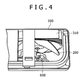
- Fig. 4 is a schematic sectional view showing a section of the air conditioner outdoor machine.
- An air conditioner outdoor machine 100 with the noise reducing structure in a fan device of Figs. 1 to 4 applied thereto includes a fan 200, noise reducing structures 310, 320, 330, a bell-mouth-like shroud 400, a front panel 500 and a drive motor 600.
- a shaft of the fan 200 is disposed along a horizontal axis and the bell-mouth-like shroud 400 is formed in the front panel 500 so that the outside air can be allowed to flow forward from the back with rotation of the fan 200.
- the noise reducing structures 310, 320 and 330 are disposed on the back side of the front panel 500 along the outer periphery surface of the bell-mouth-like shroud 400.
- the noise reducing structures 310, 320 and 330 are formed at a height almost equal to the length of the shroud 400 formed in the front panel 500.
- a large number of holes are formed so as to open in the direction opposite to the front panel 500.
- the noise reducing structures 310, 320 and 330 are not formed in the portion where they exert an influence on an air flow created by both fan 200 and bell-mouth-like shroud 400.
- the shaft of the fan 200 is connected to the drive motor 600 so that the fan 200 can be rotated by operation of the drive motor 600.
- Fig. 5 is a schematic sectional view showing an example of a line A-A section of the air conditioner outdoor machine 100 shown in Figs. 2 and 3 .
- the shroud 400 is disposed symmetrically with respect to an axis CL of the fan 200 of the air conditioner outdoor machine 100 and the noise reducing structures 310 and 330 are disposed on the back side of the front panel 500.
- a description will be given below about an example of the noise reducing structures 310, 320 and 330.
- Fig. 6 is a schematic sectional view showing a structural example of the noise reducing structures 310, 320 and 330.
- the noise reducing structures 310, 320 and 330 are formed by perforated plates 301, 302, a side plate 304 and a flat plate 305. Apart of them may be formed by the front panel 500. More particularly, the noise reducing structures 310, 320 and 330 may be formed by molding integrally with the front panel 500.
- the perforated plate 301 (surface layer) and the perforated plate 302 are spaced a distance L1 from each other and an air layer corresponding to the distance L1 is formed.
- the perforated plate 302 and the flat plate 305 are spaced a distance L2 from each other and an air layer corresponding to the distance L2 is formed.
- the holes of the perforated plates 301 and 302 be in at least one shape selected from among small hole, circular hole, deformed hole, slit-like hole, louver fin-like hole, crossed hole, and any other arbitrary shape.
- the holes are assumed to be circular holes.
- the perforated plate 301 has a thickness of 0.15 mm, a percentage holes of 0.3% and a hole diameter of 0.5 mm.
- the perforated plate 302 has a thickness of 0.29 mm, a percentage holes of 0.1% and a hole diameter of 0.5 mm.
- the perforated plates 301 and 302 be formed by an aluminum plate, a steel plate, or a plastic plate. It is optional whether the holes of the perforated plates 301 and 302 are formed by punching or by embossing.
- the distance L1 between the perforated plates 301 and 302 is 20 mm and the distance L2 between the perforated plate 302 and the flat plate 305 is 45 mm.
- Fig. 7 is a schematic sectional view showing another structural example of the noise reducing structures 310, 320 and 330 shown in Fig. 6 .
- the noise reducing structures 310, 320 and 330 are made up of perforated plates 301, 302, 303, side plate 304, flat plate 305 and partition plate 308. A part of them may be formed by the front panel 500. More particularly, the noise reducing structures 310, 320 and 330 may be formed by molding integrally with the front panel 500.
- the perforated plates 301 and 302 are spaced a distance L1 from each other and an air layer corresponding to the distance L1 is formed.
- the perforated plates 302 and 303 are spaced a distance L2 from each other and an air layer corresponding to the distance L2 is formed.
- the perforated plate 303 and the flat plate 305 are spaced a distance L3 from each other and an air layer corresponding to the distance L3 is formed.
- the partition plate 308 is disposed in each air layer.
- the distance L5 between adjacent partition plates 308 is set to a value of half or less of a main frequency of the noise generated in the air conditioner outdoor machine 100.
- the noise generated in the interior of the air conditioner outdoor machine 100 can be reduced by the noise reducing structures 310, 320 and 330.
- the noise reducing structures 310, 320 and 330 are not disposed in the portion of the shroud 400 facing the air flow, the air flow is not disturbed and it is possible to attain the reduction of noise without deteriorating the air feed capacity of the fan 200.
- the noise reducing structures 310, 320 and 330 are formed by molding integrally with the front panel 500, the number of assembling steps decreases, thus permitting the reduction of cost.
- the noise reducing structures 310, 320 and 330 are formed as independent members, the noise reducing structures 310, 320 and 330 can be disposed also in the portion where integral molding with the front panel 500 is difficult.
- the noise reducing structures 310, 320 and 330 are each constituted by one or plural perforated plates 301, 302 and 303, vibration of the air present within the air conditioner outdoor machine 100 is damped by viscous damping which is induced by vibration of air within the perforated plates 301, 302 and 303, thus permitting the reduction of noise.
- the environmental resistance of the sound absorbing structure according to the present invention can be kept high and the performance and structure of the sound absorbing structure do not undergo a change over a long period. Therefore, even in long-term use thereof, the noise reducing performance is not deteriorated.
- the perforated plates 301, 302 and 303 are formed in a direction perpendicular to the air flow direction (motor axis direction) and toward the interior of the front panel 500, it is possible to efficiently reduce the noise generated in the interior of the air conditioner outdoor machine 100.
- the plural perforated plates 301, 302 and 303 are different in the porosity in such a manner that the porosity becomes smaller in order from the outermost layer toward inner layers, more particularly, the perforated plate 301 is the largest and the perforated plate 303 is the smallest in the porosity. Consequently, the noise generated in the interior of the fan 200 can be reduced stepwise and effectively.
- partition plates 308 are formed in the noise reducing structures 310, 320 and 330 so that the spacing between the adjacent partition plates 308 is half or less of the wavelength of noise generated in the interior of the air conditioner outdoor machine 100, the noise generated in the interior of the air conditioner outdoor machine 100 can be prevented from increase in the air chambers formed behind the perforated plates 301, 302 and 303. As a result, the noise reducing structures 310, 320 and 330 can reduce noise effectively.
- Fig. 8 is a schematic sectional view showing another example of a line A-A section of the air conditioner outdoor machine 100 shown in Fig. 5 .
- the shroud 400 is disposed symmetrically with respect to the axis CL of the fan 200 of the air conditioner outdoor machine 100 and noise reducing structures 310a and 330a are disposed on the back side of the front panel 500.
- the noise reducing structures 310a and 330a shown in Fig. 8 are constituted by perforated plates 301a and 302a.
- the perforated plate 301a is disposed substantially in parallel with the fan axis CL, while the perforated plate 302a is disposed at an acute angle (0° to 90°) relative to the perforated plate 301a.
- the noise reducing structures 310a, 320a and 330a can reduce noise effectively.
- Fig. 9 is a schematic sectional view showing a further example of a line A-A section of the air conditioner outdoor machine 100 shown in Fig. 5 .
- the shroud 400 is disposed symmetrically with respect to the axis CL of the fan 200 of the air conditioner outdoor machine 100 and noise reducing structures 310b and 330b are disposed on the back side of the front panel 500.
- the noise reducing structures 310b and 330b shown in Fig. 9 are constituted by perforated plates 301b and 302b.
- the perforated plate 301b is disposed in a smoothly contiguous manner from an end of the shroud 400, while the perforated plate 302b is disposed in parallel with the front panel 500 and perpendicularly to the axis CL.
- the noise reducing structures 310b, 320b and 330b can reduce noise effectively.
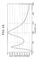
- Fig. 10 shows a simulation result of a sound absorption coefficient in Example 1.
- a sound absorption coefficient is plotted along the axis of ordinate and frequency is plotted along the axis of abscissa.
- the noise reducing structures 310, 320 and 330 shown in Fig. 6 were designed so as to permit reduction of noises at frequencies near 250 Hz and 1000 Hz. The effect thereof was checked by simulation. As a result, high sound absorption coefficients were observed at frequencies near 250 Hz and 1000 Hz as shown in Fig.10 . Moreover, since sound absorption coefficients obtained in the frequency range of 250 Hz to 1500 Hz are not smaller than 0.3, it is seen that the reduction of noise can be attained over a wide frequency band.
- the noise reducing structures 310, 320 and 330 described in Example 1 were applied to the air conditioner outdoor machine 100 shown in Fig. 1 .
- the air conditioner outdoor machine 100 was installed within a semi- anechoic room and the measurement of noise was conducted at a distance of 1 m from the front face of the outdoor machine.
- Fig. 11 shows sound pressure level in Example 2 and Comparative Example 1.
- the sound pressure level (dBA) is plotted along the axis of ordinate and 1/3 Oct.
- Band center frequency (Hz) is plotted along the axis of abscissa.
- a solid line A shows the result of Example 2 and a dotted line B shows the result of Comparative Example 1.
- Fig. 11 shows that in the 1/3 Oct. Band center frequency (Hz) range of 160 Hz to 250 Hz a sound pressure level of a solid line A in Example 2 is much lower than that of a dotted line B in Comparative Example 1. Further, it is seen that the sound pressure level drops also in the range from 1000 Hz to 1600 Hz. Thus, it turned out that the noise level (the sum of all frequency bands) could be reduced 1 dB in Example 2 as compared with Comparative Example 1.
- Hz 1/3 Oct. Band center frequency
- Fig. 12 shows an example of power consumption of the drive motor 600 in the air conditioner outdoor machine 100.
- power consumption (W) is plotted along the axis of ordinate and time (sec) is plotted along the axis of abscissa.
- a solid line A represents the state of Example 2 and a dotted line B represents the state of Comparative Example 1.
- the air feed capacity of the fan 200 was also presumed to have undergone no change. As a result, it turned out that the air feed capacity in the air conditioner outdoor machine 100 was not deteriorated.
- the fan 200 corresponds to the fan defined in the present invention
- the front panel 500 corresponds to a part of the housing
- the shroud 400 corresponds to the shroud formed by a bell-mouth-like inner surface
- the noise reducing structures 310, 320 and 330 corresponds to the sound absorbing structure
- the perforated plates 301, 302 and 303 correspond to one or plural perforated plates
- the partition plates 308 correspond to one or plural partition plates.
- a noise reducing structure in a fan device is provided which can reduce noise generated in the interior of a housing of the fan device without deteriorating the air feed capacity of the fan device.
- a fan (200) is rotated by a drive motor (600) to create an air flow.
- the air flow is introduced and uniformed by a bell-mouth-like shroud (400).
- Sound absorbing structures (310, 320, 330) are formed on a surface intersecting the outer periphery surface of the shroud (400).
Landscapes
- Engineering & Computer Science (AREA)
- Mechanical Engineering (AREA)
- General Engineering & Computer Science (AREA)
- Structures Of Non-Positive Displacement Pumps (AREA)
- Motor Or Generator Frames (AREA)
- Cooling Or The Like Of Electrical Apparatus (AREA)
Abstract
Description
- The present invention relates to a noise reducing structure in a fan device provided with a fan for creating an air flow, the noise reducing structure being capable of reducing noise generated in the interior of a housing of the fan device.
- In a conventional fan device there is provided a drive unit for creating an air flow and there is formed a bell- mouth-like shroud for improving the air feed capacity. In the fan device, noise attributable to the air flow and noise from the drive unit are generated in the interior of the housing. As examples of devices using the fan device there are known a cooling device for a vehicle engine, a cooling device for a computer, a ventilating device in a bathroom, and an outdoor machine of an air conditioner.
- In
Patent Literature 1 there is disclosed a compressor unit noise reducing device, the noise reducing device comprising compressor unit noise reducing means using a fan cover which functions to reduce noise generated in an outer fan portion of a compressor driving motor forming a compressor unit noise source and further functions to absorb and damp the associated vibration, and additional noise reducing means including intervention of a vibration damping material to a mounting surface and affixing of a vibration damping member to a vibrating member, thereby making a required noise reduction possible even in the absence of an enclosure. - In the compressor unit noise reducing device disclosed in
Patent Literature 1, the fan cover constitutes the noise reducing means of a non-explosionproof type motor of the compressor unit, is made up of an aperture cover, a sound absorbing material lined through soft rubber to an inner vibrating portion, and a woven wire mesh material and a vibration damping material both covering a front side of the aperture. - In
Patent Literature 2 there is disclosed a fan device noise reducing mechanism capable of damping an impact sound and an air flow sound effectively and thereby capable of reducing noise positively. - According to the fan device noise reducing mechanism disclosed in
Patent Literature 2, a porous sound absorbing material is affixed to the whole of the inner periphery surface of a fan shroud opposed to the front end side of the fan in an exposed state into the opposed space without using the conventional punching metal. Therefore, an air flow sound which is attributable to a strong rotating flow between the fan and the fan shroud can be absorbed by the sound absorbing material; besides, it is possible to make the generation of an impact sound difficult. Thus, both impact sound and air flow sound can be damped effectively and thus it is possible to attain the reduction of noise positively. - Further, in
Patent Literature 3 there is disclosed a bell- mouth of a blower having a pressure variation absorbing structure difficult for dust to adhere on an air flow guide surface and capable of maintaining a pressure variation absorbing effect even with the elapse of time. - The blower bell-mouth disclosed in
Patent Literature 3 is mounted in corresponding relation to an outer periphery of a blower impeller to guide air present on a suction side of the impeller to a blow-off side. The interior of the bell-mouth is formed as a hollow tubular structure, a large number of small holes are formed in an inner periphery wall portion which constitutes the air flow guide surface, and the interior hollow space is brought into communication with an outer air feed passage through those small holes. According to this construction, by forming the inner periphery wall portion with use of synthetic resin or metal, the air flow guide surface can be formed smooth to make the adherence of dust difficult; besides, dust which has entered the small holes is sucked into the interior space without staying within the small holes, thus making it possible to prevent the deposition of dust. -
- [Patent Literature 1]
Japanese Patent Laid-Open Publication No.2003-343495 - [Patent Literature 2]
Japanese Patent Laid-Open Publication No.2001-003750 - [Patent Literature 3]
Japanese Patent Laid-Open Publication No.2001-107899 - However, in the compressor unit noise reducing device disclosed in
Patent Literature 1, since a porous sound absorbing material is disposed in the intake aperture portion, the resistance to the air flow increases, resulting in decrease of the flow rate and deterioration of the air feed capacity of the fan device. - In the fan device noise reducing mechanism disclosed in
Patent Literature 2, since a porous sound absorbing material having concaves and convexes on the surface thereof is disposed at a position facing the air flow, the resistance to the air flow increases, with consequent decrease of the flow rate and deterioration of the air feed capacity of the fan device. Moreover, the sound absorbing effect attained by the porous sound absorbing material is generally limited to a high frequency region and the sound absorbing effect attained by holes, resonance pipes and a sound deadening room is limited to a narrow frequency band, thus making it impossible to obtain a noise reducing effect over a wide range of frequency band. Further, for protecting the porous sound absorbing material against water and dust it is necessary to apply a scientific water repelling treatment and surface coating to the material, thus resulting in increase of cost. - In the bell-mouth disclosed in
Patent Literature 3, since a large number of small holes are formed in the guide surface of the bell-mouth, the resistance to the air flow increases, so that the flow rate decreases and the air feed capacity of the fan device is very likely to be deteriorated. - It is an object of the present invention to provide a noise reducing structure in a fan device capable of reducing noise released from the interior of a housing of the fan device to the exterior without deteriorating the air feed capacity of the fan device.
-
- (1) According to the present invention there is provided a noise reducing structure in a fan device including a fan for creating an air flow, a housing for accommodating the fan therein, and a shroud provided in part of the housing, further includes a sound absorbing structure disposed in the interior of the housing and on an outer periphery side of the shroud.
- When the fan rotates and an air flow is created in the noise reducing structure in a fan device according to the present invention, the air flow is introduced and uniformed by the shroud. The sound absorbing structure is disposed on the outer periphery side of the shroud.
- In this case, noise generated in the interior of the fan device housing can be reduced by the sound absorbing structure. In this case, since the sound absorbing structure is not disposed at the shroud position facing the fan, the air flow is not disturbed and the noise released from the interior of the fan device housing to the exterior can be reduced without deteriorating the air feed capacity of the fan device.
- (2) The sound absorbing structure may be formed integrally with the housing.
- In this case, since the sound absorbing structure is integral with the housing, the number of assembling steps becomes smaller and hence it is possible to reduce the manufacturing cost.
- (3) The sound absorbing structure may be formed as an independent member.
- In this case, since the sound absorbing structure is formed as an independent member, the sound absorbing structure can be provided even at a position where integral molding with the housing is difficult.
- (4) The sound absorbing structure may be formed by one perforated plate and an air layer, or plural perforated plates arranged in a layered fashion and plural air layers.
- In this case, since the sound absorbing structure is constituted by one perforated plate or a plurality of layered, perforated plates, vibration of the air present within the housing is damped by viscous damping which is induced by vibration of air within each of the holes of the perforated plate, thus making is possible to reduce noise. Besides, since the sound absorbing structure is constituted by a plate member, the environmental resistance of the sound absorbing structure according to the present invention can be maintained high and the performance and structure of the sound absorbing structure do not change over a long period. Therefore, even if the sound absorbing material is used for a long period, its noise reducing performance is not deteriorated. Moreover, since there is no scattering of the sound absorbing structure in comparison with the conventional sound absorbing materials, it is possible to prevent a bad influence on the ambient environment or devices. In case of forming concaves and convexes on the perforated plate(s) by embossing, the rigidity of the perforated plate(s) is improved and hence it is possible to prevent the generation of a solid sound.
- (5) The perforated plate(s) may be disposed so as to face toward the interior of the housing.
- In this case, since the perforated plate(s) is (are) disposed so as to face toward the interior of the housing, the sound absorbing structure can efficiently reduce the noise generated in the interior of the housing. Besides, since the sound absorbing structure is not disposed at the position where the shroud faces the fan, the air flow is no disturbed and the noise released from the interior of the fan device housing to the exterior can be reduced without deteriorating the air feed capacity of the fan device.
- (6) The shroud may be constituted by a cylindrical wall, the cylindrical wall being formed so as to be spaced a predetermined distance from a fan shaft which is formed perpendicularly to a front panel as a constituent of the housing, and the perforated plate(s) may be disposed substantially perpendicularly to the fan shaft.
- In this case, the sound absorbing structure is attached to the front panel which constitutes a part of the housing. The position where the sound absorbing structure is mounted is on the outer periphery side of the shroud and in an empty area of the housing. The sound absorbing structure is disposed so that its perforated surface is perpendicular to the fan shaft. That is, the perforated surface faces toward the interior of the housing. Consequently, the noise generated in the interior of the housing can be reduced efficiently. Moreover, since no sound absorbing structure is formed on the inner periphery surface of the shroud, the air flow is not obstructed and it is possible to prevent deterioration of the air feeding capacity of the fan device.
(7) The plural perforated plates may be different in the porosity in such a manner that the porosity becomes smaller in order from the outermost surface layer toward an inner layer(s). - In this case, since the plural perforated plates are different in the porosity in such a manner the porosity becomes smaller in order from the outermost layer toward an inner layer(s), the noise generated in the interior of the fan device can be reduced stepwise and effectively.
- (8) One or more partition plates are disposed in the one or plural air layers so as to divide the one or plural air layers in-plane direction of the perforated plate(s) at a spacing of half or less of the wavelength of noise concerned which is generated in the interior of the housing.
- In this case, since partition plates are formed so as to divide the one or plural air layers at a spacing of half or less of the wavelength of noise concerned which is generated in the interior of the housing, there occurs resonance in an air chamber formed behind each perforated plate, whereby it is possible to prevent an increase of the noise in the interior of the housing. As a result, the sound absorbing structure can reduce noise effectively.
-
-
Fig. 1 is a schematic diagram showing the appearance of an air conditioner outdoor machine to which is applied a noise reducing structure in a fan device according to an embodiment of the present invention; -
Fig. 2 is a schematic plan view showing a back side of a front panel of the air conditioner outdoor machine ofFig. 1 ; -
Fig. 3 is a schematic perspective view showing the back side of the front panel of the air conditioner outdoor machine ofFig. 2 ; -
Fig. 4 is a schematic sectional view showing a section of the air conditioner outdoor machine; -
Fig. 5 is a schematic sectional view showing an example of a line A-A section of the air conditioner outdoor machine; -
Fig. 6 is a schematic sectional view showing a structural example of the noise reducing structure; -
Fig. 7 is a schematic sectional view showing another structural example of the noise reducing structure shown inFig. 6 ; -
Fig. 8 is a schematic sectional view showing another example of a line A-A section of the air conditioner outdoor machine; -
Fig. 9 is a schematic sectional view showing a further example of a line A-A section of the air conditioner outdoor machine; -
Fig. 10 shows a simulation result of a sound absorption coefficient in Example 1; -
Fig. 11 shows changes in sound pressure level in Example 2 and Comparative Example 1; and -
Fig. 12 shows an example of power consumption of a drive motor used in the air conditioner outdoor machine. - An embodiment of the present invention will be described hereinunder. In this embodiment the noise reducing structure in a fan device of the present invention is applied to an air conditioner outdoor machine. However, no limitation is made to the air conditioner outdoor machine. The present invention is applicable also to a vehicular engine cooling device, a computer cooling device, a bathroom ventilating device and any other fan device.
-
Fig. 1 is a schematic diagram showing the appearance of an air conditioner outdoor machine to which is applied the noise reducing structure in a fan device according to the present invention,Fig. 2 is a schematic plan view showing a back side of a front panel of the air conditioner outdoor machine ofFig.1 ,Fig. 3 is a schematic perspective view showing the back side of the front panel of the air conditioner outdoor machine ofFig.2 , andFig. 4 is a schematic sectional view showing a section of the air conditioner outdoor machine. - An air conditioner
outdoor machine 100 with the noise reducing structure in a fan device ofFigs. 1 to 4 applied thereto includes afan 200,noise reducing structures like shroud 400, afront panel 500 and adrive motor 600. - As shown in
Fig. 1 , in the air conditioneroutdoor machine 100, which is in the shape of a rectangular parallelepiped, a shaft of thefan 200 is disposed along a horizontal axis and the bell-mouth-like shroud 400 is formed in thefront panel 500 so that the outside air can be allowed to flow forward from the back with rotation of thefan 200. - As shown in
Figs. 2 and3 , thenoise reducing structures front panel 500 along the outer periphery surface of the bell-mouth-like shroud 400. Thenoise reducing structures shroud 400 formed in thefront panel 500. In each of thenoise reducing structures front panel 500. - In this case, in the internal structure of the air conditioner
outdoor machine 100, as shown inFig. 4 , thenoise reducing structures fan 200 and bell-mouth-like shroud 400. The shaft of thefan 200 is connected to thedrive motor 600 so that thefan 200 can be rotated by operation of thedrive motor 600. -
Fig. 5 is a schematic sectional view showing an example of a line A-A section of the air conditioneroutdoor machine 100 shown inFigs. 2 and3 . - As shown in
Fig. 5 , theshroud 400 is disposed symmetrically with respect to an axis CL of thefan 200 of the air conditioneroutdoor machine 100 and thenoise reducing structures front panel 500. A description will be given below about an example of thenoise reducing structures -
Fig. 6 is a schematic sectional view showing a structural example of thenoise reducing structures - As shown in
Fig. 6 , thenoise reducing structures perforated plates side plate 304 and aflat plate 305. Apart of them may be formed by thefront panel 500. More particularly, thenoise reducing structures front panel 500. The perforated plate 301 (surface layer) and theperforated plate 302 are spaced a distance L1 from each other and an air layer corresponding to the distance L1 is formed. Likewise, theperforated plate 302 and theflat plate 305 are spaced a distance L2 from each other and an air layer corresponding to the distance L2 is formed. - In the
perforated plates perforated plates - In this embodiment the holes are assumed to be circular holes. In this embodiment the
perforated plate 301 has a thickness of 0.15 mm, a percentage holes of 0.3% and a hole diameter of 0.5 mm. - In this embodiment the
perforated plate 302 has a thickness of 0.29 mm, a percentage holes of 0.1% and a hole diameter of 0.5 mm. - From the standpoint of recycling and strength it is preferable that the
perforated plates perforated plates - In this embodiment the distance L1 between the
perforated plates perforated plate 302 and theflat plate 305 is 45 mm. -
Fig. 7 is a schematic sectional view showing another structural example of thenoise reducing structures Fig. 6 . - As shown in
Fig. 7 , thenoise reducing structures perforated plates side plate 304,flat plate 305 andpartition plate 308. A part of them may be formed by thefront panel 500. More particularly, thenoise reducing structures front panel 500. Theperforated plates perforated plates perforated plate 303 and theflat plate 305 are spaced a distance L3 from each other and an air layer corresponding to the distance L3 is formed. Thepartition plate 308 is disposed in each air layer. The distance L5 betweenadjacent partition plates 308 is set to a value of half or less of a main frequency of the noise generated in the air conditioneroutdoor machine 100. As a result, there occurs resonance in air chambers formed behind theperforated plates - Thus, the noise generated in the interior of the air conditioner
outdoor machine 100 can be reduced by thenoise reducing structures noise reducing structures shroud 400 facing the air flow, the air flow is not disturbed and it is possible to attain the reduction of noise without deteriorating the air feed capacity of thefan 200. Moreover, in the case where thenoise reducing structures front panel 500, the number of assembling steps decreases, thus permitting the reduction of cost. In the case where thenoise reducing structures noise reducing structures front panel 500 is difficult. - Moreover, since the
noise reducing structures perforated plates outdoor machine 100 is damped by viscous damping which is induced by vibration of air within theperforated plates - In this case, in the
noise reducing structures perforated plates front panel 500, it is possible to efficiently reduce the noise generated in the interior of the air conditioneroutdoor machine 100. - The plural
perforated plates perforated plate 301 is the largest and theperforated plate 303 is the smallest in the porosity. Consequently, the noise generated in the interior of thefan 200 can be reduced stepwise and effectively. - In this case, since
partition plates 308 are formed in thenoise reducing structures adjacent partition plates 308 is half or less of the wavelength of noise generated in the interior of the air conditioneroutdoor machine 100, the noise generated in the interior of the air conditioneroutdoor machine 100 can be prevented from increase in the air chambers formed behind theperforated plates noise reducing structures -
Fig. 8 is a schematic sectional view showing another example of a line A-A section of the air conditioneroutdoor machine 100 shown inFig. 5 . - As shown in
Fig. 8 , theshroud 400 is disposed symmetrically with respect to the axis CL of thefan 200 of the air conditioneroutdoor machine 100 andnoise reducing structures front panel 500. Thenoise reducing structures Fig. 8 are constituted byperforated plates perforated plate 301a is disposed substantially in parallel with the fan axis CL, while theperforated plate 302a is disposed at an acute angle (0° to 90°) relative to theperforated plate 301a. - With this arrangement, the
noise reducing structures -
Fig. 9 is a schematic sectional view showing a further example of a line A-A section of the air conditioneroutdoor machine 100 shown inFig. 5 . - As shown in
Fig. 9 , theshroud 400 is disposed symmetrically with respect to the axis CL of thefan 200 of the air conditioneroutdoor machine 100 andnoise reducing structures front panel 500. Thenoise reducing structures Fig. 9 are constituted byperforated plates perforated plate 301b is disposed in a smoothly contiguous manner from an end of theshroud 400, while theperforated plate 302b is disposed in parallel with thefront panel 500 and perpendicularly to the axis CL. - With this arrangement, the
noise reducing structures - In this Example there was performed simulation of a sound absorption coefficient with respect to a structural example of the
noise reducing structures Fig. 6 . -
Fig. 10 shows a simulation result of a sound absorption coefficient in Example 1. In the same figure, a sound absorption coefficient is plotted along the axis of ordinate and frequency is plotted along the axis of abscissa. - The
noise reducing structures Fig. 6 were designed so as to permit reduction of noises at frequencies near 250 Hz and 1000 Hz. The effect thereof was checked by simulation. As a result, high sound absorption coefficients were observed at frequencies near 250 Hz and 1000 Hz as shown inFig.10 . Moreover, since sound absorption coefficients obtained in the frequency range of 250 Hz to 1500 Hz are not smaller than 0.3, it is seen that the reduction of noise can be attained over a wide frequency band. - The
noise reducing structures outdoor machine 100 shown inFig. 1 . In accordance with JIS C9612 the air conditioneroutdoor machine 100 was installed within a semi- anechoic room and the measurement of noise was conducted at a distance of 1 m from the front face of the outdoor machine. - In this Comparative Example the measurement of noise was conducted for the air conditioner
outdoor machine 100 not using thenoise reducing structures -
Fig. 11 shows sound pressure level in Example 2 and Comparative Example 1. The sound pressure level (dBA) is plotted along the axis of ordinate and 1/3 Oct. Band center frequency (Hz) is plotted along the axis of abscissa. InFig.11 , a solid line A shows the result of Example 2 and a dotted line B shows the result of Comparative Example 1. -
Fig. 11 shows that in the 1/3 Oct. Band center frequency (Hz) range of 160 Hz to 250 Hz a sound pressure level of a solid line A in Example 2 is much lower than that of a dotted line B in Comparative Example 1. Further, it is seen that the sound pressure level drops also in the range from 1000 Hz to 1600 Hz. Thus, it turned out that the noise level (the sum of all frequency bands) could be reduced 1 dB in Example 2 as compared with Comparative Example 1. - Next, in order to check whether the air feed capacity of the fan device was influenced or not, power consumption of the
drive motor 600 in the air conditioneroutdoor machine 100 was measured. -
Fig. 12 shows an example of power consumption of thedrive motor 600 in the air conditioneroutdoor machine 100. InFig. 12 , power consumption (W) is plotted along the axis of ordinate and time (sec) is plotted along the axis of abscissa. In the same figure, a solid line A represents the state of Example 2 and a dotted line B represents the state of Comparative Example 1. - As shown in
Fig. 12 , there occurred no significant difference between the state of Example 2 indicated by the solid line A and that of Comparative Example 1 indicated by the dotted line B. - Thus, because of no difference in power consumption of the
drive motor 600, the air feed capacity of thefan 200 was also presumed to have undergone no change. As a result, it turned out that the air feed capacity in the air conditioneroutdoor machine 100 was not deteriorated. - In the above embodiment of the present invention, the
fan 200 corresponds to the fan defined in the present invention, and likewise thefront panel 500 corresponds to a part of the housing, theshroud 400 corresponds to the shroud formed by a bell-mouth-like inner surface, thenoise reducing structures perforated plates partition plates 308 correspond to one or plural partition plates. - The present invention is as described in the above preferred embodiment, but no limitation is made thereto. It will be understood that various other embodiments may be made within the scope not departing from the spirit and scope of the present invention. Further, although in the above embodiment reference has been made to the function and effect attained by the construction of the present invention, such function and effect are a mere example and do not limit the present invention.
A noise reducing structure in a fan device is provided which can reduce noise generated in the interior of a housing of the fan device without deteriorating the air feed capacity of the fan device. In the noise reducing structure in a fan device, a fan (200) is rotated by a drive motor (600) to create an air flow. The air flow is introduced and uniformed by a bell-mouth-like shroud (400). Sound absorbing structures (310, 320, 330) are formed on a surface intersecting the outer periphery surface of the shroud (400).
Claims (8)
- A noise reducing structure in a fan device including:a fan for creating an air flow;a housing for accommodating said fan therein; anda shroud provided in part of said housing,said noise reducing structure, comprising:a sound absorbing structure disposed in the interior of said housing and on an outer periphery side of said shroud.
- A noise reducing structure in a fan device according to claim 1, wherein said sound absorbing structure is formed integrally with said housing.
- A noise reducing structure in a fan device according to claim 1, wherein said sound absorbing structure is formed as an independent member.
- A noise reducing structure in a fan device according to any of claims 1 to 3, wherein said sound absorbing structure is formed by one perforated plate and an air layer, or a plurality of perforated plates arranged in a layered fashion and a plurality of air layers.
- A noise reducing structure in a fan device according to claim 4, wherein said perforated plate(s) is (are) disposed toward the interior of said housing.
- A noise reducing structure in a fan device according to claim 4 or claim 5, wherein said shroud is constituted by a cylindrical wall, said cylindrical wall being formed so as to be spaced a predetermined distance from a fan shaft which is formed perpendicularly to a front panel as a constituent of said housing, and said perforated plate(s) is (are) disposed substantially perpendicularly to said fan shaft.
- A noise reducing structure in a fan device according to any of claims 4 to 6, wherein said plural perforated plates are different in the porosity in such a manner that the porosity becomes smaller in order from the outermost surface layer toward an inner layer(s).
- A noise reducing structure in a fan device according to any of claims 4 to 7, wherein one or more partition plates are disposed in said one or plural air layers so as to divide the one or plural air layers in-plane direction of said perforated plate(s) at a spacing of half or less of the wavelength of noise concerned which is generated in the interior of said housing.
Applications Claiming Priority (1)
| Application Number | Priority Date | Filing Date | Title |
|---|---|---|---|
| JP2007102082A JP2008255969A (en) | 2007-04-09 | 2007-04-09 | Noise reducing structure of fan device |
Publications (2)
| Publication Number | Publication Date |
|---|---|
| EP1980755A2 true EP1980755A2 (en) | 2008-10-15 |
| EP1980755A3 EP1980755A3 (en) | 2012-05-16 |
Family
ID=39380914
Family Applications (1)
| Application Number | Title | Priority Date | Filing Date |
|---|---|---|---|
| EP08152389A Withdrawn EP1980755A3 (en) | 2007-04-09 | 2008-03-06 | Noise reducing structure in fan device |
Country Status (3)
| Country | Link |
|---|---|
| EP (1) | EP1980755A3 (en) |
| JP (1) | JP2008255969A (en) |
| CN (1) | CN101285488B (en) |
Cited By (10)
| Publication number | Priority date | Publication date | Assignee | Title |
|---|---|---|---|---|
| CN103089704A (en) * | 2011-10-31 | 2013-05-08 | Ge医疗系统环球技术有限公司 | Fan assembly and electric device with same |
| US8770340B2 (en) | 2011-11-16 | 2014-07-08 | Huntair, Inc. | Sound-absorptive panel for an air handling system |
| EP2899406A1 (en) * | 2014-01-22 | 2015-07-29 | Robert Bosch Gmbh | Cooling module with sound insulated blower |
| WO2015195108A1 (en) * | 2014-06-18 | 2015-12-23 | Hewlett-Packard Development Company, L. P. | Fan including an acoustic absorption member in contact and movable with vanes |
| CN108035791A (en) * | 2017-11-27 | 2018-05-15 | 三汽车制造有限公司 | A kind of wind scooper, engine and power-equipment |
| CN108240647A (en) * | 2017-10-31 | 2018-07-03 | 宁波方太厨具有限公司 | A kind of frequency conversion noise reduction outlet housing of range hood |
| CN108488103A (en) * | 2018-06-26 | 2018-09-04 | 杭州老板电器股份有限公司 | Noise reduction device, fan and range hood |
| US10323655B2 (en) | 2016-02-08 | 2019-06-18 | Nidec Corporation | Fan motor |
| CN110274276A (en) * | 2018-03-13 | 2019-09-24 | 宁波方太厨具有限公司 | A kind of noise reducing type range hood |
| EP3907407A1 (en) * | 2020-05-06 | 2021-11-10 | Carrier Corporation | Fan coil unit with silencer |
Families Citing this family (7)
| Publication number | Priority date | Publication date | Assignee | Title |
|---|---|---|---|---|
| JP5558449B2 (en) * | 2011-10-03 | 2014-07-23 | 三菱電機株式会社 | Blower, outdoor unit and refrigeration cycle apparatus |
| JP6240436B2 (en) | 2013-08-29 | 2017-11-29 | 株式会社スギヨ | Manufacturing method of sardine-like fish paste products |
| CN105570193B (en) * | 2014-11-24 | 2017-05-10 | 徐工集团工程机械股份有限公司 | Radiator wind scooper structure for engineering machine |
| CN106123153B (en) * | 2016-08-17 | 2022-04-12 | 广东美的制冷设备有限公司 | Air condensing units and air conditioner |
| CN114704495B (en) * | 2022-04-27 | 2026-04-17 | 奇鋐科技股份有限公司 | Fan frame noise reduction structure |
| US12597408B2 (en) | 2022-09-23 | 2026-04-07 | Toyota Motor Engineering & Manufacturing North America, Inc. | Sound absorbing devices for panels with openings |
| WO2026014087A1 (en) * | 2024-07-10 | 2026-01-15 | 富士フイルム株式会社 | Blower |
Citations (3)
| Publication number | Priority date | Publication date | Assignee | Title |
|---|---|---|---|---|
| JP2001003750A (en) | 1999-04-19 | 2001-01-09 | Komatsu Ltd | Noise reduction mechanism of fan unit |
| JP2001107899A (en) | 1999-10-12 | 2001-04-17 | Daikin Ind Ltd | Bell mouth structure of blower |
| JP2003343495A (en) | 2002-05-27 | 2003-12-03 | Mayekawa Mfg Co Ltd | Noise reduction device for compressor unit |
Family Cites Families (8)
| Publication number | Priority date | Publication date | Assignee | Title |
|---|---|---|---|---|
| JPS5769998A (en) * | 1980-10-20 | 1982-04-30 | Matsushita Electric Ind Co Ltd | Electromagnetic type pickup cartridge |
| JPS62142896A (en) * | 1985-12-18 | 1987-06-26 | Matsushita Seiko Co Ltd | Centrifugal blower |
| JPH03229998A (en) * | 1990-02-05 | 1991-10-11 | Matsushita Electric Ind Co Ltd | mixed flow blower |
| GB2330624A (en) * | 1997-10-23 | 1999-04-28 | Wang Samw Hong Jen | Fan device with noise reduction |
| JP2001153096A (en) * | 1999-11-30 | 2001-06-05 | Maruyama Mfg Co Ltd | Centrifugal blower and portable blower |
| JP2003050586A (en) * | 2000-09-29 | 2003-02-21 | Kobe Steel Ltd | Porous soundproof structure and method of manufacturing the same |
| JP4223438B2 (en) * | 2003-05-30 | 2009-02-12 | 株式会社神戸製鋼所 | Porous soundproof structure |
| US7080514B2 (en) * | 2003-08-15 | 2006-07-25 | Siemens Power Generation,Inc. | High frequency dynamics resonator assembly |
-
2007
- 2007-04-09 JP JP2007102082A patent/JP2008255969A/en active Pending
-
2008
- 2008-02-01 CN CN2008100086399A patent/CN101285488B/en not_active Expired - Fee Related
- 2008-03-06 EP EP08152389A patent/EP1980755A3/en not_active Withdrawn
Patent Citations (3)
| Publication number | Priority date | Publication date | Assignee | Title |
|---|---|---|---|---|
| JP2001003750A (en) | 1999-04-19 | 2001-01-09 | Komatsu Ltd | Noise reduction mechanism of fan unit |
| JP2001107899A (en) | 1999-10-12 | 2001-04-17 | Daikin Ind Ltd | Bell mouth structure of blower |
| JP2003343495A (en) | 2002-05-27 | 2003-12-03 | Mayekawa Mfg Co Ltd | Noise reduction device for compressor unit |
Cited By (13)
| Publication number | Priority date | Publication date | Assignee | Title |
|---|---|---|---|---|
| CN103089704A (en) * | 2011-10-31 | 2013-05-08 | Ge医疗系统环球技术有限公司 | Fan assembly and electric device with same |
| CN103089704B (en) * | 2011-10-31 | 2017-03-01 | Ge医疗系统环球技术有限公司 | Fan component and the electrical equipment with this fan component |
| US8770340B2 (en) | 2011-11-16 | 2014-07-08 | Huntair, Inc. | Sound-absorptive panel for an air handling system |
| EP2899406A1 (en) * | 2014-01-22 | 2015-07-29 | Robert Bosch Gmbh | Cooling module with sound insulated blower |
| WO2015195108A1 (en) * | 2014-06-18 | 2015-12-23 | Hewlett-Packard Development Company, L. P. | Fan including an acoustic absorption member in contact and movable with vanes |
| US10323655B2 (en) | 2016-02-08 | 2019-06-18 | Nidec Corporation | Fan motor |
| CN108240647A (en) * | 2017-10-31 | 2018-07-03 | 宁波方太厨具有限公司 | A kind of frequency conversion noise reduction outlet housing of range hood |
| CN108240647B (en) * | 2017-10-31 | 2023-11-17 | 宁波方太厨具有限公司 | Variable-frequency noise-reduction air outlet cover of range hood |
| CN108035791A (en) * | 2017-11-27 | 2018-05-15 | 三汽车制造有限公司 | A kind of wind scooper, engine and power-equipment |
| CN110274276A (en) * | 2018-03-13 | 2019-09-24 | 宁波方太厨具有限公司 | A kind of noise reducing type range hood |
| CN110274276B (en) * | 2018-03-13 | 2024-02-20 | 宁波方太厨具有限公司 | Noise-reducing type range hood |
| CN108488103A (en) * | 2018-06-26 | 2018-09-04 | 杭州老板电器股份有限公司 | Noise reduction device, fan and range hood |
| EP3907407A1 (en) * | 2020-05-06 | 2021-11-10 | Carrier Corporation | Fan coil unit with silencer |
Also Published As
| Publication number | Publication date |
|---|---|
| JP2008255969A (en) | 2008-10-23 |
| CN101285488B (en) | 2012-05-30 |
| CN101285488A (en) | 2008-10-15 |
| EP1980755A3 (en) | 2012-05-16 |
Similar Documents
| Publication | Publication Date | Title |
|---|---|---|
| JP2008255969A (en) | Noise reducing structure of fan device | |
| US7712576B2 (en) | Sound absorbing structure of electronic equipment | |
| JP7804608B2 (en) | Fan silencer system | |
| KR100998128B1 (en) | Low noise package of the machine | |
| JPH05106893A (en) | Ventilating fan | |
| JP7583117B2 (en) | Blower with silencer | |
| US4068736A (en) | Method and device for reducing noise | |
| JP2016170194A (en) | Sound absorber, and sound absorbing structure | |
| CN208765234U (en) | Assembling bracket, fan assembly and air conditioner | |
| US12257958B2 (en) | Silencing member for electrified vehicle | |
| JP5029593B2 (en) | Blower device | |
| JP2006292231A (en) | machine room | |
| CN110211560B (en) | Resonance sound absorption structure and air conditioner fan subassembly | |
| CN208671181U (en) | Assembling bracket, fan assembly and air conditioner | |
| EP4102071A1 (en) | A fluid flow regulation assembly with vibration attenuation | |
| US12529487B2 (en) | Ventilation path with soundproof structure | |
| KR101979378B1 (en) | Splitter and sound attenuator including the same | |
| JP2003041528A (en) | Sound absorbing structure | |
| WO2022013280A1 (en) | Sound-reducing panel for an axial fan apparatus | |
| JP2013181714A (en) | Muffling device | |
| JP2011112324A (en) | Outdoor unit of air conditioner | |
| JP2012018997A (en) | Sound absorbing structure of electronic device | |
| WO2026014357A1 (en) | Soundproof structure | |
| JP2014119148A (en) | Air conditioner outdoor unit | |
| WO2026014087A1 (en) | Blower |
Legal Events
| Date | Code | Title | Description |
|---|---|---|---|
| PUAI | Public reference made under article 153(3) epc to a published international application that has entered the european phase |
Free format text: ORIGINAL CODE: 0009012 |
|
| 17P | Request for examination filed |
Effective date: 20080306 |
|
| AK | Designated contracting states |
Kind code of ref document: A2 Designated state(s): AT BE BG CH CY CZ DE DK EE ES FI FR GB GR HR HU IE IS IT LI LT LU LV MC MT NL NO PL PT RO SE SI SK TR |
|
| AX | Request for extension of the european patent |
Extension state: AL BA MK RS |
|
| PUAL | Search report despatched |
Free format text: ORIGINAL CODE: 0009013 |
|
| AK | Designated contracting states |
Kind code of ref document: A3 Designated state(s): AT BE BG CH CY CZ DE DK EE ES FI FR GB GR HR HU IE IS IT LI LT LU LV MC MT NL NO PL PT RO SE SI SK TR |
|
| AX | Request for extension of the european patent |
Extension state: AL BA MK RS |
|
| RIC1 | Information provided on ipc code assigned before grant |
Ipc: F04D 29/66 20060101AFI20120412BHEP |
|
| RIN1 | Information on inventor provided before grant (corrected) |
Inventor name: TANAKA, TOSHIMITSU Inventor name: YAMAGIWA, ICHIRO Inventor name: TSUGIHASHI, KAZUKI |
|
| AKX | Designation fees paid |
Designated state(s): BE CZ |
|
| REG | Reference to a national code |
Ref country code: DE Ref legal event code: R108 |
|
| REG | Reference to a national code |
Ref country code: DE Ref legal event code: R108 Effective date: 20130123 |
|
| STAA | Information on the status of an ep patent application or granted ep patent |
Free format text: STATUS: THE APPLICATION IS DEEMED TO BE WITHDRAWN |
|
| 18D | Application deemed to be withdrawn |
Effective date: 20121117 |