EP1980672A1 - Pin connection device - Google Patents
Pin connection device Download PDFInfo
- Publication number
- EP1980672A1 EP1980672A1 EP06834330A EP06834330A EP1980672A1 EP 1980672 A1 EP1980672 A1 EP 1980672A1 EP 06834330 A EP06834330 A EP 06834330A EP 06834330 A EP06834330 A EP 06834330A EP 1980672 A1 EP1980672 A1 EP 1980672A1
- Authority
- EP
- European Patent Office
- Prior art keywords
- pin
- connection
- guide members
- pin guide
- portions
- Prior art date
- Legal status (The legal status is an assumption and is not a legal conclusion. Google has not performed a legal analysis and makes no representation as to the accuracy of the status listed.)
- Granted
Links
Images






Classifications
-
- E—FIXED CONSTRUCTIONS
- E02—HYDRAULIC ENGINEERING; FOUNDATIONS; SOIL SHIFTING
- E02F—DREDGING; SOIL-SHIFTING
- E02F3/00—Dredgers; Soil-shifting machines
- E02F3/04—Dredgers; Soil-shifting machines mechanically-driven
- E02F3/28—Dredgers; Soil-shifting machines mechanically-driven with digging tools mounted on a dipper- or bucket-arm, i.e. there is either one arm or a pair of arms, e.g. dippers, buckets
- E02F3/30—Dredgers; Soil-shifting machines mechanically-driven with digging tools mounted on a dipper- or bucket-arm, i.e. there is either one arm or a pair of arms, e.g. dippers, buckets with a dipper-arm pivoted on a cantilever beam, i.e. boom
- E02F3/301—Dredgers; Soil-shifting machines mechanically-driven with digging tools mounted on a dipper- or bucket-arm, i.e. there is either one arm or a pair of arms, e.g. dippers, buckets with a dipper-arm pivoted on a cantilever beam, i.e. boom with more than two arms (boom included), e.g. two-part boom with additional dipper-arm
-
- E—FIXED CONSTRUCTIONS
- E02—HYDRAULIC ENGINEERING; FOUNDATIONS; SOIL SHIFTING
- E02F—DREDGING; SOIL-SHIFTING
- E02F3/00—Dredgers; Soil-shifting machines
- E02F3/04—Dredgers; Soil-shifting machines mechanically-driven
- E02F3/28—Dredgers; Soil-shifting machines mechanically-driven with digging tools mounted on a dipper- or bucket-arm, i.e. there is either one arm or a pair of arms, e.g. dippers, buckets
- E02F3/30—Dredgers; Soil-shifting machines mechanically-driven with digging tools mounted on a dipper- or bucket-arm, i.e. there is either one arm or a pair of arms, e.g. dippers, buckets with a dipper-arm pivoted on a cantilever beam, i.e. boom
- E02F3/302—Dredgers; Soil-shifting machines mechanically-driven with digging tools mounted on a dipper- or bucket-arm, i.e. there is either one arm or a pair of arms, e.g. dippers, buckets with a dipper-arm pivoted on a cantilever beam, i.e. boom with an additional link
-
- E—FIXED CONSTRUCTIONS
- E02—HYDRAULIC ENGINEERING; FOUNDATIONS; SOIL SHIFTING
- E02F—DREDGING; SOIL-SHIFTING
- E02F3/00—Dredgers; Soil-shifting machines
- E02F3/04—Dredgers; Soil-shifting machines mechanically-driven
- E02F3/28—Dredgers; Soil-shifting machines mechanically-driven with digging tools mounted on a dipper- or bucket-arm, i.e. there is either one arm or a pair of arms, e.g. dippers, buckets
- E02F3/36—Component parts
- E02F3/369—Devices to connect parts of a boom or an arm
-
- E—FIXED CONSTRUCTIONS
- E02—HYDRAULIC ENGINEERING; FOUNDATIONS; SOIL SHIFTING
- E02F—DREDGING; SOIL-SHIFTING
- E02F3/00—Dredgers; Soil-shifting machines
- E02F3/04—Dredgers; Soil-shifting machines mechanically-driven
- E02F3/28—Dredgers; Soil-shifting machines mechanically-driven with digging tools mounted on a dipper- or bucket-arm, i.e. there is either one arm or a pair of arms, e.g. dippers, buckets
- E02F3/36—Component parts
- E02F3/38—Cantilever beams, i.e. booms;, e.g. manufacturing processes, forms, geometry or materials used for booms; Dipper-arms, e.g. manufacturing processes, forms, geometry or materials used for dipper-arms; Bucket-arms
- E02F3/382—Connections to the frame; Supports for booms or arms
-
- E—FIXED CONSTRUCTIONS
- E02—HYDRAULIC ENGINEERING; FOUNDATIONS; SOIL SHIFTING
- E02F—DREDGING; SOIL-SHIFTING
- E02F9/00—Component parts of dredgers or soil-shifting machines, not restricted to one of the kinds covered by groups E02F3/00 - E02F7/00
- E02F9/006—Pivot joint assemblies
-
- E—FIXED CONSTRUCTIONS
- E04—BUILDING
- E04G—SCAFFOLDING; FORMS; SHUTTERING; BUILDING IMPLEMENTS OR AIDS, OR THEIR USE; HANDLING BUILDING MATERIALS ON THE SITE; REPAIRING, BREAKING-UP OR OTHER WORK ON EXISTING BUILDINGS
- E04G23/00—Working measures on existing buildings
- E04G23/08—Wrecking of buildings
- E04G23/082—Wrecking of buildings using shears, breakers, jaws and the like
-
- F—MECHANICAL ENGINEERING; LIGHTING; HEATING; WEAPONS; BLASTING
- F16—ENGINEERING ELEMENTS AND UNITS; GENERAL MEASURES FOR PRODUCING AND MAINTAINING EFFECTIVE FUNCTIONING OF MACHINES OR INSTALLATIONS; THERMAL INSULATION IN GENERAL
- F16C—SHAFTS; FLEXIBLE SHAFTS; ELEMENTS OR CRANKSHAFT MECHANISMS; ROTARY BODIES OTHER THAN GEARING ELEMENTS; BEARINGS
- F16C11/00—Pivots; Pivotal connections
- F16C11/04—Pivotal connections
- F16C11/045—Pivotal connections with at least a pair of arms pivoting relatively to at least one other arm, all arms being mounted on one pin
-
- F—MECHANICAL ENGINEERING; LIGHTING; HEATING; WEAPONS; BLASTING
- F16—ENGINEERING ELEMENTS AND UNITS; GENERAL MEASURES FOR PRODUCING AND MAINTAINING EFFECTIVE FUNCTIONING OF MACHINES OR INSTALLATIONS; THERMAL INSULATION IN GENERAL
- F16C—SHAFTS; FLEXIBLE SHAFTS; ELEMENTS OR CRANKSHAFT MECHANISMS; ROTARY BODIES OTHER THAN GEARING ELEMENTS; BEARINGS
- F16C2350/00—Machines or articles related to building
- F16C2350/26—Excavators
-
- Y—GENERAL TAGGING OF NEW TECHNOLOGICAL DEVELOPMENTS; GENERAL TAGGING OF CROSS-SECTIONAL TECHNOLOGIES SPANNING OVER SEVERAL SECTIONS OF THE IPC; TECHNICAL SUBJECTS COVERED BY FORMER USPC CROSS-REFERENCE ART COLLECTIONS [XRACs] AND DIGESTS
- Y10—TECHNICAL SUBJECTS COVERED BY FORMER USPC
- Y10T—TECHNICAL SUBJECTS COVERED BY FORMER US CLASSIFICATION
- Y10T403/00—Joints and connections
- Y10T403/22—Joints and connections with fluid pressure responsive component
-
- Y—GENERAL TAGGING OF NEW TECHNOLOGICAL DEVELOPMENTS; GENERAL TAGGING OF CROSS-SECTIONAL TECHNOLOGIES SPANNING OVER SEVERAL SECTIONS OF THE IPC; TECHNICAL SUBJECTS COVERED BY FORMER USPC CROSS-REFERENCE ART COLLECTIONS [XRACs] AND DIGESTS
- Y10—TECHNICAL SUBJECTS COVERED BY FORMER USPC
- Y10T—TECHNICAL SUBJECTS COVERED BY FORMER US CLASSIFICATION
- Y10T403/00—Joints and connections
- Y10T403/59—Manually releaseable latch type
- Y10T403/591—Manually releaseable latch type having operating mechanism
Definitions
- the present invention relates to a pin connection device for detachably connecting members to each other by pins in various working machines.
- a base machine A of the above cannibalizing machine is formed by a crawler type lower traveling body 1 and an upper rotating body 2 mounted on the lower traveling body 1 rotatably around a vertical axis as shown in Fig. 9 .
- a working attachment B provided with a long boom 3 is attached to a front section of the base machine A.
- the boom 3 of the working attachment B is formed by connecting a first boom 4, a second boom 5, a third boom 6 and a fourth boom 7 in order from the bottom in which the neighboring booms are connected relatively rotatably around a horizontal axis.
- a lower end of the first boom 4 is attached to the upper rotating body 2 of the base machine A.
- a first boom cylinder 8 for raising and lowering the first boom 4 (the entire boom) is provided between the upper rotating body 2 and the first boom 4, a second boom cylinder 9 for raising and lowering the second boom 5 is provided between a front end of the first boom 4 and the second boom 5, a third boom cylinder 10 for raising and lowering the third boom 6 is provided between the second boom 5 and the third boom 6, and a fourth boom cylinder 11 for raising and lowering the fourth boom 7 is provided between the third boom 6 and the fourth boom 7.
- the cylinders are respectively provided on the lower surface side of the booms.
- the entire boom 3 is raised and lowered by the respective boom cylinders 8 to 11, and a bending and stretching action is performed taking connection parts of the respective booms as joints as shown by a broken line in Fig. 9 .
- the reference numeral 12 denotes an openable compression crushing device provided in a front end of the boom 3 (a front end of the fourth boom 7), and the reference numeral 13 denotes a cylinder for compression crushing device adapted to rotate the compression crushing device 12 around the horizontal axis in the up and down direction.
- the respective booms 4, 6 and 7 except the short second boom 5 exceed length and weight limitation at the time of transportation as one bloc. Therefore, the respective booms 4, 6 and 7 are divided into a plurality of boom sections, transported and assembled on site.
- the first boom 4 is divided into four boom sections Bs of a first (base) boom section, a second boom section, a third boom section and a fourth boom section. Ends thereof opposing to each other are connected to each other by pins.
- Fig. 10 shows a state that both the first and second boom sections Bs are connected to each other by pins 14 on both the upper and lower sides.
- Patent Document 1 a pin connection device for connecting left and right connection portions to each other by separate pins within a narrow clearance of boom width shown in Patent Document 1 is known.
- first brackets 15 and 16 serving as a first connection portion are provided on one of the left and right sides of ends of two members (such as both the boom sections Bs in Fig. 10 ) to be connected to each other.
- second brackets 17 and 18 serving as a second connection portion are provided on the other side.
- First pin holes 19 are provided in the first brackets 15 and 16 and second pin holes 20 are provided in the second brackets 17 and 18.
- brackets 16 and 18 only indicate the brackets on the inside (denoted by the reference numerals 16 and 18 in Fig. 11 ) in the following description.
- the first brackets 15 and 16 and the second brackets 17 and 18 are arranged in a state that the pin holes 19 and 20 thereof correspond to each other as shown in the figure, and the brackets are overlapped inside and outside having the brackets 16 and 18 on the inner side, and connected to each other by a pin connection device 21 provided between the brackets 16 and 18 on the inner side.
- brackets 16 and 18 are referred to as the inner brackets and the brackets 15 and 17 are referred to as the outer brackets, according to need.
- the pin connection device 21 is provided with a first pin 22 for connecting the first brackets 15 and 16 to each other and a second pin 23 for connecting the second brackets 17 and 18 to each other. Both the pins 22 and 23 perform the stroke operation in the opposite direction to each other so as to be inserted into and removed from the pin holes 19 and 20 on the both sides.
- Fig. 11 respectively shows a pin insertion state on the right side and a pin removal state on the left side with respect to a center line.
- a pin position on the right side of Fig. 11 is referred to as an insertion position and a pin position on the left side is referred to as a removal position, according to need.
- Both the first and second pins 22 and 23 are respectively driven by hydraulic cylinders 24. Both the hydraulic cylinders 24 have all the same configuration. Therefore, a description regarding to the cylinder configuration will basically be given only for one side hereinafter, and a separate description will be added for each of the cylinders according to need.
- the pins 22 and 23 are integrated with cylinder tubes of the hydraulic cylinders 24.
- the hydraulic cylinders 24 are formed by the pins 22 and 23, pistons 25 and hollow piston rods (hereinafter, simply referred to as rods) 26 connected to the pistons 25 and extended and contracted by an oil supply and discharge effect from the exterior so that the pins 22 and 23 perform the stroke operation between both the insertion and removal positions.
- Both the hydraulic cylinders 24 are formed as separately independent cylinders in which the rods 26 are divided at a center part of the device. Both the cylinders 24 are arranged in series in a state that rod ends thereof opposing to each other support reaction force on the extending side for each other.
- reaction force transmitting portions 27 in a circular shape are provided projectingly to the outer peripheral side. Since abutment surfaces 27a serving as surfaces of both the reaction force transmitting portions 27 opposing to each other are brought into abutment with each other in the rod axial direction. Therefore, the reaction force on the cylinder extending side is supported on the respective rod ends.
- cylindrical pin guide members 28 are provided so that the pins 22 and 23 are retained horizontally and perform the stroke operation between the insertion position and the removal position.
- outer collar portions 28a provided in outer ends thereof are fixed to and cantilevered by the inner brackets 16 and 18.
- inner ends (inner collar portions 28b) serving as free ends of the pin guide members 28 are attached.
- the supporting plate 29 is formed in a half-divided shape with ring bodies 29a and 29b formed in a semicircular shape so as to be attached and detached between the pin guide members 28 on the both sides from the outside in the pin radial direction as shown in Fig. 12 .
- reaction force on the cylinder contracting side at the time of pin removal is transmitted from the reaction force transmitting portion 27 to the supporting plate 29 and supported in the pin guide member 28.
- oil passages 31 and 32 on the extending side and the contracting side are respectively formed in an axial center part of the rod 26 in a tunnel shape extending in the rod axial direction. Both the oil passages 31 and 32 are linked to a pump circuit and a tank circuit through a pipe joint 33 provided between both the hydraulic cylinders 24 and an external pipe (not shown).
- the entire length of the device is shortened. Therefore, even in the case where the boom width is narrow (a clearance between the brackets on the both sides is narrow), it is possible to assemble the device.
- a bushing 34 is press fitted to the pin hole 19 of the bracket 16, and a flange 34a is press fitted to an outer periphery of the bushing 34. Then, an outer periphery of the flange 34a is welded to the bracket 16, and the outer collar portion 28a of the pin guide member 28 is fixed to the flange 34a by bolts 35.
- Patent Document Japanese Patent No. 3399960
- the welding is a troublesome work of avoiding distortion in a pin hole diameter and a flange combining surface, and there is a need for cleaning up adhered spatter.
- the device has a significant problem as a mass produced machine.
- the present invention is to provide a pin connection device capable of realizing improvement in the assembling property and cost reduction regarding to attachment of the pin guide members.
- the present invention adopts the following configuration.
- the present invention is provided with first and second connection portions provided in two members to be connected to each other with a clearance therebetween, pin holes provided in both the connection portions, first and second pin guide members provided side by side in the axial direction between both the connection portions located on the inner side in a state that the first and second connection portions of the members are overlapped inside and outside, first and second pins adapted to perform a stroke operation in the opposite direction to each other in a state of being retained by both the first and second pin guide members and move between a connection position to be inserted into both the pin holes of both the first and second connection portions and a disconnection position to be removed from at least the pin holes of the connection portions on the outer side, a connection member provided detachably in the pin radial direction between inner ends of both the pin guide members opposing to each other, fastening means for detachably combining the inner ends of both the pin guide members to each other through the connection member, and supporting means for supporting outer ends of both the pin guide members in the pin radial direction with respect to the connection portions
- the inner ends of both the pin guide members are combined and integrated with each other by the fastening means in a state that the connection member detachable in the pin radial direction is intervened between the inner ends. Therefore, regarding to assembly of the pin guide members, it is possible to omit a troublesome work of press fitting and welding the flange, the machine work on the flange combining surface prior to the above and the like, which are required in the prior art shown in Figs. 11 and 12 .
- the outer ends of the pin guide members may only be supported in the pin radial direction. Therefore, it is possible to deal with a simplified structure such as a structure of supporting by the pins themselves (claim 2), and a structure of supporting by simple convexo-concave fitting (claim 3).
- a pin connection device 36 according to a first embodiment is a hydraulic pin type.
- the same parts as the prior art shown in Figs. 11 and 12 are given the same reference numerals, and a duplicated explanation thereof will be omitted.
- First brackets 15 and 16 serving as a first connection portion are provided on one of the left and right sides of ends of two members (such as both boom sections Bs in Fig. 10 ) to be connected to each other.
- second brackets 17 and 18 serving as a second connection portion are provided on the other side.
- First pin holes 19 are provided in the first brackets 15 and 16 and second pin holes 20 are provided in the second brackets 17 and 18.
- the first brackets 15 and 16 and the second brackets 17 and 18 are arranged in a state that the pin holes 19 and 20 thereof correspond to each other as shown in the figure, and the brackets are overlapped inside and outside having the brackets 16 and 18 on the inner side.
- First and second pins 22 and 23 of the pin connection device 36 are integrated with cylinder tubes of hydraulic cylinders 24.
- the hydraulic cylinders 24 are formed by the pins 22 and 23, pistons 25 and hollow rods 26 connected to the pistons 25.
- Both the hydraulic cylinders 24 are formed as separately independent cylinders in which the rods 26 thereof are divided at a center part of the device. Reaction force on the cylinder extending side is supported on rod ends thereof opposing to each other through abutment surfaces 27a of reaction force transmitting portions 27.
- Oil passages 31 and 32 on the extending side and the contracting side of the cylinder are provided in axial center parts of the rods 26. Both the oil passages 31 and 32 are linked to an external pipe through pipe joints 33.
- cylindrical pin guide members 37 are provided so that the pins 22 and 23 are retained horizontally and perform a stroke operation between an insertion position and a removal position.
- inner collar portions 38 and outer collar portions 39 are respectively provided in inner ends and outer ends thereof projectingly to the outer periphery side.
- a supporting plate 40 serving as both a connection member and a member for receiving reaction force on the cylinder contracting side is intervened between the inner collar portions 38, the inner collar portions 38 are combined with each other by bolts 41 and nuts 42 serving as fastening means passing through the above three parts.
- the supporting plate 40 is formed in a half-divided shape in which ring bodies 40a and 40b made of a thick plate and formed in a semicircular shape are combined with each other in the radial direction as a mode of integrating the supporting plates 29 on the both sides in the prior art shown in Figs. 11 and 12 .
- an outer edge part of the above plate 40 is combined with the inner collar portions 38 of the pin guide members 37 as mentioned above.
- both the pin guide members 37 are combined and integrated with each other through the supporting plate 40 in the inner ends thereof.
- a joint hole 43 passing through in the radial direction is provided inside the supporting plate 40.
- the pipe joints 33 are inserted and accommodated in the joint hole 43.
- engagement edge portions 44 In outer peripheral ends of both left and right surfaces of the supporting plate 40, engagement edge portions 44 outwardly projecting are provided.
- the engagement edge portions 44 are engaged with outer peripheries of the inner collar portions 38 of the pin guide members 37. Thereby, the above plate 40 is positioned (centered) in the radial direction.
- pin rotation preventing members 45 are attached to base ends of both the pins 22 and 23 projectingly to the outer periphery side.
- the pin rotation preventing members 45 are engaged with rotation preventing grooves 46 provided in inner peripheral surfaces of both the pin guide members 37 extending in the axial direction. Thereby, rotation of both the pins 22 and 23 around the center is prevented.
- Fitting concave portions 47 are provided over the entire periphery on the inner periphery side of outer end surfaces of the pin guide members 37. Meanwhile, bushings 48 with heads are press fitted and fixed to the pin holes 19 and 20 of the inner brackets 16 and 18. The fitting concave portions 47 of the pin guide members 37 are fitted to the heads of the bushings 48 in the axial direction.
- pin guide members 37 are supported in the pin radial direction. That is, supporting means for supporting the pin guide member 37 in the radial direction is formed by the bushing 48 and the fitting concave portions 47.
- Both the first and second pins 22 and 23 are removed from the pin holes 19 and 20 of the outer brackets 15 and 17 in a disconnection (pin removal) state, while still inserted and retained in the pin holes 19 and 20 of the inner brackets 16 and 18.
- related size such as pin length, sliding stroke and length of the pin guide member 37 is set so as to obtain the above state.
- both the pins 22 and 23 and the pin holes 19 and 20 also function as the supporting means for supporting the pin guide members 37 in the radial direction.
- a projecting piece 49 is provided in a part of an outer periphery of the outer collar portion 39. Meanwhile, in an inner surface of the inner bracket 16, rotation preventing protrusions 50 are provided so as to be engaged with the projecting piece 49 in a state that the above projecting piece 49 is sandwiched from the both sides in the circumferential direction. Thereby, a position of the pin guide member 37 is fixed in the circumferential direction.
- both the pin guide members 37 are inserted between the inner brackets 16 and 18, outer ends thereof are supported in the radial direction and hence rotation thereof is prevented. Then, inner ends thereof are combined and integrated with each other through the supporting plate 40.
- the inner ends of the both the pin guide members 37 are combined by the bolts and integrated with each other in a state that the supporting plate 40 detachable in the pin radial direction is intervened between the inner ends. Therefore, regarding to assembly of the pin guide members 37, it is possible to omit a troublesome work of press fitting and welding a flange of the bushing, machine work on a flange combining surface prior to the above and the like, which are required in the prior art shown in Figs. 11 and 12 .
- the outer ends of the pin guide members 37 may only be supported in the pin radial direction. Therefore, there is only a need for a simple operation of not press fitting but simple convexo-concave fitting to the bushing 48.
- the supporting plate 40 serving as both the connection member and a reaction force receiving member is formed in a half-divided shape with a pair of the ring bodies 40a and 40b in a semicircular shape. Therefore, it is possible to easily combine the rod ends (the reaction force transmitting portions 27) with the supporting plate 40.
- both the pin guide members 37 and the supporting plate 40 are combined with each other by the through bolt 41. Meanwhile, in a second embodiment, both the pin guide members 37 are separately combined with the supporting plate 40 by bolts 51.
- the bushings 48 are press fitted to the pin holes 19 and 20 of the inner brackets 16 and 18, and the outer ends (the fitting concave portions 47) of the pin guide members 37 are fitted to the bushings 48.
- fitting members (female members) 52 are welded and fixed to the inner surfaces of the inner brackets 16 and 18, and fitting convex portions 53 provided in the outer ends of the pin guide members 37 are convexly and concavely fitted to the above fitting members 52 in the axial direction.
- the projecting piece 49 provided on the pin guide member 37 side is sandwiched by a pair of the rotating preventing protrusions 50 provided on the inner bracket 16 side.
- a rotation preventing concave portion 54a is provided in a projecting piece 54 on the pin guide member 37 side, and axial shape protrusions 55 projectingly provided on the inner brackets 16 and 18 side are engaged with the above rotation preventing concave portion 54a.
- the rotation preventing concave portion 54a is formed in a long hole shape elongating in the radial direction so as to allow an accidental error in assembly.
- both the pins 22 and 23 and the pin holes 19 and 20 of the outer brackets 15 and 17 also function as the means for supporting the pin guide members 37 in the radial direction.
- the outer ends of the pin guide members 37 are only faced to the inner surfaces of the inner brackets 16 and 18 in a sealing state, and the support in the pin radial direction is performed by the pin supporting part mentioned above.
- rotation preventing means is not shown here, the rotation preventing means of the first embodiment or the second embodiment may be adopted according to need.
- the number of parts and the number of process are further reduced so as to furthermore contribute to the improvement in the assembling property and the cost reduction.
- the first to third embodiments show the case of applying the present invention to the hydraulic pin type in which the pins 22 and 23 are driven by the hydraulic cylinders 24.
- a fourth embodiment shows an application example to the manual pin type.
- the hydraulic cylinders are not used, and both the first and second pins 22 and 23 perform the stroke operation between both the insertion and removal positions by levers 56.
- levers 56 are guided to the exterior by lever ports (slots) 57 provided in peripheral walls of both the pin guide members 37 extending in the pin longitudinal direction.
- both the pin guide members 37 are combined and integrated with each other by non-through type bolts 59 through a connection member 58 in a thick plate shape intervened between the inner collar portions 38.
- connection member 58 is formed in a half divided shape as in the other embodiments (the half-divided state is not shown), and provided with the engagement edge portions 44 outwardly projecting in outer peripheral ends of both left and right side surfaces.
- the above engagement edge portions 44 are engaged with the outer peripheries of the inner collar portions 38 of the pin guide members 37 so as to position (center) in the radial direction.
- the present embodiment exemplifies the case of applying the supporting means for supporting the outer ends of both the pin guide members 37 in the pin radial direction and the rotation preventing means which are the same as the second embodiment (the same parts as Fig. 5 are given the same reference numerals, and a explanation thereof will be omitted).
- both the means may also be the same as the first embodiment.
- the pins 22 and 23 may also be removed from the pin holes 19 and 20 of the inner brackets 16 and 18 at the removal position.
- the present invention is not limited to a connection part between boom sections, but can be applied to an attachment part of a compression crushing device 12 to a front end of a boom in a cannibalizing machine shown in Fig. 9 (in the case where a bucket is attached instead of the compression crushing device 12, an attachment part of the bucket), attachment parts of boom cylinders 8 to 11, and an attachment part of a boom foot of a first boom 4.
- the present invention can be applied not only to the cannibalizing machine but also to attachment parts of an attachment and connection parts between members in various working machines such as a crane and an excavator.
- the present invention exhibits a useful effect of reducing the number of process in assembling a pin guide member so as to simplify a work.
Landscapes
- Engineering & Computer Science (AREA)
- Mechanical Engineering (AREA)
- Mining & Mineral Resources (AREA)
- Civil Engineering (AREA)
- General Engineering & Computer Science (AREA)
- Structural Engineering (AREA)
- Component Parts Of Construction Machinery (AREA)
- Pivots And Pivotal Connections (AREA)
- Standing Axle, Rod, Or Tube Structures Coupled By Welding, Adhesion, Or Deposition (AREA)
- Insertion Pins And Rivets (AREA)
Abstract
Description
- The present invention relates to a pin connection device for detachably connecting members to each other by pins in various working machines.
- A description will be given to a conventional art taking a cannibalizing machine with an ultra-long attachment used in cannibalizing of a high building as an example.
- A base machine A of the above cannibalizing machine is formed by a crawler type lower traveling
body 1 and an upper rotatingbody 2 mounted on the lower travelingbody 1 rotatably around a vertical axis as shown inFig. 9 . - A working attachment B provided with a
long boom 3 is attached to a front section of the base machine A. - The
boom 3 of the working attachment B is formed by connecting afirst boom 4, asecond boom 5, athird boom 6 and afourth boom 7 in order from the bottom in which the neighboring booms are connected relatively rotatably around a horizontal axis. - In the
boom 3, a lower end of thefirst boom 4 is attached to the upper rotatingbody 2 of the base machine A. - A
first boom cylinder 8 for raising and lowering the first boom 4 (the entire boom) is provided between the upper rotatingbody 2 and thefirst boom 4, asecond boom cylinder 9 for raising and lowering thesecond boom 5 is provided between a front end of thefirst boom 4 and thesecond boom 5, athird boom cylinder 10 for raising and lowering thethird boom 6 is provided between thesecond boom 5 and thethird boom 6, and afourth boom cylinder 11 for raising and lowering thefourth boom 7 is provided between thethird boom 6 and thefourth boom 7. The cylinders are respectively provided on the lower surface side of the booms. - The
entire boom 3 is raised and lowered by therespective boom cylinders 8 to 11, and a bending and stretching action is performed taking connection parts of the respective booms as joints as shown by a broken line inFig. 9 . - In
Fig. 9 , thereference numeral 12 denotes an openable compression crushing device provided in a front end of the boom 3 (a front end of the fourth boom 7), and thereference numeral 13 denotes a cylinder for compression crushing device adapted to rotate thecompression crushing device 12 around the horizontal axis in the up and down direction. - In the case of the above
long boom 3, therespective booms second boom 5 exceed length and weight limitation at the time of transportation as one bloc. Therefore, therespective booms - For example, the
first boom 4 is divided into four boom sections Bs of a first (base) boom section, a second boom section, a third boom section and a fourth boom section. Ends thereof opposing to each other are connected to each other by pins. -
Fig. 10 shows a state that both the first and second boom sections Bs are connected to each other bypins 14 on both the upper and lower sides. - As mentioned above, a pin connection device for connecting left and right connection portions to each other by separate pins within a narrow clearance of boom width shown in
Patent Document 1 is known. - In the above known technique, a pair of hydraulic cylinders are arranged in series having a common piston rod. By performing a stroke operation of cylinder tubes serving as pins in the opposite direction at the same time, both the pins are inserted into and removed from pin holes.
- However in the above known technique, since the common piston rod of both the cylinders is supported in a middle part, the entire length of the device is long. Therefore, in the case where the boom width is narrow (a clearance between connection portions on the both sides is narrow), it is difficult to install the device.
- Therefore, the following pin connection device is proposed.
- As shown in
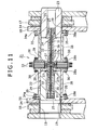
Figs. 11 and12 ,first brackets Fig. 10 ) to be connected to each other. On the other side,second brackets First pin holes 19 are provided in thefirst brackets second pin holes 20 are provided in thesecond brackets - It should be noted that the figure shows the case where a pair of
first brackets 16 on the inside and the outside and a pair ofsecond brackets 18 on the inside and the outside are provided with a small clearance inbetween. However, as a matter of convenience, thebrackets reference numerals Fig. 11 ) in the following description. - The
first brackets second brackets pin holes brackets pin connection device 21 provided between thebrackets - Hereinafter, the
brackets brackets - The
pin connection device 21 is provided with afirst pin 22 for connecting thefirst brackets second pin 23 for connecting thesecond brackets pins pin holes -
Fig. 11 respectively shows a pin insertion state on the right side and a pin removal state on the left side with respect to a center line. Hereinafter, a pin position on the right side ofFig. 11 is referred to as an insertion position and a pin position on the left side is referred to as a removal position, according to need. - Both the first and
second pins hydraulic cylinders 24. Both thehydraulic cylinders 24 have all the same configuration. Therefore, a description regarding to the cylinder configuration will basically be given only for one side hereinafter, and a separate description will be added for each of the cylinders according to need. - The
pins hydraulic cylinders 24. Thehydraulic cylinders 24 are formed by thepins pistons 25 and hollow piston rods (hereinafter, simply referred to as rods) 26 connected to thepistons 25 and extended and contracted by an oil supply and discharge effect from the exterior so that thepins - Both the
hydraulic cylinders 24 are formed as separately independent cylinders in which therods 26 are divided at a center part of the device. Both thecylinders 24 are arranged in series in a state that rod ends thereof opposing to each other support reaction force on the extending side for each other. - Specifically, in the rod ends of both the
cylinders 24, reactionforce transmitting portions 27 in a circular shape are provided projectingly to the outer peripheral side. Sinceabutment surfaces 27a serving as surfaces of both the reactionforce transmitting portions 27 opposing to each other are brought into abutment with each other in the rod axial direction. Therefore, the reaction force on the cylinder extending side is supported on the respective rod ends. - Meanwhile, on the outer peripheral sides of both the
pins pin guide members 28 are provided so that thepins - In the
pin guide members 28,outer collar portions 28a provided in outer ends thereof are fixed to and cantilevered by theinner brackets inner collar portions 28b) serving as free ends of thepin guide members 28, supportingplates 29 for receiving reaction force on the cylinder contracting side are attached. - The supporting
plate 29 is formed in a half-divided shape withring bodies pin guide members 28 on the both sides from the outside in the pin radial direction as shown inFig. 12 . - In a state that the inner peripheral side of the
plate 29 is convexly and concavely engaged with anengagement portion 27b provided in an outer peripheral part of an opposite surface to theabutment surface 27a in the reactionforce transmitting portion 27, an outer edge part of theabove plate 29 is detachably attached to theinner collar portion 28b of thepin guide member 28 bybolts 30. - Thereby, the reaction force on the cylinder contracting side at the time of pin removal is transmitted from the reaction
force transmitting portion 27 to the supportingplate 29 and supported in thepin guide member 28. - Meanwhile,
oil passages rod 26 in a tunnel shape extending in the rod axial direction. Both theoil passages pipe joint 33 provided between both thehydraulic cylinders 24 and an external pipe (not shown). - As mentioned above, supply and discharge of oil for the
hydraulic cylinders 24 are performed via the rods. - According to the
pin connection device 21, the entire length of the device is shortened. Therefore, even in the case where the boom width is narrow (a clearance between the brackets on the both sides is narrow), it is possible to assemble the device. - In the above prior art, the outer ends of the
pin guide members 28 are attached to and cantilevered by theinner brackets pin guide members 28 as follows. - A description will be given taking the
pin guide member 28 and theinner bracket 16 on the left side in the figure as an example. There is no problem when the outer end of thepin guide member 28 can directly be fixed to thebracket 16. However, since the clearance between the brackets is narrow, it is not possible to process screw holes or the like in thebracket 16. - Therefore, as shown in the figure, a
bushing 34 is press fitted to thepin hole 19 of thebracket 16, and aflange 34a is press fitted to an outer periphery of thebushing 34. Then, an outer periphery of theflange 34a is welded to thebracket 16, and theouter collar portion 28a of thepin guide member 28 is fixed to theflange 34a bybolts 35.
Patent Document:Japanese Patent No. 3399960 - However, according to the above prior art, first of all, there is a need for a work of fastening both the inner and outer ends of the
pin guide member 28 to the supportingplate 29 and the inner bracket 16 (theflange 34a of the bushing 34) by bolts. - In addition, there is a need for a process of press fitting the
flange 34a matching with a phase determined by a relationship with thepin guide member 28, a process of welding theflange 34a to thebracket 16, a process of performing difficult machine work on a surface of theinner bracket 16 prior to the above welding and the like. - Furthermore, the welding is a troublesome work of avoiding distortion in a pin hole diameter and a flange combining surface, and there is a need for cleaning up adhered spatter.
- Therefore, since the number of process is large, an assembling property is degraded and cost is increased. The device has a significant problem as a mass produced machine.
- Consequently, on the premise that a pair of pins are retained by pin guide members and perform a stroke operation so that connection portions of two members are connected to and disconnected from each other, the present invention is to provide a pin connection device capable of realizing improvement in the assembling property and cost reduction regarding to attachment of the pin guide members.
- In order to solve the above problem, the present invention adopts the following configuration.
- That is, the present invention is provided with first and second connection portions provided in two members to be connected to each other with a clearance therebetween, pin holes provided in both the connection portions, first and second pin guide members provided side by side in the axial direction between both the connection portions located on the inner side in a state that the first and second connection portions of the members are overlapped inside and outside, first and second pins adapted to perform a stroke operation in the opposite direction to each other in a state of being retained by both the first and second pin guide members and move between a connection position to be inserted into both the pin holes of both the first and second connection portions and a disconnection position to be removed from at least the pin holes of the connection portions on the outer side, a connection member provided detachably in the pin radial direction between inner ends of both the pin guide members opposing to each other, fastening means for detachably combining the inner ends of both the pin guide members to each other through the connection member, and supporting means for supporting outer ends of both the pin guide members in the pin radial direction with respect to the connection portions on the inner side.
- According to the present invention, the inner ends of both the pin guide members are combined and integrated with each other by the fastening means in a state that the connection member detachable in the pin radial direction is intervened between the inner ends. Therefore, regarding to assembly of the pin guide members, it is possible to omit a troublesome work of press fitting and welding the flange, the machine work on the flange combining surface prior to the above and the like, which are required in the prior art shown in
Figs. 11 and12 . - The outer ends of the pin guide members may only be supported in the pin radial direction. Therefore, it is possible to deal with a simplified structure such as a structure of supporting by the pins themselves (claim 2), and a structure of supporting by simple convexo-concave fitting (claim 3).
- Thereby, it is possible to reduce the number of process for the entire assembly of the pin guide members and simplify the work. Therefore, it is possible to realize the improvement in the assembling property and the cost reduction in a mass produced machine.
-
- [
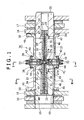
Fig. 1 ] A sectional view of a pin connection device according to a first embodiment of the present invention. - [
Fig. 2 ] A sectional view by line II-II ofFig. 1 . - [
Fig. 3 ] A sectional view by line III-III ofFig. 1 . - [
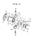
Fig. 4 ] A partially exploded perspective view of the above device. - [
Fig. 5 ] A sectional view of a pin connection device according to a second embodiment of the present invention. - [
Fig. 6 ] A sectional view by line VI-VI ofFig. 5 . - [
Fig. 7 ] A sectional view of a pin connection device according to a third embodiment of the present invention. - [
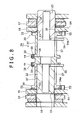
Fig. 8 ] A sectional view of a pin connection device according to a fourth embodiment of the present invention. - [
Fig. 9 ] A schematic side view of a cannibalizing machine to which the present invention is applied. - [
Fig. 10 ] A partial side view showing a connection state of boom sections at the time of assembling and disassembling the cannibalizing machine. - [
Fig. 11 ] A sectional view of a pin connection device according to a prior art of the present invention. - [
Fig. 12 ] A partially exploded perspective view of the above device. - Hereinafter, a description will be given to embodiments of the present invention with reference to
Figs. 1 to 8 . - A
pin connection device 36 according to a first embodiment is a hydraulic pin type. In the present embodiment, the same parts as the prior art shown inFigs. 11 and12 are given the same reference numerals, and a duplicated explanation thereof will be omitted. - As a basic configuration, the following points are the same as the prior art.
- (i)
First brackets Fig. 10 ) to be connected to each other. On the other side,second brackets first brackets second brackets - (ii) The
first brackets second brackets brackets - (iii) First and
second pins pin connection device 36 are integrated with cylinder tubes ofhydraulic cylinders 24. Thehydraulic cylinders 24 are formed by thepins pistons 25 andhollow rods 26 connected to thepistons 25. - (iv) Both the
hydraulic cylinders 24 are formed as separately independent cylinders in which therods 26 thereof are divided at a center part of the device. Reaction force on the cylinder extending side is supported on rod ends thereof opposing to each other throughabutment surfaces 27a of reactionforce transmitting portions 27. - (v)
Oil passages rods 26. Both theoil passages - On the outer peripheral sides of both the
pins pin guide members 37 are provided so that thepins - In the
pin guide members 37,inner collar portions 38 andouter collar portions 39 are respectively provided in inner ends and outer ends thereof projectingly to the outer periphery side. In a state that a supportingplate 40 serving as both a connection member and a member for receiving reaction force on the cylinder contracting side is intervened between theinner collar portions 38, theinner collar portions 38 are combined with each other bybolts 41 andnuts 42 serving as fastening means passing through the above three parts. - The supporting
plate 40 is formed in a half-divided shape in whichring bodies plates 29 on the both sides in the prior art shown inFigs. 11 and12 . In a state that the inner peripheral side of the supportingplate 40 is convexly and concavely engaged withengagement portions 27b of the reactionforce transmitting portions 27 so as to transmit the reaction force on the cylinder contracting side to thepin guide member 37, an outer edge part of theabove plate 40 is combined with theinner collar portions 38 of thepin guide members 37 as mentioned above. - Thereby, both the
pin guide members 37 are combined and integrated with each other through the supportingplate 40 in the inner ends thereof. - It should be noted that a
joint hole 43 passing through in the radial direction is provided inside the supportingplate 40. The pipe joints 33 are inserted and accommodated in thejoint hole 43. - In outer peripheral ends of both left and right surfaces of the supporting
plate 40,engagement edge portions 44 outwardly projecting are provided. Theengagement edge portions 44 are engaged with outer peripheries of theinner collar portions 38 of thepin guide members 37. Thereby, theabove plate 40 is positioned (centered) in the radial direction. - Further, pin
rotation preventing members 45 are attached to base ends of both thepins rotation preventing members 45 are engaged withrotation preventing grooves 46 provided in inner peripheral surfaces of both thepin guide members 37 extending in the axial direction. Thereby, rotation of both thepins - Next, a description will be given to a structure for supporting the outer ends of the
pin guide members 37 in the pin radial direction and fixing positions thereof (preventing rotation) in the circumferential direction. - Fitting
concave portions 47 are provided over the entire periphery on the inner periphery side of outer end surfaces of thepin guide members 37.
Meanwhile,bushings 48 with heads are press fitted and fixed to the pin holes 19 and 20 of theinner brackets concave portions 47 of thepin guide members 37 are fitted to the heads of thebushings 48 in the axial direction. - Thereby, the
pin guide members 37 are supported in the pin radial direction. That is, supporting means for supporting thepin guide member 37 in the radial direction is formed by thebushing 48 and the fittingconcave portions 47. - Both the first and
second pins outer brackets inner brackets pin guide member 37 is set so as to obtain the above state. - As mentioned above, both the
pins pin guide members 37 in the radial direction. - As shown in
Figs. 3 and4 , a projectingpiece 49 is provided in a part of an outer periphery of theouter collar portion 39. Meanwhile, in an inner surface of theinner bracket 16,rotation preventing protrusions 50 are provided so as to be engaged with the projectingpiece 49 in a state that the above projectingpiece 49 is sandwiched from the both sides in the circumferential direction. Thereby, a position of thepin guide member 37 is fixed in the circumferential direction. - It should be noted that at the time of assembling, after press fitting the bushing, both the
pin guide members 37 are inserted between theinner brackets plate 40. - As mentioned above, the inner ends of the both the
pin guide members 37 are combined by the bolts and integrated with each other in a state that the supportingplate 40 detachable in the pin radial direction is intervened between the inner ends. Therefore, regarding to assembly of thepin guide members 37, it is possible to omit a troublesome work of press fitting and welding a flange of the bushing, machine work on a flange combining surface prior to the above and the like, which are required in the prior art shown inFigs. 11 and12 . - The outer ends of the
pin guide members 37 may only be supported in the pin radial direction. Therefore, there is only a need for a simple operation of not press fitting but simple convexo-concave fitting to thebushing 48. - It should be noted that although the
rotation preventing protrusions 50 are welded to theinner brackets - Consequently, it is possible to reduce the number of process for the entire assembling work of the
pin guide members 37 and simplify the work. Therefore, it is possible to realize improvement in an assembling property and cost reduction in a mass produced machine. - Meanwhile, it is possible to fix the positions of the
pin guide members 37 in the circumferential direction with respect to theinner brackets pieces 49 and therotation preventing protrusions 50. Therefore, in the case of the hydraulic pin type as in the present embodiment, there is especially no fear that thepin guide members 37 are rotated so that an unreasonable load is imposed on a hydraulic piping system for thehydraulic cylinders 24 or the like. - Further, the supporting
plate 40 serving as both the connection member and a reaction force receiving member is formed in a half-divided shape with a pair of thering bodies plate 40. - A description will only be given to a difference from the first embodiment.
- In the first embodiment, both the
pin guide members 37 and the supportingplate 40 are combined with each other by the throughbolt 41. Meanwhile, in a second embodiment, both thepin guide members 37 are separately combined with the supportingplate 40 bybolts 51. - Even with the above configuration, the point that both the
pin guide members 37 are combined and integrated with each other through the supportingplate 40 is basically the same as the first embodiment. - As the supporting means for supporting the
pin guide member 37 in the pin radial direction, in the first embodiment, thebushings 48 are press fitted to the pin holes 19 and 20 of theinner brackets pin guide members 37 are fitted to thebushings 48. Meanwhile, in the second embodiment, instead of thebushings 48, fitting members (female members) 52 are welded and fixed to the inner surfaces of theinner brackets convex portions 53 provided in the outer ends of thepin guide members 37 are convexly and concavely fitted to the abovefitting members 52 in the axial direction. - According to the above configuration, it is possible to omit the
bushings 48 in the first embodiment and there is no need for the machine work on peripheral surfaces of the pin holes for press fitting the bushings. Therefore, the assembling property will be more improved. - Regarding to rotation preventing means, in the first embodiment, the projecting
piece 49 provided on thepin guide member 37 side is sandwiched by a pair of the rotating preventingprotrusions 50 provided on theinner bracket 16 side. Meanwhile, in the second embodiment on the contrary, a rotation preventingconcave portion 54a is provided in a projectingpiece 54 on thepin guide member 37 side, andaxial shape protrusions 55 projectingly provided on theinner brackets concave portion 54a. - It should be noted that the rotation preventing
concave portion 54a is formed in a long hole shape elongating in the radial direction so as to allow an accidental error in assembly. - As mentioned above, both the
pins outer brackets pin guide members 37 in the radial direction. - In a third embodiment, the outer ends of the
pin guide members 37 are only faced to the inner surfaces of theinner brackets - It should be noted that although the rotation preventing means is not shown here, the rotation preventing means of the first embodiment or the second embodiment may be adopted according to need.
- According to the above configuration, the number of parts and the number of process are further reduced so as to furthermore contribute to the improvement in the assembling property and the cost reduction.
- The first to third embodiments show the case of applying the present invention to the hydraulic pin type in which the
pins hydraulic cylinders 24. However, it is possible to apply the present invention to a manual pin type in which the operation is manually performed. - A fourth embodiment shows an application example to the manual pin type. In the present embodiment, the hydraulic cylinders are not used, and both the first and
second pins levers 56. - The
levers 56 are guided to the exterior by lever ports (slots) 57 provided in peripheral walls of both thepin guide members 37 extending in the pin longitudinal direction. - In the present embodiment, both the
pin guide members 37 are combined and integrated with each other bynon-through type bolts 59 through aconnection member 58 in a thick plate shape intervened between theinner collar portions 38. - The
connection member 58 is formed in a half divided shape as in the other embodiments (the half-divided state is not shown), and provided with theengagement edge portions 44 outwardly projecting in outer peripheral ends of both left and right side surfaces. The aboveengagement edge portions 44 are engaged with the outer peripheries of theinner collar portions 38 of thepin guide members 37 so as to position (center) in the radial direction. - Meanwhile, the present embodiment exemplifies the case of applying the supporting means for supporting the outer ends of both the
pin guide members 37 in the pin radial direction and the rotation preventing means which are the same as the second embodiment (the same parts asFig. 5 are given the same reference numerals, and a explanation thereof will be omitted). However, both the means may also be the same as the first embodiment. - Other Embodiment
- (1) The supporting
plate 40 of the first to third embodiments and theconnection member 58 of the fourth embodiment may be formed not in a half-divided shape but in one ring shape, when there is no problem in assembly. - (2) In the case where the outer ends of the
pin guide members 37 are supported by the convex and concave fitting parts in the radial direction to theinner brackets pins inner brackets - (3) The present invention is not limited to a connection part between boom sections, but can be applied to an attachment part of a
compression crushing device 12 to a front end of a boom in a cannibalizing machine shown inFig. 9 (in the case where a bucket is attached instead of thecompression crushing device 12, an attachment part of the bucket), attachment parts ofboom cylinders 8 to 11, and an attachment part of a boom foot of afirst boom 4. The present invention can be applied not only to the cannibalizing machine but also to attachment parts of an attachment and connection parts between members in various working machines such as a crane and an excavator. Industrial Applicability - The present invention exhibits a useful effect of reducing the number of process in assembling a pin guide member so as to simplify a work.
Claims (11)
- A pin connection device, comprising first and second connection portions provided in two members to be connected to each other with a clearance therebetween; pin holes provided in both said connection portions; first and second pin guide members provided side by side in the axial direction between both said connection portions located on the inner side in a state that said first and second connection portions of the members are overlapped inside and outside; first and second pins adapted to perform a stroke operation in the opposite direction to each other in a state of being retained by both said first and second pin guide members and move between a connection position to be inserted into both said pin holes of both said first and second connection portions and a disconnection position to be removed from at least said pin holes of said connection portions on the outer side; a connection member provided detachably in the pin radial direction between inner ends of both said pin guide members opposing to each other; fastening means for detachably combining the inner ends of both said pin guide members to each other through said connection member; and supporting means for supporting outer ends of both said pin guide members in the pin radial direction with respect to said connection portions on the inner side.
- The pin connection device according to claim 1, wherein said supporting means is formed by said pin holes of said connection portions on the inner side and both said first and second pins inserted and retained into said pin holes at the disconnection position.
- The pin connection device according to claim 1, wherein said supporting means is formed by convex portions provided in one of both said connection portions on the inner side and the outer ends of both said pin guide members; and concave portions provided in the other so as to be fitted to the convex portions in the pin axial direction and support both said pin guide members in the radial direction.
- The pin connection device according to any of claims 1 to 3, further comprising rotation preventing means for fixing positions of both said pin guide members in the circumferential direction with respect to said connection-portions on the inner side.
- The pin connection device according to claim 4, wherein said rotation preventing means is formed by a projecting piece provided in one of both said pin guide members and said connection portions on the inner side and a rotation preventing member provided in the other so as to be engaged with the projecting piece in a state that a position of the projecting piece is fixed in the circumferential direction.
- The pin connection device according to any of claims 1 to 5, wherein said connection member is formed in a half-divided shape including a pair of ring bodies in a semicircular shape detachable in the pin radial direction, and both the ring bodies of said connection member are attached to both said pin guide members by said fastening means.
- The pin connection device according to any of claims 1 to 6, wherein lever ports extending in the pin longitudinal direction are provided in peripheral walls of both said pin guide members, and levers for manually operating both said pins between the connection position and the disconnection position are guided from the lever ports to the exterior.
- The pin connection device according to any of claims 1 to 6, further comprising first and second hydraulic cylinders adapted to drive both said first and second pins separately, both the hydraulic cylinders being provided side by side in the coaxial direction between said connection portions on the inner side, and in a state that reaction force on the cylinder extending side is transmitted to each other by ends opposing to each other, while reaction force on the cylinder contracting side is transmitted to both said pin guide members through said connection member.
- The pin connection device according to claim 8, wherein said first and second hydraulic cylinders are arranged in a state that piston rods thereof are opposed to each other, and ends of the piston rods are combined with an inner peripheral part of said connection member in a ring shape in a state that the reaction force on the cylinder contracting side is transmittable to said connection member.
- The pin connection device according to claim 8 or 9, wherein cylinder tubes of both said first and second hydraulic cylinders are respectively integrated with said pins.
- The pin connection device according to claim 9 or 10, wherein oil passages on the extending side and the contracting side passing through to oil chambers on the extending side and the contracting side of said cylinders are provided in the piston rods of both said hydraulic cylinders, and a pipe joint adapted to join the oil passages with external hydraulic pipes is accommodated in said connection member.
Applications Claiming Priority (2)
| Application Number | Priority Date | Filing Date | Title |
|---|---|---|---|
| JP2006024609A JP4867371B2 (en) | 2006-02-01 | 2006-02-01 | Pin coupling device |
| PCT/JP2006/324575 WO2007088674A1 (en) | 2006-02-01 | 2006-12-08 | Pin connection device |
Publications (3)
| Publication Number | Publication Date |
|---|---|
| EP1980672A1 true EP1980672A1 (en) | 2008-10-15 |
| EP1980672A4 EP1980672A4 (en) | 2010-06-02 |
| EP1980672B1 EP1980672B1 (en) | 2013-05-01 |
Family
ID=38327258
Family Applications (1)
| Application Number | Title | Priority Date | Filing Date |
|---|---|---|---|
| EP06834330.0A Not-in-force EP1980672B1 (en) | 2006-02-01 | 2006-12-08 | Pin connection device |
Country Status (5)
| Country | Link |
|---|---|
| US (1) | US7963716B2 (en) |
| EP (1) | EP1980672B1 (en) |
| JP (1) | JP4867371B2 (en) |
| CN (1) | CN101336346B (en) |
| WO (1) | WO2007088674A1 (en) |
Cited By (3)
| Publication number | Priority date | Publication date | Assignee | Title |
|---|---|---|---|---|
| EP3244079A1 (en) * | 2016-05-11 | 2017-11-15 | BAUER Maschinen GmbH | Bolted assembly and swing arm with bolted assembly for construction machine |
| US10119283B2 (en) | 2012-08-31 | 2018-11-06 | Putzmeister Engineering Gmbh | Concrete distributor mast |
| WO2022042838A1 (en) * | 2020-08-26 | 2022-03-03 | Sandvik Mining And Construction Oy | A pin mounting arrangement and a mining vehicle |
Families Citing this family (19)
| Publication number | Priority date | Publication date | Assignee | Title |
|---|---|---|---|---|
| FI20080652A0 (en) * | 2008-12-11 | 2008-12-11 | Yrjoe Raunisto | Quick Coupling Arrangements |
| JP4806049B2 (en) * | 2009-03-27 | 2011-11-02 | 日立建機株式会社 | Two-member connecting device |
| JP5154502B2 (en) * | 2009-04-27 | 2013-02-27 | 住友建機株式会社 | Attachment disassembly device for aerial dismantling machine |
| JP2013067967A (en) * | 2011-09-21 | 2013-04-18 | Kobelco Contstruction Machinery Ltd | Work attachment and work machine with the same |
| US9815674B2 (en) | 2013-02-21 | 2017-11-14 | Manitowoc Crane Companies, Llc | Pin puller for crane connections |
| EP2781660B1 (en) | 2013-03-21 | 2018-04-18 | Caterpillar Global Mining LLC | Hydraulic actuator |
| US9308123B2 (en) | 2013-09-16 | 2016-04-12 | Neuraxis, Llc | Methods and devices for applying localized thermal therapy |
| US8911486B1 (en) | 2013-09-16 | 2014-12-16 | Neuraxis, Llc | Implantable devices for thermal therapy and related methods |
| RU2553622C2 (en) * | 2013-11-13 | 2015-06-20 | Федеральное государственное бюджетное образовательное учреждение высшего профессионального образования "Сибирский государственный индустриальный университет" | Dust and water-proof hinge |
| JP6592327B2 (en) * | 2015-10-28 | 2019-10-16 | キャタピラー エス エー アール エル | Work machine swivel joint |
| JP6447581B2 (en) * | 2016-06-17 | 2019-01-09 | コベルコ建機株式会社 | Connecting pin pulling jig and crane |
| JP7030504B2 (en) * | 2017-12-22 | 2022-03-07 | 株式会社クボタ | Working machine |
| CN110498261B (en) * | 2018-12-12 | 2024-07-26 | 广东天酿智能装备有限公司 | Handling equipment and handling method |
| DE102020110406A1 (en) * | 2020-04-16 | 2021-10-21 | Liebherr-Werk Ehingen Gmbh | Mobile stud pulling device |
| US11952738B2 (en) | 2020-09-18 | 2024-04-09 | Great Plains Manufacturing, Inc. | Attachment coupler |
| DE102020131617B4 (en) * | 2020-11-30 | 2022-06-23 | Liebherr-Werk Ehingen Gmbh | Mobile crane comprising an upper carriage with at least one bearing point for bolting on a boom |
| US12449000B2 (en) | 2021-11-19 | 2025-10-21 | Caterpillar Inc. | Compact actuated shear pin |
| US12325972B2 (en) | 2022-04-04 | 2025-06-10 | Caterpillar Inc. | Control system for actuated pins |
| DE102022125112A1 (en) | 2022-09-29 | 2024-04-04 | OilQuick Deutschland KG | Quick coupler |
Family Cites Families (21)
| Publication number | Priority date | Publication date | Assignee | Title |
|---|---|---|---|---|
| CA1128714A (en) * | 1978-11-30 | 1982-08-03 | Yoshiju Ichise | Windscreen wiper blade |
| DE4010224C2 (en) * | 1990-03-30 | 1994-05-19 | Porsche Ag | Quick change device |
| US5010962A (en) * | 1990-04-30 | 1991-04-30 | Caterpillar Inc. | Indicating apparatus for a coupling |
| US5282566A (en) * | 1992-12-14 | 1994-02-01 | Caterpillar Inc. | Lift arm assembly process |
| FR2705936B1 (en) * | 1993-06-04 | 1995-08-04 | Valeo Systemes Dessuyage | Wiper device comprising an articulation between a crank and a connecting rod. |
| FI944214A0 (en) * | 1994-02-09 | 1994-09-13 | Airi Raunisto | Snabbkopplingsanordning |
| DE19651507A1 (en) | 1995-12-30 | 1997-07-03 | Samsung Heavy Ind | Device for detachably attaching an accessory to a heavy device |
| KR100202087B1 (en) * | 1995-12-30 | 1999-06-15 | 토니헬샴 | Attachment detachment device of heavy equipment |
| SE9701887D0 (en) * | 1997-05-21 | 1997-05-21 | Accima Ab | Device for detachable connection of a working tool and an excavator's control arm |
| JP3056706B2 (en) * | 1997-10-07 | 2000-06-26 | 新キャタピラー三菱株式会社 | Attachment attachment / detachment device for work machines |
| KR200271162Y1 (en) * | 1999-05-11 | 2002-04-10 | 이원해 | coupler for excavator |
| AU773725B2 (en) * | 1999-05-15 | 2004-06-03 | A Ward Attachments Limited | Connection apparatus |
| DE29909329U1 (en) * | 1999-05-28 | 1999-08-12 | Liebherr-Hydraulikbagger GmbH, 88457 Kirchdorf | Quick coupling for excavator tools |
| US6499904B2 (en) * | 2001-01-19 | 2002-12-31 | Nye Manufacturing Ltd. | Excavator coupler using fluid operated actuator |
| KR100430064B1 (en) * | 2001-05-18 | 2004-05-03 | 한국기계연구원 | Quick Coupler Use Of Excavator |
| CN1258029C (en) * | 2001-09-26 | 2006-05-31 | 汉宇Tnc公司 | Attachment couplings for heavy machinery |
| KR100993158B1 (en) * | 2001-09-26 | 2010-11-09 | 가부시키가이샤 고마쓰 세이사쿠쇼 | Work tool connector |
| US6662681B2 (en) * | 2002-01-14 | 2003-12-16 | Kent Demolition, Inc. | Connector assembly for mounting an implement to a prime mover |
| JP3925530B2 (en) * | 2003-10-24 | 2007-06-06 | コベルコ建機株式会社 | Work machine and boom assembly / disassembly method thereof |
| JP4100512B2 (en) * | 2003-10-31 | 2008-06-11 | 日立建機株式会社 | Detachment device with working machine pins |
| US7690880B2 (en) * | 2006-04-25 | 2010-04-06 | Clark Equipment Company | Locking device for hydraulic attachment interface |
-
2006
- 2006-02-01 JP JP2006024609A patent/JP4867371B2/en not_active Expired - Fee Related
- 2006-12-08 EP EP06834330.0A patent/EP1980672B1/en not_active Not-in-force
- 2006-12-08 WO PCT/JP2006/324575 patent/WO2007088674A1/en not_active Ceased
- 2006-12-08 US US12/161,764 patent/US7963716B2/en active Active
- 2006-12-08 CN CN2006800521731A patent/CN101336346B/en not_active Expired - Fee Related
Cited By (4)
| Publication number | Priority date | Publication date | Assignee | Title |
|---|---|---|---|---|
| US10119283B2 (en) | 2012-08-31 | 2018-11-06 | Putzmeister Engineering Gmbh | Concrete distributor mast |
| EP3244079A1 (en) * | 2016-05-11 | 2017-11-15 | BAUER Maschinen GmbH | Bolted assembly and swing arm with bolted assembly for construction machine |
| US10267014B2 (en) | 2016-05-11 | 2019-04-23 | Bauer Maschinen Gmbh | Bolt connection and swivel lever with bolt connection for construction machine |
| WO2022042838A1 (en) * | 2020-08-26 | 2022-03-03 | Sandvik Mining And Construction Oy | A pin mounting arrangement and a mining vehicle |
Also Published As
| Publication number | Publication date |
|---|---|
| CN101336346A (en) | 2008-12-31 |
| US20100226710A1 (en) | 2010-09-09 |
| JP4867371B2 (en) | 2012-02-01 |
| US7963716B2 (en) | 2011-06-21 |
| EP1980672B1 (en) | 2013-05-01 |
| WO2007088674A1 (en) | 2007-08-09 |
| CN101336346B (en) | 2010-11-17 |
| JP2007205451A (en) | 2007-08-16 |
| EP1980672A4 (en) | 2010-06-02 |
Similar Documents
| Publication | Publication Date | Title |
|---|---|---|
| EP1980672B1 (en) | Pin connection device | |
| CN100410491C (en) | Pipe blade assembling machine for rectangular shield | |
| US20120067840A1 (en) | Pinned connection system for crane column segments | |
| CA2832478A1 (en) | A tubing reel assembly for coiled tubing systems | |
| JP2010089776A (en) | Trunnion transportation system and crane using same | |
| AU2021101828A4 (en) | Hydraulic rotary quick coupling device for oil circuit and control method thereof | |
| CN112854328B (en) | Hydraulic drive's excavator accessory quick connector and excavator | |
| JP2013108247A (en) | Apparatus for connecting/disconnecting upper and lower connecting pins of work machine and method for assembling/disassembling the work machine | |
| JP4277765B2 (en) | Pin coupling device, pin coupling device assembling method and work machine | |
| CN109577405B (en) | Hydraulic quick-change mechanism for accessory | |
| JP4877084B2 (en) | Hydraulic cylinder connection structure and construction machine having the same | |
| JP2004076325A (en) | Work machine desorption device | |
| JP4693756B2 (en) | Joint attachment / detachment device | |
| JP2009013730A (en) | Connection pin attaching/detaching jig | |
| CA2078393C (en) | Multi-coupling device for crane hydraulic lines | |
| CN214833000U (en) | A trencher excavator wheel | |
| JP2006057837A (en) | Pin coupling device and work machine with pin coupling device | |
| KR102426373B1 (en) | Altitude-limited gound improvement equipment | |
| CN218907437U (en) | High-strength caterpillar link | |
| CN103061680B (en) | Sliding frame, power device and rotary drilling rig | |
| KR20090069376A (en) | Detachable device for heavy equipment counter weight | |
| CN114319357B (en) | Static pile pressing machine | |
| RU2845406C1 (en) | Bracket for lifting rotary platform of excavator | |
| KR102746558B1 (en) | Excavator in which the decomposition assembly facilitates | |
| CN224243992U (en) | Connecting structure for A-shaped frame, A-shaped frame and working machine |
Legal Events
| Date | Code | Title | Description |
|---|---|---|---|
| PUAI | Public reference made under article 153(3) epc to a published international application that has entered the european phase |
Free format text: ORIGINAL CODE: 0009012 |
|
| 17P | Request for examination filed |
Effective date: 20080717 |
|
| AK | Designated contracting states |
Kind code of ref document: A1 Designated state(s): AT BE BG CH CY CZ DE DK EE ES FI FR GB GR HU IE IS IT LI LT LU LV MC NL PL PT RO SE SI SK TR |
|
| RIC1 | Information provided on ipc code assigned before grant |
Ipc: F16C 11/04 20060101ALI20081128BHEP Ipc: E02F 3/38 20060101ALI20081128BHEP Ipc: F16B 9/00 20060101AFI20081128BHEP Ipc: E02F 9/00 20060101ALI20081128BHEP |
|
| A4 | Supplementary search report drawn up and despatched |
Effective date: 20100504 |
|
| 17Q | First examination report despatched |
Effective date: 20110519 |
|
| DAX | Request for extension of the european patent (deleted) | ||
| GRAP | Despatch of communication of intention to grant a patent |
Free format text: ORIGINAL CODE: EPIDOSNIGR1 |
|
| GRAS | Grant fee paid |
Free format text: ORIGINAL CODE: EPIDOSNIGR3 |
|
| GRAA | (expected) grant |
Free format text: ORIGINAL CODE: 0009210 |
|
| AK | Designated contracting states |
Kind code of ref document: B1 Designated state(s): AT BE BG CH CY CZ DE DK EE ES FI FR GB GR HU IE IS IT LI LT LU LV MC NL PL PT RO SE SI SK TR |
|
| REG | Reference to a national code |
Ref country code: GB Ref legal event code: FG4D |
|
| REG | Reference to a national code |
Ref country code: AT Ref legal event code: REF Ref document number: 610124 Country of ref document: AT Kind code of ref document: T Effective date: 20130515 Ref country code: CH Ref legal event code: EP |
|
| REG | Reference to a national code |
Ref country code: IE Ref legal event code: FG4D |
|
| REG | Reference to a national code |
Ref country code: DE Ref legal event code: R096 Ref document number: 602006036107 Country of ref document: DE Effective date: 20130627 |
|
| REG | Reference to a national code |
Ref country code: AT Ref legal event code: MK05 Ref document number: 610124 Country of ref document: AT Kind code of ref document: T Effective date: 20130501 |
|
| REG | Reference to a national code |
Ref country code: NL Ref legal event code: VDEP Effective date: 20130501 |
|
| REG | Reference to a national code |
Ref country code: LT Ref legal event code: MG4D |
|
| PG25 | Lapsed in a contracting state [announced via postgrant information from national office to epo] |
Ref country code: FI Free format text: LAPSE BECAUSE OF FAILURE TO SUBMIT A TRANSLATION OF THE DESCRIPTION OR TO PAY THE FEE WITHIN THE PRESCRIBED TIME-LIMIT Effective date: 20130501 Ref country code: SE Free format text: LAPSE BECAUSE OF FAILURE TO SUBMIT A TRANSLATION OF THE DESCRIPTION OR TO PAY THE FEE WITHIN THE PRESCRIBED TIME-LIMIT Effective date: 20130501 Ref country code: SI Free format text: LAPSE BECAUSE OF FAILURE TO SUBMIT A TRANSLATION OF THE DESCRIPTION OR TO PAY THE FEE WITHIN THE PRESCRIBED TIME-LIMIT Effective date: 20130501 Ref country code: GR Free format text: LAPSE BECAUSE OF FAILURE TO SUBMIT A TRANSLATION OF THE DESCRIPTION OR TO PAY THE FEE WITHIN THE PRESCRIBED TIME-LIMIT Effective date: 20130802 Ref country code: IS Free format text: LAPSE BECAUSE OF FAILURE TO SUBMIT A TRANSLATION OF THE DESCRIPTION OR TO PAY THE FEE WITHIN THE PRESCRIBED TIME-LIMIT Effective date: 20130901 Ref country code: AT Free format text: LAPSE BECAUSE OF FAILURE TO SUBMIT A TRANSLATION OF THE DESCRIPTION OR TO PAY THE FEE WITHIN THE PRESCRIBED TIME-LIMIT Effective date: 20130501 Ref country code: LT Free format text: LAPSE BECAUSE OF FAILURE TO SUBMIT A TRANSLATION OF THE DESCRIPTION OR TO PAY THE FEE WITHIN THE PRESCRIBED TIME-LIMIT Effective date: 20130501 Ref country code: PT Free format text: LAPSE BECAUSE OF FAILURE TO SUBMIT A TRANSLATION OF THE DESCRIPTION OR TO PAY THE FEE WITHIN THE PRESCRIBED TIME-LIMIT Effective date: 20130902 Ref country code: ES Free format text: LAPSE BECAUSE OF FAILURE TO SUBMIT A TRANSLATION OF THE DESCRIPTION OR TO PAY THE FEE WITHIN THE PRESCRIBED TIME-LIMIT Effective date: 20130812 |
|
| PG25 | Lapsed in a contracting state [announced via postgrant information from national office to epo] |
Ref country code: CY Free format text: LAPSE BECAUSE OF FAILURE TO SUBMIT A TRANSLATION OF THE DESCRIPTION OR TO PAY THE FEE WITHIN THE PRESCRIBED TIME-LIMIT Effective date: 20130501 Ref country code: PL Free format text: LAPSE BECAUSE OF FAILURE TO SUBMIT A TRANSLATION OF THE DESCRIPTION OR TO PAY THE FEE WITHIN THE PRESCRIBED TIME-LIMIT Effective date: 20130501 Ref country code: BG Free format text: LAPSE BECAUSE OF FAILURE TO SUBMIT A TRANSLATION OF THE DESCRIPTION OR TO PAY THE FEE WITHIN THE PRESCRIBED TIME-LIMIT Effective date: 20130801 |
|
| PG25 | Lapsed in a contracting state [announced via postgrant information from national office to epo] |
Ref country code: LV Free format text: LAPSE BECAUSE OF FAILURE TO SUBMIT A TRANSLATION OF THE DESCRIPTION OR TO PAY THE FEE WITHIN THE PRESCRIBED TIME-LIMIT Effective date: 20130501 |
|
| PG25 | Lapsed in a contracting state [announced via postgrant information from national office to epo] |
Ref country code: DK Free format text: LAPSE BECAUSE OF FAILURE TO SUBMIT A TRANSLATION OF THE DESCRIPTION OR TO PAY THE FEE WITHIN THE PRESCRIBED TIME-LIMIT Effective date: 20130501 Ref country code: BE Free format text: LAPSE BECAUSE OF FAILURE TO SUBMIT A TRANSLATION OF THE DESCRIPTION OR TO PAY THE FEE WITHIN THE PRESCRIBED TIME-LIMIT Effective date: 20130501 Ref country code: CZ Free format text: LAPSE BECAUSE OF FAILURE TO SUBMIT A TRANSLATION OF THE DESCRIPTION OR TO PAY THE FEE WITHIN THE PRESCRIBED TIME-LIMIT Effective date: 20130501 Ref country code: SK Free format text: LAPSE BECAUSE OF FAILURE TO SUBMIT A TRANSLATION OF THE DESCRIPTION OR TO PAY THE FEE WITHIN THE PRESCRIBED TIME-LIMIT Effective date: 20130501 Ref country code: EE Free format text: LAPSE BECAUSE OF FAILURE TO SUBMIT A TRANSLATION OF THE DESCRIPTION OR TO PAY THE FEE WITHIN THE PRESCRIBED TIME-LIMIT Effective date: 20130501 |
|
| PG25 | Lapsed in a contracting state [announced via postgrant information from national office to epo] |
Ref country code: NL Free format text: LAPSE BECAUSE OF FAILURE TO SUBMIT A TRANSLATION OF THE DESCRIPTION OR TO PAY THE FEE WITHIN THE PRESCRIBED TIME-LIMIT Effective date: 20130501 Ref country code: RO Free format text: LAPSE BECAUSE OF FAILURE TO SUBMIT A TRANSLATION OF THE DESCRIPTION OR TO PAY THE FEE WITHIN THE PRESCRIBED TIME-LIMIT Effective date: 20130501 |
|
| PLBE | No opposition filed within time limit |
Free format text: ORIGINAL CODE: 0009261 |
|
| STAA | Information on the status of an ep patent application or granted ep patent |
Free format text: STATUS: NO OPPOSITION FILED WITHIN TIME LIMIT |
|
| 26N | No opposition filed |
Effective date: 20140204 |
|
| REG | Reference to a national code |
Ref country code: DE Ref legal event code: R097 Ref document number: 602006036107 Country of ref document: DE Effective date: 20140204 |
|
| REG | Reference to a national code |
Ref country code: CH Ref legal event code: PL |
|
| PG25 | Lapsed in a contracting state [announced via postgrant information from national office to epo] |
Ref country code: LU Free format text: LAPSE BECAUSE OF FAILURE TO SUBMIT A TRANSLATION OF THE DESCRIPTION OR TO PAY THE FEE WITHIN THE PRESCRIBED TIME-LIMIT Effective date: 20131208 Ref country code: MC Free format text: LAPSE BECAUSE OF FAILURE TO SUBMIT A TRANSLATION OF THE DESCRIPTION OR TO PAY THE FEE WITHIN THE PRESCRIBED TIME-LIMIT Effective date: 20130501 |
|
| REG | Reference to a national code |
Ref country code: IE Ref legal event code: MM4A |
|
| PG25 | Lapsed in a contracting state [announced via postgrant information from national office to epo] |
Ref country code: LI Free format text: LAPSE BECAUSE OF NON-PAYMENT OF DUE FEES Effective date: 20131231 Ref country code: CH Free format text: LAPSE BECAUSE OF NON-PAYMENT OF DUE FEES Effective date: 20131231 Ref country code: IE Free format text: LAPSE BECAUSE OF NON-PAYMENT OF DUE FEES Effective date: 20131208 |
|
| PG25 | Lapsed in a contracting state [announced via postgrant information from national office to epo] |
Ref country code: TR Free format text: LAPSE BECAUSE OF FAILURE TO SUBMIT A TRANSLATION OF THE DESCRIPTION OR TO PAY THE FEE WITHIN THE PRESCRIBED TIME-LIMIT Effective date: 20130501 |
|
| PG25 | Lapsed in a contracting state [announced via postgrant information from national office to epo] |
Ref country code: HU Free format text: LAPSE BECAUSE OF FAILURE TO SUBMIT A TRANSLATION OF THE DESCRIPTION OR TO PAY THE FEE WITHIN THE PRESCRIBED TIME-LIMIT; INVALID AB INITIO Effective date: 20061208 |
|
| REG | Reference to a national code |
Ref country code: FR Ref legal event code: PLFP Year of fee payment: 10 |
|
| REG | Reference to a national code |
Ref country code: FR Ref legal event code: PLFP Year of fee payment: 11 |
|
| REG | Reference to a national code |
Ref country code: FR Ref legal event code: PLFP Year of fee payment: 12 |
|
| PGFP | Annual fee paid to national office [announced via postgrant information from national office to epo] |
Ref country code: IT Payment date: 20221111 Year of fee payment: 17 Ref country code: GB Payment date: 20221027 Year of fee payment: 17 Ref country code: FR Payment date: 20221110 Year of fee payment: 17 Ref country code: DE Payment date: 20220622 Year of fee payment: 17 |
|
| REG | Reference to a national code |
Ref country code: DE Ref legal event code: R119 Ref document number: 602006036107 Country of ref document: DE |
|
| GBPC | Gb: european patent ceased through non-payment of renewal fee |
Effective date: 20231208 |
|
| PG25 | Lapsed in a contracting state [announced via postgrant information from national office to epo] |
Ref country code: DE Free format text: LAPSE BECAUSE OF NON-PAYMENT OF DUE FEES Effective date: 20240702 |
|
| PG25 | Lapsed in a contracting state [announced via postgrant information from national office to epo] |
Ref country code: GB Free format text: LAPSE BECAUSE OF NON-PAYMENT OF DUE FEES Effective date: 20231208 |
|
| PG25 | Lapsed in a contracting state [announced via postgrant information from national office to epo] |
Ref country code: FR Free format text: LAPSE BECAUSE OF NON-PAYMENT OF DUE FEES Effective date: 20231231 |
|
| PG25 | Lapsed in a contracting state [announced via postgrant information from national office to epo] |
Ref country code: GB Free format text: LAPSE BECAUSE OF NON-PAYMENT OF DUE FEES Effective date: 20231208 Ref country code: FR Free format text: LAPSE BECAUSE OF NON-PAYMENT OF DUE FEES Effective date: 20231231 Ref country code: DE Free format text: LAPSE BECAUSE OF NON-PAYMENT OF DUE FEES Effective date: 20240702 |
|
| PG25 | Lapsed in a contracting state [announced via postgrant information from national office to epo] |
Ref country code: IT Free format text: LAPSE BECAUSE OF NON-PAYMENT OF DUE FEES Effective date: 20231208 |